US4543572A - Road map display system with indications of a vehicle position and destination - Google Patents
Road map display system with indications of a vehicle position and destinationDownload PDFInfo
- Publication number
- US4543572A US4543572AUS06/373,168US37316882AUS4543572AUS 4543572 AUS4543572 AUS 4543572AUS 37316882 AUS37316882 AUS 37316882AUS 4543572 AUS4543572 AUS 4543572A
- Authority
- US
- United States
- Prior art keywords
- map
- display
- memory
- image data
- vehicle
- Prior art date
- Legal status (The legal status is an assumption and is not a legal conclusion. Google has not performed a legal analysis and makes no representation as to the accuracy of the status listed.)
- Expired - Lifetime
Links
Images


Classifications
- G—PHYSICS
- G01—MEASURING; TESTING
- G01C—MEASURING DISTANCES, LEVELS OR BEARINGS; SURVEYING; NAVIGATION; GYROSCOPIC INSTRUMENTS; PHOTOGRAMMETRY OR VIDEOGRAMMETRY
- G01C21/00—Navigation; Navigational instruments not provided for in groups G01C1/00 - G01C19/00
- G01C21/26—Navigation; Navigational instruments not provided for in groups G01C1/00 - G01C19/00 specially adapted for navigation in a road network
- G01C21/34—Route searching; Route guidance
- G01C21/36—Input/output arrangements for on-board computers
- G01C21/3667—Display of a road map
- G01C21/367—Details, e.g. road map scale, orientation, zooming, illumination, level of detail, scrolling of road map or positioning of current position marker
- G—PHYSICS
- G01—MEASURING; TESTING
- G01C—MEASURING DISTANCES, LEVELS OR BEARINGS; SURVEYING; NAVIGATION; GYROSCOPIC INSTRUMENTS; PHOTOGRAMMETRY OR VIDEOGRAMMETRY
- G01C21/00—Navigation; Navigational instruments not provided for in groups G01C1/00 - G01C19/00
- G01C21/20—Instruments for performing navigational calculations
- G01C21/22—Plotting boards
- G—PHYSICS
- G01—MEASURING; TESTING
- G01C—MEASURING DISTANCES, LEVELS OR BEARINGS; SURVEYING; NAVIGATION; GYROSCOPIC INSTRUMENTS; PHOTOGRAMMETRY OR VIDEOGRAMMETRY
- G01C21/00—Navigation; Navigational instruments not provided for in groups G01C1/00 - G01C19/00
- G01C21/26—Navigation; Navigational instruments not provided for in groups G01C1/00 - G01C19/00 specially adapted for navigation in a road network
- G01C21/34—Route searching; Route guidance
- G01C21/36—Input/output arrangements for on-board computers
- G01C21/3667—Display of a road map
- G01C21/3673—Labelling using text of road map data items, e.g. road names, POI names
- G—PHYSICS
- G06—COMPUTING OR CALCULATING; COUNTING
- G06T—IMAGE DATA PROCESSING OR GENERATION, IN GENERAL
- G06T15/00—3D [Three Dimensional] image rendering
- G—PHYSICS
- G09—EDUCATION; CRYPTOGRAPHY; DISPLAY; ADVERTISING; SEALS
- G09B—EDUCATIONAL OR DEMONSTRATION APPLIANCES; APPLIANCES FOR TEACHING, OR COMMUNICATING WITH, THE BLIND, DEAF OR MUTE; MODELS; PLANETARIA; GLOBES; MAPS; DIAGRAMS
- G09B29/00—Maps; Plans; Charts; Diagrams, e.g. route diagram
- G09B29/10—Map spot or coordinate position indicators; Map reading aids
- G09B29/106—Map spot or coordinate position indicators; Map reading aids using electronic means
Definitions
- the present inventionrelates generally to a road map display system for displaying a road map and symbols representing the positions of a vehicle and a designated destination on a screen. More particularly, the invention relates to a road map display system which displays the relationship between the vehicle position and destination and updates the display according to the movement of the vehicle.
- a display system for displaying the road map and the vehicle position on the display roadcan help the vehicle driver find his way.
- a pilot system for a shipis disclosed in the first publication of the Japanese Patent Application Sho 52-159895 (Tokkai Sho 54-89767, published July 17, 1979).
- a method for displaying a sea chart with an indication of the ship positionThe sea chart is moved on the display according to the travelling distance and travelling direction of the ship.
- coordinates of the displayed sea chartare modified with respect to the position and travelling direction of the ship.
- the sea chartis stored in a digital memory as plotted coordinates.
- a microcomputeris used for processing modifications of the sea chart coordinates and for calculation of the ship position based on a sensor, which measures travelling distance and detects the direction of the ship.
- Tokkai Sho 52-141662published on Nov. 26, 1977, shows a map display system for an automotive vehicle.
- microfilmis used to store the map.
- the indication of the vehicle positionwill move in accordance with the travelling distance and travelling direction of the vehicle.
- Another and more specific object of the present inventionis to provide a road map display system having a display coordinate system centered between the vehicle position and the destination so that the relationship between the vehicle position and the destination can be readily understood.
- a road map display systemwhich comprises a map memory for storing map data, a sensor for detecting the travelling distance and travelling direction of a vehicle and outputting a signal representative of the rotation angle through which the map is rotated, an arithmetic means for calculating the coordinates of a point intermediate between the vehicle position and the destination, a coordinate transforming means which transforms the map data and the display coordinates of a mark representing the destination in accordance with the rotation angle so that the intermediate point coincides with a predetermined position on a display screen and a mark representing the present position and orientation of the vehicle facing a predetermined direction, a display memory in which the map image in the transformed coordinate system, the vehicle mark, and the destination mark are stored, and a display means for displaying the information stored in the display memory on the display screen.
- the road map display systemdisplays a road map stored in a map memory with symbols representing the positions of the vehicle and its destination.
- the vehicle markalways points upward along the y-axis of the screen to show the travelling direction.
- the display coordinate systemis transformed from time to time according to changes in the travelling direction.
- the display centeralways coincides with a point intermediate between the vehicle position and the destination to clearly illustrate the remaining distance to the destination and the current heading of the vehicle.
- a road map display system for an automotive vehiclecomprises a first memory storing map data in a first map coordinate system, a first sensor for monitoring vehicle position in terms of the first map coordinate system and producing a first sensor signal representative of the detected vehicle position coordinates, a second sensor for detecting vehicle travelling direction and producing a second signal representative of an offset angle of the detected direction with respect to the first map coordinate axes, first means for determining the coordinates of a destination and producing a third signal representative of the determined destination coordinates, second means for determining the center of a second coordinate system in accordance with the first sensor signal and the third signal and aligning the y-axis of the second coordinate system parallel to the vehicle traveling direction, third means for transforming the map data in the first memory with respect to the second coordinate system, a second memory storing the transformed map data, and fourth means, incorporating a display screen, for displaying the map data according to the stored map data in the second memory and the first and third signals so as to illustrate the positions of the vehicle and its destination.
- a method for displaying a road map with superimposed symbols representing the positions of a vehicle and a designated destinationcomprises the steps of storing first map image data of the road map in a first coordinate system, detecting the position and travelling direction of the vehicle in the first coordinate system and producing a first signal representative of the vehicle coordinates in the first coordinate system, inputting coordinates of a destination in the first coordinate system, determining a second coordinate system based on determined vehicle position, vehicle travelling direction and the destination coordinates, one axis of which is parallel so that the second coordinate system is rotated to be parallel to the travelling direction and the origin of which is centered on a point intermediate between the vehicle position and the destination, transforming the first map image data to the second coordinate system to obtain second map image data, and displaying the second map image data on the display screen in conjunction with symbols representing the positions of the vehicle and the destination.
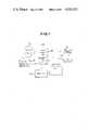
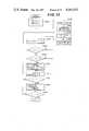
- FIG. 1is a schematic block diagram of the first embodiment of a map display system according to the present invention.
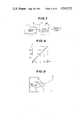
- FIG. 2is a diagram of a display screen of the map display system of FIG. 1;
- FIG. 3is an illustration of a display memory in the system of FIG. 1;
- FIG. 4is an enlarged illustration of the display memory of FIG. 3, in which the contents of each address in the display memory are shown;
- FIG. 5illustrates transformation of the map coordinates
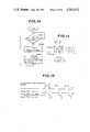
- FIG. 6is a more detailed block diagram of the drive map display system of FIG. 1;
- FIG. 7is a schematic block diagram of the travel direction sensor of FIG. 6;
- FIG. 8is a graph of the relationship of the output of the travel direction sensor of FIG. 7 and the direction of travel of the vehicle;
- FIG. 9is an illustration of the display screen showing the initial state of the display with initial indications of the vehicle position and the destination;
- FIG. 10is a flowchart of the operation of a display control unit in the drive map display system of FIG. 1;
- FIG. 11is a timing chart showing the timing of the transfer of the map data to a display control unit
- FIG. 12is a timing chart showing the relationship between the display control unit operation and a coordinate transformation program executed in a coordinate transforming unit of FIG. 1;
- FIG. 13is a flowchart of a coordinate transformation program executed by the coordinate transforming unit of FIG. 1;
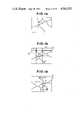
- FIG. 14shows the map as initially stored in a map memory and displayed on the display screen
- FIG. 15is an illustration similar to FIG. 9 showing one way of determining the initial vehicle position and the destination;
- FIG. 16shows a transformed map displayed on the display screen
- FIG. 17is a schematic block diagram of a second embodiment of the drive map display system according to the present invention.
- FIG. 18is a block diagram of the coordinate transforming unit in the drive map display system of FIG. 17;
- FIG. 19shows the sine and cosine values of an offset angle representively produced by a sine signal generator and a cosine signal generator in the drive map display system of FIG. 18;
- FIG. 20is a block diagram of a timing control circuit associated with the coordinate transforming unit of FIG. 18.
- FIG. 1illustrates the general structure of the preferred embodiment of a map display system according to the present invention.
- a road mapis stored in a map memory 10.
- the map memory 10is a digital memory unit for storing digitalized map data. Each map datum represents a corresponding point on a road map.
- the map data in the map memory 10is transferred to a display memory 20 via a coordinate transforming unit 300.
- the display memory 20is adapted to temporarily store the map data to be displayed on a display screen 30.
- the data stored in the display memory 20are read out and transferred to a display control unit 200 via the coordinate transforming unit 300.
- the display control unit 200controls transfer of map data from the map memory 10 to the display memory 20 and from the display memory 20 to the display screen 30.
- a vehicle position sensor unit 100is connected to the display control unit 200.
- the vehicle position sensor unit 100is adapted to detect a distance travelled by the vehicle from a starting point and a travelling direction of the vehicle with respect to the coordinate axis of the map stored in the map memory.
- the vehicle position sensor unit 100produces a travelling distance signal S l and a travelling direction signal S.sub. ⁇ respectively having values representative of the distance travelled by the vehicle and the angular offset of the travelling direction of the vehicle with respect to the map coordinates.
- the vehicle position sensor unit 100is further connected to the coordinate transforming unit 300 for providing the display with coordinate axes aligned with the vehicle direction.
- the travelling direction signal S.sub. ⁇is fed to the coordinate transforming unit 300 so that the map data in the display memory 20 to be displayed on the display screen are transformed such that the map coordinate y-axis lies parallel to the vehicle direction.
- the coordinate transforming unit 300is further connected to an input unit 400 which comprises a pair of joy sticks for controlling cursors, one of which is movable in the vertical direction on the display screen for determining the x-axis coordinate of the vehicle position and a destination in the map coordinates in the map memory.
- the other joy stickis movable in the horizontal direction on the display screen to determine the y-axis coordinate of the vehicle position and the destination. Given the position of the destination determined by the input unit 400 and the vehicle position and travelling direction detected by the vehicle position sensor unit 100, the coordinate transforming unit 300 determines the coordinate axes of the map to be displayed in relation to the map coordinate axes of the map memory.
- the coordinate transforming unit 300sequentially transforms the coordinates of each of the map data in order to convert the coordinates of the map data to the determined display coordinate for display on the display screen 30.
- the vehicle position sensor unit 100periodically produces the travelling distance signal S l and the travelling direction signal S.sub. ⁇ according to the vehicle movement.
- the display control unit 200receives the travelling distance signal S l and the travelling direction signal S.sub. ⁇ and processes them to determine the coordinates of the current vehicle position.
- the display control unit 200produces a vehicle position signal S v representative of the x-coordinate and y-coordinate of the vehicle in the display coordinates at given intervals.
- the vehicle position signal S vthus contains a x-component and a y-component respectively representative of the x-coordinate (x v ) and y-coordinate (y v ) of the vehicle position and is fed to the coordinate transforming unit 300.
- the coordinate transforming unit 300also receives the travelling direction signal S.sub. ⁇ from the vehicle position sensor unit 100. Based on the vehicle position signal S v , a rotation signal S r and the preset destination identified by x- and y-coordinates in the display coordinates, the coordinate transforming unit 300 calculates the displacement of the display center and shifts and rotates the axes of the coordinates to align the y-axis of the coordinates with the vehicle travelling direction. According to this translation and rotation of the display axes, the map data are transformed by the coordinate transforming unit 300.
- the display memory 20consists of a plurality of memory addresses, as shown in FIG. 3. Each address of the display memory 20 consists of 8 bits (1 byte) of storage. Each address holds the data for a horizontal pair of pixels, e.g., p 1 and p 2 .
- FIG. 4shows the content of the address 0 of FIG. 3, in which the first four bits store data for pixel p 1 and the last four bits store data for pixel p 2 .
- the first bit of each four-bit nibbleindicates whether or not the corresponding pixel is to be illuminated at all and the other three bits identify the color to be displayed.
- the addresses of the display memorystore display data for corresponding pixels on the display screen 30.
- the specific example illustrateduses a color Braun tube for displaying the map. Therefore, identification of the color to be displayed requires three bits of color data.
- the map memory 10consists of a plurality of memory addresses storing display data and organized with respect to map coordinates. As disclosed with regard to the display memory, the map memory 10 also stores the map data in sequence as digital data.
- the center of the display mapis taken to be a point halfway between the vehicle position and the destination, and the y-axis of the display coordinates always lies parallel to the travelling direction of the vehicle.
- the origin of the display coordinate system at the center of the displaycan be obtained from the following equations: ##EQU1## Therefore, assuming the coordinates of a map point P a to be x a and y a in the map coordinates of the map memory 10, the coordinates will be transformed with respect to the display coordinates by the following equations: ##EQU2##
- the coordinate transforming unit 300transforms the coordinates of each point of the map to be displayed to the display coordinates as shown in FIG. 5. The transformed
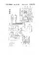
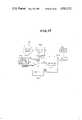
- FIG. 6shows the map display system of the preferred embodiment in more detail for better understanding.
- the vehicle position sensor unit 100comprises a travelling distance sensor 110 and a travelling direction sensor 120.
- the travelling distance sensor 110is disposed opposite the vehicle axle (or a wheel of the vehicle) and generates a pulse for each fixed amount of rotation of the vehicle axle.
- the pulse signalsare fed to a signal shaper 112 and subsequently to the display control unit 200.
- the signals from the shaper 112are vector summed to provide an indication of the vehicle travel distance.
- the travelling direction sensor 120can comprise any of a number of appropriate devices such as a terrestrial magnetic compass, gyrocompass, gyroscope or so forth.
- the travelling direction sensor 120 of the preferred embodimentcomprises a direction sensor 122 and a signal generator 124.
- the direction sensor 122comprises a gyroscope which is well known.
- the output of the sensor 122is inputted to the signal generator 124.
- the signal generator 124produces a travelling direction signal which is an analog signal having a value representative of displacement of the vehicle travelling direction with respect to the North Pole.
- FIG. 8shows the relationship between the angular deviation from true north and the signal value of the travelling direction signal. Namely, as apparent from FIG. 8, the signal value increases as the travelling direction shifts clockwise relative to true north.
- the travelling distance signal (pulses) S l and the travelling direction signal S.sub. ⁇are inputted to an interface 202 and stored in a RAM 206 by a CPU 204.
- the CPU 204operates under program control to calculate the distance travelled by vector summing the distance pulses with respect to the direction data from S.sub. ⁇ . It may be assumed that for relatively small distances, the direction data S.sub. ⁇ is constant so that, for example, ten S l pulses may be summed for a fixed S.sub. ⁇ without appreciable error.
- the CPU 204thus calculates the angle data ⁇ from the signals S.sub. ⁇ and then performs the following sums over a fixed, small number of S l pulses,
- (x i , y i )represents the initial map position of the vehicle, input via the input unit 400 and (x v , y v ) represents the current position of the vehicle.
- These sumsare added to the initial values and new sums are found for an updated ⁇ and the new values are added to the previously calculated (x v , y v ) and so forth, so that the vehicle position is updated continuously.
- the central processing unit 204produces a signal representative of the coordinates (x, y) of the vehicle position in the map coordinates, which signal is hereafter referred to as the vehicle position signal S v .
- the vehicle position signal S vis fed to the coordinate transforming unit 300 via the interface 202.
- the vehicle position signal S vis then inputted to an interface 302 of the coordinate transforming unit 300.
- the travelling direction signal S.sub. ⁇representative of the rotational angle of the display coordinates, is also inputted to the interface 302.
- a central processing unit 304 of the coordinate transforming unit 300executes a coordinate transforming program which is stored in a coordinate transformation program memory (ROM) 306.
- ROMcoordinate transformation program memory
- signals representative of the initial coordinates and the coordinates (x d , y d ) of the destinationare inputted, which signals are referred to hereafter as S i and S d .
- the signals S i and S dare fed to a register 308 in the coordinate transforming unit 300 via the interface 302.
- the central processing unit 304is associated with a timer 310 and periodically executes the coordinate transformation program in accordance with the formulas set forth above.
- the transformed datais stored in the display memory 20 and is periodically updated to take into account the current vehicle position.
- the address locations of the display memory 20correspond to the address locations of the display memory 214 in the display control unit 200. These address locations in turn correspond to the n x m columns and rows for data to be displayed on the display screen 30.
- FIG. 10shows a flowchart for execution by the central processing unit 204.
- bus line 215is checked to see if it is busy. If it is busy, the program loops to repeatedly effect checking at the block 2040 until the bus line 215 becomes available.
- the display program in the program memory 210is executed at a block 2042.
- transformed map datais transferred to the display memory 214 from the display memory 20 and the data are displayed on the display screen 30.
- the display on screen 30 and data transfer operation from the memory 20 to the memory 214may be interleaved line by line updating the display memory 214 without producing visual interference with the screen display data.
- FIG. 11shows the timing of such a line-by-line operation.
- the first display line L 1 of datais transferred from the display memory 20 to the display memory 214 via the interface 302, the bus line 215, the interface 202, and the CPU 204.
- This dataare stored in the memory 214 and displayed by the display controller 212 during the time period between t 1 and t 2 .
- the processis repeated for L 2 transfer during the time period between t 2 and t 3 and L 2 display during the time period between t 3 and t 4 .
- the data transfer between the memory 20 and the memory 214can take place without interleaving the display.
- the central processing unit 204executes the vehicle position calculation program at a block 2044.
- the vehicle position processing programgenerally processes the travelling distance signal S l and travelling direction signal S.sub. ⁇ to obtain the coordinates S v (x v , y v ) of the foregoing vector sum equations. Thereafter, the program in FIG. 10 returns to the initial block 2040.
- the execution of the programs in the central processing unit 204 and the operation of the central processing unit 304 of the coordinate transforming unit 300 of FIG. 6are most clearly illustrated by the timing chart of FIG. 12.
- the timing of the central processing unit operation of the coordinate transforming unit 300is controlled by the timer 310.
- the CPU 304calculates the coordinates of the display data (x a ', y a ') for each point (x a , y a ) of the map and the calculated display data are transferred to the display memory 20.
- the coordinate transformation programis executed in the CPU 304 following which the CPU 204 proceeds to execute steps 2042 and 2044 (see FIG. 10) during the time interval between T 2 and T 3 .
- the time interval between T 2 and T 3is much shorter than the data transformation time T 1 -T 2 , and thus it is shown expanded in FIG. 12. Although not shown, plural cycles of operation of the flowchart of FIG. 10 may be carried out between intervals T 2 and T 4 .
- the central processing unit 304 of the coordinate transforming unit 300executes the coordinate transformation program. As long as the bus line 215 is thus closed, the central processing unit 204 loops in step 2040 to repeatedly check the bus line 215.
- the bus line 215is made available by the CPU 304 upon completion of its current calculation and the data transfer to the display memory 20.
- the display program as set forthis executed in the central processing unit 204 during the interval between T 2 and T 3 .
- the CPU 304reads current input data (S v , S r , S k ) and transforms the map to display coordinate data transformations.
- FIG. 13shows a flowchart of the operation of the coordinate transforming unit 300.
- the map memory 10stores the data to be displayed on the display screen, as shown in FIG. 14.
- the joy stick of the input unit 400is then operated to move the cursors 34 on the display screen to identify the coordinates of the vehicle starting point P and the coordinates of the destination D on the display screen.
- the vehicle position mark Vwhich has a generally pentagon-shaped image pointing in the vehicle travelling direction, will not always lie parallel to the vehicle travelling direction.
- the midpoint coordinates x i and y i with respect to the map coordinates in the map memory 10can be obtained from the following equations: ##EQU3## Further, assuming that the vehicle is travelling south, as shown in FIGS. 14 and 15, the coordinate axes on the display screen must be rotated through 180°, yielding the display image shown in FIG. 16. At the same time, since the midpoint (x i , y i ) in the map coordinates must be the origin of the display coordinates, the display coordinates must be shifted according to the foregoing manner, as shown in FIG. 5.
- the coordinate transforming programis executed under control of the timer 310.
- the initial vehicle position coordinates (x s , y s ) and the destination coordinates (x d , y d )are stored in the register 308 in the coordinate transforming unit 300.
- the current vehicle position coordinates (x v , y v ) and vehicle travelling direction data represented by the travelling direction signal S.sub. ⁇are fed to the RAM 312 via the interface 302.
- the coordinates transforming programis stored in the transforming program memory 306 and used on a time-sharing basis under control of the timer 310.
- the timercontrols the transforming operation according to the timing chart illustrated in FIG. 12.
- the CPU 304 of the coordinate transforming unit 300reads out and executed the coordinates transforming program to transform the coordinates of each point on the map.
- an x-register 314 and a y-register 316are initialized at a block 3002. Then, at a block 3003, the vehicle position signal S v representative of the current vehicle position coordinates x v and y v , and the destination coordinates x d and y d are read out from the RAM 312. Based on the data read out from the RAM 312, the map coordinates of the center of the display is calculated in a block 3004.
- the CPUprocesses the vehicle position signal S v and the destination signal S d according to the equations: ##EQU4##
- the obtained center coordinates x 0 and y 0 in the map coordinatesare then stored in the RAM 312 at a block 3005.
- map data stored in the map memory 10the travelling direction signal S.sub. ⁇ , and the center coordinates x 0 and y 0 are read out.
- the CPU 304transforms the coordinates (x a , y a ) of each point on the map one by one.
- the CPU 304then processes the read data according to the following equations:
- the address of the X-register 314is checked to see if the obtained value x a " is within the range 0 ⁇ x a " ⁇ n-1. If the obtained coordinate x a " is within the range, the obtained coordinate y a " is checked, at a block 3009 to see if the obtained value y a " is within the range 0 ⁇ y a " ⁇ m-1.
- the coordinates (x a ", y a ")are stored in the X-register 314 and Y-register 316 respectively and the map data corresponding to the point (x a , y a ) are transferred to the display memory 20 at the address corresponding to the point (x a ", y a ") at a block 3010.
- the value of the X-register 314is incremented by 1, at a block 3012. Then, the X-coordinate value is checked to see whether it is larger than (n-1) at a block 3014. If the condition in block 3014 is satisfied, the value of X is reset to zero and value Y representative of the coordinate stored in the Y-register is incremented by 1, at a block 3016. Thus, the value Y is checked to see if it is larger than (m-1) at a block 3018 and, if so, the coordinates transformation program ends.
- the programjumps to the block 3012 to increment the value X and to proceed to block 3014.
- the addresses (x a ", y a ")are not written in the X-register and Y-register 314 and 316.
- the programreturns to the block 3006 to repeat execution of the blocks 3007 to 3014.
- the register value Xbecomes greater than (n-1)
- the display memory 20shifts to the next adjacent row which corresponds to the register value Y being incremented by 1 and the register value X being initialized to re-start the data transforming operation from the first column in the next row of the display memory address, at the block 3016. If the condition in the block 3018 is not satisfied, the program returns to the block 3006 to perform the transforming operation for the next row.
- the bus line 215opens to permit the map data in the display memory 20 to be transferred to update the map data in the display memory 214 in the display control unit 200 as shown in FIG. 11.
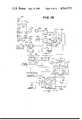
- FIG. 17illustrates the general structure of another embodiment of a map display system according to the present invention.
- the coordinate transforming unit using the microcomputer in the foregoing embodimentis replaced by a coordinate transforming unit 500.
- the components of FIG. 17are similar to the corresponding components of FIG. 1.
- the road mapis stored in a map memory 12.
- the map data in the map memory 12is transferred to the display memory 22 via a coordinate transforming unit 500.
- the display memory 22is adapted to temporarily store the map data to be displayed on a display screen 32.
- the data stored in the display memory 22is read out and transferred to a display control unit 220 via the coordinate transforming unit 500.
- the display control unit 220controls transfer of map data from the map memory 12 to the display memory for display on the display screen 32.
- a vehicle position sensor unit 150is connected to the display control unit 220.
- the vehicle position sensor unit 150is adapted to detect the distance travelled by the vehicle from a starting point and the travelling direction of the vehicle with respect to the coordinate system of the map stored in the map memory 12.
- the vehicle position sensor unit 150produces a travelling distance signal S l and a travelling direction signal S.sub. ⁇ respectively having values representative of the travelling distance by the vehicle and the angle of offset of the vehicle travelling direction with respect to the map coordinates.
- the vehicle position sensor unit 150is further connected to a coordinate rotation signal generator 42 to send the travelling direction signal S.sub. ⁇ .
- the travelling direction signal S.sub. ⁇is fed to the coordinate transforming unit 500 for use in rotating the coordinate axes of the display memory data such that the y-axis thereof lies parallel to the direction of the travel of the vehicle.
- the coordinate transforming unit 500is further connected to an input unit 450 for inputting the coordinates of the position of the vehicle and its destination. Based on the predetermined coordinates of the vehicle position and its destination, the initial center of the display is determined. With the initial display center determined and the vehicle direction detected by the vehicle position sensor unit 150, the coordinate transforming unit 500 determines the orientation of the coordinate axes of the map to be displayed in relation to the coordinate system of the map memory 12.
- the coordinate transforming unit 500sequentially transforms all of the map points in order to adapt the coordinates of each map point to the determined coordinate axes for display on the display screen 32.
- the vehicle position sensor unit 150sequentially produces the travelling distance pulses S l and the travelling direction signal S.sub. ⁇ .
- the display control unit 220receives the travelling distance signal S l and the travelling direction signal S.sub. ⁇ and processes them to determine the coordinates of the present vehicle position.
- the display control unit 220produces a vehicle position signal S v representative of the x- and y-coordinates of the vehicle in the display coordinates at given intervals.
- the vehicle position signal S vthus contains an x-component and a y-component respectively representative of the x-coordinate (x v ) and the y-coordinate (y v ) of the vehicle position and is fed to the coordinate transforming unit 500.
- the coordinate transforming unit 500also receives the rotation signal S r from the coordinates rotation signal generator 42. Based on the vehicle position signal S v and rotation signal S r , the coordinate transforming unit 500 performs a data transformation to displace the display center and thereby shift the display coordinates and rotate the axes of the coordinates to align the y-axis of the coordinates parallel to the vehicle travelling direction.
- FIG. 18is a detailed block diagram of the circuitry of the coordinate transforming unit 500 of FIG. 17.
- a number of signalsare generated for input to the coordinate transforming unit 500.
- the signalsinclude a vehicle position signal S v produced by the display control unit 200, the initial vehicle position signal S i produced by the input unit 400, and the vehicle travelling direction signal S.sub. ⁇ produced by the vehicle position sensor unit 100.
- the vehicle position signal S v x-component x v and y-component y v produced by the display control unit 200are sent to corresponding OR gates 501 and 502.
- the initial vehicle position signal S i x-component (x i ) and y-component (y i ) produced by the input unit 400are fed to the OR gates 501 and 502.
- the OR gates 501 and 502are respectively connected to adders 503 and 504.
- the x-component (x d ) and y-component (y d ) of a destination signal S d produced by the input unit 400are conducted to the adders 503 and 504, respectively. Therefore, the adder 503 and 504 respectively obtain sums of x v or x i and x d and y v or y i and y d .
- the outputs of the adders 503 and 504are fed to dividers 505 and 506. In the divider 505 and 506, the sums obtained by the adders 503 and 504 are divided by 2 to obtain the coordinate values corresponding to the point halfway between the vehicle position and the destination. Therefore, the outputs of the dividers 505 and 506 respectively represent x-component x i and y-component y i of the point halfway between the vehicle position and the destination.
- the travelling direction signal S.sub. ⁇is fed to a cosine generator 526 and a sine generator 527.
- the cosine generator 526 and sine generator 527have input-output characteristics as shown by the graphs in FIG. 19.
- the characteristics of the curves A (sin ⁇ ) and B (cos ⁇ )can be realized by a square wave approximation circuit including diodes. Since the curves A and B have an offset value of E/2, the corrected cos ⁇ and sin ⁇ can be obtained by subtracting the digital value corresponding to E/2 by subtractors 503 and 531 after their digital conversion.
- subtractors 532 and 533calculate (x a -x i ) and (y a -y i ) for use in the equation:
- Multipliers 534, 536, and 537respectively calculate the terms (x a -x i ) cos ⁇ , (x a -y i ) sin ⁇ , (y a -y i ) cos ⁇ and (y a -y i ) sin ⁇ in the above equations.
- subtractors 538 and 539output
- the coordinates (x a ", y a ") in the display coordinate systemare then stored in an X a "-register 544 and a Y a "-register 545, respectively.
- the coordinate values x a " and y a "are checked by limit circuits 546 and 547 respectively whether the obtained transformed coordinates (x a ", y a ") are within the extent, i.e. the display screen of "m” rows and "n” columns.
- Only the coordinates (x a ", y a ") falling within the display screenare converted to a memory address by an address convertor 549 so as to specify the corresponding address in the display memory 22 through an address-bus switch circuit 550.
- a memory recording signal generator 548outputs a record command for recording the data in the address in the display memory 22 specified by the address signal from the address convertor 549.
- a read-out meanscomprising an X counter 551 which counts scanning pulses S scan applied with a constant period and outputs a value x a , a discriminator 553 which discriminates whether the count value x a repeatedly outputted coincides with a predetermined value and outputs a pulse when the count coincides with the predetermined value, a Y counter 552 which counts the pulses from the discriminator 553 and outputs a value y a , and an OR gate 54 which resets the X counter 551 in response to a pulse from the discriminator 553 or a reset pulse S reset .
- the Y counter 552is also reset by the reset pulse S reset .
- a means for generating the reset pulse S reset and the scanning pulse S scan to read out the data stored in the map memory 12is constructed as shown in FIG. 20.
- the reference numeral 557denotes a timer which generates a pulse signal which switches at regular intervals between a mode for transforming and recording the data stored in the map memory 12 into the coordinates of the display memory 22, and another mode for displaying the data stored in the display memory 22 on the display screen 32.
- a flip-flop 558is actuated by the output pulse from the timer 557, thereby switching between the transforming and recording modes.
- the flip-flop 558is reset by the output pulse, thereby switching to the mode for display.
- the flip-flop 558Whenever the flip-flop 558 is actuated, it outputs a signal as an address-bus switching signal to the address-bus switch circuit 550 and a latch 556 for detecting and latching the data to be displayed so as to allow for the recording of the data from the map memory 12 into the display memory 22 at the address specified by counters 546 and 545. In this manner, the data bits of the map memory 12 are stored at addresses which correspond to the transferred coordinates (x a ", y a "). The data in the display memory 22 is thus effectively translated and rotated with respect to the data in the map memory 12.
- a pulse generator 559is actuated by the set output from the flip-flop 558, thereby generating a plurality of scanning pulses S scan at a constant period, which are conducted to the display control unit 220 to activate the scanning beam of the display screen 32.
- a down-counter 560decrements a value set by a pre-set value setting circuit 561 (when the display screen is "m" rows and "n" columns, the set value is "m ⁇ n-1") in accordance with the scanning pulse S scan .
- a signalis sent to a delay circuit 562 which outputs a pulse which is delayed by a predetermined period to the flip-flop 558 so as to reset it and switch to the mode for displaying.
- the predetermined delay periods in the delay circuit 562permits time for completion of the recording of the data in the display memory 22.
Landscapes
- Engineering & Computer Science (AREA)
- Radar, Positioning & Navigation (AREA)
- Remote Sensing (AREA)
- Physics & Mathematics (AREA)
- General Physics & Mathematics (AREA)
- Theoretical Computer Science (AREA)
- Automation & Control Theory (AREA)
- Mathematical Physics (AREA)
- Computer Graphics (AREA)
- Business, Economics & Management (AREA)
- Educational Administration (AREA)
- Educational Technology (AREA)
- Navigation (AREA)
- Processing Or Creating Images (AREA)
- Traffic Control Systems (AREA)
- Instructional Devices (AREA)
Abstract
Description
x.sub.v =s.sub.i +{(S.sub.l ·cos θ)x.sub.v =y.sub.i +{(S.sub.l ·sin θ)X.sub.a "=(X.sub.a -X.sub.o) cos θ+(Y.sub.a -Y.sub.o) sin θ
Y.sub.a "=(X.sub.a -X.sub.o) sin θ+(Y.sub.a -Y.sub.o) cos θ
x.sub.a "=(x.sub.a -x.sub.i) cos θ+(y.sub.a -y.sub.i) cos θ
y.sub.a "=(x.sub.a -x.sub.i) sin θ+(y.sub.a -y.sub.i) cos θ
x.sub.a "=(x.sub.a -x.sub.i) cos θ+(y.sub.a -y.sub.i) sin θ and
y.sub.a "=(x.sub.a -x.sub.i) sin θ+(y.sub.a -y.sub.i) cos θ.
Claims (12)
Applications Claiming Priority (2)
| Application Number | Priority Date | Filing Date | Title |
|---|---|---|---|
| JP56-70781 | 1981-05-13 | ||
| JP56070781AJPS57186111A (en) | 1981-05-13 | 1981-05-13 | Map display device for vehicle |
Publications (1)
| Publication Number | Publication Date |
|---|---|
| US4543572Atrue US4543572A (en) | 1985-09-24 |
Family
ID=13441402
Family Applications (1)
| Application Number | Title | Priority Date | Filing Date |
|---|---|---|---|
| US06/373,168Expired - LifetimeUS4543572A (en) | 1981-05-13 | 1982-04-29 | Road map display system with indications of a vehicle position and destination |
Country Status (4)
| Country | Link |
|---|---|
| US (1) | US4543572A (en) |
| JP (1) | JPS57186111A (en) |
| DE (1) | DE3217880A1 (en) |
| GB (1) | GB2102259B (en) |
Cited By (51)
| Publication number | Priority date | Publication date | Assignee | Title |
|---|---|---|---|---|
| US4628456A (en)* | 1981-08-07 | 1986-12-09 | Alps Electric Co., Ltd. | Course guidance system |
| US4638438A (en)* | 1983-05-23 | 1987-01-20 | Hitachi, Ltd. | Navigation apparatus for automotive |
| US4675676A (en)* | 1983-03-09 | 1987-06-23 | Nippondenso Co. Ltd. | Map display system |
| US4677450A (en)* | 1984-03-19 | 1987-06-30 | Mitsubishi Denki Kabushiki Kaisha | Automotive navigation system |
| US4677563A (en)* | 1984-04-27 | 1987-06-30 | Mitsubishi Denki Kabushiki Kaisha | Automotive navigation system |
| US4677561A (en)* | 1984-04-28 | 1987-06-30 | Mitsubishi Denki Kabushiki Kaisha | Automotive navigation system |
| US4677562A (en)* | 1984-05-15 | 1987-06-30 | Mitsubishi Denki Kabushiki Kaisha | Automotive navigation system |
| US4716404A (en)* | 1983-04-01 | 1987-12-29 | Hitachi, Ltd. | Image retrieval method and apparatus using annotations as guidance information |
| US4718025A (en)* | 1985-04-15 | 1988-01-05 | Centec Corporation | Computer management control system |
| US4737927A (en)* | 1985-04-30 | 1988-04-12 | Nippondenso Co., Ltd. | Map display apparatus |
| US4737773A (en)* | 1984-09-04 | 1988-04-12 | Nec Corporation | Graphical display apparatus having a coordinate correction circuit |
| US4737916A (en)* | 1985-04-30 | 1988-04-12 | Nippondenso Co., Ltd. | Electronic map display system |
| US4744033A (en)* | 1985-04-30 | 1988-05-10 | Nippondenso Co., Ltd. | Electronic display system |
| US4758959A (en)* | 1984-08-14 | 1988-07-19 | U.S. Philips Corporation | Vehicle navigation system provided with an adaptive inertial navigation system based on the measurement of the speed and lateral acceleration of the vehicle and provided with a correction unit for correcting the measured values |
| US4761742A (en)* | 1985-04-26 | 1988-08-02 | Nippondenso Co., Ltd. | Guiding spot display apparatus |
| US4763268A (en)* | 1985-04-23 | 1988-08-09 | Mitsubishi Denki Kabushiki Kaisha | Direction display apparatus |
| US4780717A (en)* | 1983-03-25 | 1988-10-25 | Nippondenso Co., Ltd. | Electronic map display system for use on vehicle |
| US4814989A (en)* | 1985-05-30 | 1989-03-21 | Robert Bosch Gmbh | Navigation method for vehicles |
| US4825381A (en)* | 1987-03-31 | 1989-04-25 | Rockwell International Corporation | Moving map display |
| US4845645A (en)* | 1987-08-28 | 1989-07-04 | The United States Of America As Represented By The Secretary Of The Air Force | Sequential rapid communication visual displays |
| US5016007A (en)* | 1985-04-19 | 1991-05-14 | Honda Giken Kogyo Kabushiki Kaisha | Apparatus for displaying travel path |
| US5274387A (en)* | 1990-06-06 | 1993-12-28 | Mazda Motor Corporation | Navigation apparatus for vehicles |
| US5672840A (en)* | 1994-12-21 | 1997-09-30 | Trw Inc. | Method and apparatus for automatically orienting a computer display |
| US5719765A (en)* | 1995-08-07 | 1998-02-17 | Snap-On Technologies, Inc. | Real-time scrolling drive-trace display for a vehicle engine analyzer |
| US5778333A (en)* | 1994-09-02 | 1998-07-07 | Nippondenso Co., Ltd. | Boundary route setting device for a map display system |
| US5790975A (en)* | 1989-12-13 | 1998-08-04 | Pioneer Electronic Corporation | Onboard navigational system |
| US5848373A (en)* | 1994-06-24 | 1998-12-08 | Delorme Publishing Company | Computer aided map location system |
| US5862511A (en)* | 1995-12-28 | 1999-01-19 | Magellan Dis, Inc. | Vehicle navigation system and method |
| US5925091A (en)* | 1995-06-12 | 1999-07-20 | Alpine Electronics, Inc. | Method and apparatus for drawing a map for a navigation system |
| US5977961A (en)* | 1996-06-19 | 1999-11-02 | Sun Microsystems, Inc. | Method and apparatus for amplitude band enabled addressing arrayed elements |
| US5991692A (en)* | 1995-12-28 | 1999-11-23 | Magellan Dis, Inc. | Zero motion detection system for improved vehicle navigation system |
| US5999879A (en)* | 1996-04-26 | 1999-12-07 | Pioneer Electronic Corporation | Navigation apparatus with shape change display function |
| US6029111A (en)* | 1995-12-28 | 2000-02-22 | Magellan Dis, Inc. | Vehicle navigation system and method using GPS velocities |
| US6122591A (en)* | 1998-08-18 | 2000-09-19 | Pomerantz; David | Taxi trip meter system with indication of fare and distance violations |
| US6157375A (en)* | 1998-06-30 | 2000-12-05 | Sun Microsystems, Inc. | Method and apparatus for selective enabling of addressable display elements |
| US6266613B1 (en) | 1995-10-04 | 2001-07-24 | Aisin Aw Co., Ltd. | Navigation apparatus for a vehicle |
| US6308134B1 (en) | 1996-12-27 | 2001-10-23 | Magellan Dis, Inc. | Vehicle navigation system and method using multiple axes accelerometer |
| US6408307B1 (en) | 1995-01-11 | 2002-06-18 | Civix-Ddi, Llc | System and methods for remotely accessing a selected group of items of interest from a database |
| US6456281B1 (en) | 1999-04-02 | 2002-09-24 | Sun Microsystems, Inc. | Method and apparatus for selective enabling of Addressable display elements |
| US6573842B2 (en)* | 2000-10-06 | 2003-06-03 | Matsushita Electric Industrial Co., Ltd. | Map display device, map display method, and computer program for use in map display device |
| US20070094094A1 (en)* | 1999-02-26 | 2007-04-26 | Skyline Acquisition Corporation | Sending three-dimensional images over a network |
| US20070124066A1 (en)* | 2003-10-21 | 2007-05-31 | Navitime Japan Co.,Ltd. | Navigation device, navigation method, and program |
| US20120011457A1 (en)* | 2009-03-20 | 2012-01-12 | Koninklijke Philips Electronics N.V. | Visualizing a view of a scene |
| US8142304B2 (en) | 2000-12-19 | 2012-03-27 | Appalachian Technology, Llc | Golf round data system golf club telemetry |
| US8172702B2 (en) | 2000-06-16 | 2012-05-08 | Skyhawke Technologies, Llc. | Personal golfing assistant and method and system for graphically displaying golf related information and for collection, processing and distribution of golf related data |
| US8221269B2 (en) | 2000-06-16 | 2012-07-17 | Skyhawke Technologies, Llc | Personal golfing assistant and method and system for graphically displaying golf related information and for collection, processing and distribution of golf related data |
| CN103185586A (en)* | 2011-12-30 | 2013-07-03 | 上海博泰悦臻电子设备制造有限公司 | Map display method, apparatus for controlling map display and navigation apparatus |
| CN103185593A (en)* | 2011-12-30 | 2013-07-03 | 上海博泰悦臻电子设备制造有限公司 | Navigation method and navigation device |
| CN107168360A (en)* | 2013-07-05 | 2017-09-15 | 深圳市大疆创新科技有限公司 | The flight householder method and device of unmanned vehicle |
| CN111009156A (en)* | 2014-10-17 | 2020-04-14 | 索尼公司 | Test vehicle control device, control method and computer program |
| US10627816B1 (en)* | 2014-08-29 | 2020-04-21 | Waymo Llc | Change detection using curve alignment |
Families Citing this family (25)
| Publication number | Priority date | Publication date | Assignee | Title |
|---|---|---|---|---|
| DE3204135C2 (en)* | 1982-02-06 | 1987-01-08 | Honeywell Regelsysteme GmbH, 6050 Offenbach | Device for simulating the free view by means of an optical device |
| JPS58142383A (en)* | 1982-02-18 | 1983-08-24 | 本田技研工業株式会社 | figure rotation device |
| JPS5965713A (en)* | 1982-10-07 | 1984-04-14 | Canon Inc | Display device of picture information |
| JPS5963377U (en)* | 1982-10-21 | 1984-04-26 | パイオニア株式会社 | map display device |
| JPS59145000A (en)* | 1983-02-07 | 1984-08-20 | 本田技研工業株式会社 | navigator device |
| JPS59164583A (en)* | 1983-03-09 | 1984-09-17 | 株式会社デンソー | Map display unit |
| DE3345520A1 (en)* | 1983-12-16 | 1985-02-07 | Audi Nsu Auto Union Ag, 7107 Neckarsulm | Method for inputting coordinates |
| JPH0625909B2 (en)* | 1984-10-22 | 1994-04-06 | エタツク インコ−ポレ−テツド | Map display device and method |
| JPS61156276A (en)* | 1984-12-28 | 1986-07-15 | リズム時計工業株式会社 | Running track display unit for vehicle |
| JPS61166583A (en)* | 1985-01-18 | 1986-07-28 | リズム時計工業株式会社 | Running track display unit for vehicle |
| JPS61194472A (en)* | 1985-02-25 | 1986-08-28 | パイオニア株式会社 | Navigation system |
| JPS61209316A (en)* | 1985-03-14 | 1986-09-17 | Nissan Motor Co Ltd | Vehicle route guidance device |
| JPS61216098A (en)* | 1985-03-20 | 1986-09-25 | 日産自動車株式会社 | Vehicle route guidance device |
| DE3512127A1 (en)* | 1985-04-03 | 1986-10-16 | Robert Bosch Gmbh, 7000 Stuttgart | LOCATION AND NAVIGATION SYSTEM FOR AGRICULTURAL VEHICLES |
| JPH0650560B2 (en)* | 1985-04-03 | 1994-06-29 | 日産自動車株式会社 | Vehicle route guidance device |
| JPH0712895Y2 (en)* | 1988-02-26 | 1995-03-29 | 日産自動車株式会社 | Current location display device for vehicles |
| GB2220826A (en)* | 1988-07-06 | 1990-01-17 | British Aerospace | A force/torque display for robotic arm |
| DE4119304A1 (en)* | 1991-06-12 | 1992-12-17 | Erkelenz Thomas | Road network information display system for motor vehicle - uses data entered on some form of storage medium processed to provide display on VDU screen |
| JPH05257436A (en)* | 1992-03-13 | 1993-10-08 | A T R Shichokaku Kiko Kenkyusho:Kk | Map information display device |
| JPH0743638B2 (en)* | 1992-10-19 | 1995-05-15 | 株式会社日立製作所 | Drawing display method and apparatus |
| JPH074979A (en)* | 1993-06-18 | 1995-01-10 | Pioneer Electron Corp | Navigation apparatus |
| DE69428505T2 (en)* | 1993-12-27 | 2002-06-06 | Aisin Aw Co., Ltd. | Map display system |
| US6092076A (en)* | 1998-03-24 | 2000-07-18 | Navigation Technologies Corporation | Method and system for map display in a navigation application |
| US6163749A (en)* | 1998-06-05 | 2000-12-19 | Navigation Technologies Corp. | Method and system for scrolling a map display in a navigation application |
| US10317220B2 (en)* | 2017-08-30 | 2019-06-11 | Aptiv Technologies Limited | Alignment of multiple digital maps used in an automated vehicle |
Citations (27)
| Publication number | Priority date | Publication date | Assignee | Title |
|---|---|---|---|---|
| US3521228A (en)* | 1967-01-13 | 1970-07-21 | Kaiser Aerospace & Electronics | Course center line generator for aircraft displays |
| US3520994A (en)* | 1967-01-12 | 1970-07-21 | Kaiser Aerospace & Electronics | Combination raster and calligraphic scanning techniques for aircraft displays |
| US3668622A (en)* | 1970-05-21 | 1972-06-06 | Boeing Co | Flight management display |
| US3760360A (en)* | 1971-11-01 | 1973-09-18 | E Systems Inc | Matrix switch |
| US3783542A (en)* | 1972-11-10 | 1974-01-08 | Atkins & Merrill | Map display system |
| US3821729A (en)* | 1972-03-24 | 1974-06-28 | Siemens Ag | Arrangement for controlling the orientation of characters on a display device utilizing angle defining data syllables and data addition for such syllables |
| US3906197A (en)* | 1973-03-09 | 1975-09-16 | Nat Res Dev | Apparatus and methods for computer graphics |
| US3925765A (en)* | 1973-10-29 | 1975-12-09 | Hughes Aircraft Co | Digital raster rotator |
| US3967266A (en)* | 1974-09-16 | 1976-06-29 | Hewlett-Packard Company | Display apparatus having improved cursor enhancement |
| US4024493A (en)* | 1974-06-07 | 1977-05-17 | Ingels George W | Apparatus for motor vehicle position indication |
| US4086632A (en)* | 1976-09-27 | 1978-04-25 | The Boeing Company | Area navigation system including a map display unit for establishing and modifying navigation routes |
| US4138726A (en)* | 1976-07-02 | 1979-02-06 | Thomson-Csf | Airborne arrangement for displaying a moving map |
| US4149148A (en)* | 1977-04-19 | 1979-04-10 | Sperry Rand Corporation | Aircraft flight instrument display system |
| US4225929A (en)* | 1978-03-10 | 1980-09-30 | Taito Corporation | Code converter circuitry system for selectively rotating a video display picture |
| US4267555A (en)* | 1979-06-29 | 1981-05-12 | International Business Machines Corporation | Rotatable raster scan display |
| US4271476A (en)* | 1979-07-17 | 1981-06-02 | International Business Machines Corporation | Method and apparatus for rotating the scan format of digital images |
| US4305057A (en)* | 1979-07-19 | 1981-12-08 | Mcdonnell Douglas Corporation | Concave quadratic aircraft attitude reference display system |
| US4312577A (en)* | 1979-08-13 | 1982-01-26 | Fitzgerald J Vincent | Motor vehicle map display system |
| US4317114A (en)* | 1980-05-12 | 1982-02-23 | Cromemco Inc. | Composite display device for combining image data and method |
| EP0059435A2 (en)* | 1981-03-04 | 1982-09-08 | Nissan Motor Co., Ltd. | Image display device |
| DE3213630A1 (en)* | 1981-04-13 | 1982-11-18 | Nissan Motor Co., Ltd., Yokohama, Kanagawa | ROAD MAP DISPLAY SYSTEM WITH SPECIFICATION OF A VEHICLE POSITION |
| US4360876A (en)* | 1979-07-06 | 1982-11-23 | Thomson-Csf | Cartographic indicator system |
| US4366475A (en)* | 1980-02-23 | 1982-12-28 | Fujitsu Fanuc Limited | Image display system |
| US4384286A (en)* | 1980-08-29 | 1983-05-17 | General Signal Corp. | High speed graphics |
| US4398171A (en)* | 1980-02-26 | 1983-08-09 | Dahan Pierre Louis | Video system for plotting and transmitting video traffic information |
| US4400727A (en)* | 1981-11-27 | 1983-08-23 | The Bendix Corporation | Moving map display |
| US4400780A (en)* | 1979-04-27 | 1983-08-23 | Furuno Electric Co., Ltd. | Moving body track indicator system |
- 1981
- 1981-05-13JPJP56070781Apatent/JPS57186111A/enactiveGranted
- 1982
- 1982-04-29USUS06/373,168patent/US4543572A/ennot_activeExpired - Lifetime
- 1982-05-06GBGB08213180Apatent/GB2102259B/ennot_activeExpired
- 1982-05-12DEDE19823217880patent/DE3217880A1/ennot_activeCeased
Patent Citations (28)
| Publication number | Priority date | Publication date | Assignee | Title |
|---|---|---|---|---|
| US3520994A (en)* | 1967-01-12 | 1970-07-21 | Kaiser Aerospace & Electronics | Combination raster and calligraphic scanning techniques for aircraft displays |
| US3521228A (en)* | 1967-01-13 | 1970-07-21 | Kaiser Aerospace & Electronics | Course center line generator for aircraft displays |
| US3668622A (en)* | 1970-05-21 | 1972-06-06 | Boeing Co | Flight management display |
| US3760360A (en)* | 1971-11-01 | 1973-09-18 | E Systems Inc | Matrix switch |
| US3821729A (en)* | 1972-03-24 | 1974-06-28 | Siemens Ag | Arrangement for controlling the orientation of characters on a display device utilizing angle defining data syllables and data addition for such syllables |
| US3783542A (en)* | 1972-11-10 | 1974-01-08 | Atkins & Merrill | Map display system |
| US3906197A (en)* | 1973-03-09 | 1975-09-16 | Nat Res Dev | Apparatus and methods for computer graphics |
| US3925765A (en)* | 1973-10-29 | 1975-12-09 | Hughes Aircraft Co | Digital raster rotator |
| US4024493A (en)* | 1974-06-07 | 1977-05-17 | Ingels George W | Apparatus for motor vehicle position indication |
| US3967266A (en)* | 1974-09-16 | 1976-06-29 | Hewlett-Packard Company | Display apparatus having improved cursor enhancement |
| US4138726A (en)* | 1976-07-02 | 1979-02-06 | Thomson-Csf | Airborne arrangement for displaying a moving map |
| US4086632A (en)* | 1976-09-27 | 1978-04-25 | The Boeing Company | Area navigation system including a map display unit for establishing and modifying navigation routes |
| US4149148A (en)* | 1977-04-19 | 1979-04-10 | Sperry Rand Corporation | Aircraft flight instrument display system |
| US4225929A (en)* | 1978-03-10 | 1980-09-30 | Taito Corporation | Code converter circuitry system for selectively rotating a video display picture |
| US4400780A (en)* | 1979-04-27 | 1983-08-23 | Furuno Electric Co., Ltd. | Moving body track indicator system |
| US4267555A (en)* | 1979-06-29 | 1981-05-12 | International Business Machines Corporation | Rotatable raster scan display |
| US4360876A (en)* | 1979-07-06 | 1982-11-23 | Thomson-Csf | Cartographic indicator system |
| US4271476A (en)* | 1979-07-17 | 1981-06-02 | International Business Machines Corporation | Method and apparatus for rotating the scan format of digital images |
| US4305057A (en)* | 1979-07-19 | 1981-12-08 | Mcdonnell Douglas Corporation | Concave quadratic aircraft attitude reference display system |
| US4312577A (en)* | 1979-08-13 | 1982-01-26 | Fitzgerald J Vincent | Motor vehicle map display system |
| US4366475A (en)* | 1980-02-23 | 1982-12-28 | Fujitsu Fanuc Limited | Image display system |
| US4398171A (en)* | 1980-02-26 | 1983-08-09 | Dahan Pierre Louis | Video system for plotting and transmitting video traffic information |
| US4317114A (en)* | 1980-05-12 | 1982-02-23 | Cromemco Inc. | Composite display device for combining image data and method |
| US4384286A (en)* | 1980-08-29 | 1983-05-17 | General Signal Corp. | High speed graphics |
| EP0059435A2 (en)* | 1981-03-04 | 1982-09-08 | Nissan Motor Co., Ltd. | Image display device |
| DE3213630A1 (en)* | 1981-04-13 | 1982-11-18 | Nissan Motor Co., Ltd., Yokohama, Kanagawa | ROAD MAP DISPLAY SYSTEM WITH SPECIFICATION OF A VEHICLE POSITION |
| GB2100001A (en)* | 1981-04-13 | 1982-12-15 | Nissan Motor | Road map display system |
| US4400727A (en)* | 1981-11-27 | 1983-08-23 | The Bendix Corporation | Moving map display |
Cited By (73)
| Publication number | Priority date | Publication date | Assignee | Title |
|---|---|---|---|---|
| US4628456A (en)* | 1981-08-07 | 1986-12-09 | Alps Electric Co., Ltd. | Course guidance system |
| US4675676A (en)* | 1983-03-09 | 1987-06-23 | Nippondenso Co. Ltd. | Map display system |
| US4780717A (en)* | 1983-03-25 | 1988-10-25 | Nippondenso Co., Ltd. | Electronic map display system for use on vehicle |
| US4716404A (en)* | 1983-04-01 | 1987-12-29 | Hitachi, Ltd. | Image retrieval method and apparatus using annotations as guidance information |
| US4638438A (en)* | 1983-05-23 | 1987-01-20 | Hitachi, Ltd. | Navigation apparatus for automotive |
| US4677450A (en)* | 1984-03-19 | 1987-06-30 | Mitsubishi Denki Kabushiki Kaisha | Automotive navigation system |
| US4677563A (en)* | 1984-04-27 | 1987-06-30 | Mitsubishi Denki Kabushiki Kaisha | Automotive navigation system |
| US4677561A (en)* | 1984-04-28 | 1987-06-30 | Mitsubishi Denki Kabushiki Kaisha | Automotive navigation system |
| US4677562A (en)* | 1984-05-15 | 1987-06-30 | Mitsubishi Denki Kabushiki Kaisha | Automotive navigation system |
| US4758959A (en)* | 1984-08-14 | 1988-07-19 | U.S. Philips Corporation | Vehicle navigation system provided with an adaptive inertial navigation system based on the measurement of the speed and lateral acceleration of the vehicle and provided with a correction unit for correcting the measured values |
| US4737773A (en)* | 1984-09-04 | 1988-04-12 | Nec Corporation | Graphical display apparatus having a coordinate correction circuit |
| US4718025A (en)* | 1985-04-15 | 1988-01-05 | Centec Corporation | Computer management control system |
| US5016007A (en)* | 1985-04-19 | 1991-05-14 | Honda Giken Kogyo Kabushiki Kaisha | Apparatus for displaying travel path |
| US4763268A (en)* | 1985-04-23 | 1988-08-09 | Mitsubishi Denki Kabushiki Kaisha | Direction display apparatus |
| US4761742A (en)* | 1985-04-26 | 1988-08-02 | Nippondenso Co., Ltd. | Guiding spot display apparatus |
| US4737916A (en)* | 1985-04-30 | 1988-04-12 | Nippondenso Co., Ltd. | Electronic map display system |
| US4737927A (en)* | 1985-04-30 | 1988-04-12 | Nippondenso Co., Ltd. | Map display apparatus |
| US4744033A (en)* | 1985-04-30 | 1988-05-10 | Nippondenso Co., Ltd. | Electronic display system |
| US4814989A (en)* | 1985-05-30 | 1989-03-21 | Robert Bosch Gmbh | Navigation method for vehicles |
| US4825381A (en)* | 1987-03-31 | 1989-04-25 | Rockwell International Corporation | Moving map display |
| US4845645A (en)* | 1987-08-28 | 1989-07-04 | The United States Of America As Represented By The Secretary Of The Air Force | Sequential rapid communication visual displays |
| US5790975A (en)* | 1989-12-13 | 1998-08-04 | Pioneer Electronic Corporation | Onboard navigational system |
| US5274387A (en)* | 1990-06-06 | 1993-12-28 | Mazda Motor Corporation | Navigation apparatus for vehicles |
| US5848373A (en)* | 1994-06-24 | 1998-12-08 | Delorme Publishing Company | Computer aided map location system |
| US5778333A (en)* | 1994-09-02 | 1998-07-07 | Nippondenso Co., Ltd. | Boundary route setting device for a map display system |
| US5672840A (en)* | 1994-12-21 | 1997-09-30 | Trw Inc. | Method and apparatus for automatically orienting a computer display |
| US6415291B2 (en) | 1995-01-11 | 2002-07-02 | Civix-Ddi, Llc | System and methods for remotely accessing a selected group of items of interest from a database |
| US6408307B1 (en) | 1995-01-11 | 2002-06-18 | Civix-Ddi, Llc | System and methods for remotely accessing a selected group of items of interest from a database |
| US5925091A (en)* | 1995-06-12 | 1999-07-20 | Alpine Electronics, Inc. | Method and apparatus for drawing a map for a navigation system |
| US5719765A (en)* | 1995-08-07 | 1998-02-17 | Snap-On Technologies, Inc. | Real-time scrolling drive-trace display for a vehicle engine analyzer |
| US6266613B1 (en) | 1995-10-04 | 2001-07-24 | Aisin Aw Co., Ltd. | Navigation apparatus for a vehicle |
| US6029111A (en)* | 1995-12-28 | 2000-02-22 | Magellan Dis, Inc. | Vehicle navigation system and method using GPS velocities |
| US5991692A (en)* | 1995-12-28 | 1999-11-23 | Magellan Dis, Inc. | Zero motion detection system for improved vehicle navigation system |
| US5862511A (en)* | 1995-12-28 | 1999-01-19 | Magellan Dis, Inc. | Vehicle navigation system and method |
| US5999879A (en)* | 1996-04-26 | 1999-12-07 | Pioneer Electronic Corporation | Navigation apparatus with shape change display function |
| US5977961A (en)* | 1996-06-19 | 1999-11-02 | Sun Microsystems, Inc. | Method and apparatus for amplitude band enabled addressing arrayed elements |
| US6308134B1 (en) | 1996-12-27 | 2001-10-23 | Magellan Dis, Inc. | Vehicle navigation system and method using multiple axes accelerometer |
| US6628273B1 (en) | 1998-06-30 | 2003-09-30 | Sun Microsystems, Inc. | Method and apparatus for selective enabling of addressable display elements |
| US6157375A (en)* | 1998-06-30 | 2000-12-05 | Sun Microsystems, Inc. | Method and apparatus for selective enabling of addressable display elements |
| US6122591A (en)* | 1998-08-18 | 2000-09-19 | Pomerantz; David | Taxi trip meter system with indication of fare and distance violations |
| USRE46727E1 (en) | 1998-08-18 | 2018-02-20 | Fare Technologies Llc | Taxi trip meter system with indication of fare and distance violations |
| US8237713B2 (en) | 1999-02-26 | 2012-08-07 | Skyline Software Systems, Inc | Sending three-dimensional images over a network |
| US7551172B2 (en) | 1999-02-26 | 2009-06-23 | Skyline Software Systems, Inc. | Sending three-dimensional images over a network |
| US20090231333A1 (en)* | 1999-02-26 | 2009-09-17 | Ronnie Yaron | Sending three-dimensional images over a network |
| US20070094094A1 (en)* | 1999-02-26 | 2007-04-26 | Skyline Acquisition Corporation | Sending three-dimensional images over a network |
| US8462151B2 (en) | 1999-02-26 | 2013-06-11 | Skyline Software Systems, Inc. | Sending three-dimensional images over a network |
| US6456281B1 (en) | 1999-04-02 | 2002-09-24 | Sun Microsystems, Inc. | Method and apparatus for selective enabling of Addressable display elements |
| US8523711B2 (en) | 2000-06-16 | 2013-09-03 | Skyhawke Technologies, Llc. | Personal golfing assistant and method and system for graphically displaying golf related information and for collection, processing and distribution of golf related data |
| US9656134B2 (en) | 2000-06-16 | 2017-05-23 | Skyhawke Technologies, Llc. | Personal golfing assistant and method and system for graphically displaying golf related information and for collection, processing and distribution of golf related data |
| US8556752B2 (en) | 2000-06-16 | 2013-10-15 | Skyhawke Technologies, Llc. | Personal golfing assistant and method and system for graphically displaying golf related information and for collection, processing and distribution of golf related data |
| US8172702B2 (en) | 2000-06-16 | 2012-05-08 | Skyhawke Technologies, Llc. | Personal golfing assistant and method and system for graphically displaying golf related information and for collection, processing and distribution of golf related data |
| US8221269B2 (en) | 2000-06-16 | 2012-07-17 | Skyhawke Technologies, Llc | Personal golfing assistant and method and system for graphically displaying golf related information and for collection, processing and distribution of golf related data |
| US6573842B2 (en)* | 2000-10-06 | 2003-06-03 | Matsushita Electric Industrial Co., Ltd. | Map display device, map display method, and computer program for use in map display device |
| US8535170B2 (en) | 2000-12-19 | 2013-09-17 | Appalachian Technology, Llc | Device and method for displaying golf shot data |
| US8142304B2 (en) | 2000-12-19 | 2012-03-27 | Appalachian Technology, Llc | Golf round data system golf club telemetry |
| US8758170B2 (en) | 2000-12-19 | 2014-06-24 | Appalachian Technology, Llc | Device and method for displaying golf shot data |
| US9656147B2 (en) | 2000-12-19 | 2017-05-23 | Appalachian Technology, Llc | Golf player aid with stroke result forecasting |
| EP1677075A4 (en)* | 2003-10-21 | 2009-05-06 | Navitime Japan Co Ltd | Navigation device, navigation method, and program |
| US20070124066A1 (en)* | 2003-10-21 | 2007-05-31 | Navitime Japan Co.,Ltd. | Navigation device, navigation method, and program |
| US20120011457A1 (en)* | 2009-03-20 | 2012-01-12 | Koninklijke Philips Electronics N.V. | Visualizing a view of a scene |
| US9508188B2 (en)* | 2009-03-20 | 2016-11-29 | Koninklijke Philips N.V. | Re-centering a view of a scene of a three-dimensional image of anatomy of interest and an alignment object based on a new location of the alignment object in the three-dimensional image |
| CN103185593B (en)* | 2011-12-30 | 2017-05-24 | 上海博泰悦臻电子设备制造有限公司 | Navigation method and navigation device |
| CN103185593A (en)* | 2011-12-30 | 2013-07-03 | 上海博泰悦臻电子设备制造有限公司 | Navigation method and navigation device |
| CN103185586B (en)* | 2011-12-30 | 2017-11-07 | 上海博泰悦臻电子设备制造有限公司 | Map-indication method and device, the guider for controlling map denotation |
| CN103185586A (en)* | 2011-12-30 | 2013-07-03 | 上海博泰悦臻电子设备制造有限公司 | Map display method, apparatus for controlling map display and navigation apparatus |
| CN107168360A (en)* | 2013-07-05 | 2017-09-15 | 深圳市大疆创新科技有限公司 | The flight householder method and device of unmanned vehicle |
| CN107168360B (en)* | 2013-07-05 | 2021-03-30 | 深圳市大疆创新科技有限公司 | Flight assistance method and device for unmanned aerial vehicle |
| US10627816B1 (en)* | 2014-08-29 | 2020-04-21 | Waymo Llc | Change detection using curve alignment |
| US11327493B1 (en)* | 2014-08-29 | 2022-05-10 | Waymo Llc | Change detection using curve alignment |
| US11829138B1 (en)* | 2014-08-29 | 2023-11-28 | Waymo Llc | Change detection using curve alignment |
| US12339660B1 (en)* | 2014-08-29 | 2025-06-24 | Waymo Llc | Change detection using curve alignment |
| CN111009156A (en)* | 2014-10-17 | 2020-04-14 | 索尼公司 | Test vehicle control device, control method and computer program |
| CN111009156B (en)* | 2014-10-17 | 2022-06-07 | 索尼公司 | Control apparatus, control method, and computer program for detecting vehicle |
Also Published As
| Publication number | Publication date |
|---|---|
| GB2102259A (en) | 1983-01-26 |
| JPS6355643B2 (en) | 1988-11-04 |
| GB2102259B (en) | 1985-07-31 |
| JPS57186111A (en) | 1982-11-16 |
| DE3217880A1 (en) | 1982-11-25 |
Similar Documents
| Publication | Publication Date | Title |
|---|---|---|
| US4543572A (en) | Road map display system with indications of a vehicle position and destination | |
| US4608656A (en) | Road map display system with indication of a vehicle position | |
| EP0066397B1 (en) | Navigational apparatus for use in automotive vehicles | |
| US4963865A (en) | Apparatus for displaying travel path | |
| EP0069965B1 (en) | Mobile navigator | |
| EP0272078A2 (en) | Apparatus for display travel path | |
| US4763268A (en) | Direction display apparatus | |
| RU2098764C1 (en) | Method for determination of moving object location and device for its realization | |
| JPH0211845B2 (en) | ||
| JPS6310431B2 (en) | ||
| JPH0138242B2 (en) | ||
| JP2639799B2 (en) | Driving information display device | |
| JP3682091B2 (en) | Current position calculation system and current position calculation method | |
| JPS6355005B2 (en) | ||
| JPH02125285A (en) | map display device | |
| JP2828310B2 (en) | Indicator to display mainly on the ship to be monitored | |
| JPS5871409A (en) | Method and device for displaying running position of vehicle | |
| JPH0134085Y2 (en) | ||
| JPH0116368B2 (en) | ||
| RU1835489C (en) | Method of automatic course setting of an inertial navigation system and device for its realization | |
| JPS61182199A (en) | Running route display unit | |
| JPH0676890B2 (en) | Vehicle route display device | |
| JPH0146004B2 (en) | ||
| JPS587678A (en) | Navigator carried on vehicle | |
| JPH05126593A (en) | Driving route display device |
Legal Events
| Date | Code | Title | Description |
|---|---|---|---|
| AS | Assignment | Owner name:NISSAN MOTOR COMPANY, LIMITED 2, TAKARA-CHO, KANAG Free format text:ASSIGNMENT OF ASSIGNORS INTEREST.;ASSIGNORS:TANAKA, HARUTO;YAMAKI, KIYOSHI;SUZUKI, HIDETAKA;REEL/FRAME:003998/0211 Effective date:19820414 Owner name:NISSAN MOTOR COMPANY, LIMITED,JAPAN Free format text:ASSIGNMENT OF ASSIGNORS INTEREST;ASSIGNORS:TANAKA, HARUTO;YAMAKI, KIYOSHI;SUZUKI, HIDETAKA;REEL/FRAME:003998/0211 Effective date:19820414 | |
| STCF | Information on status: patent grant | Free format text:PATENTED CASE | |
| FEPP | Fee payment procedure | Free format text:PAYOR NUMBER ASSIGNED (ORIGINAL EVENT CODE: ASPN); ENTITY STATUS OF PATENT OWNER: LARGE ENTITY | |
| FPAY | Fee payment | Year of fee payment:4 | |
| FEPP | Fee payment procedure | Free format text:PAYER NUMBER DE-ASSIGNED (ORIGINAL EVENT CODE: RMPN); ENTITY STATUS OF PATENT OWNER: LARGE ENTITY Free format text:PAYOR NUMBER ASSIGNED (ORIGINAL EVENT CODE: ASPN); ENTITY STATUS OF PATENT OWNER: LARGE ENTITY | |
| FPAY | Fee payment | Year of fee payment:8 | |
| FPAY | Fee payment | Year of fee payment:12 |