US4542556A - Carpet vacuum, cleaning, and dyeing apparatus - Google Patents
Carpet vacuum, cleaning, and dyeing apparatusDownload PDFInfo
- Publication number
- US4542556A US4542556AUS06/577,070US57707084AUS4542556AUS 4542556 AUS4542556 AUS 4542556AUS 57707084 AUS57707084 AUS 57707084AUS 4542556 AUS4542556 AUS 4542556A
- Authority
- US
- United States
- Prior art keywords
- carpet
- powerbase
- housing
- powerhead
- enclosure
- Prior art date
- Legal status (The legal status is an assumption and is not a legal conclusion. Google has not performed a legal analysis and makes no representation as to the accuracy of the status listed.)
- Expired - Lifetime
Links
Images


Classifications
- A—HUMAN NECESSITIES
- A47—FURNITURE; DOMESTIC ARTICLES OR APPLIANCES; COFFEE MILLS; SPICE MILLS; SUCTION CLEANERS IN GENERAL
- A47L—DOMESTIC WASHING OR CLEANING; SUCTION CLEANERS IN GENERAL
- A47L11/00—Machines for cleaning floors, carpets, furniture, walls, or wall coverings
- A47L11/40—Parts or details of machines not provided for in groups A47L11/02 - A47L11/38, or not restricted to one of these groups, e.g. handles, arrangements of switches, skirts, buffers, levers
- A47L11/4036—Parts or details of the surface treating tools
- A47L11/4041—Roll shaped surface treating tools
- A—HUMAN NECESSITIES
- A47—FURNITURE; DOMESTIC ARTICLES OR APPLIANCES; COFFEE MILLS; SPICE MILLS; SUCTION CLEANERS IN GENERAL
- A47L—DOMESTIC WASHING OR CLEANING; SUCTION CLEANERS IN GENERAL
- A47L11/00—Machines for cleaning floors, carpets, furniture, walls, or wall coverings
- A47L11/34—Machines for treating carpets in position by liquid, foam, or vapour, e.g. by steam
Definitions
- This inventionrelates to carpet treating apparatus, and more particularly to a combination carpet vacuum, cleaning, and dyeing apparatus.
- Truck mounted cleaners having a gasoline or diesel power plant in a remote truckgenerate enormous heat, pressure, and vacuum.
- the truck mounted unitsare expensive, require great lengths of hose, and generate excessive heat which can set the carpet nap or damage the fiber.
- Equipment used for dyeing carpethas included pesticide sprayers, paint guns, carpet shampooers, hand brushes, hot water extractors, or combinations thereof.
- the carpetIn order to perform satisfactory cleaning and dyeing operations, the carpet must first be dry vacuumed. Both operations require the introduction of liquid solution to the carpet surface, and the extraction of excess water.
- the cleaning operationrequires high pressure at low volume while in the the dyeing operation, high pressure can cause detrimental overspray and even distribution of the liquid is paramount.
- Both the cleaning and dyeing operationsrequire the removal of excess liquids and occasionally a rinse or flushing step.
- the processis similar in cleaning and dyeing operations except for the spray tip location.
- U.S. Pat. No. 1,198,373discloses a process for dyeing rugs whereby a rug is supported upon a mat of metallic strips and dye is applied to its upper surface with a spray gun and then brushed with a broom to uniformly distribute the dye over the surface and force it into the nap.
- the dyeis fixed by placing the rug in a drying chamber provided with dry steam where it remains for up to forty eight hours, then it is placed into a second chamber where wet steam is introduced to complete the fixing operation.
- U.S. Pat. No. 2,149,453discloses a vacuum scrubber machine which may be selectively operated with all of the weight on the brush, backwards and forwards and also laterally.
- the machineoperates as a dry dust vacuum cleaner when moved laterally in one direction and then as a scrubber when moved laterally in the opposite direction, supplying its own suds, and by reversing the direction again, pick up the dirty lather and suds and deposit them in a tank carried by the machine.
- the vacuum mechanismmay be removed from the rest of the machine to clean draperies and the like leaving the polishing machine intact for separate use.
- Crener, et al, U.S. Pat. No. 3,639,939discloses a combination floor polisher, scrubber, cleaner or sander.
- a shuttermovable between a first position covers an opening in the air passageway of the suction cleaning component of the apparatus so that it will operate properly as a suction cleaner.
- a mechanism for dispensing liquid wax from a containeris rendered inoperable and a vessel for holding liquid detergent cannot be mounted on the apparatus.
- the shutteris in its second position, the passageway is opened and the apparatus can not operate as a suction cleaner but the liquid wax dispenser is operable and the vessel for dispensing liquid detergent can be removably mounted on the apparatus.
- Nayfa, et al, U.S. Pat. No. 3,761,987discloses a floor cleaning and polishing machine comprising a housing supported on front and rear drive rollers.
- a front brushis positioned ahead of the front drive roller and a rear brush is positioned behind the rear drive roller.
- a supply tank for the working solutionincludes agitating and aerating means for creating a foam dispensed from a pressurized tank through a flow control gate, and applied to the floor ahead of the front brush.
- the drive rollersact as squeegees, and vacuum pickup nozzles adjacent each of the drive rollers pick up excess material from the floor surface which is collected in a collection tank on the housing.
- Another object of this inventionis to provide a spray system capable of introducing detergent or clear water for rinsing at high pressure and low volume.
- Another object of this inventionis to provide a spray system capable of introducing water borne dye pigment at low pressure and high volume.
- Another object of this inventionis to provide improved liquid penetration without overwetting by providing a rotating brush action to rotate the carpet fibers rather than laying them flat.
- Another object of this inventionis to provide a wet vacuum system which can easily be used selectively and periodically.
- Another object of this inventionis to provide an apparatus which will deliver maximum horsepower to the brushes, lift at the vacuum, and pressure at the pump.
- Another object of this inventionis to provide an apparatus which will safely shut down systems before a dangerous situation arises.
- Another other object of this inventionis to provide an apparatus which requires low amperage circuits for its operation.
- a combination carpet vacuum, cleaning, and dyeing apparatushaving a powerbase unit which houses vacuum and water pressure systems, electrical circuitry, and mixing devices and a remote releasably connected operator controlled powerhead unit which carries a floating vacuum head, electronic circuitry, selectable sprayer manifolds for carpet cleaning or dyeing operations, and a D.C. motor and worm gear transmission to drive a pair of horizontal counter rotating brushes.
- FIG. 1is an isometric view of the combination carpet vacuum, cleaning, and dyeing apparatus in accordance with the present invention.
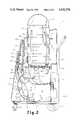
- FIG. 2is a side view in vertical cross section of the powerbase unit of the apparatus.
- FIG. 3is a rear detail cross section of the powerbase unit of the apparatus taken along line 3--3 of FIG. 2.
- FIG. 4is a front elevational view of the instrument panel of the powerhead unit of the apparatus.
- FIG. 5is a side view in vertical cross section of the powerhead unit of the apparatus.
- FIG. 6is a bottom plan view of the housing of the powerhead unit of the apparatus.
- FIG. 7is a detail view of a portion of the suction head member of the apparatus.
- FIG. 8is a schematic illustration of the nozzle selection feature of the apparatus.
- Truck mounted equipmentwas soon found to have substantial deficiencies. This equipment tended to generate excessive heat which could set the nap or damage fiber.
- the large truck-mounted unitsare expensive and raise prices to the consumer considerably.
- the location of the power plant in the truckhas required very long lengths of hose to reach throughout areas being serviced. Consequently, manufacturers have taken a step backward to the old hot water extractors, rotary brush machines, to to a new generation of high-powered portable machines.
- a dry vacuum systemis required with adequate lift and mechanical agitation of the carpet.
- a spray systemis required for introducing detergent for cleaning or clear water for rinsing at high pressure and low volume. The system must deliver liquid in front of a trailing extractor wand during rinsing.
- the spray system for introducing water borne dye pigmentmust operate at low pressure and high volume and must deliver liquid evenly and as close to the walls as the housing construction permits. Brushing action must be rotary in a direction raising the fibers rather than laying them flat to permit liquid penetration without overwetting.
- a wet vacuum systemis needed which can be used selectively and periodically. Provision must be made for shutting down the equipment and warning the operator on occurrence of maximum horsepower delivered to the brushes, maximum lift at the vacuum, and maximum pressure at the pump.
- FIGS. 1-4there is shown a preferred embodiment of a combination carpet vacuum, cleaning, and dyeing apparatus 10 comprising a powerbase unit 11 and a powerhead unit 12.
- the powerbase unit 11houses the vacuum and water pressure systems, the electrical circuitry, and mixing devices to supply the powerhead unit 12 with various solutions of water and other chemicals.
- the powerhead unit 12carries the motor and transmission to drive the brushes, sprayer manifolds for carpet cleaning and dyeing, a vacuum head, counterrotating brushes, electronic circuitry, and operator controls to provide the operator with manifold selection, remote vacuum control, and motor control.
- the powerbase unit 11comprises a generally box shaped lower component housing 13 having rear, left side, front, and right side walls, 14, 15, 16, and 17, respectively.
- An electronics mounting plate 18forms the bottom of the housing 13 and carries some of the electronic components of the circuitry.
- the housing 13is mounted on a tubular frame cart 59 having a front pair of casters 60 and a rear pair of wheels 61.
- a molded extension at the top of the front wall 16is contoured to form an instrument panel 19 thereon.
- the top 20 of housing 13is enclosed and provided with a rectangular recessed portion 21 to receive a generally rectangular detergent tank 22.
- Detergent tank 22has an upwardly extended elbow opening 23 at its top and two small depending tubes 24 and 25 at its bottom which protrude from the recessed portion 21.
- a flexible hose 26connects the elbow 23 to a filler neck fitting 27 at the top of the instrument panel 19.
- a length of tubing 28connects one depending tube 25 to a 3/4" ball valve 29 attached to the rear wall 14 of the housing 13 for dumping the system.
- a second length of tubing 30connects the other depending tube 24 to a vacuum break tube 31 connected at instrument panel 19 to a flow meter 32 calibrated in ounces per gallon.
- Vacuum break tube 31extends above the highest liquid level to prevent unwanted water and chemical from entering the system.
- Another length of tubing 33runs from the flow meter 32 to a tee fitting 34 which is in turn connected by another length of tubing 35 to the inlet side 135 of a pump 36 supported on plate 18.
- Another length of tubing 37connects the discharge side 137 of the pump 36 to a quick disconnect coupling 38 in the instrument panel 19.
- a generally rectangular clear water tank 39having a circular opening 40 in its top and a recessed bottom, slip fits onto the top 20 of the housing 13 at the rear of instrument panel 19.
- Clear water tank 39is secured to the top 20 of the housing 13 by conventional bulkhead fittings.
- a length of tubing 41connects water tank 39 to a 3/4" ball valve 42 attached to the rear wall 14 of the housing 13 for dumping the system.
- tubing 43runs from a second bulkhead fitting which has an internal strainer (not shown) at the bottom of the clear water tank 39 to a second tee fitting 44 connected in line with the first tee fitting 34.
- a small 1/8" bypass tube 45extends from the stem of tee fitting 44 to the discharge side of pump 36.
- a closed bottom hollow cylindrical recovery tank 46extends through the circular opening 40 of the water tank 39 and rests on the bottom of the clear water tank 39. Recovery tank 46 is secured to housing 13 by bulkhead fittings. A length of 1" tubing 47 connects the recovery tank 46 to a 1" ball valve 48 attached to the rear wall 14 of the housing 13 for dumping the system. A clear acrylic dome 49 sealably fits on the top of the recovery tank 46 to allow observation of the extraction process.
- a vacuum motor 50attached to the underside of the top 20 of the housing 13 and has suction tube 51 extending upwardly outside the recovery tank 46 and opening into tank 46 near its top.
- An air inlet tube 52is attached to the bottom of the recovery tank 46 by bulkhead fittings and extends upwardly therein.
- a vacuum hose 53connects inlet tube 52 to a hose fitting 54 in the instrument panel 19.
- a liquid level sensor 55 mounted on the clear water tank 39will shut down the pump 36 and light a warning light 56 (FIG. 4) on the instrument panel 19 to protect the unit from running dry and alert the operator that the water supply is gone.
- Another liquid level sensor 57 mounted on recovery tank 46will shut down the vacuum system and warn the operator with a light 58 of a full recovery tank to prevent liquid from being drawn into the vacuum motor 50.
- powerhead unit 12comprises a generally rectangular housing 62 having rear, left side, front, and right side walls, 63, 64, 65, and 66 respectively.
- the top surface 67 of the housing 62has an opening 68.
- a bifurcated tubular handle 69is pivotally connected to the housing 62 and a telescoping and lockable handle lock tube 70 is connected therebetween to provide handle height adjustment for operator convenience.
- a nozzle selection switch 71, on-off brush motor switch 72, and low voltage vacuum motor switch 73are installed in a switch cover 74 near the handlebars 75. Vacuum motor switch 73 trips a relay in the powerbase unit 11 to actuate vacuum motor 50.
- Motor cover 76attaches to the top 67 of housing 62 to cover the power unit for the brush system.
- a pair of front wheels 77 and rear wheels 78are rotatably attached to a pair of front wheel cam brackets 79 and a pair of rear wheel cam brackets 80 which are pivotally attached to the left and right side walls 64 and 66.
- a pair of wheel adjustment rods 81pivotally connect each front and rear cam bracket 79 and 80.
- a transverse cross bar 82connects the two rear cam brackets 80 and a spring biased wheel adjustment lever 83 is pivotally attached thereto.
- Lever 83extends through vertical slot 84 in the rear wall 63 which has a series of vertically spaced arcuate openings 85 along one side.
- the lever and slot mechanismprovides height adjustment of the wheels 77 and 78 relative to the housing 62. Vertical height adjustment is necessary to accomodate different heights of carpet pile.
- a larger pair of wheels 86are rotatably mounted on an axle extending between the left and right side walls 64 and 66 near the rear of the housing 62 for transporting the powerhead unit 12 when not in use.
- the power unit for the brush systemcomprises a vertically disposed 24 volt D.C. motor 87 (FIG. 5) and a small transmission 88 attached to the top surface 67 of the housing 62.
- Transmission 88contains a vertical worm gear which drives two lateral counterrotating worm gears each having sheaves 89 at their extended end.
- the brushes for the powerhead unitcomprise elongated stainless steel front and rear brush tubes 90 and 91 respectively, having circumferentially disposed spirally wound outwardly extending bristles 92.
- a sheave 93 smaller in diameter than the extended ends of the bristles 92is disposed on each brush tube in alignment with the sheaves 89 on the transmission 88 and a timing belt 94 connected therebetween drives the brushes in counter rotation.
- the brush tubes 90 and 91are journaled on axles 95 extending between the left and right side walls 64 and 66.
- the counterrotational brushing actioncarries each fiber in complete rotation (left to right and front to rear), to provide maximum fiber grooming, dirt removal, and penetration of liquids without overwetting.
- Low voltage D.C.is supplied by a dual wound enclosed transformer 96 (FIG. 2) and rectified by integrated full wave bridge circuits.
- the low voltage 24 volt D.C. motoris safer than the typical 115 volts delivered to a conventional machine and it effectively uses only 3 amps on the primary side of the transformer but delivers 20 amps and the resulting high R.P.M. associated with D.C. motors to the transmission.
- the R.P.M.sare reduced through the transmission yielding the same torque that would require 13 amps in a conventional A.C. motor. Individually fused circuits provide additional safety.
- a floating suction member or vacuum head 97is located neat the front wall 65 of the housing 62.
- the vacuum head 97comprises a generally hollow T-shaped tubular member having an angularly and upwardly extending hollow stem portion 98 and its two opposed extended ends 99 are closed.
- a slot 100extends longitudinally between the closed ends 99 on the underside of the vacuum head 97.
- Pins 101extend outwardly from the closed ends 99 and slide vertically in slots 102 provided in brackets 103 attached to left and right side wall 64 and 66 of the housing 62.
- Compression springs 104 mounted on vertically extending pins 105 atop each extended end of the vacuum head 97are biased between the top of the housing 67 and the head 97 to urge it downward onto the carpet surface.
- a flexible hose 106connects the hollow stem 98 of the vacuum head 97 to the lower end of a clear plastic vacuum tube 107 attached to the handle 69.
- a longer flexible hose 108connects the upper end of the clear vacuum tube 107 to the hose fitting 54 on the instrument panel 19 of the powerbase unit 11. Clear plastic vacuum tube 107 allows the operator to observe the extraction process.
- the floating vacuum head 97carries two sets of spray nozzles 109 and 110 attached to a flat horizontal mounting flange 111 at the top thereof.
- Flange 111extends forward and rearward relative to the slot 100 and its height is such that the tip of the nozzles is preferably 1.8" above the slotted bottom of the vacuum head 97.
- the front set of nozzles 109are used for the dyeing operation, and the rear set of nozzles 110 are used in the cleaning operation. Forward displacement of the front nozzles 109 is adequate to provide application of solution as close to room walls as possible, and rearward displacement of the rear nozzles 111 is based upon the normal cleaning action of a rearward motion which applies solution just prior to extraction by the vacuum head 97.
- Nozzle selectionis accomplished with the switch 71 which operates either of two relays or electromagnetic valves 112 and 113 (FIG. 8).
- One valve 112controls liquid supply to the front nozzles 109 through tubing 114
- the other valve 113controls liquid flow to the rear nozzles 110 through tubing 115.
- the two sections of tubing 114 and 115are joined by a tee fitting and another section of tubing 116 extends therefrom upwardly along the handle 69 and is joined by another tee fitting to two opposed quick disconnect couplings 117 and 118 extending outwardly from switch cover 75.
- a small relatively long pressure hose 119connects one quick disconnect coupling to the quick disconnect coupling 38 at the instrument panel 19 to provide the vacuum head 97 with various solutions of water and other chemicals.
- the powerbase unit 11 of the apparatusis plugged into a 110 volt A.C. outlet and the switch turned on to start the vacuum motor 50 causing a partial vacuum within the recovery tank 46.
- Airis drawn into slot 100 at the bottom of the floating vacuum head 97 in the powerhead unit 12 and travels through the clear vacuum tube 108 and connecting hoses to enter the recovery tank 46 on the powerbase unit. The degree of extraction may be observed through the clear vacuum tube and the clear dome 49 on the tank and the carpet may be dry vacuumed in the normal manner.
- the clear water tank 39 and the detergent tank 22are filled.
- the vacuum motor 50is once again turned on and the pump motor switch is turned to pressurize the system.
- the brush motor 87is turned on and the nozzle selection switch 71 is turned to select the rear nozzles 110.
- the normal cleaning actionis a rearward motion and the application of the detergent solution just prior to extraction by the vacuum head.
- the dyeing operationfollows the same procedure as the cleaning operation except that the dye solution is put into the solution tank and the front nozzles 109 are put into operation.
- the counterrotational brushing actioncarries each fiber in complete rotation (left to right and front to rear), to provide maximum fiber grooming, dirt removal, and penetration of liquids without overwetting.
Landscapes
- Treatment Of Fiber Materials (AREA)
Abstract
Description
Claims (29)
Priority Applications (1)
| Application Number | Priority Date | Filing Date | Title |
|---|---|---|---|
| US06/577,070US4542556A (en) | 1984-02-06 | 1984-02-06 | Carpet vacuum, cleaning, and dyeing apparatus |
Applications Claiming Priority (1)
| Application Number | Priority Date | Filing Date | Title |
|---|---|---|---|
| US06/577,070US4542556A (en) | 1984-02-06 | 1984-02-06 | Carpet vacuum, cleaning, and dyeing apparatus |
Publications (1)
| Publication Number | Publication Date |
|---|---|
| US4542556Atrue US4542556A (en) | 1985-09-24 |
Family
ID=24307156
Family Applications (1)
| Application Number | Title | Priority Date | Filing Date |
|---|---|---|---|
| US06/577,070Expired - LifetimeUS4542556A (en) | 1984-02-06 | 1984-02-06 | Carpet vacuum, cleaning, and dyeing apparatus |
Country Status (1)
| Country | Link |
|---|---|
| US (1) | US4542556A (en) |
Cited By (43)
| Publication number | Priority date | Publication date | Assignee | Title |
|---|---|---|---|---|
| US4608062A (en)* | 1985-03-13 | 1986-08-26 | Container Products Corporation | Contaminated air/water recovery apparatus |
| US4723337A (en)* | 1986-12-09 | 1988-02-09 | Shumpert & Ellison, Inc. | High pressure carpet or rug cleaning apparatus |
| USD297060S (en) | 1985-07-17 | 1988-08-02 | Rug Doctor, Inc. | Vacuum cleaning machine |
| USD297061S (en) | 1985-07-17 | 1988-08-02 | Rug Doctor, Inc. | Vacuum cleaning machine |
| US4809396A (en)* | 1987-06-29 | 1989-03-07 | Houser Franklin C | Combination vacuum and solution-dispensing apparatus |
| US4951346A (en)* | 1987-06-02 | 1990-08-28 | Carl Salmon | Cleaning attachment |
| US4956891A (en)* | 1990-02-21 | 1990-09-18 | Castex Industries, Inc. | Floor cleaner |
| USD312336S (en) | 1988-06-17 | 1990-11-20 | Greenlee Textron Inc. | Power fishtape blower/vacuum unit |
| DE9003440U1 (en)* | 1990-03-23 | 1991-07-25 | Siemens AG, 1000 Berlin und 8000 München | Additional device that can be connected to a vacuum cleaner |
| GB2243992A (en)* | 1990-05-04 | 1991-11-20 | Geraint Lloyd Owens | Solvent extraction carpet-cleaning machine |
| US5237719A (en)* | 1991-10-17 | 1993-08-24 | Donald J. Dwyer, Sr. | Cleaning apparatus |
| USD349791S (en) | 1988-05-19 | 1994-08-16 | Shop-Vac Corporation | Wheeled type suction producing unit for vacuum cleaner |
| US5465455A (en)* | 1994-05-27 | 1995-11-14 | Allen; Harold | Overload controlled wet and dry vacuum apparatus |
| US5483726A (en)* | 1993-01-04 | 1996-01-16 | Bissell Inc. | Combination vacuum cleaner and water extractor power foot |
| US5542147A (en)* | 1995-05-02 | 1996-08-06 | Bissell Inc. | Spray suction and agitator control and deep cleaning machine |
| WO1999026522A1 (en)* | 1997-11-26 | 1999-06-03 | Simac-Vetrella Spa | Steam cleaning apparatus |
| US5951780A (en)* | 1993-07-20 | 1999-09-14 | Pettigrew; Rodney Mackenzie | Surface treatment method and apparatus including brush means and impact means mounted on a single shaft |
| US6230362B1 (en) | 1997-07-09 | 2001-05-15 | Bissell Homecare, Inc. | Upright extraction cleaning machine |
| US6533833B1 (en)* | 2001-05-24 | 2003-03-18 | Mark Schmitz | Method of apparatus for air and liquid vacuuming |
| US20040055106A1 (en)* | 2002-09-20 | 2004-03-25 | Yacobi Michael S. | Dual agitator drive system with worm gear |
| US20040078924A1 (en)* | 2001-04-06 | 2004-04-29 | Roney Jeffrey T. | Agitator drive system with bare floor shifter |
| US20050160555A1 (en)* | 2004-01-27 | 2005-07-28 | Panasonic Corporation Of North America | Vacuum cleaner with twin independently driven agitators |
| US20050172447A1 (en)* | 2004-02-05 | 2005-08-11 | Panasonic Corporation Of North America | Floor cleaning apparatus with twin agitators having different diameters |
| US20050207825A1 (en)* | 2004-03-22 | 2005-09-22 | Martin Michael B | Weighted scrub brush |
| US20060112513A1 (en)* | 2004-11-29 | 2006-06-01 | Tetteh Albert E | Indoor/outdoor cleaning system |
| US20070113528A1 (en)* | 2005-10-18 | 2007-05-24 | Knuth Steven L | Vacuum bag mounting and viewing features |
| US20100150640A1 (en)* | 2004-11-29 | 2010-06-17 | Albert Tetteh | Indoor/outdoor cleaning system |
| US20130061422A1 (en)* | 2011-08-31 | 2013-03-14 | Dri-Eaz Products, Inc | Multi-operational mode fluid extractors and associated methods of use and manufacture |
| US8635740B2 (en) | 2010-09-01 | 2014-01-28 | Techtronic Floor Care Technology Limited | Flow control of an extractor cleaning machine |
| WO2015073914A1 (en)* | 2013-11-15 | 2015-05-21 | Dri-Eaz Products, Inc. | Power/water supply and reclamation tank for cleaning devices, and associated systems and methods |
| US9144359B2 (en) | 2012-11-27 | 2015-09-29 | Albert W. Gebhard | Carpet cleaning device |
| EP2832277A3 (en)* | 2013-08-02 | 2015-10-21 | i-mop GmbH | Hand-guided soil working device |
| US9179812B2 (en) | 2012-11-19 | 2015-11-10 | Sapphire Scientific Inc. | Hard surface cleaners having cleaning heads with rotational assist, and associated systems, apparatuses and methods |
| US9351622B2 (en) | 2012-09-04 | 2016-05-31 | Sapphire Scientific Inc. | Fluid extracting device with shaped head and associated systems and methods of use and manufacture |
| US9560949B2 (en) | 2007-12-03 | 2017-02-07 | Sapphire Scientific, Inc. | Air induction hard surface cleaning tools with an internal baffle |
| EP3113663A4 (en)* | 2014-02-28 | 2017-12-13 | Rug Doctor, LLC | Liquid extraction cleaning device and method |
| WO2018127680A1 (en)* | 2017-01-09 | 2018-07-12 | Dyson Technology Limited | Cleaner head for a vacuum cleaner |
| US10060641B2 (en) | 2015-02-25 | 2018-08-28 | Dri-Eaz Products, Inc. | Systems and methods for drying roofs |
| US10264939B2 (en) | 2015-08-17 | 2019-04-23 | Skagit Northwest Holdings, Inc. | Rotary surface cleaning tool |
| US10278559B1 (en)* | 2014-10-06 | 2019-05-07 | Foaming Floors LLC | Foaming floor cleaner apparatus and system |
| EP3393323A4 (en)* | 2015-12-22 | 2019-08-14 | Run The Race Pty Ltd | FASTENING OF ENHANCED SUCTION HEAD AND VACUUM CLEANER |
| US10584497B2 (en) | 2014-12-05 | 2020-03-10 | Dri-Eaz Products, Inc. | Roof cleaning processes and associated systems |
| EP3721777A1 (en)* | 2017-07-26 | 2020-10-14 | Hawig Maschinenfabrik Gesellschaft mit beschränkter Haftung | Surfaces machining apparatus |
Citations (11)
| Publication number | Priority date | Publication date | Assignee | Title |
|---|---|---|---|---|
| US3619849A (en)* | 1970-02-24 | 1971-11-16 | Judson O Jones | Wet pick-up portable cleaning apparatus |
| US3654662A (en)* | 1970-06-15 | 1972-04-11 | Cardic Machine Products Inc | Rug cleaning machine |
| US3818537A (en)* | 1973-01-29 | 1974-06-25 | J Evans | Heated liquid vacuum generator for use with a two chamber cleaning nozzle |
| US3919729A (en)* | 1974-08-01 | 1975-11-18 | Servicemaster Ind | Method for cleaning carpets |
| US3942215A (en)* | 1972-11-13 | 1976-03-09 | Olds James O | Floor maintenance machine |
| US4139922A (en)* | 1977-08-19 | 1979-02-20 | Chester Fitch | Carpet cleaning device |
| US4167799A (en)* | 1978-05-10 | 1979-09-18 | Webb Charles F | Carpet cleaning machine |
| US4207649A (en)* | 1976-03-09 | 1980-06-17 | Bates Jack A | Carpet cleaning machine |
| US4218900A (en)* | 1979-08-06 | 1980-08-26 | Lew Caplan | Carpet cleaning and dyeing apparatus |
| US4307484A (en)* | 1979-09-28 | 1981-12-29 | U.S. Floor Systems, Inc. | Cleaning apparatus and method |
| US4360946A (en)* | 1980-04-30 | 1982-11-30 | Duraclean International | Apparatus for cleaning floors and floor coverings |
- 1984
- 1984-02-06USUS06/577,070patent/US4542556A/ennot_activeExpired - Lifetime
Patent Citations (11)
| Publication number | Priority date | Publication date | Assignee | Title |
|---|---|---|---|---|
| US3619849A (en)* | 1970-02-24 | 1971-11-16 | Judson O Jones | Wet pick-up portable cleaning apparatus |
| US3654662A (en)* | 1970-06-15 | 1972-04-11 | Cardic Machine Products Inc | Rug cleaning machine |
| US3942215A (en)* | 1972-11-13 | 1976-03-09 | Olds James O | Floor maintenance machine |
| US3818537A (en)* | 1973-01-29 | 1974-06-25 | J Evans | Heated liquid vacuum generator for use with a two chamber cleaning nozzle |
| US3919729A (en)* | 1974-08-01 | 1975-11-18 | Servicemaster Ind | Method for cleaning carpets |
| US4207649A (en)* | 1976-03-09 | 1980-06-17 | Bates Jack A | Carpet cleaning machine |
| US4139922A (en)* | 1977-08-19 | 1979-02-20 | Chester Fitch | Carpet cleaning device |
| US4167799A (en)* | 1978-05-10 | 1979-09-18 | Webb Charles F | Carpet cleaning machine |
| US4218900A (en)* | 1979-08-06 | 1980-08-26 | Lew Caplan | Carpet cleaning and dyeing apparatus |
| US4307484A (en)* | 1979-09-28 | 1981-12-29 | U.S. Floor Systems, Inc. | Cleaning apparatus and method |
| US4360946A (en)* | 1980-04-30 | 1982-11-30 | Duraclean International | Apparatus for cleaning floors and floor coverings |
Cited By (55)
| Publication number | Priority date | Publication date | Assignee | Title |
|---|---|---|---|---|
| US4608062A (en)* | 1985-03-13 | 1986-08-26 | Container Products Corporation | Contaminated air/water recovery apparatus |
| USD297060S (en) | 1985-07-17 | 1988-08-02 | Rug Doctor, Inc. | Vacuum cleaning machine |
| USD297061S (en) | 1985-07-17 | 1988-08-02 | Rug Doctor, Inc. | Vacuum cleaning machine |
| US4723337A (en)* | 1986-12-09 | 1988-02-09 | Shumpert & Ellison, Inc. | High pressure carpet or rug cleaning apparatus |
| US4951346A (en)* | 1987-06-02 | 1990-08-28 | Carl Salmon | Cleaning attachment |
| US4809396A (en)* | 1987-06-29 | 1989-03-07 | Houser Franklin C | Combination vacuum and solution-dispensing apparatus |
| USD349791S (en) | 1988-05-19 | 1994-08-16 | Shop-Vac Corporation | Wheeled type suction producing unit for vacuum cleaner |
| USD312336S (en) | 1988-06-17 | 1990-11-20 | Greenlee Textron Inc. | Power fishtape blower/vacuum unit |
| US4956891A (en)* | 1990-02-21 | 1990-09-18 | Castex Industries, Inc. | Floor cleaner |
| DE9003440U1 (en)* | 1990-03-23 | 1991-07-25 | Siemens AG, 1000 Berlin und 8000 München | Additional device that can be connected to a vacuum cleaner |
| GB2243992A (en)* | 1990-05-04 | 1991-11-20 | Geraint Lloyd Owens | Solvent extraction carpet-cleaning machine |
| US5237719A (en)* | 1991-10-17 | 1993-08-24 | Donald J. Dwyer, Sr. | Cleaning apparatus |
| US5483726A (en)* | 1993-01-04 | 1996-01-16 | Bissell Inc. | Combination vacuum cleaner and water extractor power foot |
| US5951780A (en)* | 1993-07-20 | 1999-09-14 | Pettigrew; Rodney Mackenzie | Surface treatment method and apparatus including brush means and impact means mounted on a single shaft |
| US5465455A (en)* | 1994-05-27 | 1995-11-14 | Allen; Harold | Overload controlled wet and dry vacuum apparatus |
| US5542147A (en)* | 1995-05-02 | 1996-08-06 | Bissell Inc. | Spray suction and agitator control and deep cleaning machine |
| US6230362B1 (en) | 1997-07-09 | 2001-05-15 | Bissell Homecare, Inc. | Upright extraction cleaning machine |
| WO1999026522A1 (en)* | 1997-11-26 | 1999-06-03 | Simac-Vetrella Spa | Steam cleaning apparatus |
| US20040078924A1 (en)* | 2001-04-06 | 2004-04-29 | Roney Jeffrey T. | Agitator drive system with bare floor shifter |
| US6915544B2 (en) | 2001-04-06 | 2005-07-12 | Panasonic Corporation Of North America | Agitator drive system with bare floor shifter |
| US6533833B1 (en)* | 2001-05-24 | 2003-03-18 | Mark Schmitz | Method of apparatus for air and liquid vacuuming |
| US20040237486A1 (en)* | 2001-05-24 | 2004-12-02 | Mark Schmitz | Method of and apparatus for air and liquid vacuuming |
| US20040055106A1 (en)* | 2002-09-20 | 2004-03-25 | Yacobi Michael S. | Dual agitator drive system with worm gear |
| US6918155B2 (en) | 2002-09-20 | 2005-07-19 | Panasonic Corporation Of North America | Dual agitator drive system with worm gear |
| US20050160555A1 (en)* | 2004-01-27 | 2005-07-28 | Panasonic Corporation Of North America | Vacuum cleaner with twin independently driven agitators |
| US20050172447A1 (en)* | 2004-02-05 | 2005-08-11 | Panasonic Corporation Of North America | Floor cleaning apparatus with twin agitators having different diameters |
| US20050207825A1 (en)* | 2004-03-22 | 2005-09-22 | Martin Michael B | Weighted scrub brush |
| US7481594B2 (en)* | 2004-03-22 | 2009-01-27 | Mb Manufacturing | Weighted scrub brush |
| US8640299B2 (en)* | 2004-11-29 | 2014-02-04 | Albert E. Tetteh | Indoor/outdoor cleaning system |
| US20100150640A1 (en)* | 2004-11-29 | 2010-06-17 | Albert Tetteh | Indoor/outdoor cleaning system |
| US20060112513A1 (en)* | 2004-11-29 | 2006-06-01 | Tetteh Albert E | Indoor/outdoor cleaning system |
| US20070113528A1 (en)* | 2005-10-18 | 2007-05-24 | Knuth Steven L | Vacuum bag mounting and viewing features |
| US7662200B2 (en) | 2005-10-18 | 2010-02-16 | Electrolux Home Care Products, Inc. | Vacuum bag mounting and viewing features |
| US9560949B2 (en) | 2007-12-03 | 2017-02-07 | Sapphire Scientific, Inc. | Air induction hard surface cleaning tools with an internal baffle |
| US8635740B2 (en) | 2010-09-01 | 2014-01-28 | Techtronic Floor Care Technology Limited | Flow control of an extractor cleaning machine |
| US20130061422A1 (en)* | 2011-08-31 | 2013-03-14 | Dri-Eaz Products, Inc | Multi-operational mode fluid extractors and associated methods of use and manufacture |
| US9351622B2 (en) | 2012-09-04 | 2016-05-31 | Sapphire Scientific Inc. | Fluid extracting device with shaped head and associated systems and methods of use and manufacture |
| US9179812B2 (en) | 2012-11-19 | 2015-11-10 | Sapphire Scientific Inc. | Hard surface cleaners having cleaning heads with rotational assist, and associated systems, apparatuses and methods |
| US9144359B2 (en) | 2012-11-27 | 2015-09-29 | Albert W. Gebhard | Carpet cleaning device |
| US9826874B2 (en) | 2013-08-02 | 2017-11-28 | I-Mop Gmbh | Hand-guided floor treatment device |
| EP3031378A1 (en)* | 2013-08-02 | 2016-06-15 | i-mop GmbH | Hand-guided soil working device |
| EP2832277A3 (en)* | 2013-08-02 | 2015-10-21 | i-mop GmbH | Hand-guided soil working device |
| US10022031B2 (en) | 2013-11-15 | 2018-07-17 | Dri-Eaz Products, Inc. | Power/water supply and reclamation tank for cleaning devices, and associated systems and methods |
| WO2015073914A1 (en)* | 2013-11-15 | 2015-05-21 | Dri-Eaz Products, Inc. | Power/water supply and reclamation tank for cleaning devices, and associated systems and methods |
| EP3113663A4 (en)* | 2014-02-28 | 2017-12-13 | Rug Doctor, LLC | Liquid extraction cleaning device and method |
| US10278559B1 (en)* | 2014-10-06 | 2019-05-07 | Foaming Floors LLC | Foaming floor cleaner apparatus and system |
| US10584497B2 (en) | 2014-12-05 | 2020-03-10 | Dri-Eaz Products, Inc. | Roof cleaning processes and associated systems |
| US10753628B2 (en) | 2015-02-25 | 2020-08-25 | Legend Brands, Inc. | Systems and methods for drying roofs |
| US11686482B2 (en) | 2015-02-25 | 2023-06-27 | Legend Brands, Inc. | Systems and methods for drying roofs |
| US10060641B2 (en) | 2015-02-25 | 2018-08-28 | Dri-Eaz Products, Inc. | Systems and methods for drying roofs |
| US10264939B2 (en) | 2015-08-17 | 2019-04-23 | Skagit Northwest Holdings, Inc. | Rotary surface cleaning tool |
| EP3393323A4 (en)* | 2015-12-22 | 2019-08-14 | Run The Race Pty Ltd | FASTENING OF ENHANCED SUCTION HEAD AND VACUUM CLEANER |
| AU2016374644B2 (en)* | 2015-12-22 | 2021-07-29 | Run The Race Pty Ltd | Improved vacuum head attachment and vacuum cleaner |
| WO2018127680A1 (en)* | 2017-01-09 | 2018-07-12 | Dyson Technology Limited | Cleaner head for a vacuum cleaner |
| EP3721777A1 (en)* | 2017-07-26 | 2020-10-14 | Hawig Maschinenfabrik Gesellschaft mit beschränkter Haftung | Surfaces machining apparatus |
Similar Documents
| Publication | Publication Date | Title |
|---|---|---|
| US4542556A (en) | Carpet vacuum, cleaning, and dyeing apparatus | |
| US4146944A (en) | Carpet cleaning machine | |
| CN211066435U (en) | Surface cleaning apparatus | |
| US3614797A (en) | Method for cleaning and partially drying carpets | |
| US4196492A (en) | Automatic carpet cleaning machine | |
| US4210978A (en) | Automatic carpet cleaning machine | |
| US4329756A (en) | Hot water extraction carpet and floor cleaning machine | |
| EP1753335B1 (en) | Secondary introduction of fluid into vacuum system | |
| US7967914B2 (en) | Method and apparatus for cleaning fabrics, floor coverings, and bare floor surfaces utilizing a soil transfer medium | |
| US4000536A (en) | Floor cleaning machine with foam dispensing system | |
| US4353145A (en) | Rug cleaning apparatus | |
| US6735812B2 (en) | Dual mode carpet cleaning apparatus utilizing an extraction device and a soil transfer cleaning medium | |
| US4114229A (en) | Surface cleaning apparatus | |
| US3964925A (en) | Apparatus for treating floor coverings | |
| US3755850A (en) | Steam cleaning machine | |
| CN113243850A (en) | Communication method for base station and surface cleaning equipment and storage medium | |
| US20060236494A1 (en) | Hard and soft floor surface cleaner | |
| US4168563A (en) | System for carrying out the in situ cleaning of carpet | |
| US6766556B2 (en) | Apparatus for cleaning surfaces with automatic water supply and drain | |
| US3619849A (en) | Wet pick-up portable cleaning apparatus | |
| CN115379786A (en) | Cleaning solution application for surface maintenance machines | |
| GB2399738A (en) | Constant head device for a cleaning machine | |
| US4151627A (en) | Cleaning and coloring apparatus | |
| GB2352166A (en) | Wet cleaning apparatus and method, in particular for road and like surfaces, using rinsing and suction | |
| US20050055793A1 (en) | Cleaning apparatus |
Legal Events
| Date | Code | Title | Description |
|---|---|---|---|
| AS | Assignment | Owner name:HIGHTEC MANUFACTURING CORPORATION, A CORP OF TX Free format text:ASSIGNMENT OF ASSIGNORS INTEREST.;ASSIGNOR:HEPPLE, JEFFRY S.;REEL/FRAME:004225/0791 Effective date:19840121 | |
| REMI | Maintenance fee reminder mailed | ||
| REIN | Reinstatement after maintenance fee payment confirmed | ||
| FP | Lapsed due to failure to pay maintenance fee | Effective date:19890924 | |
| FEPP | Fee payment procedure | Free format text:PETITION RELATED TO MAINTENANCE FEES FILED (ORIGINAL EVENT CODE: PMFP); ENTITY STATUS OF PATENT OWNER: SMALL ENTITY | |
| FEPP | Fee payment procedure | Free format text:PETITION RELATED TO MAINTENANCE FEES DENIED/DISMISSED (ORIGINAL EVENT CODE: PMFD); ENTITY STATUS OF PATENT OWNER: SMALL ENTITY | |
| FEPP | Fee payment procedure | Free format text:PETITION RELATED TO MAINTENANCE FEES FILED (ORIGINAL EVENT CODE: PMFP); ENTITY STATUS OF PATENT OWNER: SMALL ENTITY | |
| FEPP | Fee payment procedure | Free format text:PETITION RELATED TO MAINTENANCE FEES GRANTED (ORIGINAL EVENT CODE: PMFG); ENTITY STATUS OF PATENT OWNER: SMALL ENTITY | |
| FPAY | Fee payment | Year of fee payment:4 | |
| SULP | Surcharge for late payment | ||
| STCF | Information on status: patent grant | Free format text:PATENTED CASE | |
| FPAY | Fee payment | Year of fee payment:8 | |
| DP | Notification of acceptance of delayed payment of maintenance fee | ||
| FEPP | Fee payment procedure | Free format text:PAYOR NUMBER ASSIGNED (ORIGINAL EVENT CODE: ASPN); ENTITY STATUS OF PATENT OWNER: SMALL ENTITY |