US4540099A - Tamper indicating package - Google Patents
Tamper indicating packageDownload PDFInfo
- Publication number
- US4540099A US4540099AUS06/607,082US60708284AUS4540099AUS 4540099 AUS4540099 AUS 4540099AUS 60708284 AUS60708284 AUS 60708284AUS 4540099 AUS4540099 AUS 4540099A
- Authority
- US
- United States
- Prior art keywords
- closure
- container
- band
- tamper indicating
- legs
- Prior art date
- Legal status (The legal status is an assumption and is not a legal conclusion. Google has not performed a legal analysis and makes no representation as to the accuracy of the status listed.)
- Expired - Lifetime
Links
- 239000000463materialSubstances0.000claimsabstractdescription10
- 230000002401inhibitory effectEffects0.000claims4
- 239000011324beadSubstances0.000description8
- 229920003023plasticPolymers0.000description6
- 239000004033plasticSubstances0.000description6
- 239000011521glassSubstances0.000description2
- 239000004743PolypropyleneSubstances0.000description1
- 229920001903high density polyethylenePolymers0.000description1
- 229920001684low density polyethylenePolymers0.000description1
- 238000004519manufacturing processMethods0.000description1
- 239000002184metalSubstances0.000description1
- 238000000465mouldingMethods0.000description1
- -1polypropylenePolymers0.000description1
- 229920001155polypropylenePolymers0.000description1
- 239000000126substanceSubstances0.000description1
- 230000000007visual effectEffects0.000description1
Images

Classifications
- B—PERFORMING OPERATIONS; TRANSPORTING
- B65—CONVEYING; PACKING; STORING; HANDLING THIN OR FILAMENTARY MATERIAL
- B65D—CONTAINERS FOR STORAGE OR TRANSPORT OF ARTICLES OR MATERIALS, e.g. BAGS, BARRELS, BOTTLES, BOXES, CANS, CARTONS, CRATES, DRUMS, JARS, TANKS, HOPPERS, FORWARDING CONTAINERS; ACCESSORIES, CLOSURES, OR FITTINGS THEREFOR; PACKAGING ELEMENTS; PACKAGES
- B65D55/00—Accessories for container closures not otherwise provided for
- B65D55/02—Locking devices; Means for discouraging or indicating unauthorised opening or removal of closure
- B65D55/06—Deformable or tearable wires, strings or strips; Use of seals
- B65D55/08—Annular elements encircling container necks
- B65D55/0863—Plastic snap-on cap-like collars having frangible parts
Definitions
- the internal diameter of the beadmay be equal to or slightly less than the diameter of the flange 14 such that the heat will shrink the band 24 bringing the bead below the flange 14.
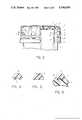
- the axial portions 23preferably are formed with axial ribs 27 (FIG. 4) which interengage the axial ribs 28 on the closure (FIG. 6) to prevent relative rotation between the tamper indicating device and the closure.
Landscapes
- Engineering & Computer Science (AREA)
- Mechanical Engineering (AREA)
- Closures For Containers (AREA)
Abstract
Description
Claims (10)
Priority Applications (1)
| Application Number | Priority Date | Filing Date | Title |
|---|---|---|---|
| US06/607,082US4540099A (en) | 1984-05-04 | 1984-05-04 | Tamper indicating package |
Applications Claiming Priority (1)
| Application Number | Priority Date | Filing Date | Title |
|---|---|---|---|
| US06/607,082US4540099A (en) | 1984-05-04 | 1984-05-04 | Tamper indicating package |
Publications (1)
| Publication Number | Publication Date |
|---|---|
| US4540099Atrue US4540099A (en) | 1985-09-10 |
Family
ID=24430734
Family Applications (1)
| Application Number | Title | Priority Date | Filing Date |
|---|---|---|---|
| US06/607,082Expired - LifetimeUS4540099A (en) | 1984-05-04 | 1984-05-04 | Tamper indicating package |
Country Status (1)
| Country | Link |
|---|---|
| US (1) | US4540099A (en) |
Cited By (12)
| Publication number | Priority date | Publication date | Assignee | Title |
|---|---|---|---|---|
| US5381918A (en)* | 1989-10-18 | 1995-01-17 | Herberts Gesellschaft Mit Beschrankter Haftung | Device for securing the lid of a can, in particular, a can of paint |
| US5891380A (en) | 1989-12-28 | 1999-04-06 | Zapata Innovative Closures, Inc. | Tamper evident caps and methods |
| USD449991S1 (en) | 2000-02-11 | 2001-11-06 | Beeson And Sons Limited | Closure cap |
| GB2379656A (en)* | 2001-09-12 | 2003-03-19 | Technocaps Ltd | Closure for containers of carbonated drinks and similar |
| US7004341B2 (en)* | 2002-01-07 | 2006-02-28 | Crown Cork & Seal Technologies, Corporation | Tamper evident composite closure with threadless securement |
| USD525125S1 (en) | 2001-11-26 | 2006-07-18 | Beeson And Sons Limited | Cap |
| US20080087625A1 (en)* | 2006-10-17 | 2008-04-17 | Japan Crown Cork Co., Ltd. | Container cap |
| US20120285965A1 (en)* | 2011-05-11 | 2012-11-15 | Phoenix Closures, Inc. | Two-piece closure for use in hot-fill containers |
| US20120285959A1 (en)* | 2011-05-11 | 2012-11-15 | Phoenix Closures, Inc. | Closure for use in hot-fill containers |
| US8887937B2 (en)* | 2011-05-11 | 2014-11-18 | Phoenix Closures, Inc. | Hot-fill cross cap with vents |
| US20190083710A1 (en)* | 2011-09-30 | 2019-03-21 | Becton Dickinson France S.A.S. | Syringe Assembly Having a Telescoping Plunger Rod |
| US20190329946A1 (en)* | 2018-04-27 | 2019-10-31 | L'oreal | Cap protector |
Citations (3)
| Publication number | Priority date | Publication date | Assignee | Title |
|---|---|---|---|---|
| US811824A (en)* | 1905-01-04 | 1906-02-06 | Francis W H Clay | Bottle-closure. |
| US1923091A (en)* | 1928-08-15 | 1933-08-22 | Hoffman Beverage Company | Bottle closure |
| US2090555A (en)* | 1936-12-16 | 1937-08-17 | Aluminum Co Of America | Closure |
- 1984
- 1984-05-04USUS06/607,082patent/US4540099A/ennot_activeExpired - Lifetime
Patent Citations (3)
| Publication number | Priority date | Publication date | Assignee | Title |
|---|---|---|---|---|
| US811824A (en)* | 1905-01-04 | 1906-02-06 | Francis W H Clay | Bottle-closure. |
| US1923091A (en)* | 1928-08-15 | 1933-08-22 | Hoffman Beverage Company | Bottle closure |
| US2090555A (en)* | 1936-12-16 | 1937-08-17 | Aluminum Co Of America | Closure |
Cited By (19)
| Publication number | Priority date | Publication date | Assignee | Title |
|---|---|---|---|---|
| US5381918A (en)* | 1989-10-18 | 1995-01-17 | Herberts Gesellschaft Mit Beschrankter Haftung | Device for securing the lid of a can, in particular, a can of paint |
| US5891380A (en) | 1989-12-28 | 1999-04-06 | Zapata Innovative Closures, Inc. | Tamper evident caps and methods |
| USD449991S1 (en) | 2000-02-11 | 2001-11-06 | Beeson And Sons Limited | Closure cap |
| GB2379656A (en)* | 2001-09-12 | 2003-03-19 | Technocaps Ltd | Closure for containers of carbonated drinks and similar |
| USD525125S1 (en) | 2001-11-26 | 2006-07-18 | Beeson And Sons Limited | Cap |
| USD525523S1 (en) | 2001-11-26 | 2006-07-25 | Beeson And Sons Limited | Cap |
| US7004341B2 (en)* | 2002-01-07 | 2006-02-28 | Crown Cork & Seal Technologies, Corporation | Tamper evident composite closure with threadless securement |
| US7607547B2 (en)* | 2006-10-17 | 2009-10-27 | Japan Crown Cork Co., Ltd. | Container cap |
| US20080087625A1 (en)* | 2006-10-17 | 2008-04-17 | Japan Crown Cork Co., Ltd. | Container cap |
| US20120285965A1 (en)* | 2011-05-11 | 2012-11-15 | Phoenix Closures, Inc. | Two-piece closure for use in hot-fill containers |
| US20120285959A1 (en)* | 2011-05-11 | 2012-11-15 | Phoenix Closures, Inc. | Closure for use in hot-fill containers |
| US8881929B2 (en)* | 2011-05-11 | 2014-11-11 | Phoenix Closures, Inc. | Two-piece closure for use in hot-fill containers |
| US8887937B2 (en)* | 2011-05-11 | 2014-11-18 | Phoenix Closures, Inc. | Hot-fill cross cap with vents |
| US8887936B2 (en)* | 2011-05-11 | 2014-11-18 | Phoenix Closures, Inc. | Closure for use in hot-fill containers |
| US20190083710A1 (en)* | 2011-09-30 | 2019-03-21 | Becton Dickinson France S.A.S. | Syringe Assembly Having a Telescoping Plunger Rod |
| US11452818B2 (en)* | 2011-09-30 | 2022-09-27 | Becton Dickinson France, S.A.S. | Syringe assembly having a telescoping plunger rod |
| US20190329946A1 (en)* | 2018-04-27 | 2019-10-31 | L'oreal | Cap protector |
| US10703546B2 (en)* | 2018-04-27 | 2020-07-07 | L'oreal | Cap protector |
| US11618620B2 (en) | 2018-04-27 | 2023-04-04 | L'oreal | Cap protector |
Similar Documents
| Publication | Publication Date | Title |
|---|---|---|
| US4432461A (en) | Tamper indicating package | |
| US4801030A (en) | Tamper-indicating closure and package | |
| US4653657A (en) | Tamper indicating package | |
| US4530437A (en) | Tamperproof package | |
| CA1283629C (en) | Tamper-indicating closure, container and combination thereof | |
| US4801031A (en) | Tamper-indicating closures and packages | |
| US4771904A (en) | Tamperproof closing means for a threaded container neck | |
| CA1253459A (en) | Child resistant package | |
| US4111329A (en) | Container with tamperproof and stackable lid | |
| US4206851A (en) | Tamperproof closure | |
| US4971212A (en) | Tamper indicating packages | |
| US4524876A (en) | Tamper indicating child-resistant package | |
| US4540099A (en) | Tamper indicating package | |
| JPS5952100B2 (en) | Tamper-proof molded plastic stopper | |
| US4721218A (en) | Tamper indicating package | |
| US4454955A (en) | Child resistant package | |
| EP0250065A2 (en) | Container with threaded closure and tamper-evident feature | |
| US4503985A (en) | Tamper indicating package with large diameter opening | |
| US4530438A (en) | Tamper indicating packages | |
| JPS6218421B2 (en) | ||
| US4730745A (en) | Tamper indicating plug style closure | |
| US4527704A (en) | Tamper indicating package | |
| US4519516A (en) | Tamper indicating package | |
| US4749095A (en) | Tamper-indicating closure and package | |
| US4527706A (en) | Tamper indicating package |
Legal Events
| Date | Code | Title | Description |
|---|---|---|---|
| AS | Assignment | Owner name:OWENS-ILLINOIS, INC., A CORP OF OHIO Free format text:ASSIGNMENT OF ASSIGNORS INTEREST.;ASSIGNORS:SWARTZBAUGH, PETER T.;HEHL, EDWARD M.;REEL/FRAME:004419/0841 Effective date:19840424 | |
| STCF | Information on status: patent grant | Free format text:PATENTED CASE | |
| FEPP | Fee payment procedure | Free format text:PAYOR NUMBER ASSIGNED (ORIGINAL EVENT CODE: ASPN); ENTITY STATUS OF PATENT OWNER: LARGE ENTITY | |
| AS | Assignment | Owner name:OWENS-ILLINOIS CLOSURE INC., ONE SEAGATE, TOLEDO, Free format text:ASSIGNMENT OF ASSIGNORS INTEREST.;ASSIGNOR:OWENS-ILLINOIS, INC.;REEL/FRAME:004747/0271 Effective date:19870323 Owner name:OWENS-ILLINOIS CLOSURE INC., OHIO Free format text:ASSIGNMENT OF ASSIGNORS INTEREST;ASSIGNOR:OWENS-ILLINOIS, INC.;REEL/FRAME:004747/0271 Effective date:19870323 | |
| FPAY | Fee payment | Year of fee payment:4 | |
| FPAY | Fee payment | Year of fee payment:8 | |
| FPAY | Fee payment | Year of fee payment:12 |