US4539855A - Apparatus for transferring liquid out of a capped container, and analyzer utilizing same - Google Patents
Apparatus for transferring liquid out of a capped container, and analyzer utilizing sameDownload PDFInfo
- Publication number
- US4539855A US4539855AUS06/606,489US60648984AUS4539855AUS 4539855 AUS4539855 AUS 4539855AUS 60648984 AUS60648984 AUS 60648984AUS 4539855 AUS4539855 AUS 4539855A
- Authority
- US
- United States
- Prior art keywords
- container
- liquid
- storage unit
- cap
- stripping
- Prior art date
- Legal status (The legal status is an assumption and is not a legal conclusion. Google has not performed a legal analysis and makes no representation as to the accuracy of the status listed.)
- Expired - Lifetime
Links
- 239000007788liquidSubstances0.000titleclaimsabstractdescription49
- 238000012360testing methodMethods0.000claimsdescription20
- 230000010412perfusionEffects0.000claimsdescription11
- 238000004458analytical methodMethods0.000claimsdescription6
- 230000009471actionEffects0.000claimsdescription3
- 230000008859changeEffects0.000claimsdescription2
- 239000000523sampleSubstances0.000description15
- 238000001514detection methodMethods0.000description4
- 238000012546transferMethods0.000description3
- 239000012491analyteSubstances0.000description2
- 238000000926separation methodMethods0.000description2
- 238000013459approachMethods0.000description1
- 238000003556assayMethods0.000description1
- 230000015572biosynthetic processEffects0.000description1
- 239000003153chemical reaction reagentSubstances0.000description1
- 238000004737colorimetric analysisMethods0.000description1
- 230000006835compressionEffects0.000description1
- 238000007906compressionMethods0.000description1
- 238000011109contaminationMethods0.000description1
- 210000005069earsAnatomy0.000description1
- 239000012634fragmentSubstances0.000description1
- 230000005484gravityEffects0.000description1
- 238000011534incubationMethods0.000description1
- 239000000463materialSubstances0.000description1
- 230000007246mechanismEffects0.000description1
- 238000000034methodMethods0.000description1
- 238000012986modificationMethods0.000description1
- 230000004048modificationEffects0.000description1
- 230000009467reductionEffects0.000description1
- 230000004044responseEffects0.000description1
- 230000000717retained effectEffects0.000description1
- 239000007787solidSubstances0.000description1
- 239000004094surface-active agentSubstances0.000description1
- 239000002699waste materialSubstances0.000description1
Images


Classifications
- G—PHYSICS
- G01—MEASURING; TESTING
- G01N—INVESTIGATING OR ANALYSING MATERIALS BY DETERMINING THEIR CHEMICAL OR PHYSICAL PROPERTIES
- G01N35/00—Automatic analysis not limited to methods or materials provided for in any single one of groups G01N1/00 - G01N33/00; Handling materials therefor
- G01N35/10—Devices for transferring samples or any liquids to, in, or from, the analysis apparatus, e.g. suction devices, injection devices
- G01N35/1081—Devices for transferring samples or any liquids to, in, or from, the analysis apparatus, e.g. suction devices, injection devices characterised by the means for relatively moving the transfer device and the containers in an horizontal plane
- G01N35/1083—Devices for transferring samples or any liquids to, in, or from, the analysis apparatus, e.g. suction devices, injection devices characterised by the means for relatively moving the transfer device and the containers in an horizontal plane with one horizontal degree of freedom
- G—PHYSICS
- G01—MEASURING; TESTING
- G01N—INVESTIGATING OR ANALYSING MATERIALS BY DETERMINING THEIR CHEMICAL OR PHYSICAL PROPERTIES
- G01N35/00—Automatic analysis not limited to methods or materials provided for in any single one of groups G01N1/00 - G01N33/00; Handling materials therefor
- G01N35/00029—Automatic analysis not limited to methods or materials provided for in any single one of groups G01N1/00 - G01N33/00; Handling materials therefor provided with flat sample substrates, e.g. slides
- G—PHYSICS
- G01—MEASURING; TESTING
- G01N—INVESTIGATING OR ANALYSING MATERIALS BY DETERMINING THEIR CHEMICAL OR PHYSICAL PROPERTIES
- G01N35/00—Automatic analysis not limited to methods or materials provided for in any single one of groups G01N1/00 - G01N33/00; Handling materials therefor
- G01N35/10—Devices for transferring samples or any liquids to, in, or from, the analysis apparatus, e.g. suction devices, injection devices
- G01N35/1079—Devices for transferring samples or any liquids to, in, or from, the analysis apparatus, e.g. suction devices, injection devices with means for piercing stoppers or septums
Definitions
- This inventionrelates to liquid transfer apparatus, such as is used in analyzers, to transfer liquid from a capped container to analysis means.
- Analyzershave been provided for the detection of the concentration of liquid analytes using a analysis means, so-called dried test elements that contain within themselves the necessary reagents to permit such detection. Examples of such analyzers are described in U.S. Pat. Nos. 4,287,155, issued Sept. 1, 1981, and 4,340,390, issued July 20, 1982. Examples of such test elements appear in U.S. Pat. Nos. 3,992,158, issued Nov. 16, 1976; 4,053,381, issued Oct. 11, 1977; and 4,258,001, issued Mar. 24, 1981.
- the preferred method of dispensing a small quantity of test liquid onto the test elementis to transfer at least that quantity to be dispensed, from a first container into a temporary storage unit called a disposable tip, such as by aspiration, and then to pressurized such tip by amounts effective to dispense the small quantity of liquid onto the test element.
- a first containerare covered by a cap designed to be pierced by the movement of the disposable tip into the container.
- the preferred material of the capshave been a plastic which permits teeth-like segments to be fragmented into bendable teeth during the piercing step. Because such teeth make the cap stick to the disposable tip, it has been necessary to provide means for stripping the cap and container off the disposable tip as the latter is withdrawn from the aspirating position within the liquid of the container.
- stripping meansPrior to this invention, such stripping means have been a fixed surface that encounters the cap after some movement of the tip has already occurred away from the aspirating position. As a result, stripping does not occur until the container has been lifted off its surface. I have discovered that this produces a final separation of cap and tip wherein the container and cap actually fall away from the tip under the influence of gravity, at a rate that is an order of magnitude greater than the nominal rate of movement of the tip.
- Perfusionis defined herein to mean movement of the liquid being dispensed, up the exterior surface of the tip rather than down onto the test element.
- perfusionis totally unsatisfactory, as it renders unlikely that the desired amount, or indeed any amount, of liquid will be dispensed onto the test element.
- the dispensing end of the disposable tiphas been especially shaped and coated with a surfactant, as described for example in U.S. Pat. No. 4,347,875, issued on Sept. 7, 1982, to discourage the formation during aspiration of exterior liquid such as would be likely to encourage perfusion during subsequent dispensing.
- a surfactantas described for example in U.S. Pat. No. 4,347,875, issued on Sept. 7, 1982
- This inventionis based partly upon the discovery that at least some of the perfusion occurrences appear to be due to the increase in withdrawal rate of the dispensing end of the disposable tip from the liquid that occurs when the cap and container fall off during the aforedescribed stripping operation.
- an analyzeris provided wherein the stripping is modified to reduce the rate of separation of the disposable tip from the container.
- apparatusfor transferring liquid from a container covered by a pierceable cap, to analysis means for analyzing such liquid.
- the apparatusincludes means for aspirating such liquid from the container into a storage unit constructed to receive and dispense such liquid, means for moving the unit: (i) from a location outside of the container, into an aspirating position in which such cap is pierced by such storage unit and the unit is immersed in the liquid in such container, and (ii) away from the aspirating position.
- the apparatusalso includes stripping means for stripping the pierced cap off the storage unit, and means for dispensing at least a fraction of such liquid out of the storage unit onto such analysis means.
- the apparatusis improved in that the stripping means includes means for holding such container during the entire movement of the storage unit away from the aspirating position therein, to prevent non-uniform relative movement between the storage unit and the container. Rapid increases in withdrawal rate and the resulting perfusion during subsequent dispensing are therefore reduced.
- Such improved apparatusis particularly useful as part of analyzer apparatus for measuring the concentration of the analytes of the liquid.
- apparatussuch as a clinical analyzer is provided for transferring liquid from a capped container to a disposable tip in a manner that reduces the tendency of perfusion of liquid dispensed from the tip.
- FIG. 1is a fragmentary perspective view of apparatus constructed to employ the instant invention, particularly as a clinical analyzer;
- FIG. 2is a fragmentary perspective view illustrating the aspirating and dispensing portion of the apparatus of FIG. 1;
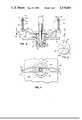
- FIG. 3is a fragmentary sectional view in elevation showing the apparatus in its aspirating mode
- FIG. 4is a fragmentary sectional view taken along the line IV--IV of FIG. 3;
- FIG. 5is a plan view of the cap used with the containers and which is affected by the stripper of this invention.
- FIG. 6is a fragmentary perspective frontal view of another embodiment of the invention.
- FIG. 7is a fragmentary sectional view taken horizontally generally through the line VII--VII shown as extending across the front surface of plate 300, FIG. 6, caps 100a, tray 20a and lever 350 having been omitted for clarity;
- FIG. 8is a fragmentary sectional view taken along the line VIII--VIII of FIG. 7 with a fragment of a capped container added for clarity;
- FIG. 9is a fragmentary perspective view similar to that of FIG. 6, but with the parts in their alternate position.
- the inventionis particularly useful in, and this description particularly recites, a clinical analyzer used to conduct colorimetric and potentiometric assays using the dried test elements noted in the patents set forth above. This description is most particularly directed to use in analyzers which feature a disposable tip as the storage unit for dispensing aspirated liquid.
- the inventionis useful in other apparatus wherein liquid to be analyzed is transferred from a capped container to a storage unit that penetrates the cap of the container.
- An analyzer 12such as that shown in FIG. 1 comprises two supply units 14 and 16 that feed or supply test elements to distributor means 30 to distribute or move the elements to the various stations 18, 22 and/or 24.
- One of the units 14 and 16supplies colorimetric test units, that is, those that detect the analyte concentration by a colorimetric reaction, and the other unit 14 or 16 supplies potentiometric test elements.
- Station 18is the liquid dispensing station, discussed in detail hereinafter.
- Stations 22 and 24are the respective incubators for colorimetric and potentiometric test elements.
- Detection stations 23 and 25provide means for detecting a change in the test element after the incubation period.
- one of stations 23 and 25includes a photometer constructed for colorimetric detection and the other includes a potentiometer.
- the details of units 14, 16, incubators 22, 24, detector stations 23, 25, and distributor 30are well known and are not critical. Useful examples of distributor 30 appear in U.S. Pat. No. 4,296,070, issued Oct. 20, 1981. Examples of incubator 22 and associated test element handling means appear in, e.g., U.S. Pat. No. 4,298,571, issued on Nov. 3, 1981.
- the patient liquidsare supplied to the analyzer in a plurality of separate containers 19, each having a cap 100 and each being supported in a tray 20 shaped as a quadrant of a circle, FIGS. 1 and 2.
- Trays 20also supply a plurality of disposable tip storage units 54.
- Such unitscomprise a cylindrical body 56 that terminates in a dispensing end 58 connected to body 56 by a cone portion 60, FIG. 3.
- the containers 19 and the tips 54are supported in respective apertures in the tray disposed as concentric arcs, the containers 19 preferably being disposed outside of the arc of tips 54.
- Trays 20in turn are suitably rotated past liquid dispensing station 18.
- Station 18comprises a vertically movable probe 51 on which tips 54 fit, one at a time.
- Probe 51is raised and lowered by a screw 42 and pinion 45, such pinion being driven by a motor 44.
- Shaft 42is mounted on a frame 32 that is slidably oscillated so as to move probe 51 and tip 54 through vertical plane A that extends out over and intercepts the two arcs in tray 20 along a radius thereof.
- Frame 32moves on rails 34, in response to automated commands from a microprocessor, not shown.
- Aspirating vacuum and dispensing pressureare supplied to probe 51 and thence to tip 54 by a pressure line 52. Further details of such a dispensing station are given in the aforesaid U.S. Pat. No. 4,287,155, the details of which are hereby incorporated by reference.
- the dispensing sequenceis that probe 51 picks up one of the tips 54 from tray 20, pushes through the cap of the container 19 aligned in plane A, aspirates the liquid, is withdrawn from container 19, and then moves over a test element 90 positioned by distributor 30 as shown for dispensing the liquid onto the test element. Thereafter the tip 54 is discarded into waste disposable bin 56, and test element 90 is inserted into one of the incubators.
- a cap stripper 110is provided for holding down cap 100 and container 19 against tray 20 each time one of the containers is moved into plane A for the aspiration step.
- Such strippercomprises arms 112 and 114 extending from the apparatus housing in a manner providing a fixed reference plane, and a dowl 116 slidably mounted within aperture 118 in each of the arms.
- Cotter pins 120 or the likeare used to keep the dowls from falling out of their arms.
- Each dowlis seated on an end of a D-shaped camming member 130 comprising, FIGS. 3 and 4, two strips 132, 134 joined together at opposite end portions 136 and 138 to which dowls 116 are attached.
- Strips 132 and 134are separated a distance sufficient to allow probe 51 to carry tip 54 down between them, FIG. 4.
- compression springs 140are mounted between portions 136 and 138 and the respective reference arms 112 and 114. The downward bias of the strips accommodates variances in the height of the caps 100 and/or in the height of containers 19.
- Arms 112 and 114are either permanently fixed against vertical movement, or alternatively, are mounted to a hood, not shown, that is fixed in place over the dispensing station 18 during dispensing but which pivots out of the way, along with stripper 110, when trays 20 are loaded or unloaded. In either case, the camming member 130 remains in place to hold down the caps against the tray surface, for a plurality of sequentially advanced containers.
- stripper 110is as follows--a capped container 19 is moved into position in plane A along the direction indicated by arrow 150, and as it does, cap 100 is cammed against its reference surface, tray 20, by reason of the sloped portion of strips 132 and 134. This in turn raises the strip (arrows 160) from the dotted position to that shown in solid, against the action of springs 140. Tip 54 is then pushed through cap 100, the latter having been scored as shown in FIG. 5 along lines 200 that form teeth 210. As shown in FIG. 3 teeth 210 tend to bind against tip 54.
- tip 54When tip 54 is withdrawn from both container 19 and its liquid, after aspiration, cap 100 is held by stripper 110 against container 19 and surface 20, and is prevented from following the upward movement of the withdrawing tip. As a result, the withdrawal of the exterior surface of tip 54 (a) from the liquid and (b) through the teeth 210 is maintained at a relatively slow and uniform rate. The withdrawal of the tip from the liquid and the cap at this relatively slow, uniform rate of withdrawal has been shown to be important in the reduction in the number of instances of perfusion, by a mechanism that is not clearly understood.
- the stripper of FIG. 3is useful even if it contacts the cap only for the withdrawal movement of tip 54. That is, strips 132 and 134 need not be placed in contact with cap 100 until just prior to the withdrawal movement of tip 54 from its aspirating position. To that end, arms 112 and 114 can be mounted, not shown, for movement into the position shown in FIG. 3 only just before the withdrawal movement of probe 51 and tip 54. Stripper 110 is of course retained in such position during the entire withdrawal movement of the probe and tip.
- FIGS. 6-9Another embodiment of the stripper is shown in FIGS. 6-9, wherein the cap stripper is moved into and away from its stripping position depending upon the position of the aspirating probe. Parts similar to those previously described bear the same reference numeral to which the distinguishing suffix "a" has been appended.
- containers with caps 100aare mounted in trays 20a for rotation past dispensing station 18a and under probe 51a carrying disposable tip 54a, as in the previously described embodiment.
- the frame at dispensing stations 18aincludes a fixed vertical plate 300 cut away at 301, FIG. 6, to allow probe 51a to move in plane A out over trays 20a, and back to a position above the test element, not shown, awaiting the liquid from tip 54a.
- the stripperis pivotally mounted for movement centered on plane A, from a position in which the stripper is horizontally disposed to hold down a capped container in place for aspiration, FIG. 6, to another position, FIG. 9, in which it is vertically disposed out of the way for movement of tray 20a.
- the strippercomprises a camming member 130a, FIGS. 6-8, welded to two arms 310 adjacent ends 312 of such arms, FIG. 7.
- Member 130aitself comprises two strips 132a and 134a.
- the opposite ends of arms 310are bent outwardly to form ears 316, 317 that extend behind frame 300, FIGS. 6 and 7.
- Mounting lugs 320extend downwardly from the underside of arms 310, FIG. 8, to journal camming member 130a to a pivot rod 330 fixed to frame 300 by screws 332.
- a torsion spring 340is mounted on rod 330 with one end 342 affixed to the back of frame 300, FIG. 7. The other end 344 of spring 340 is secured to the adjacent arm 310.
- spring 340is forced to wind up even further, thus tending to force camming member 130a back to its vertical position.
- lever 350is pivotally mounted on the back of frame 300, FIGS. 6 and 8, by a pivot screw 352.
- One end 354 of lever 350is apertured to receive one end of a tension spring 358 attached to ear 316 of arm 310, FIGS. 6-8.
- the opposite end 356 of lever 350extends into a position behind a slot 360 cut away in frame 300 for the movement of a trip arm 362.
- Trip arm 362is in turn mounted to be cammed downwardly as probe 51a is moved downwardly, thus forcing lever 350 to move clockwise from its position shown in FIG. 9, with end 356 raised, to that position shown in FIG. 6 wherein end 356 is lowered.
- End 354is thus raised and spring 358 is extended so as to pull against ear 316.
- the spring constants of springs 340 and 358are selected so that spring 358 overcomes the bias of spring 340, forcing arms 310 to pivot downwardly and thus to cam the positioned cap 19a and container against tray 20a.
- spring 358allows camming member 130a to accommodate variations in the heights of caps 100a or their containers.
- spring 358is sufficiently flexible as to allow trip arm 362 to depress lever 350 well beyond the point at which stripping means 130a is fully pressed against the cap to be pierced.
- overtravel of arm 362 and lever 350is preferred, so that when probe 51a, and thus trip arm 362, begin to withdraw from the capped container, spring 358 will still have enough residual tension as to hold down camming member 132a against cap 100a while tip 54a is being withdrawn by the probe.
- camming member 132adoes move away from the caps and the tray 20a with each withdrawal of probe 51a for dispensing but only after tip 54a has been fully disengaged from the cap.
Landscapes
- Physics & Mathematics (AREA)
- Health & Medical Sciences (AREA)
- Life Sciences & Earth Sciences (AREA)
- Chemical & Material Sciences (AREA)
- Analytical Chemistry (AREA)
- Biochemistry (AREA)
- General Health & Medical Sciences (AREA)
- General Physics & Mathematics (AREA)
- Immunology (AREA)
- Pathology (AREA)
- Automatic Analysis And Handling Materials Therefor (AREA)
- Sampling And Sample Adjustment (AREA)
Abstract
Description
Claims (6)
Priority Applications (4)
| Application Number | Priority Date | Filing Date | Title |
|---|---|---|---|
| US06/606,489US4539855A (en) | 1984-05-03 | 1984-05-03 | Apparatus for transferring liquid out of a capped container, and analyzer utilizing same |
| CA000467562ACA1252702A (en) | 1984-05-03 | 1984-11-13 | Apparatus for transferring liquid out of a capped container, and analyzer utilizing same |
| DE3515824ADE3515824C2 (en) | 1984-05-03 | 1985-05-02 | Automatic analyzer with a device for removing and dispensing liquid from a container |
| JP1985066440UJPS60193465U (en) | 1984-05-03 | 1985-05-02 | Device for transferring liquids from containers with caps |
Applications Claiming Priority (1)
| Application Number | Priority Date | Filing Date | Title |
|---|---|---|---|
| US06/606,489US4539855A (en) | 1984-05-03 | 1984-05-03 | Apparatus for transferring liquid out of a capped container, and analyzer utilizing same |
Publications (1)
| Publication Number | Publication Date |
|---|---|
| US4539855Atrue US4539855A (en) | 1985-09-10 |
Family
ID=24428179
Family Applications (1)
| Application Number | Title | Priority Date | Filing Date |
|---|---|---|---|
| US06/606,489Expired - LifetimeUS4539855A (en) | 1984-05-03 | 1984-05-03 | Apparatus for transferring liquid out of a capped container, and analyzer utilizing same |
Country Status (4)
| Country | Link |
|---|---|
| US (1) | US4539855A (en) |
| JP (1) | JPS60193465U (en) |
| CA (1) | CA1252702A (en) |
| DE (1) | DE3515824C2 (en) |
Cited By (39)
| Publication number | Priority date | Publication date | Assignee | Title |
|---|---|---|---|---|
| US4751052A (en)* | 1985-07-22 | 1988-06-14 | Sequoia-Turner Corporation | Tube alignment apparatus |
| US4797257A (en)* | 1987-07-20 | 1989-01-10 | Eastman Kodak Company | Slide holder and tip locator |
| US4803050A (en)* | 1985-07-22 | 1989-02-07 | Sequoia-Turner Corporation | Method and apparatus for liquid addition and aspiration in automated immunoassay techniques |
| US4857471A (en)* | 1987-07-20 | 1989-08-15 | Eastman Kodak Company | Analyzer with wash station separate from incubator |
| EP0383459A3 (en)* | 1989-02-14 | 1991-04-24 | Beckman Instruments, Inc. | Automated capillary injector |
| US5043141A (en)* | 1987-10-29 | 1991-08-27 | Cardiff Laboratories For Energy & Resources Limited | Injection systems for sample testing for luminometers |
| US5089229A (en)* | 1989-11-22 | 1992-02-18 | Vettest S.A. | Chemical analyzer |
| EP0444498A3 (en)* | 1990-02-28 | 1992-03-18 | The Perkin-Elmer Corporation | Vial locator and sensor |
| US5133392A (en)* | 1991-04-10 | 1992-07-28 | Eastman Kodak Company | Liquid injection using container bottom sensing |
| US5171530A (en)* | 1990-02-28 | 1992-12-15 | The Perkin-Elmer Corporation | Vial locator and sensor |
| US5194226A (en)* | 1989-10-18 | 1993-03-16 | Bodenseewerk Perkin-Elmer Gmbh | Dosing device for analyzing apparatus |
| EP0542319A1 (en)* | 1987-05-06 | 1993-05-19 | Abbott Laboratories | Sample ring for clinical analyser network |
| US5216926A (en)* | 1990-04-18 | 1993-06-08 | E. I. Du Pont De Nemours And Company | Closed and open tube sampling apparatus |
| US5250262A (en)* | 1989-11-22 | 1993-10-05 | Vettest S.A. | Chemical analyzer |
| EP0566196A1 (en)* | 1992-04-15 | 1993-10-20 | Johnson & Johnson Clinical Diagnostics, Inc. | Reservoirs |
| US5270211A (en)* | 1992-07-16 | 1993-12-14 | Schiapparelli Biosystems, Inc. | Sample tube entry port for a chemical analyzer |
| US5443791A (en)* | 1990-04-06 | 1995-08-22 | Perkin Elmer - Applied Biosystems Division | Automated molecular biology laboratory |
| US5514339A (en)* | 1989-04-07 | 1996-05-07 | Leopardi; Francesco | Stopper of analysis test tubes |
| US5582696A (en)* | 1994-05-31 | 1996-12-10 | Health Craft International, Inc. | Glucose level monitoring apparatus |
| USD457247S1 (en) | 2000-05-12 | 2002-05-14 | Gen-Probe Incorporated | Cap |
| US20020127147A1 (en)* | 2001-03-09 | 2002-09-12 | Kacian Daniel L. | Penetrable cap |
| US6537818B2 (en)* | 1998-02-27 | 2003-03-25 | Ventana Medical Systems, Inc. | System and method of aspirating and dispensing reagent |
| US6716396B1 (en) | 1999-05-14 | 2004-04-06 | Gen-Probe Incorporated | Penetrable cap |
| US20050191760A1 (en)* | 1997-09-17 | 2005-09-01 | Heath Ellen M. | Apparatuses and methods for isolating nucleic acid |
| US7144554B1 (en)* | 2002-08-02 | 2006-12-05 | Hamilton Company | Ultra low volume probe |
| US7270785B1 (en) | 2001-11-02 | 2007-09-18 | Ventana Medical Systems, Inc. | Automated molecular pathology apparatus having fixed slide platforms |
| US7273591B2 (en) | 2003-08-12 | 2007-09-25 | Idexx Laboratories, Inc. | Slide cartridge and reagent test slides for use with a chemical analyzer, and chemical analyzer for same |
| US7303725B2 (en) | 2002-04-15 | 2007-12-04 | Ventana Medical Systems, Inc. | Automated high volume slide staining system |
| US7378055B2 (en) | 2002-04-26 | 2008-05-27 | Ventana Medical Systems, Inc. | Automated molecular pathology apparatus having fixed slide platforms |
| US7468161B2 (en) | 2002-04-15 | 2008-12-23 | Ventana Medical Systems, Inc. | Automated high volume slide processing system |
| US20110239793A1 (en)* | 2010-03-31 | 2011-10-06 | Fujifilm Corporation | Extraction method, extraction vessel for use with the same, extraction kit and valve expansion member |
| US8585989B2 (en) | 2003-12-04 | 2013-11-19 | Idexx Laboratories, Inc. | Retaining clip for reagent test slides |
| US9116129B2 (en) | 2007-05-08 | 2015-08-25 | Idexx Laboratories, Inc. | Chemical analyzer |
| US9513197B2 (en)* | 2014-11-07 | 2016-12-06 | Theranos, Inc. | Methods, devices, and systems for mixing fluids |
| US9797916B2 (en) | 2014-01-10 | 2017-10-24 | Idexx Laboratories, Inc. | Chemical analyzer |
| US10184862B2 (en) | 2008-11-12 | 2019-01-22 | Ventana Medical Systems, Inc. | Methods and apparatuses for heating slides carrying specimens |
| US10794805B2 (en) | 2013-12-13 | 2020-10-06 | Ventana Medical Systems, Inc. | Automated histological processing of biological specimens and associated technology |
| US11249095B2 (en) | 2002-04-15 | 2022-02-15 | Ventana Medical Systems, Inc. | Automated high volume slide processing system |
| US11977091B2 (en) | 2020-07-10 | 2024-05-07 | Idexx Laboratories Inc. | Point-of-care medical diagnostic analyzer and devices, systems, and methods for medical diagnostic analysis of samples |
Families Citing this family (7)
| Publication number | Priority date | Publication date | Assignee | Title |
|---|---|---|---|---|
| JP2585740B2 (en)* | 1987-11-12 | 1997-02-26 | 株式会社日立製作所 | Automatic analyzers and reaction vessels |
| US5213761A (en)* | 1989-04-12 | 1993-05-25 | Olympus Optical Co., Ltd. | Automatic chemical analyzer having an improved delivery mechanism |
| DE3938559A1 (en)* | 1989-11-21 | 1991-05-23 | Boehringer Mannheim Gmbh | REAGENT STORAGE SYSTEM FOR A MEDICAL ANALYZER |
| CA2130129A1 (en)* | 1993-09-10 | 1995-03-11 | Martin Walter Ellenberger | Closure having an array of piercable places |
| CA2130013C (en)* | 1993-09-10 | 1999-03-30 | Rolf Moser | Apparatus for automatic performance of temperature cycles |
| DE29704543U1 (en)* | 1997-03-13 | 1997-05-07 | Macherey, Nagel & Co, 52355 Düren | Separation device for the separation of substances |
| DE19854919A1 (en)* | 1998-11-27 | 2000-06-15 | Luigs & Neumann Feinmechanik U | Work place for microbiological tests |
Citations (7)
| Publication number | Priority date | Publication date | Assignee | Title |
|---|---|---|---|---|
| US3992158A (en)* | 1973-08-16 | 1976-11-16 | Eastman Kodak Company | Integral analytical element |
| US4053381A (en)* | 1976-05-19 | 1977-10-11 | Eastman Kodak Company | Device for determining ionic activity of components of liquid drops |
| US4258001A (en)* | 1978-12-27 | 1981-03-24 | Eastman Kodak Company | Element, structure and method for the analysis or transport of liquids |
| US4287155A (en)* | 1980-06-16 | 1981-09-01 | Eastman Kodak Company | Sample tray and carrier for chemical analyzer |
| US4340390A (en)* | 1980-06-16 | 1982-07-20 | Eastman Kodak Company | Method and apparatus for metering biological fluids |
| US4347875A (en)* | 1980-07-14 | 1982-09-07 | Eastman Kodak Company | Self-cleaning nozzle construction for aspirators |
| US4495149A (en)* | 1981-09-18 | 1985-01-22 | Toa Medical Electronic Co., Ltd. | Optical-type automatic analyzing and measuring apparatus |
Family Cites Families (6)
| Publication number | Priority date | Publication date | Assignee | Title |
|---|---|---|---|---|
| US3508442A (en)* | 1968-09-18 | 1970-04-28 | Hewlett Packard Co | Automatic liquid sampler for chromatography |
| US4298571A (en)* | 1976-12-17 | 1981-11-03 | Eastman Kodak Company | Incubator including cover means for an analysis slide |
| US4274453A (en)* | 1979-02-21 | 1981-06-23 | Southland Instruments, Inc. | Aseptic fluid transfer |
| US4311484A (en)* | 1980-04-09 | 1982-01-19 | Cortex Research Corporation | Specimen sampling apparatus |
| US4296070A (en)* | 1980-06-16 | 1981-10-20 | Eastman Kodak Company | Slide distributor for a chemical analyzer |
| US4387076A (en)* | 1981-10-14 | 1983-06-07 | Coulter Electronics, Inc. | Sample feeding arrangement |
- 1984
- 1984-05-03USUS06/606,489patent/US4539855A/ennot_activeExpired - Lifetime
- 1984-11-13CACA000467562Apatent/CA1252702A/ennot_activeExpired
- 1985
- 1985-05-02DEDE3515824Apatent/DE3515824C2/ennot_activeExpired - Fee Related
- 1985-05-02JPJP1985066440Upatent/JPS60193465U/enactiveGranted
Patent Citations (7)
| Publication number | Priority date | Publication date | Assignee | Title |
|---|---|---|---|---|
| US3992158A (en)* | 1973-08-16 | 1976-11-16 | Eastman Kodak Company | Integral analytical element |
| US4053381A (en)* | 1976-05-19 | 1977-10-11 | Eastman Kodak Company | Device for determining ionic activity of components of liquid drops |
| US4258001A (en)* | 1978-12-27 | 1981-03-24 | Eastman Kodak Company | Element, structure and method for the analysis or transport of liquids |
| US4287155A (en)* | 1980-06-16 | 1981-09-01 | Eastman Kodak Company | Sample tray and carrier for chemical analyzer |
| US4340390A (en)* | 1980-06-16 | 1982-07-20 | Eastman Kodak Company | Method and apparatus for metering biological fluids |
| US4347875A (en)* | 1980-07-14 | 1982-09-07 | Eastman Kodak Company | Self-cleaning nozzle construction for aspirators |
| US4495149A (en)* | 1981-09-18 | 1985-01-22 | Toa Medical Electronic Co., Ltd. | Optical-type automatic analyzing and measuring apparatus |
Cited By (82)
| Publication number | Priority date | Publication date | Assignee | Title |
|---|---|---|---|---|
| US4803050A (en)* | 1985-07-22 | 1989-02-07 | Sequoia-Turner Corporation | Method and apparatus for liquid addition and aspiration in automated immunoassay techniques |
| US4751052A (en)* | 1985-07-22 | 1988-06-14 | Sequoia-Turner Corporation | Tube alignment apparatus |
| EP0542319A1 (en)* | 1987-05-06 | 1993-05-19 | Abbott Laboratories | Sample ring for clinical analyser network |
| US4797257A (en)* | 1987-07-20 | 1989-01-10 | Eastman Kodak Company | Slide holder and tip locator |
| US4857471A (en)* | 1987-07-20 | 1989-08-15 | Eastman Kodak Company | Analyzer with wash station separate from incubator |
| US5043141A (en)* | 1987-10-29 | 1991-08-27 | Cardiff Laboratories For Energy & Resources Limited | Injection systems for sample testing for luminometers |
| EP0383459A3 (en)* | 1989-02-14 | 1991-04-24 | Beckman Instruments, Inc. | Automated capillary injector |
| US5514339A (en)* | 1989-04-07 | 1996-05-07 | Leopardi; Francesco | Stopper of analysis test tubes |
| US5194226A (en)* | 1989-10-18 | 1993-03-16 | Bodenseewerk Perkin-Elmer Gmbh | Dosing device for analyzing apparatus |
| US5089229A (en)* | 1989-11-22 | 1992-02-18 | Vettest S.A. | Chemical analyzer |
| US5336467A (en) | 1989-11-22 | 1994-08-09 | Vettest S.A. | Chemical analyzer |
| US5250262A (en)* | 1989-11-22 | 1993-10-05 | Vettest S.A. | Chemical analyzer |
| US5171530A (en)* | 1990-02-28 | 1992-12-15 | The Perkin-Elmer Corporation | Vial locator and sensor |
| EP0444498A3 (en)* | 1990-02-28 | 1992-03-18 | The Perkin-Elmer Corporation | Vial locator and sensor |
| AU640453B2 (en)* | 1990-02-28 | 1993-08-26 | Perkin-Elmer Corporation, The | Apparatus for automatically locating vials in an analytical instrument |
| US5443791A (en)* | 1990-04-06 | 1995-08-22 | Perkin Elmer - Applied Biosystems Division | Automated molecular biology laboratory |
| US5216926A (en)* | 1990-04-18 | 1993-06-08 | E. I. Du Pont De Nemours And Company | Closed and open tube sampling apparatus |
| US5133392A (en)* | 1991-04-10 | 1992-07-28 | Eastman Kodak Company | Liquid injection using container bottom sensing |
| EP0566196A1 (en)* | 1992-04-15 | 1993-10-20 | Johnson & Johnson Clinical Diagnostics, Inc. | Reservoirs |
| US5270211A (en)* | 1992-07-16 | 1993-12-14 | Schiapparelli Biosystems, Inc. | Sample tube entry port for a chemical analyzer |
| US5582696A (en)* | 1994-05-31 | 1996-12-10 | Health Craft International, Inc. | Glucose level monitoring apparatus |
| US20050191760A1 (en)* | 1997-09-17 | 2005-09-01 | Heath Ellen M. | Apparatuses and methods for isolating nucleic acid |
| US7776616B2 (en)* | 1997-09-17 | 2010-08-17 | Qiagen North American Holdings, Inc. | Apparatuses and methods for isolating nucleic acid |
| US6537818B2 (en)* | 1998-02-27 | 2003-03-25 | Ventana Medical Systems, Inc. | System and method of aspirating and dispensing reagent |
| US7648680B2 (en) | 1999-05-14 | 2010-01-19 | Gen-Probe Incorporated | Method for accessing the contents of a closed vessel containing a specimen retrieval device |
| US7795036B2 (en) | 1999-05-14 | 2010-09-14 | Gen-Probe Incorporated | Method for accessing the contents of a closed collection device |
| US6806094B2 (en) | 1999-05-14 | 2004-10-19 | Gen-Probe Incorporated | Method for removing a fluid substance from a collection device |
| US8038967B2 (en) | 1999-05-14 | 2011-10-18 | Gen-Probe Incorporated | Method for accessing the contents of a closed vessel containing a specimen retrieval device |
| US8206662B2 (en) | 1999-05-14 | 2012-06-26 | Gen-Probe Incorporated | Collection device including a penetrable cap having an absorbent pile fabric |
| US6716396B1 (en) | 1999-05-14 | 2004-04-06 | Gen-Probe Incorporated | Penetrable cap |
| US7927549B2 (en) | 1999-05-14 | 2011-04-19 | Gen-Probe Incorporated | Method for accessing the contents of a closed collection device with a modified pipette tip |
| US7435389B2 (en) | 1999-05-14 | 2008-10-14 | Gen-Probe Incorporated | Sealed collection device having striated cap |
| US8573072B2 (en) | 1999-05-14 | 2013-11-05 | Gen-Probe Incorporated | Method for removing a fluid substance from a sealed collection device |
| US7276383B2 (en) | 1999-05-14 | 2007-10-02 | Gen-Probe Incorporated | Method for obtaining the contents of a fluid-holding vessel |
| US8211710B2 (en) | 1999-05-14 | 2012-07-03 | Dickey Kathleen A | Method for accessing the contents of a closed collection device |
| US8535621B2 (en) | 1999-05-14 | 2013-09-17 | Gen-Probe Incorporated | Penetrable cap having rib structures |
| US7309469B2 (en) | 1999-05-14 | 2007-12-18 | Gen-Probe Incorporated | Collection device |
| US8334145B2 (en) | 1999-05-14 | 2012-12-18 | Gen-Probe Incorporated | Pierceable cap having spaced-apart grooves |
| US6723289B2 (en) | 1999-05-14 | 2004-04-20 | Gen-Probe Incorporated | Fluid transfer device |
| USD457247S1 (en) | 2000-05-12 | 2002-05-14 | Gen-Probe Incorporated | Cap |
| US7294308B2 (en) | 2001-03-09 | 2007-11-13 | Gen-Probe Incorporated | Penetrable cap |
| US20020127147A1 (en)* | 2001-03-09 | 2002-09-12 | Kacian Daniel L. | Penetrable cap |
| US7691332B2 (en) | 2001-03-09 | 2010-04-06 | Gen-Probe Incorporated | Penetrable cap |
| US8052944B2 (en) | 2001-03-09 | 2011-11-08 | Gen-Probe Incorporated | Penetrable cap |
| US8685347B2 (en) | 2001-03-09 | 2014-04-01 | Gen-Probe Incorporated | Penetrable cap |
| US7824922B2 (en) | 2001-03-09 | 2010-11-02 | Gen-Probe Incorporated | Method for removing a fluid substance from a closed system |
| USRE45194E1 (en) | 2001-03-09 | 2014-10-14 | Gen-Probe Incorporated | Penetrable cap |
| US6893612B2 (en) | 2001-03-09 | 2005-05-17 | Gen-Probe Incorporated | Penetrable cap |
| US20050079633A1 (en)* | 2001-03-09 | 2005-04-14 | Gen-Probe Incorporated | Method for transferring a substance to or from a closed system |
| US8057762B2 (en) | 2001-03-09 | 2011-11-15 | Gen-Probe Incorporated | Penetrable cap |
| US7404927B2 (en) | 2001-11-02 | 2008-07-29 | Ventana Medical Systems, Inc. | Automated molecular pathology apparatus having fixed slide platforms |
| US7270785B1 (en) | 2001-11-02 | 2007-09-18 | Ventana Medical Systems, Inc. | Automated molecular pathology apparatus having fixed slide platforms |
| US11249095B2 (en) | 2002-04-15 | 2022-02-15 | Ventana Medical Systems, Inc. | Automated high volume slide processing system |
| US7468161B2 (en) | 2002-04-15 | 2008-12-23 | Ventana Medical Systems, Inc. | Automated high volume slide processing system |
| US11092611B2 (en) | 2002-04-15 | 2021-08-17 | Ventana Medical Systems, Inc. | Automated high volume slide processing system |
| US10302665B2 (en) | 2002-04-15 | 2019-05-28 | Ventana Medical Systems, Inc. | Automated high volume slide processing system |
| US7303725B2 (en) | 2002-04-15 | 2007-12-04 | Ventana Medical Systems, Inc. | Automated high volume slide staining system |
| US8048373B2 (en) | 2002-04-15 | 2011-11-01 | Ventana Medical Systems, Inc. | Automated high volume slide staining system |
| US9528918B2 (en) | 2002-04-15 | 2016-12-27 | Ventana Medical Systems, Inc. | Automated high volume slide processing system |
| US8663991B2 (en) | 2002-04-15 | 2014-03-04 | Ventana Medical Systems, Inc. | Automated high volume slide processing system |
| US7378055B2 (en) | 2002-04-26 | 2008-05-27 | Ventana Medical Systems, Inc. | Automated molecular pathology apparatus having fixed slide platforms |
| US7144554B1 (en)* | 2002-08-02 | 2006-12-05 | Hamilton Company | Ultra low volume probe |
| US7273591B2 (en) | 2003-08-12 | 2007-09-25 | Idexx Laboratories, Inc. | Slide cartridge and reagent test slides for use with a chemical analyzer, and chemical analyzer for same |
| US8287823B2 (en) | 2003-08-12 | 2012-10-16 | Idexx Laboratories, Inc. | Slide cartridge and reagent test slides for use with a chemical analyzer, and chemical analyzer for same |
| US8585989B2 (en) | 2003-12-04 | 2013-11-19 | Idexx Laboratories, Inc. | Retaining clip for reagent test slides |
| US10900982B2 (en) | 2005-04-27 | 2021-01-26 | Ventana Medical Systems, Inc. | Automated high volume slide processing system |
| US11815518B2 (en) | 2005-04-27 | 2023-11-14 | Ventana Medical Systems, Inc. | Automated high volume slide processing system |
| US9823109B2 (en) | 2007-05-08 | 2017-11-21 | Idexx Laboratories, Inc. | Chemical analyzer |
| US9116129B2 (en) | 2007-05-08 | 2015-08-25 | Idexx Laboratories, Inc. | Chemical analyzer |
| US10429280B2 (en) | 2008-11-12 | 2019-10-01 | Ventana Medical Systems, Inc. | Methods for heating microscope slides carrying specimens |
| US10520403B2 (en) | 2008-11-12 | 2019-12-31 | Ventana Medical Systems, Inc. | Apparatuses for heating microscope slides carrying specimens |
| US10184862B2 (en) | 2008-11-12 | 2019-01-22 | Ventana Medical Systems, Inc. | Methods and apparatuses for heating slides carrying specimens |
| US11493410B2 (en) | 2008-11-12 | 2022-11-08 | Ventana Medical Systems, Inc. | Methods for heating microscope slides carrying specimens |
| US8474337B2 (en)* | 2010-03-31 | 2013-07-02 | Fujifilm Corporation | Extraction method, extraction vessel for use with the same, extraction kit and valve expansion member |
| US20110239793A1 (en)* | 2010-03-31 | 2011-10-06 | Fujifilm Corporation | Extraction method, extraction vessel for use with the same, extraction kit and valve expansion member |
| US10794805B2 (en) | 2013-12-13 | 2020-10-06 | Ventana Medical Systems, Inc. | Automated histological processing of biological specimens and associated technology |
| US11614387B2 (en) | 2013-12-13 | 2023-03-28 | Ventana Medical Systems, Inc. | Automated histological processing of biological specimens and associated technology |
| US12181389B2 (en) | 2013-12-13 | 2024-12-31 | Ventana Medical Systems, Inc. | Automated histological processing of biological specimens and associated technology |
| US9797916B2 (en) | 2014-01-10 | 2017-10-24 | Idexx Laboratories, Inc. | Chemical analyzer |
| US10114033B2 (en) | 2014-11-07 | 2018-10-30 | Theranos Ip Company, Llc | Methods, devices, and systems for mixing fluids |
| US9513197B2 (en)* | 2014-11-07 | 2016-12-06 | Theranos, Inc. | Methods, devices, and systems for mixing fluids |
| US11977091B2 (en) | 2020-07-10 | 2024-05-07 | Idexx Laboratories Inc. | Point-of-care medical diagnostic analyzer and devices, systems, and methods for medical diagnostic analysis of samples |
Also Published As
| Publication number | Publication date |
|---|---|
| JPS60193465U (en) | 1985-12-23 |
| JPH0244213Y2 (en) | 1990-11-22 |
| DE3515824C2 (en) | 1994-02-10 |
| CA1252702A (en) | 1989-04-18 |
| DE3515824A1 (en) | 1985-11-07 |
Similar Documents
| Publication | Publication Date | Title |
|---|---|---|
| US4539855A (en) | Apparatus for transferring liquid out of a capped container, and analyzer utilizing same | |
| EP0382817B1 (en) | System for providing access to sealed containers | |
| US5676910A (en) | Automatic blood film preparation device | |
| US4298570A (en) | Tray section for automated sample handling apparatus | |
| US5271897A (en) | Device for raising and lowering covers of containers filled with liquid to be analyzed | |
| US6257091B1 (en) | Automatic decapper | |
| US8354078B2 (en) | Liquid aspirating tube, liquid dispensing apparatus and liquid dispensing method | |
| US5174960A (en) | Apparatus for shuttling a test element from a discharge path to a wash station | |
| CA1284871C (en) | Pipetting device having an automatic mechanism for replacing nozzle tips | |
| EP0098773A1 (en) | Apparatus for storing and dispensing analysis slides | |
| EP0513618A2 (en) | Metering device for slide analysis system | |
| US6531096B1 (en) | Method and apparatus for automatically opening and closing vial lids | |
| JP2000131329A (en) | Automatic sample handler for analytical equipment for container supply | |
| EP2672271A1 (en) | Automatic analysis system | |
| WO2008030755A1 (en) | Micro-sample cup rack adapter | |
| DE69526881T2 (en) | Device for reading and removing reaction cells in an incubator | |
| US20250244352A1 (en) | Disposable pipette tip management | |
| US5026526A (en) | Automated capping means for analyzer pipette | |
| US8507280B2 (en) | Method of normalizing surface tension of a sample fluid | |
| CN101275968A (en) | Liquid preparation device, liquid preparation method and liquid suction pipe | |
| US5242659A (en) | Device for feeding objects into a waste bin of an analyzer | |
| JPH0694729A (en) | Compound analyzer for clinic | |
| US20180011119A1 (en) | Transport of liquid containers in an automated analyzer | |
| JPH0718886B2 (en) | Pipette device with automatic nozzle chip exchange mechanism | |
| JPH09113518A (en) | Dispensing device |
Legal Events
| Date | Code | Title | Description |
|---|---|---|---|
| AS | Assignment | Owner name:EASTMAN KODAK COMPANY, ROCHESTER, NY, A CORP. OF N Free format text:ASSIGNMENT OF ASSIGNORS INTEREST.;ASSIGNOR:JACOBS, MERRIT N.;REEL/FRAME:004418/0732 Effective date:19840502 Owner name:EASTMAN KODAK COMPANY, A CORP. OF NEW JERSEY,NEW Y Free format text:ASSIGNMENT OF ASSIGNORS INTEREST;ASSIGNOR:JACOBS, MERRIT N.;REEL/FRAME:004418/0732 Effective date:19840502 | |
| STCF | Information on status: patent grant | Free format text:PATENTED CASE | |
| FEPP | Fee payment procedure | Free format text:PAYOR NUMBER ASSIGNED (ORIGINAL EVENT CODE: ASPN); ENTITY STATUS OF PATENT OWNER: LARGE ENTITY | |
| FPAY | Fee payment | Year of fee payment:4 | |
| FPAY | Fee payment | Year of fee payment:8 | |
| FEPP | Fee payment procedure | Free format text:PAYER NUMBER DE-ASSIGNED (ORIGINAL EVENT CODE: RMPN); ENTITY STATUS OF PATENT OWNER: LARGE ENTITY Free format text:PAYOR NUMBER ASSIGNED (ORIGINAL EVENT CODE: ASPN); ENTITY STATUS OF PATENT OWNER: LARGE ENTITY | |
| AS | Assignment | Owner name:CLINICAL DIAGNOSTIC SYSTEMS INC., NEW YORK Free format text:ASSIGNMENT OF ASSIGNORS INTEREST;ASSIGNOR:EASTMAN KODAK COMPANY;REEL/FRAME:007453/0348 Effective date:19950118 |