US4538264A - Self-repairing ring communications network - Google Patents
Self-repairing ring communications networkDownload PDFInfo
- Publication number
- US4538264A US4538264AUS06/466,108US46610883AUS4538264AUS 4538264 AUS4538264 AUS 4538264AUS 46610883 AUS46610883 AUS 46610883AUS 4538264 AUS4538264 AUS 4538264A
- Authority
- US
- United States
- Prior art keywords
- signal path
- inbound
- signal
- path
- riu
- Prior art date
- Legal status (The legal status is an assumption and is not a legal conclusion. Google has not performed a legal analysis and makes no representation as to the accuracy of the status listed.)
- Expired - Lifetime
Links
Images


Classifications
- H—ELECTRICITY
- H04—ELECTRIC COMMUNICATION TECHNIQUE
- H04L—TRANSMISSION OF DIGITAL INFORMATION, e.g. TELEGRAPHIC COMMUNICATION
- H04L12/00—Data switching networks
- H04L12/28—Data switching networks characterised by path configuration, e.g. LAN [Local Area Networks] or WAN [Wide Area Networks]
- H04L12/42—Loop networks
- H04L12/437—Ring fault isolation or reconfiguration
Definitions
- the present inventionis in the field of data communications, and more particularly relates to ring communications networks.
- Ring communications networksgenerally include a plurality of terminals coupled in series along a unidirectional signal path.
- any of the terminals coupled to the ringmay transmit or receive data on the ring according to a ring protocol.
- Ring communication systemsare relatively efficient to implement in terms of modularity, costs, and logical complexity. However, such systems are often subject to failure, principally due to a single failure or fault along the ring. There have been several approaches in the prior art to minimize the effects of this problem which utilize a pair of oppositely directed ring communication paths. See, for example, U.S. Pat. No. Re. 28,958, and D. J. Paulish, "A Fail-Safe Distributed Processing System", IEEE.
- the present inventionis directed to a ring communications network.
- the networkincludes a pair of oppositely directed, substantially parallel signal paths with a plurality of interface units (IU's) coupled in series along the pair of signal paths.
- Each IUhas two nearest neighbor IU's on the serially connected ring.
- Each local IUthus has an inbound and outbound signal path coupled to a neighbor IU on one side (e.g. right), and an inbound and an outbound signal path coupled to a neighbor IU on the other side.
- Each local IUincludes a detector for determining when the two inbound signal paths coupled to that IU are operative. In response to that detection, the IU couples the inbound signal paths to the outbound signal paths so that a signal from the neighbor on one side of the local IU is coupled to the neighbor on the other side of the local IU.
- the local IUfurther includes a detector for determining when an inbound signal path coupled to that IU is inoperative. In response to such a detection, the other inbound signal path is coupled to its parallel outbound signal path so that signals received from its neighbor IU are reflected back to that neighbor IU.
- the local IUautomatically caps the twin ring signal paths coming from its other neighbor IU.
- a similar operationoccurs at an IU on the other side of the fault, so that a ring is established in the fault-free portions of the twin ring network.
- a reconnect networkWhen such a reconfiguration is performed (due to detection of a fault on one of the inbound signal paths), a reconnect network becomes automatically operative.
- the reconnect networkperiodically transmits a reference signal on the outbound signal path in the direction of the fault, i.e. along the outbound signal path parallel to the inoperative inbound signal path.
- the period of this reconnect attemptis denoted T 0 .
- the reference signalhas a duration of at least T 1 , where T 1 is less than T 0 .
- the reconnect networkalso includes a monitor for the inoperative inbound signal path. In response to the detection of a reference signal on that signal path, the reconnect network controls the reference signal to continue to be transmitted. If no reference signal is detected, the transmission is terminated after the T 1 period.
- the reconnect networkis further operative for a duration T 2 following the detection of the reference signal on the inoperative inbound signal path to determine whether the detected reference signal has a duration at least equal to T 2 , where T 2 is greater than T 1 and T 2 is less than T 0 . In response to this determination, the reconnect network determines that the fault has been corrected, and re-couples the "inoperative" inbound signal paths to an outbound signal path.
- the IUwhen there are no faults detected to the "right” or "left", the IU receives and passes through signals on the inbound signal paths from its right and left. However, in response to a detection of a loss of integrity of the data path on one of those inbound signal paths (due either to a failure in the medium itself, or in an upstream IU) the IU automatically "caps" the operable portion of the network. While the operable portion is capped, the IU periodically checks to determine whether or not the fault has been corrected, and if so, reconfigures the overall system by uncapping the previously capped portion and returning the network to its original operative state.
- a ring communciations networkincludes a plurality of cluster interface units (CIU's), where each cluster interface unit (CIU) is coupled to a unidirectional, open loop signal path having one or more terminals coupled in series along that loop signal path.
- Each CIUincludes an input port and an output port respectively coupled to corresponding input and output ports of the open loop signal path.
- the networkincludes a corresponding plurality of ring interface units (RIU's) where each RIU is associated with one of the CIU's.
- RIU'sring interface units
- the networkfurther includes a corresponding plurality of pairs of oppositely directed, unidirectional, substantially parallel signal path segments.
- Each of the signal path segmentsextends between and couples two adjacent RIU's so that each RIU is coupled to a first neighbor RIU by one pair of signal paths and a second neighbor by another pair of signal paths.
- the first of the two pairs of signal path segments coupled to the RIUprovides a first inbound path segment for that local RIU.
- the second of the two pairs coupled to the RIUprovides a second inbound path segment to that local RIU and a substantially parallel first outbound path segment to that RIU.
- the first pairalso provides a second outbound path segment to that local RIU which is substantially parallel to the first inbound path segment.
- Each of the RIU'sincludes a detector for determining the presence or absence of predetermined signals on the first and second inbound path segments coupled to that RIU.
- These signalsmay be carrier signals in a modulated carrier system, or may be synchronization characters in a base band system. In alternative systems, a differential Manchester coding may be used, thereby providing the predetermined signal. In still other systems, separate pilot tones may be used. In response to such detection, one of four control signals is generated. For a modulated carrier system, the first of the four control signals is representative of the detection of the presence of a carrier signal on both the first and second inbound path segments.
- the second control signalis representative of the detection of the presence of a carrier signal on the first inbound path signal and the absence of such a carrier signal on the second inbound path segment.
- the third control signalis representative of the detection of the absence of a carrier signal on the first inbound path segment and the presence of a carrier signal on the second inbound path segment.
- the fourth control signalis representative of the absence of a carrier signal on both of the first and second inbound path segments.
- the RIUfurther includes a selectively operable network which is responsive to the first control signal for coupling the associated CIU input port to the first inbound path segment and for coupling the associated CIU output port to the first outbound path segment, and for coupling the second inbound path segment to the second outbound path segment.
- the RIUis selectively operable in response to the second control signal for coupling the associated CIU input port to the first inbound path segment and for coupling the associated CIU output port to the second outbound path segment.
- the RIUis selectively operable in response to the third control signal for coupling the associated CIU input port to the second inbound path segment and for coupling the associated CIU output port to the first outbound path segment.
- the RIUis further selectively operable in response to the fourth control signal for coupling the associated CIU input port to the associated CIU output port.
- the RIUmay detect faults in the ring communications network and isolate those faults by reconfiguring the network so that a communications ring is established excluding the fault areas. This process is performed automatically. Furthermore, the RIU is expressly adapted to identify when faults exist both to the left and right of that RIU, and in such cases to automatically cap, or close, the loop which is coupled to the CIU, thereby permitting the cluster of terminals coupled to that loop to operate in a ring configuration, independent of these faults on the overall inter-RIU twin ring network. This latter configuration is particularly important in distributed networks where relatively high terminal densities are provided in clusters coupled by way of CIU's and RIU's.
- the present inventionperiodically (and automatically) determines whether faults have been corrected and at such points in time reconfigures the network to the original state.
- terminalsmay also be coupled to the networks so that data may be entered and removed from the network in a conventional manner.
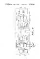
- FIG. 1shows in block diagram form an exemplary ring communications network in accordance with the present invention
- FIGS. 2-5illustrate the functional interconnections of the signal paths of the network of FIG. 1;
- FIG. 6illustrates a functional interconnection of the signal paths of an alternative network configuration embodying this invention
- FIG. 7shows,in block diagram form, an exemplary pair of adjacent ring interface units in a carrier-based ring network in accordance with the present invention.
- FIG. 8shows,in block diagram form, an exemplary pair of adjacent ring interface units in a baseband ring network in accordance with the present invention.
- FIG. 1shows a ring communications network 10 in accordance with the present invention.
- the exemplary network 10includes four ring interface units (RIU's) 12, 14, 16 and 18.
- RIU'sring interface units
- Four pairs of oppositely directed, unidirectional signal path segments 20, 22, 24 and 26extend between and couple the respective RIU's.
- the segments of each pairare denoted in FIG. 1 with the reference designation for the pair plus a subscript "a" or "b". As shown, the "a" segments form a counter clockwise "ring”and the "b” segments form a clockwise ring.
- the RIU 12is coupled to RIU 14 by an inbound path segment 20a and a substantially parallel outbound path segment 20b.
- RIU 12is also coupled to RIU 18 by an inbound path segment 26b and a substantially parallel outbound path segment 26a.
- Each of the other RIU'sis similarly configured.
- the network 10is a modulated carrier system where the "a" and "b" signal path segments are each channels on a single broadband cable.
- Different signal path mediamay be used such as optical fibers, or the like.
- network 10further includes a cluster interface unit 40 having an input port 42 and an output port 44 coupled to the RIU 12.
- the CIU 40has its respective input and output ports 42 and 44 coupled by a unidirectional open loop signal path 50 with five loop interface units (LIU's) 52, 54, 56, 58 and 60 coupled in series along the loop signal path 50.
- LIU'smay access the path 50, for example, as in a token-passing ring communications network. Additional devices may be coupled to the various LIU's.
- the RIU 12as described in detail below, is adapted to detect the presence or absence of a carrier signal on its inbound path segments 20a and 26b.
- the RIU 12In response to that detection, the RIU 12 generates one of four control signals C1, C2, C3 and C4.
- the control signal C1is representative of the detection of the presence of a carrier signal on both inbound path segments 20a and 26b.
- the second control signal C2is representative of the detection of the presence of the carrier signal on path segment 20a and the absence of a carrier signal on path 26b.
- the third control signal C3is representative of the detection of the presence of a carrier on path segment 26b and the absence of a carrier signal on path segment 20a.
- the fourth control signal C4is representative of the detection of the absence of the carrier signal on both of the path segments 20a and 26b.
- C2, C3 and C4are indicative of a fault, and, once generated, remain in efrect until the fault is no longer present.
- RIU 12determines which control signal is appropriate for the current state of the network 10
- RIU 12controls a switching interconnection of the signal paths 20 and 26 as shown functionally in FIGS. 2-5 in accordance with those control signals C1-C4, respectively.
- the path segments 20b and 26bare directly coupled, and the inbound path segment 20a is coupled to input port 42 of CIU 40 and the output port 44 of CIU 40 is coupled to the outbound patn 26a.
- the loop 50 and the LIU'sare coupled in series with the path segments 26a and 20a. This represents "normal" (fault-free) operation of the network 10, with respect to RIU 12.
- inbound path 26bis coupled to input port 42 and output port 44 is coupled to outbound path segment 26a. Carrier is suppressed on path 20b. Thus, the paths 20a and 20b are decoupled.
- the control signal C3indicates a failure to detect carrier on line 20a, and thus indicates a fault in that direction, i.e., to the "left" of RIU 12.
- the loop 50in effect caps the end of the loop so that inbound signals on path 26b are passed around the loop 50 and back to the outbound path 26a.
- a similar operationwill occur at another RIU in network 10 to cap paths 26a and 26b to the right (as shown) of RIU 12, thereby forming a communications ring excluding the faulty link.
- RIU 12in response to control signal C2, RIU 12 operates in a similar manner to that described just above in FIG. 3, except that inbound path 20a is coupled to the input port 42 and the output port 44 is coupled to the outbound path 20b.
- the central signal C2indicates a fault to the "right" of RIU 12.
- loop 50caps the signal path 20a and 20b. Carrier is suppressed on path 26a.
- another RIU in network 12would cap (as shown in FIG. 3) the other paths 20a and 20b to the left (as shown) of RIU 12 to establish a communications ring excluding the faulty link.
- the RIU 12in response to control signal C4, which is indicative of faults to the left and to the right of RIU 12, isolates both sets of paths 20a and 20b and paths 26a and 26b, and couples the output port 44 to the input port 42, to complete a ring communication path for loop 50. Carrier is suppressed on both paths 20b and 26a. In this configuration, even though RIU 12 is isolated from the remaining portions of network 10 by apparent faults, the loop 50 coupled through CIU 40 may still provide an operative ring for the terminals 52, 54, 56, 58 and 60.
- the RIU 12may also detect the presence or absence of a carrier signal coming from the output port 44. In such cases, the RIU 12 may determine whether or not the loop 50 and its associated terminals are operative and whether or not those may be independently isolated from the remaining portion of network 10.
- FIG. 6illustrates the configuration of RIU 12 in this case, where an absence of carrier is determined from port 44 only, and the RIU 12 thereupon directly couples signal paths 20a and 26a, and also signal paths 26b and 20b, thereby isolating the "fault" in the loop 50 cluster configuration.
- two counter-rotating data flow loopsare connecting the respective RIU's, at nodes in the system.
- one of the loopsis used for modulated carrier communication while the other loop may be used for carrier only around the system.
- the respective RIU'scontinuously monitor their respective loops for integrity. When a failure of a node or the interconnecting signal path occurs, the failed element is isolated and the remaining elements are used to establish a ring (using the "carrier only" loop segments).
- the respective RIU'scontinuously monitor the failed element to determine when that element has reverted back its operative state, and upon such detection, re-establish the network in its original form.
- FIG. 7shows adjacent RIU's 12 and 14 in the network 10.
- Each of the RIU's 12 and 14includes a switch network 52, an encode/decode section 54, a decode/encode section 56 and a controller 58.
- the controller 58determines the appropriate control signal for the respective RIU in the manner described.
- the switch network 52functions as described above in conjunction with FIGS. 2-6 in response to a control signal applied by controller 58 by way of line 58a.
- the encode/decode section 54 of each RIUincludes an encoder (and associated modulator) 62 and a decoder (and associated demodulator) 64.
- the decoder 64includes an associated carrier detection network 66.
- the decode/encode section 56includes a decode (and associated demodulator) 74 and an encoder (and associated modulator) 72.
- the decoder 74includes an associated carrier detector 76.
- the "a" loopis a "data” loop while the "b” loop is a "carrier only” loop.
- each encoder 62includes a carrier enable input.
- the carrier enable inputis coupled to controller 58 to control the transmission of modulated carrier on line 26a.
- each decoder 64includes a carrier detector 66 which drives its output to a "one" state when carrier is detected on the inbound signal path 26b coupled to that decoder.
- each encoder 72is substantially the same in structure and function as encoder 62.
- the decoder 74is also similar in structure and function to decoder 64.
- This configurationoperates in a reconnect mode in the RIU's when one or more of the inbound signal paths is inoperative, i.e. when a fault has been detected and thus C2, C3, or C4 exist.
- a periodic succession of reconnect initiate signalsis generated with a repetition period T 0 .
- a reference carrier signalis transmitted on the outbound signal path parallel to that RIU's faulty inbound signal path. For example, where the inbound path 26a is determined by RIU 14 to have no carrier present, the controller 58 in RIU 14 causes its switch network 52 to be configured as shown on FIG. 3, thereby suppressing carrier on line 26b.
- controller 58 in RIU 12causes its switch network 52 to be configured as shown in FIG. 4, completing a reconfigured ring.
- the RIU's 12 and 14each direct the transmission of reference carrier signals on paths 26a and 26b respectively, that is, towards RIU 14 and 12, respectively.
- Reference carrier signalis maintained for a duration at least equal to T 1 , where T 0 is greater than T 1 .
- Each of the RIU's in the reconnect modemonitors any inbound signal path which has been determined to be inoperative.
- RIU 12monitors its inbound path 26b and RIU 14 monitors its inbound path 26a.
- the controller 58 of RIU 12directs encoder 62 to continue transmitting the reference carrier signal on the output path parallel to that inoperative inbound signal path, i.e. path 26a. Where no reference carrier signal is detected, then controller 58 of RIU 12 controls encoder 62 to terminate the transmission of the reference carrier signal after the T 1 period.
- the controller 58 of RIU 12further is operative for a period of duration T 2 following detection of the reference carrier signal on line 26b, for determining whether that detected carrier has a duration at least equal to T 2 . Following the determination by controller 58 of RIU 12 that the T 2 condition is met, the paths 26a and 26b are confirmed to be operative, and a new control signal (C1, C2, C3, or C4) is generated representative of the current state of RIU 12 where T 2 is greater than T 1 and T 2 is less than T 0 . Controller 58 of a RIU 14 operates in a similar manner.
- RIU 12continues to attempt to verify whether or not the signal paths 26a and 26b have been repaired. It will be understood that if an RIU farther around the network 10 from RIU 14, for example, RIU 16, detects a fault, similar operation may occur at that RIU, and differing length rings may be established along the network 10 around isolated faults.
- FIG. 8shows adjacent RIU's 12 and 14 which are adapted for use in a baseband form of the invention.
- the RIU's 12 and 14are substantially similar to those in the FIG. 7 configuration, except that the encoders 62', 72' and decoders 64', 74' do not include modulators and demodulators. Moreoever, the carrier detectors 66 and 76 are replaced by transition detectors 66', 76' (for an RZ code implemented system) respectively.
- functional similar elements to those in FIG. 7are denoted by identical reference designations.
- the fault isolation and reconfiguration operation of the baseband system of FIG. 8is substantially the same as that of FIG. 7, except that the carrier detection operation is replaced by transition detection, and the carrier enable function is replaced by the transmit enable function.
Landscapes
- Engineering & Computer Science (AREA)
- Computer Networks & Wireless Communication (AREA)
- Signal Processing (AREA)
- Small-Scale Networks (AREA)
Abstract
Description
Claims (2)
Priority Applications (1)
| Application Number | Priority Date | Filing Date | Title |
|---|---|---|---|
| US06/466,108US4538264A (en) | 1983-02-14 | 1983-02-14 | Self-repairing ring communications network |
Applications Claiming Priority (1)
| Application Number | Priority Date | Filing Date | Title |
|---|---|---|---|
| US06/466,108US4538264A (en) | 1983-02-14 | 1983-02-14 | Self-repairing ring communications network |
Publications (1)
| Publication Number | Publication Date |
|---|---|
| US4538264Atrue US4538264A (en) | 1985-08-27 |
Family
ID=23850503
Family Applications (1)
| Application Number | Title | Priority Date | Filing Date |
|---|---|---|---|
| US06/466,108Expired - LifetimeUS4538264A (en) | 1983-02-14 | 1983-02-14 | Self-repairing ring communications network |
Country Status (1)
| Country | Link |
|---|---|
| US (1) | US4538264A (en) |
Cited By (25)
| Publication number | Priority date | Publication date | Assignee | Title |
|---|---|---|---|---|
| US4633246A (en)* | 1984-01-09 | 1986-12-30 | Fiberlan, Inc. | Time divison multiplex ring |
| US4704714A (en)* | 1983-12-05 | 1987-11-03 | Hitachi, Ltd. | Method of detecting recovery from fault in a data transmission system which effects loopback control |
| US4709365A (en)* | 1983-10-31 | 1987-11-24 | Beale International Technology Limited | Data transmission system and method |
| US4719625A (en)* | 1986-03-24 | 1988-01-12 | Unisys Corporation | Method of recovering from transmission errors in a local area network by transmitting and receiving silence on all network ports |
| US4723241A (en)* | 1984-07-28 | 1988-02-02 | U.S. Philips Corporation | Data transmission arrangement including a reconfiguration facility |
| EP0244775A3 (en)* | 1986-05-02 | 1989-09-27 | Hitachi, Ltd. | Ring network system and configuration control method |
| US4907227A (en)* | 1987-01-12 | 1990-03-06 | Tokyo Electric Co., Ltd. | In-line coupling circuit for a closed-loop communication terminal |
| US4973953A (en)* | 1987-03-30 | 1990-11-27 | Kabushiki Kaisha Toshiba | Data transmission system with improved fault |
| US5113398A (en)* | 1989-06-01 | 1992-05-12 | Shackleton System Drives Corporation | Self-healing data network and network node controller |
| US5136589A (en)* | 1988-10-31 | 1992-08-04 | Kabushiki Kaisha Toshiba | Apparatus for using duplex transmission line in network |
| US5278824A (en)* | 1992-06-02 | 1994-01-11 | At&T Bell Laboratories | Dual hubbing in a bidirectional line-switched ring transmission system |
| US5341504A (en)* | 1983-12-28 | 1994-08-23 | Hitachi, Ltd. | Multi-dimensional structured computer system |
| US5341364A (en)* | 1992-06-02 | 1994-08-23 | At&T Bell Laboratories | Distributed switching in bidirectional multiplex section-switched ringtransmission systems |
| US5406401A (en)* | 1992-10-02 | 1995-04-11 | At&T Corp. | Apparatus and method for selective tributary switching in a bidirectional ring transmission system |
| US5440540A (en)* | 1992-03-26 | 1995-08-08 | Kremer; Wilhelm | Ring interworking between a bidirectional line-switched ring transmission system and another ring transmission system |
| US5485465A (en)* | 1992-05-20 | 1996-01-16 | The Whitaker Corporation | Redundancy control for a broadcast data transmission system |
| US5651000A (en)* | 1995-04-27 | 1997-07-22 | International Business Machines Corporation | Method and systems for determining the nearest downstream reconfiguration unit in a dual ring communication system |
| US5859593A (en)* | 1989-03-31 | 1999-01-12 | Aisin Seiki Kabushiki Kaisha | Method and apparatus for controlling positions of members provided on a car |
| US5925137A (en)* | 1996-03-28 | 1999-07-20 | Nec Corporation | Alternate routing of management message to simplified network element in a ring network |
| GB2348782A (en)* | 1999-04-06 | 2000-10-11 | Motorola Ltd | A fault location system and method |
| US6766482B1 (en) | 2001-10-31 | 2004-07-20 | Extreme Networks | Ethernet automatic protection switching |
| US20040223503A1 (en)* | 2003-05-06 | 2004-11-11 | Overture Networks, Inc. | Protected switching ring |
| US20050201409A1 (en)* | 2003-05-06 | 2005-09-15 | Overture Networks, Inc. | Apparatus and method for rapid detection of unidirectional breaks in a network ring |
| US20050243823A1 (en)* | 2003-05-06 | 2005-11-03 | Overture Networks, Inc. | Multipoint protected switching ring |
| WO2013009260A1 (en)* | 2011-07-08 | 2013-01-17 | St Electronics (Info-Comm Systems) Pte Ltd. | Communications network |
Citations (7)
| Publication number | Priority date | Publication date | Assignee | Title |
|---|---|---|---|---|
| US28958A (en)* | 1860-07-03 | Socket for fence-posts | ||
| USRE28958E (en) | 1973-05-30 | 1976-09-07 | International Business Machines Corporation | Synchronous disconnection and rearrangement |
| US4009469A (en)* | 1975-12-19 | 1977-02-22 | Ibm Corporation | Loop communications system with method and apparatus for switch to secondary loop |
| US4075440A (en)* | 1976-07-26 | 1978-02-21 | Rockwell International Corporation | Automatic communication system reconfiguration apparatus |
| US4159470A (en)* | 1975-07-23 | 1979-06-26 | Johnson Controls, Inc. | Data communications systems employing redundant series transmission loops |
| US4304001A (en)* | 1980-01-24 | 1981-12-01 | Forney Engineering Company | Industrial control system with interconnected remotely located computer control units |
| US4354267A (en)* | 1979-09-10 | 1982-10-12 | Hitachi, Ltd. | Data transmission system utilizing loop transmission lines between terminal units |
- 1983
- 1983-02-14USUS06/466,108patent/US4538264A/ennot_activeExpired - Lifetime
Patent Citations (8)
| Publication number | Priority date | Publication date | Assignee | Title |
|---|---|---|---|---|
| US28958A (en)* | 1860-07-03 | Socket for fence-posts | ||
| USRE28958E (en) | 1973-05-30 | 1976-09-07 | International Business Machines Corporation | Synchronous disconnection and rearrangement |
| US4159470A (en)* | 1975-07-23 | 1979-06-26 | Johnson Controls, Inc. | Data communications systems employing redundant series transmission loops |
| US4009469A (en)* | 1975-12-19 | 1977-02-22 | Ibm Corporation | Loop communications system with method and apparatus for switch to secondary loop |
| US4075440A (en)* | 1976-07-26 | 1978-02-21 | Rockwell International Corporation | Automatic communication system reconfiguration apparatus |
| US4354267A (en)* | 1979-09-10 | 1982-10-12 | Hitachi, Ltd. | Data transmission system utilizing loop transmission lines between terminal units |
| US4304001A (en)* | 1980-01-24 | 1981-12-01 | Forney Engineering Company | Industrial control system with interconnected remotely located computer control units |
| US4410983A (en)* | 1980-01-24 | 1983-10-18 | Fornex Engineering Company | Distributed industrial control system with remote stations taking turns supervising communications link between the remote stations |
Non-Patent Citations (4)
| Title |
|---|
| Andrew et al., "Recovery From Transmission Medium Failure in a Ring", IBM Tech. Disclosure Bulletin, vol. 26, No. 2, 7/83. |
| Andrew et al., Recovery From Transmission Medium Failure in a Ring , IBM Tech. Disclosure Bulletin, vol. 26, No. 2, 7/83.* |
| Paulish D. J., A Fail Soft Distributed Processing Sys., Burroughs IEEE, 1980, (pp. 179 184).* |
| Paulish D. J., A Fail-Soft Distributed Processing Sys., Burroughs IEEE, 1980, (pp. 179-184). |
Cited By (33)
| Publication number | Priority date | Publication date | Assignee | Title |
|---|---|---|---|---|
| US4709365A (en)* | 1983-10-31 | 1987-11-24 | Beale International Technology Limited | Data transmission system and method |
| US4704714A (en)* | 1983-12-05 | 1987-11-03 | Hitachi, Ltd. | Method of detecting recovery from fault in a data transmission system which effects loopback control |
| US5341504A (en)* | 1983-12-28 | 1994-08-23 | Hitachi, Ltd. | Multi-dimensional structured computer system |
| US4633246A (en)* | 1984-01-09 | 1986-12-30 | Fiberlan, Inc. | Time divison multiplex ring |
| US4723241A (en)* | 1984-07-28 | 1988-02-02 | U.S. Philips Corporation | Data transmission arrangement including a reconfiguration facility |
| US4719625A (en)* | 1986-03-24 | 1988-01-12 | Unisys Corporation | Method of recovering from transmission errors in a local area network by transmitting and receiving silence on all network ports |
| US4899142A (en)* | 1986-05-02 | 1990-02-06 | Hitachi, Ltd. | Ring network system and configuration control method |
| EP0528442A1 (en)* | 1986-05-02 | 1993-02-24 | Hitachi, Ltd. | Ring network system and configuration control method |
| EP0244775A3 (en)* | 1986-05-02 | 1989-09-27 | Hitachi, Ltd. | Ring network system and configuration control method |
| US4907227A (en)* | 1987-01-12 | 1990-03-06 | Tokyo Electric Co., Ltd. | In-line coupling circuit for a closed-loop communication terminal |
| US4973953A (en)* | 1987-03-30 | 1990-11-27 | Kabushiki Kaisha Toshiba | Data transmission system with improved fault |
| US5136589A (en)* | 1988-10-31 | 1992-08-04 | Kabushiki Kaisha Toshiba | Apparatus for using duplex transmission line in network |
| US5859593A (en)* | 1989-03-31 | 1999-01-12 | Aisin Seiki Kabushiki Kaisha | Method and apparatus for controlling positions of members provided on a car |
| US5113398A (en)* | 1989-06-01 | 1992-05-12 | Shackleton System Drives Corporation | Self-healing data network and network node controller |
| US5440540A (en)* | 1992-03-26 | 1995-08-08 | Kremer; Wilhelm | Ring interworking between a bidirectional line-switched ring transmission system and another ring transmission system |
| US5485465A (en)* | 1992-05-20 | 1996-01-16 | The Whitaker Corporation | Redundancy control for a broadcast data transmission system |
| US5341364A (en)* | 1992-06-02 | 1994-08-23 | At&T Bell Laboratories | Distributed switching in bidirectional multiplex section-switched ringtransmission systems |
| US5278824A (en)* | 1992-06-02 | 1994-01-11 | At&T Bell Laboratories | Dual hubbing in a bidirectional line-switched ring transmission system |
| US5406401A (en)* | 1992-10-02 | 1995-04-11 | At&T Corp. | Apparatus and method for selective tributary switching in a bidirectional ring transmission system |
| US5651000A (en)* | 1995-04-27 | 1997-07-22 | International Business Machines Corporation | Method and systems for determining the nearest downstream reconfiguration unit in a dual ring communication system |
| US5925137A (en)* | 1996-03-28 | 1999-07-20 | Nec Corporation | Alternate routing of management message to simplified network element in a ring network |
| GB2348782A (en)* | 1999-04-06 | 2000-10-11 | Motorola Ltd | A fault location system and method |
| GB2348782B (en)* | 1999-04-06 | 2004-03-17 | Motorola Ltd | A fault location system and method |
| US6766482B1 (en) | 2001-10-31 | 2004-07-20 | Extreme Networks | Ethernet automatic protection switching |
| US20040223503A1 (en)* | 2003-05-06 | 2004-11-11 | Overture Networks, Inc. | Protected switching ring |
| US6928050B2 (en) | 2003-05-06 | 2005-08-09 | Overture Networks, Inc. | Protected switching ring |
| US20050201409A1 (en)* | 2003-05-06 | 2005-09-15 | Overture Networks, Inc. | Apparatus and method for rapid detection of unidirectional breaks in a network ring |
| US20050243823A1 (en)* | 2003-05-06 | 2005-11-03 | Overture Networks, Inc. | Multipoint protected switching ring |
| US7339887B2 (en)* | 2003-05-06 | 2008-03-04 | Overture Networks, Inc. | Multipoint protected switching ring |
| US7355965B2 (en)* | 2003-05-06 | 2008-04-08 | Overture Networks, Inc. | Apparatus and method for rapid detection of unidirectional breaks in a network ring |
| WO2013009260A1 (en)* | 2011-07-08 | 2013-01-17 | St Electronics (Info-Comm Systems) Pte Ltd. | Communications network |
| US20140321261A1 (en)* | 2011-07-08 | 2014-10-30 | St Electronics (Info-Comm Systems) Pte Ltd | Communications network |
| US9450808B2 (en)* | 2011-07-08 | 2016-09-20 | St Electronics (Info-Comm Systems) Pte Ltd | Communications network |
Similar Documents
| Publication | Publication Date | Title |
|---|---|---|
| US4596982A (en) | Reconfigurable ring communications network | |
| US4538264A (en) | Self-repairing ring communications network | |
| US5247381A (en) | Apparatus and method for automatically reconfiguring, free space local area network systems | |
| US4704713A (en) | Optical ring network | |
| CA2019067C (en) | Ring network switching control device | |
| US4847837A (en) | Local area network with fault-checking, priorities and redundant backup | |
| FI76229B (en) | DATAKOMMUNIKATIONSSYSTEM. | |
| EP0528442B1 (en) | Network configuration control method | |
| US6052210A (en) | System and method for increasing the robustness of an optical ring network | |
| KR100385116B1 (en) | Packet processing method using multiple fault tolerant network arrangement | |
| US4937823A (en) | Ring network configuration | |
| US5323144A (en) | Duplexed bus type network with failure changeover | |
| US5355124A (en) | Wiring concentrator for data networks | |
| US4625082A (en) | Local area network communications system for maintaining service in the event of a fault | |
| GB2168574A (en) | Transmission system | |
| KR0146645B1 (en) | Failover in optical fiber double ring | |
| EP0337622A1 (en) | Ring data network | |
| JPS60169255A (en) | Duplicated loop communication system | |
| US5754551A (en) | Ring communication system and method for connecting a plurality of end stations | |
| WO1992013402A1 (en) | Apparatus and method for automatically reconfiguring free space local area network systems | |
| JP2671930B2 (en) | Ring LAN configuration control method | |
| JPS59190755A (en) | Channel duplexing system | |
| JPS61158239A (en) | loop network system | |
| JPS61239745A (en) | Control method for constitution of network | |
| JPH0653981A (en) | Transmitter-receiver for ring type network |
Legal Events
| Date | Code | Title | Description |
|---|---|---|---|
| AS | Assignment | Owner name:PRIME COMPUTER, INC. PRIME PARK, NATICK, MA 01760 Free format text:ASSIGNMENT OF ASSIGNORS INTEREST.;ASSIGNORS:BAHR, RICHARD G.;MOORE, RUSSELL L.;REEL/FRAME:004094/0720 Effective date:19830211 | |
| STCF | Information on status: patent grant | Free format text:PATENTED CASE | |
| CC | Certificate of correction | ||
| FEPP | Fee payment procedure | Free format text:PAYOR NUMBER ASSIGNED (ORIGINAL EVENT CODE: ASPN); ENTITY STATUS OF PATENT OWNER: LARGE ENTITY | |
| FPAY | Fee payment | Year of fee payment:4 | |
| AS | Assignment | Owner name:CHEMICAL BANK (A NEW YORK BANKING CORPORATION), NE Free format text:SECURITY INTEREST;ASSIGNORS:DR HOLDINGS INC., A DE CORP.;DR ACQUISITION CORP., A CORP. OF DE;PRIME COMPUTER INC.;AND OTHERS;REEL/FRAME:005333/0131 Effective date:19900130 | |
| AS | Assignment | Owner name:CHEMICAL BANK, A NY CORP., NEW YORK Free format text:SECURITY INTEREST;ASSIGNOR:COMPUTERVISION CORPORATION, A CORP. OF DE;REEL/FRAME:006314/0077 Effective date:19920821 | |
| FPAY | Fee payment | Year of fee payment:8 | |
| AS | Assignment | Owner name:COMPUTERVISION CORPORATION, MASSACHUSETTS Free format text:ASSIGNMENT OF ASSIGNORS INTEREST;ASSIGNOR:PRIME COMPUTER, INC.;REEL/FRAME:006663/0565 Effective date:19920813 | |
| FEPP | Fee payment procedure | Free format text:PAYER NUMBER DE-ASSIGNED (ORIGINAL EVENT CODE: RMPN); ENTITY STATUS OF PATENT OWNER: LARGE ENTITY Free format text:PAYOR NUMBER ASSIGNED (ORIGINAL EVENT CODE: ASPN); ENTITY STATUS OF PATENT OWNER: LARGE ENTITY | |
| FPAY | Fee payment | Year of fee payment:12 | |
| AS | Assignment | Owner name:CVSI, INC., MASSACHUSETTS Free format text:ASSIGNMENT OF ASSIGNORS INTEREST;ASSIGNOR:COMPUTERVISION CORPORATION;REEL/FRAME:008792/0024 Effective date:19970718 Owner name:BANKBOSTON, N.A., AS AGENT, A NATIONAL BANKING ASS Free format text:PATENT COLLATERAL ASSIGNMENT AND SECURITY AGREEMENT;ASSIGNOR:CVSI, INC., A DELAWARE CORPORATION;REEL/FRAME:008744/0621 Effective date:19970718 | |
| AS | Assignment | Owner name:CHASE MANHATTAN BANK (F/K/A CHEMICAL BANK), AS COL Free format text:TERMINATION AND RELEASE OF ASSIGNMENT OF SECURITY INTEREST IN PATENTS;ASSIGNOR:COMPUTERVISION CORPORATION, A DELAWARE CORPORATION;REEL/FRAME:009178/0329 Effective date:19980417 | |
| AS | Assignment | Owner name:NCR CORPORATION, OHIO Free format text:ASSIGNMENT OF ASSIGNORS INTEREST;ASSIGNOR:CVSI, INC.;REEL/FRAME:013231/0526 Effective date:20021023 |