US4537193A - Laser endocoagulator apparatus - Google Patents
Laser endocoagulator apparatusDownload PDFInfo
- Publication number
- US4537193A US4537193AUS06/437,288US43728882AUS4537193AUS 4537193 AUS4537193 AUS 4537193AUS 43728882 AUS43728882 AUS 43728882AUS 4537193 AUS4537193 AUS 4537193A
- Authority
- US
- United States
- Prior art keywords
- bore
- optical fiber
- plug member
- handtool
- trailing end
- Prior art date
- Legal status (The legal status is an assumption and is not a legal conclusion. Google has not performed a legal analysis and makes no representation as to the accuracy of the status listed.)
- Expired - Lifetime
Links
- 239000013307optical fiberSubstances0.000claimsabstractdescription42
- 239000000523sampleSubstances0.000claimsabstractdescription24
- 239000004033plasticSubstances0.000claimsabstractdescription22
- 229920003023plasticPolymers0.000claimsabstractdescription22
- XKRFYHLGVUSROY-UHFFFAOYSA-NargonSubstances[Ar]XKRFYHLGVUSROY-UHFFFAOYSA-N0.000claimsabstractdescription15
- 238000001356surgical procedureMethods0.000claimsabstractdescription15
- 239000002184metalSubstances0.000claimsabstractdescription12
- 229910052751metalInorganic materials0.000claimsabstractdescription12
- 229910052786argonInorganic materials0.000claimsabstractdescription9
- 229910001220stainless steelInorganic materials0.000claimsabstractdescription8
- 239000010935stainless steelSubstances0.000claimsabstractdescription8
- 239000000835fiberSubstances0.000claimsdescription27
- 238000000034methodMethods0.000claimsdescription8
- 230000005540biological transmissionEffects0.000claimsdescription3
- 238000005253claddingMethods0.000claims1
- 230000013011matingEffects0.000claims1
- 239000010453quartzSubstances0.000description18
- VYPSYNLAJGMNEJ-UHFFFAOYSA-Nsilicon dioxideInorganic materialsO=[Si]=OVYPSYNLAJGMNEJ-UHFFFAOYSA-N0.000description18
- 239000000463materialSubstances0.000description10
- 210000001508eyeAnatomy0.000description9
- XUIMIQQOPSSXEZ-UHFFFAOYSA-NSiliconChemical compound[Si]XUIMIQQOPSSXEZ-UHFFFAOYSA-N0.000description7
- 229910052710siliconInorganic materials0.000description7
- 239000010703siliconSubstances0.000description7
- 230000008439repair processEffects0.000description6
- 238000004519manufacturing processMethods0.000description5
- 238000010276constructionMethods0.000description4
- 238000005516engineering processMethods0.000description4
- 229910052724xenonInorganic materials0.000description3
- FHNFHKCVQCLJFQ-UHFFFAOYSA-Nxenon atomChemical compound[Xe]FHNFHKCVQCLJFQ-UHFFFAOYSA-N0.000description3
- XUMBMVFBXHLACL-UHFFFAOYSA-NMelaninChemical compoundO=C1C(=O)C(C2=CNC3=C(C(C(=O)C4=C32)=O)C)=C2C4=CNC2=C1CXUMBMVFBXHLACL-UHFFFAOYSA-N0.000description2
- 206010038848Retinal detachmentDiseases0.000description2
- XECAHXYUAAWDEL-UHFFFAOYSA-Nacrylonitrile butadiene styreneChemical compoundC=CC=C.C=CC#N.C=CC1=CC=CC=C1XECAHXYUAAWDEL-UHFFFAOYSA-N0.000description2
- 239000004676acrylonitrile butadiene styreneSubstances0.000description2
- 229920000122acrylonitrile butadiene styrenePolymers0.000description2
- QHSJIZLJUFMIFP-UHFFFAOYSA-Nethene;1,1,2,2-tetrafluoroetheneChemical compoundC=C.FC(F)=C(F)FQHSJIZLJUFMIFP-UHFFFAOYSA-N0.000description2
- 238000000465mouldingMethods0.000description2
- -1polyethylenePolymers0.000description2
- 210000001525retinaAnatomy0.000description2
- 241000894006BacteriaSpecies0.000description1
- 102000001554HemoglobinsHuman genes0.000description1
- 108010054147HemoglobinsProteins0.000description1
- 239000004698PolyethyleneSubstances0.000description1
- 239000004743PolypropyleneSubstances0.000description1
- 208000002367Retinal PerforationsDiseases0.000description1
- 229910000831SteelInorganic materials0.000description1
- 229920006355TefzelPolymers0.000description1
- 230000002159abnormal effectEffects0.000description1
- 230000005856abnormalityEffects0.000description1
- 239000000853adhesiveSubstances0.000description1
- 230000001070adhesive effectEffects0.000description1
- 230000000712assemblyEffects0.000description1
- 238000000429assemblyMethods0.000description1
- 210000004204blood vesselAnatomy0.000description1
- 210000005252bulbus oculiAnatomy0.000description1
- 210000004087corneaAnatomy0.000description1
- 210000000695crystalline lenAnatomy0.000description1
- 230000003247decreasing effectEffects0.000description1
- 230000000593degrading effectEffects0.000description1
- 239000003814drugSubstances0.000description1
- 229920002457flexible plasticPolymers0.000description1
- PCHJSUWPFVWCPO-UHFFFAOYSA-NgoldChemical compound[Au]PCHJSUWPFVWCPO-UHFFFAOYSA-N0.000description1
- 239000010931goldSubstances0.000description1
- 229910052737goldInorganic materials0.000description1
- 238000001746injection mouldingMethods0.000description1
- 238000003780insertionMethods0.000description1
- 230000037431insertionEffects0.000description1
- 238000012986modificationMethods0.000description1
- 230000004048modificationEffects0.000description1
- 230000003287optical effectEffects0.000description1
- 230000007170pathologyEffects0.000description1
- 239000000049pigmentSubstances0.000description1
- 229920000573polyethylenePolymers0.000description1
- 229920001155polypropylenePolymers0.000description1
- 230000001681protective effectEffects0.000description1
- 231100000241scarToxicity0.000description1
- 239000010959steelSubstances0.000description1
- 210000004127vitreous bodyAnatomy0.000description1
Images
Classifications
- G—PHYSICS
- G02—OPTICS
- G02B—OPTICAL ELEMENTS, SYSTEMS OR APPARATUS
- G02B6/00—Light guides; Structural details of arrangements comprising light guides and other optical elements, e.g. couplings
- G02B6/24—Coupling light guides
- G02B6/42—Coupling light guides with opto-electronic elements
- G02B6/4296—Coupling light guides with opto-electronic elements coupling with sources of high radiant energy, e.g. high power lasers, high temperature light sources
- A—HUMAN NECESSITIES
- A61—MEDICAL OR VETERINARY SCIENCE; HYGIENE
- A61B—DIAGNOSIS; SURGERY; IDENTIFICATION
- A61B18/00—Surgical instruments, devices or methods for transferring non-mechanical forms of energy to or from the body
- A61B18/18—Surgical instruments, devices or methods for transferring non-mechanical forms of energy to or from the body by applying electromagnetic radiation, e.g. microwaves
- A61B18/20—Surgical instruments, devices or methods for transferring non-mechanical forms of energy to or from the body by applying electromagnetic radiation, e.g. microwaves using laser
- A61B18/22—Surgical instruments, devices or methods for transferring non-mechanical forms of energy to or from the body by applying electromagnetic radiation, e.g. microwaves using laser the beam being directed along or through a flexible conduit, e.g. an optical fibre; Couplings or hand-pieces therefor
- A61B18/24—Surgical instruments, devices or methods for transferring non-mechanical forms of energy to or from the body by applying electromagnetic radiation, e.g. microwaves using laser the beam being directed along or through a flexible conduit, e.g. an optical fibre; Couplings or hand-pieces therefor with a catheter
Definitions
- the present inventionrelates to laser apparatus used for purposes of surgery and, more particularly, to a disposable laser endocoagulator apparatus for ophthalmic surgery.
- the laser endocoagulators used for ophthalmic surgeryhave typically been rather complicated in their structure.
- typically the handtool of a laser endocoagulatoris quite expensive in its construction because it is made entirely from stainless steel.
- the practice in the arthas been to resterilize the entire endocoagulator so that it can be reused time after time.
- resterilization techniquestime consuming and expensive in terms of additional labor and handling, but it also renders it more difficult to maintain the delicate optical fiber of the endocoagulator in top condition.
- Any irregularity in the tip of the optical fibermay cause a portion of the light to be absorbed, thus decreasing the amount of the light transmitted causing the tip of the fiber to become overheated, as well as degrading the quality of the laser beam omitted from the tip of the fiber.
- the connectors utilized to attach the optical fiber to the laser sourcehave generally consisted of a number of very carefully machined metal parts adapted to fit together with great precision so as to accurately align the optical fiber with the laser beam. If the laser beam is not properly aligned with the end of the optical fiber, much of its power can be lost. Additionally, the misdirected beam can vaporize portions of the connector, thus destroying it or creating debris which can obscure the end of the fiber.
- Some of the connectors used in the prior arthave incorporated a series of lenses to focus the laser beam onto the end of the optical fiber.
- Many prior art type connectorsalso incorporate a convex, gold collar disposed about the end of the optical fiber so as to provide an inert reflective surface for the laser beam in the event that it is not precisely aligned with the end of the optical fiber.
- Another object of the present inventionis to provide an endocoagulator apparatus for use with an argon ion laser so as to provide greater precision in the use of the laser beam.
- the present inventionprovides a novel laser endocoagulator apparatus suitable for use in ophthalmic surgery.
- the entire apparatusis inexpensive to manufacture and thus disposable.
- the laser endocoagulator apparatus of the present inventionincludes an elongated handtool constructed of plastic.
- the end of the handtoolis slightly tapered and a stainless steel probe projects from the end thereof.
- a silicon clad optical fiberpasses through the center of the handtool and the fiber terminates at the end of the probe.
- a series of circular groovesare formed on the forward portion of the handtool to facilitate its handling.
- a two-piece disposable connectoris attached to the other end of the optical fiber for attaching the fiber to a laser source.
- the connectorincludes a cylindrical plastic body having a bore passing through the center thereof into which the optical fiber is anchored.
- a small metal plugmachined to the necessary tolerance, is positioned in the terminal end of the plastic body for precisely aligning the tip of the optical fiber with the output of the laser source.
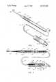
- FIG. 1is a perspective view of the handtool, optical fiber and connector forming the endocoagulator apparatus of the present invention.
- FIG. 2is a longitudinal cross-sectional view of the handtool and connector taken along line 2--2 of FIG. 1.
- the laser endocoagulator apparatus of the present inventionis generally designated at 10.
- the apparatus 10includes an elongated, generally pencil-like handtool which is generally designated at 12, a length of optical fiber generally designated at 14 which is connected at one end to the handtool 12, and which is connected at the other end to a cylindrically shaped connector generally designated at 16.
- the handtoolis tapered to a point at its forward end 18.
- the handtool 12is slightly tapered along its body from the leading end 20 back to the trailing end 22. Also, the leading end 20 of the body is provided with a plurality of annular grooves 21 which facilitate gripping and handling of the handtool with a greater degree of precision and accuracy.
- the slender, tapered, pencil-like shape of handtool 12is specifically designed to meet the needs of ophthalmic surgeons so as to facilitate handling and precision in using the instrument.
- the handtool 12is, in the preferred embodiment, constructed as an integral piece using conventional injection molding techniques or the like.
- Handtool 12is typically made from ABS (acrylonitrile butadiene styrene) plastic material or other similar material so as to be economical, lending to disposability of the handtool after its use.
- ABSacrylonitrile butadiene styrene
- the handtool 12is constructed from a plastic material which has a generally grey, flat, dull finish. Since ophthalmic surgeons typically must operate in the environment of an almost totally dark operating room, it is desirable to avoid using instruments which are light colored or which may be highly reflective and which might thus detract from the field of surgery.
- a stainless steel, medical grade probe in the form of a thin, elongated tube 24is anchored to the tip 18 of handtool 12. As hereinafter more fully described, probe 24 carries inside of it the optical fiber through which the laser beam is transmitted. Typically, the probe 24 is inserted into the interior regions of the eye through a small incision.
- the optical fiber generally designated at 14includes a small quartz fiber 26 through which the laser beam is optically transmitted to the leading tip 25 of the metal probe 24.
- the leading end of the quartz fiber 26is inserted through the probe 24 to a point just slightly beyond the tip of the probe 24.
- the end of the quartz fiberis then polished to remove debris such as excess adhesive or the like which may be attached to the tip of the quartz fiber 26 during assembly procedures. Since the quartz fiber 26 is typically very small (on the order of 400 microns), except for its leading end the quartz fiber 26 is encased in a silicon sheath 28 which enhances the optical transmission properties of fiber 26, and which also lends structural support to the quartz fiber 26 and protects it from being damaged.
- an additional layer(not shown) of Tefzel (TM) may be used to give further strength to the quartz fiber 26.
- the silicon clad quartz fiberis commonly referred to as a "dressed optical fiber,” and is commercially available from one of several companies.
- the dressed optical fiberis a black fiber which is advantageous for use in the context of ophthalmic surgery because it inhibits transmission of light except at the tip of the probe, which fiber may be obtained from Quartz Products Company of Plainfield, N.J.
- the dressed optical fiber consisting of silicon sheath 28 and quartz fiber 26is further encased in a flexible plastic tube 30 which protects the portion of the fiber which leads from the handtool 12 to the connector 16.
- Tubing 30can be constructed of polyethylene or polypropylene plastic or other suitable material.
- the optical fiber 14is inserted through the interior of the handtool 12 by means of an interior bore 32 which extends through the center of the handtool 12.
- the boreis diametrally enlarged for purposes of receiving the plastic tubing 30, which is bonded or otherwise anchored to trailing end 22 of the handtool 12.
- an annular shoulder 36is formed so as to reduce the diameter of the bore. The annular shoulder 36 defines the farthest point at which the metal probe 24 may be inserted into the tapered end 18 of handtool 12.
- the inside diameter of the metal probe 24 and the reduced diameter defined by annular shoulder 36correspond in size to the outside diameter of the sheath 28 encasing quartz fiber 26, whereas the inside diameter of the bore 32 is sized to accept the outside diameter of the silicon sheath 28 which is used for purposes of encasing the quartz fiber 26.
- the optical fibermay be suitably bonded or otherwise secured inside the bore 32 and metal probe 24.
- the laser endocoagulator of the present inventionis adapted to be connected by means of the connector 16 to a conventional laser source, which, in the preferred embodiment, may be an argon ion type laser manufactured by American Laser Corporation in Salt Lake City, Utah.
- Argon lasersproduce a visible blue-green light having a wavelength in the 488 to 514 nanometer range. This light is easily transmitted through clear aqueous tissue such as the cornea, lens, and vitreous humor of the eye.
- tissue pigmentssuch as melanin and hemoglobin absorb the light omitted by an argon laser very effectively.
- an argon laseris very effective, even more so than a xenon laser, when used for purposes of endocoagulation in ophthalmic surgery.
- the connector 16is configurated as a male fitting which is designed to be received by a corresponding female socket (not shown) provided in the argon laser.
- Connector 16includes a cylindrical body 38 which is constructed of a rigid plastic material so as to be inexpensive and easily manufactured using conventional molding technology.
- the exterior surface of connector 16is provided with a plurality of annular grooves 42 which permit the connector 16 to be securely grasped when inserting or removing the connector 16 from the corresponding socket of the laser.
- the body 38 of connector 16has an enlarged bore 46 formed in one end thereof which in turn communicates with a diametrally reduced bore 44 which extends through the remaining length of the body 38. Bore 44 is adapted to receive the protective tubing 30 which surrounds the optical fiber.
- the quartz fiber 26be precisely aligned with the laser beam which is output from the laser source. Because it is difficult to manufacture plastic connectors within the necessary degree of tolerance required to assure the needed alignment, the current practice in the art is to construct the connectors entirely out of high precision, machined steel components which, in some cases, go so far as to include special lenses or reflecting apparatus to insure focusing of the laser beam onto the exposed tip of the quartz fiber.
- the apparatus of the present inventionseeks to overcome the disadvantages which are inherent in the use of these kinds of expensive and complicated connecting apparatus by providing a connector which is simple and inexpensive in its overall construction, but which does not sacrifice the needed precision in terms of alignment.
- Plug 40is joined to the plastic body 38 of the connector.
- Plug 40is made from stainless steel so that it can be machined within extremely close tolerances, thus insuring precise alignment of the optical fiber positioned in the plug with the laser beam output by the laser.
- materials other than plastic and metalcould be used for the body 38 and plug 40 of connector 16.
- the plug 40out of some types of plastic where the particular type of plastic can be machined or otherwise formed within the necessary tolerance to insure proper alignnce, in which case the body 38 and plug 40 could be formed either as an integral, one-piece connector, or in two pieces as illustrated.
- the dominant considerations in choosing the particular materials for body 38 and plug 40are to select a material, like plastic, which can be used for the body portion so as to minimize expense, thus lending to disposability, and to select a material, like stainless steel, which can be used for the smaller plug portion and which can be machined with great precision to insure proper alignment of the optical fiber with the laser beam.
- plasticand “metal” is not intended to be a limitation on the scope of the invention, but is instead intended to be representative of the foregoing design considerations.
- Plug 40includes an annular extension 48 which is adapted to be received by the diametrally enlarged bore 46 formed in the end of the plastic body 38.
- the tip of plug 40is chamfered as at 56 to facilitate insertion of the plug 40 into the corresponding socket of the laser.
- a through bore 50is formed through the center of the plug 40 along a portion of its length.
- the inside diameter of bore 50corresponds to the outside diameter of the silicon sheath 28 which surrounds the quartz fiber 26.
- the silicon sheath 28is stripped from the end 58 of quartz fiber 26, which then projects through the diametrally reduced bore 52 located in the end portion of plug 40.
- the tip of plug 40also includes a conical recess 54 into which the tip 58 the of quartz fiber 26 extends a short distance so as to be entirely exposed to the laser beam output by the laser source.
- the tip 58 of the optical fiberis preferably recessed slightly within cavity 54 so that it cannot be damaged during storage or handling.
- the length of plug 40is designed such that the end 60 of the plastic body 38 will abut against the female socket into which the plug 40 is inserted.
- the endocoagulator apparatus of the present inventionmay be efficiently and economically constructed largely using plastic materials which may be easily manufactured using conventional molding technology and thus lending to disposability of the entire apparatus after a single use.
- the laser endocoagulator of this inventionadvantageously provides for easier handling and greater precision in using the laser beam for purposes of ophthalmic surgery.
Landscapes
- Physics & Mathematics (AREA)
- Health & Medical Sciences (AREA)
- Life Sciences & Earth Sciences (AREA)
- Surgery (AREA)
- Optics & Photonics (AREA)
- Heart & Thoracic Surgery (AREA)
- Medical Informatics (AREA)
- Nuclear Medicine, Radiotherapy & Molecular Imaging (AREA)
- General Physics & Mathematics (AREA)
- Engineering & Computer Science (AREA)
- Biomedical Technology (AREA)
- Electromagnetism (AREA)
- Otolaryngology (AREA)
- Molecular Biology (AREA)
- Animal Behavior & Ethology (AREA)
- General Health & Medical Sciences (AREA)
- Public Health (AREA)
- Veterinary Medicine (AREA)
- Laser Surgery Devices (AREA)
Abstract
Description
1. The Field of the Invention
The present invention relates to laser apparatus used for purposes of surgery and, more particularly, to a disposable laser endocoagulator apparatus for ophthalmic surgery.
2. The Prior Art
The advent of the laser has opened new frontiers to many areas of science and has revolutionized many procedures. One of the most important of these new frontiers has been the application of laser technology to various procedures in the field of medicine. Because lasers can be focused onto very small areas, it is possible to be very precise and to treat specific pathologies without affecting surrounding tissue.
The first significant medical use of a laser occurred in 1965 when doctors utilized a laser to repair a detached retina. The surgeons were able to focus the laser into the interior portion of the eyeball and "weld" the detached retina back into place. At the point where the laser beam struck the retina, the light energy was converted into heat energy which produced a coagulum. During the next few weeks, this coagulum was converted to scar tissue which anchored the retina in place. Since that time, the procedure has been much improved and the utilization of lasers has become a generally accepted method of repair in this type of abnormality. Surgical laser apparatus has also been used to repair retinal tears and abnormal blood vessels within the eye.
Notwithstanding the substantial advances in ophthalmic surgery which have come about as a result of the improvements in laser technology, the current state of the art leaves much to be desired. For example, in the past it has been common practice to use xenon lasers for purposes of ophthalmic surgery. The laser beam from a xenon laser has a tendency to scatter to a certain degree, thus losing some of its intensity and precision. Because of this tendency, the tip of the optical fiber through which the laser beam passes must almost be in contact with the eye tissue which is being treated. Since ophthalmic surgery is typically conducted in the dark so that only the area of the eye on which the surgery is occurring is illuminated, this increases the possibility of causing additional damage to the eye because the surgeon, in attempting to place the tip of the optical fiber so that it is almost in contact with the eye tissue, may accidentally touch the tissue causing a further tear or causing physical damage to surrounding tissue.
The laser endocoagulators used for ophthalmic surgery have typically been rather complicated in their structure. For example, typically the handtool of a laser endocoagulator is quite expensive in its construction because it is made entirely from stainless steel. Thus, the practice in the art has been to resterilize the entire endocoagulator so that it can be reused time after time. However, not only are such resterilization techniques time consuming and expensive in terms of additional labor and handling, but it also renders it more difficult to maintain the delicate optical fiber of the endocoagulator in top condition. For example, it is important that the end of the optical fiber be polished and free from debris so that the laser beam will be transmitted without interference. Any irregularity in the tip of the optical fiber may cause a portion of the light to be absorbed, thus decreasing the amount of the light transmitted causing the tip of the fiber to become overheated, as well as degrading the quality of the laser beam omitted from the tip of the fiber.
Additionally, the connectors utilized to attach the optical fiber to the laser source have generally consisted of a number of very carefully machined metal parts adapted to fit together with great precision so as to accurately align the optical fiber with the laser beam. If the laser beam is not properly aligned with the end of the optical fiber, much of its power can be lost. Additionally, the misdirected beam can vaporize portions of the connector, thus destroying it or creating debris which can obscure the end of the fiber.
Some of the connectors used in the prior art have incorporated a series of lenses to focus the laser beam onto the end of the optical fiber. Many prior art type connectors also incorporate a convex, gold collar disposed about the end of the optical fiber so as to provide an inert reflective surface for the laser beam in the event that it is not precisely aligned with the end of the optical fiber.
While these prior art connectors have proven effective, they are disadvantageous for several reasons. First, such connectors are very expensive to manufacture because of the number of parts that must be carefully machined so as to fit together within extremely close tolerances. While this disadvantage is partially offset by the fact that the connectors are reusable, this creates a second problem. The optical fiber held between the probe and the connector is typically in need of repair or replacement after only a few surgical operations. Because of the need for extremely precise positioning of the optical fiber within the endocoagulator and its connector, it has heretofore been necessary to send the entire assembly back to the factory for repair or replacement. Since the time required for these repairs is generally several weeks, it has proven necessary for hospitals performing large numbers of ophthalmic operations to have many endocoagulator assemblies in their inventory. This requires a large capital outlay and significant inventory cost.
Another problem associated with prior art laser endocoagulators is the need to insure that they are absolutely sterile before reuse. Inasmuch as the tip of the probe is inserted within the eye, extreme care must be taken to insure that the probe is completely sterile to prevent the introduction of bacteria.
Thus, what is needed in the art is a laser endocoagulator apparatus which is very simple in its construction and which is economical to manufacture so that it can be easily disposed of after a single use, and which effectively overcomes the disadvantages of the prior art type endocoagulators mentioned above.
It is a primary object of the present invention to provide a laser endocoagulator apparatus which is relatively simple in its construction and which is inexpensive to manufacture so that it can be utilized once and discarded.
It is a further object of this invention to provide a laser endocoagulator apparatus which includes a simple and inexpensive connector which insures that the optical fiber is precisely aligned with the output of the laser source.
Another object of the present invention is to provide an endocoagulator apparatus for use with an argon ion laser so as to provide greater precision in the use of the laser beam.
These and other objects and features of the present invention will become more fully apparent from the following description and appended claims taken in conjunction with the accompanying drawings.
In accordance with the foregoing objects, the present invention provides a novel laser endocoagulator apparatus suitable for use in ophthalmic surgery. The entire apparatus is inexpensive to manufacture and thus disposable.
In the presently preferred embodiment, the laser endocoagulator apparatus of the present invention includes an elongated handtool constructed of plastic. The end of the handtool is slightly tapered and a stainless steel probe projects from the end thereof. A silicon clad optical fiber passes through the center of the handtool and the fiber terminates at the end of the probe. A series of circular grooves are formed on the forward portion of the handtool to facilitate its handling. A two-piece disposable connector is attached to the other end of the optical fiber for attaching the fiber to a laser source. The connector includes a cylindrical plastic body having a bore passing through the center thereof into which the optical fiber is anchored. A small metal plug, machined to the necessary tolerance, is positioned in the terminal end of the plastic body for precisely aligning the tip of the optical fiber with the output of the laser source.
Reference is next made to the drawings, in which like parts are designated with like numerals throughout, and in which:
FIG. 1 is a perspective view of the handtool, optical fiber and connector forming the endocoagulator apparatus of the present invention; and
FIG. 2 is a longitudinal cross-sectional view of the handtool and connector taken alongline 2--2 of FIG. 1.
Referring first to FIG. 1, the laser endocoagulator apparatus of the present invention is generally designated at 10. Theapparatus 10 includes an elongated, generally pencil-like handtool which is generally designated at 12, a length of optical fiber generally designated at 14 which is connected at one end to thehandtool 12, and which is connected at the other end to a cylindrically shaped connector generally designated at 16. The handtool is tapered to a point at itsforward end 18.
On performing ophthalmic surgery, it is of utmost importance to exercise great care so as to insure precision and accuracy in inserting and positioning the probe within the interior regions of the eye. Thus, thehandtool 12 is slightly tapered along its body from the leadingend 20 back to thetrailing end 22. Also, the leadingend 20 of the body is provided with a plurality ofannular grooves 21 which facilitate gripping and handling of the handtool with a greater degree of precision and accuracy. The slender, tapered, pencil-like shape ofhandtool 12 is specifically designed to meet the needs of ophthalmic surgeons so as to facilitate handling and precision in using the instrument.
Thehandtool 12 is, in the preferred embodiment, constructed as an integral piece using conventional injection molding techniques or the like.Handtool 12 is typically made from ABS (acrylonitrile butadiene styrene) plastic material or other similar material so as to be economical, lending to disposability of the handtool after its use. Also, in the preferred embodiment thehandtool 12 is constructed from a plastic material which has a generally grey, flat, dull finish. Since ophthalmic surgeons typically must operate in the environment of an almost totally dark operating room, it is desirable to avoid using instruments which are light colored or which may be highly reflective and which might thus detract from the field of surgery.
A stainless steel, medical grade probe in the form of a thin,elongated tube 24 is anchored to thetip 18 ofhandtool 12. As hereinafter more fully described, probe 24 carries inside of it the optical fiber through which the laser beam is transmitted. Typically, theprobe 24 is inserted into the interior regions of the eye through a small incision.
With reference next to FIG. 2, it will be seen that the optical fiber generally designated at 14 includes asmall quartz fiber 26 through which the laser beam is optically transmitted to the leadingtip 25 of themetal probe 24. The leading end of thequartz fiber 26 is inserted through theprobe 24 to a point just slightly beyond the tip of theprobe 24. The end of the quartz fiber is then polished to remove debris such as excess adhesive or the like which may be attached to the tip of thequartz fiber 26 during assembly procedures. Since thequartz fiber 26 is typically very small (on the order of 400 microns), except for its leading end thequartz fiber 26 is encased in asilicon sheath 28 which enhances the optical transmission properties offiber 26, and which also lends structural support to thequartz fiber 26 and protects it from being damaged. In some cases, an additional layer (not shown) of Tefzel (TM) may be used to give further strength to thequartz fiber 26. The silicon clad quartz fiber is commonly referred to as a "dressed optical fiber," and is commercially available from one of several companies. For example, in the illustrated embodiment the dressed optical fiber is a black fiber which is advantageous for use in the context of ophthalmic surgery because it inhibits transmission of light except at the tip of the probe, which fiber may be obtained from Quartz Products Company of Plainfield, N.J.
The dressed optical fiber consisting ofsilicon sheath 28 andquartz fiber 26 is further encased in a flexibleplastic tube 30 which protects the portion of the fiber which leads from thehandtool 12 to theconnector 16.Tubing 30 can be constructed of polyethylene or polypropylene plastic or other suitable material.
As shown best in FIG. 2, theoptical fiber 14 is inserted through the interior of thehandtool 12 by means of aninterior bore 32 which extends through the center of thehandtool 12. At oneend 34 the bore is diametrally enlarged for purposes of receiving theplastic tubing 30, which is bonded or otherwise anchored to trailingend 22 of thehandtool 12. At the other end ofbore 32, anannular shoulder 36 is formed so as to reduce the diameter of the bore. Theannular shoulder 36 defines the farthest point at which themetal probe 24 may be inserted into thetapered end 18 ofhandtool 12. The inside diameter of themetal probe 24 and the reduced diameter defined byannular shoulder 36 correspond in size to the outside diameter of thesheath 28 encasingquartz fiber 26, whereas the inside diameter of thebore 32 is sized to accept the outside diameter of thesilicon sheath 28 which is used for purposes of encasing thequartz fiber 26. The optical fiber may be suitably bonded or otherwise secured inside thebore 32 andmetal probe 24.
As schematically illustrated in FIG. 2, the laser endocoagulator of the present invention is adapted to be connected by means of theconnector 16 to a conventional laser source, which, in the preferred embodiment, may be an argon ion type laser manufactured by American Laser Corporation in Salt Lake City, Utah. Argon lasers produce a visible blue-green light having a wavelength in the 488 to 514 nanometer range. This light is easily transmitted through clear aqueous tissue such as the cornea, lens, and vitreous humor of the eye. On the other hand, certain tissue pigments such as melanin and hemoglobin absorb the light omitted by an argon laser very effectively. Thus, an argon laser is very effective, even more so than a xenon laser, when used for purposes of endocoagulation in ophthalmic surgery.
Theconnector 16 is configurated as a male fitting which is designed to be received by a corresponding female socket (not shown) provided in the argon laser.Connector 16 includes acylindrical body 38 which is constructed of a rigid plastic material so as to be inexpensive and easily manufactured using conventional molding technology. The exterior surface ofconnector 16 is provided with a plurality ofannular grooves 42 which permit theconnector 16 to be securely grasped when inserting or removing theconnector 16 from the corresponding socket of the laser.
As illustrated in FIG. 2, thebody 38 ofconnector 16 has anenlarged bore 46 formed in one end thereof which in turn communicates with a diametrally reduced bore 44 which extends through the remaining length of thebody 38.Bore 44 is adapted to receive theprotective tubing 30 which surrounds the optical fiber.
As mentioned above, it is essential that thequartz fiber 26 be precisely aligned with the laser beam which is output from the laser source. Because it is difficult to manufacture plastic connectors within the necessary degree of tolerance required to assure the needed alignment, the current practice in the art is to construct the connectors entirely out of high precision, machined steel components which, in some cases, go so far as to include special lenses or reflecting apparatus to insure focusing of the laser beam onto the exposed tip of the quartz fiber. The apparatus of the present invention seeks to overcome the disadvantages which are inherent in the use of these kinds of expensive and complicated connecting apparatus by providing a connector which is simple and inexpensive in its overall construction, but which does not sacrifice the needed precision in terms of alignment.
As shown in FIG. 2, asmall metal plug 40 is joined to theplastic body 38 of the connector.Plug 40 is made from stainless steel so that it can be machined within extremely close tolerances, thus insuring precise alignment of the optical fiber positioned in the plug with the laser beam output by the laser.
Obviously, materials other than plastic and metal could be used for thebody 38 and plug 40 ofconnector 16. For example, it may be possible to form theplug 40 out of some types of plastic where the particular type of plastic can be machined or otherwise formed within the necessary tolerance to insure proper alignmment, in which case thebody 38 and plug 40 could be formed either as an integral, one-piece connector, or in two pieces as illustrated. The dominant considerations in choosing the particular materials forbody 38 and plug 40 are to select a material, like plastic, which can be used for the body portion so as to minimize expense, thus lending to disposability, and to select a material, like stainless steel, which can be used for the smaller plug portion and which can be machined with great precision to insure proper alignment of the optical fiber with the laser beam. Thus, use of the terms "plastic" and "metal" is not intended to be a limitation on the scope of the invention, but is instead intended to be representative of the foregoing design considerations.
The tip ofplug 40 also includes aconical recess 54 into which thetip 58 the ofquartz fiber 26 extends a short distance so as to be entirely exposed to the laser beam output by the laser source. Thetip 58 of the optical fiber is preferably recessed slightly withincavity 54 so that it cannot be damaged during storage or handling. The length ofplug 40 is designed such that theend 60 of theplastic body 38 will abut against the female socket into which theplug 40 is inserted.
In summary, from the foregoing description and drawings it will be appreciated that the endocoagulator apparatus of the present invention may be efficiently and economically constructed largely using plastic materials which may be easily manufactured using conventional molding technology and thus lending to disposability of the entire apparatus after a single use. The laser endocoagulator of this invention advantageously provides for easier handling and greater precision in using the laser beam for purposes of ophthalmic surgery.
Although the present invention has been described with reference to its presently preferred embodiment, the invention may be embodied in other specific forms without departing from the spirit or essential characteristics thereof. The described embodiment is to be considered in all respects only as illustrative and not restrictive, and the scope of the invention is, therefore, indicated by the appended claims rather than by the foregoing description. All modifications or changes which come within the meaning and range of equivalency of the claims are to be embraced within their scope.
Claims (2)
1. A disposable endocoagulator apparatus adapted for connection to an argon laser having a female receptacle providing a laser output suited to optical fiber transmission for ophthalmic surgery and like procedures, comprising:
(a) an elongated, cylindrical-shaped handtool formed as a integral, plastic molded structure having:
(i) a cylindrical, pencil-like body having a leading end and a trailing end;
(ii) a tip portion formed integral with said body leading end and tapered towards the leading end of said body;
(iii) a central bore extending through the length of said handtool body and tip portion;
(iv) within said tip portion a first enlarged bore concentric with said central bore for mounting a probe;
(v) within the trailing end of said body a second enlarged bore concentric with said central bore for receiving a first optical fiber sheath; and
(vi) within said body an annular shoulder surrounding and concentric with said central bore and extending within said body between said shoulder and said second enlarged bore a third enlarged bore substantially equal in size to the size of said first enlarged bore and concentric with said central bore for receiving a second optical fiber sheath;
(b) a hollow, elongated, stainless steel tube forming a laser probe, said probe having a minor portion of the length thereof anchored in said tip portion first enlarged bore and having a major portion of the length thereof extending outwardly from said tip portion to a leading end, the axis of said probe being aligned with the axis of said handtool;
(c) a fiber optics connector assembly comprising:
(i) an elongated, cylindrical-shaped, integral, plastic-molded body member having a leading end and a trailing end and having a central bore through the length thereof and a fourth enlarged bore at the trailing end thereof concentric with said body member central bore, said body member having a flat annular surface at the trailing end thereof surrounding said body member fourth enlarged bore; and
(ii) a cylindrical, precisely-formed, male plug member having a leading end and a trailing end and positioned at the trailing end of and forming an integral connector structure with said body member, said plug member having a cylindrical portion of reduced diameter at its leading end and being secured to said body member by said plug member leading end of reduced diameter being inserted and secured in said body member fourth enlarged bore, the trailing end of said plug member being tapered for guiding said male plug member into said female receptacle, said plug member having a bore aligned with and forming a continuation of the central bore of said body member and at the trailing end of said plug member an inwardly tapered recess around the plug member bore, the diameter and length of said male plug member being adapted for precise alignment and positioning within a mating argon laser female receptacle having an output source oriented along an axis aligned with the axis of said male plug member when inserted in said female receptacle, said flat annular surface serving as a stop for controlling the depth of said plug member in said receptacle; and
(d) a single, continuous length of optical fiber, said optical fiber having:
(i) a leading portion extending from a leading polished end surface positioned slightly outwardly from the leading end of said probe and extending through said probe and handtool bore;
(ii) an intermediate portion extending from the trailing end of said handtool to said connector assembly;
(iii) a trailing end portion extending through said connector assembly body member central bore and said plug member bore and terminating with a trailing end surface disposed slightly within said plug member recess;
(iv) a first cladding sheath extending over said length of optical fiber from a location slightly behind the leading polished end thereof to a location within said plug member and forwardly of said recess; and
(v) a second plastic sheath anchored in said connector assembly body member central bore at one end and surrounding said optical fiber and extending to and anchored in said second enlarged bore at the trailing end of said handtool.
2. A disposable endocoagulator apparatus as claimed in claim 1 wherein said plug member is formed of a precision machined metal.
Priority Applications (1)
| Application Number | Priority Date | Filing Date | Title |
|---|---|---|---|
| US06/437,288US4537193A (en) | 1982-10-28 | 1982-10-28 | Laser endocoagulator apparatus |
Applications Claiming Priority (1)
| Application Number | Priority Date | Filing Date | Title |
|---|---|---|---|
| US06/437,288US4537193A (en) | 1982-10-28 | 1982-10-28 | Laser endocoagulator apparatus |
Publications (1)
| Publication Number | Publication Date |
|---|---|
| US4537193Atrue US4537193A (en) | 1985-08-27 |
Family
ID=23735834
Family Applications (1)
| Application Number | Title | Priority Date | Filing Date |
|---|---|---|---|
| US06/437,288Expired - LifetimeUS4537193A (en) | 1982-10-28 | 1982-10-28 | Laser endocoagulator apparatus |
Country Status (1)
| Country | Link |
|---|---|
| US (1) | US4537193A (en) |
Cited By (77)
| Publication number | Priority date | Publication date | Assignee | Title |
|---|---|---|---|---|
| US4633872A (en)* | 1983-11-08 | 1987-01-06 | Hgm, Incorporated | Laser optical delivery apparatus |
| EP0168261A3 (en)* | 1984-07-13 | 1987-01-14 | Dainichi-Nippon Cables, Ltd. | Connector for high energy beam |
| US4694828A (en)* | 1986-04-21 | 1987-09-22 | Eichenbaum Daniel M | Laser system for intraocular tissue removal |
| US4735201A (en)* | 1986-01-30 | 1988-04-05 | The Beth Israel Hospital Association | Optical fiber with detachable metallic tip for intravascular laser coagulation of arteries, veins, aneurysms, vascular malformations and arteriovenous fistulas |
| US4744624A (en)* | 1985-07-04 | 1988-05-17 | Pilkington, Medical Systems, Ltd. | Optical fibre assembly for transmitting high energy laser radiation |
| US4756597A (en)* | 1985-11-08 | 1988-07-12 | Messerschmitt-Bolkow-Blohm Gmbh | Light guide, in particular for medical instruments |
| US4785805A (en)* | 1985-05-28 | 1988-11-22 | Surgical Laser Technologies, Inc. | Two-piece disposable laser delivery system |
| EP0336009A1 (en)* | 1988-03-07 | 1989-10-11 | Deutsche Aerospace AG | Single light conductor device |
| US4873969A (en)* | 1987-12-11 | 1989-10-17 | Huebsch Donald L | Method and apparatus for removal of bone cement |
| US4895145A (en)* | 1985-05-28 | 1990-01-23 | Surgical Laser Technologies, Inc. | Two-piece disposable laser delivery system |
| US5029581A (en)* | 1986-11-19 | 1991-07-09 | Fuji Electric Co., Ltd. | Laser therapeutic apparatus |
| US5037421A (en)* | 1989-10-06 | 1991-08-06 | Coherent, Inc., Medical Group | Mid-infrared laser arthroscopic procedure |
| USD320856S (en) | 1989-01-04 | 1991-10-15 | Surgical Technologies Inc. | Bipolar pen coagulator |
| US5078712A (en)* | 1989-10-24 | 1992-01-07 | Surgical Technologies, Inc. | Tissue manipulator for use in vitreous surgery combining a fiber optic endoilluminator and membrane pic |
| US5116329A (en)* | 1988-10-20 | 1992-05-26 | Pfizer Hospital Products Groups, Inc. | Medical laser interconnect system |
| US5139494A (en)* | 1988-11-10 | 1992-08-18 | Premier Laser Systems, Inc. | Multiwavelength medical laser method |
| US5147354A (en)* | 1988-08-19 | 1992-09-15 | Coherent, Inc. | Mid-infrared laser endoscope |
| US5179610A (en)* | 1991-04-19 | 1993-01-12 | Trimedyne, Inc. | Connector for coupling of laser energy |
| US5201730A (en)* | 1989-10-24 | 1993-04-13 | Surgical Technologies, Inc. | Tissue manipulator for use in vitreous surgery combining a fiber optic endoilluminator with an infusion/aspiration system |
| US5203353A (en)* | 1989-10-24 | 1993-04-20 | Surgical Technologies, Inc. | Method of penetrating and working in the vitreous humor of the eye |
| US5207673A (en)* | 1989-06-09 | 1993-05-04 | Premier Laser Systems, Inc. | Fiber optic apparatus for use with medical lasers |
| USD341200S (en) | 1992-12-28 | 1993-11-09 | Coherent, Inc. | Fiber optic handpiece |
| US5282798A (en)* | 1992-02-12 | 1994-02-01 | Heraeus Surgical, Inc. | Apparatus for supporting an orbicularly tipped surgical laser fiber |
| US5290272A (en)* | 1992-03-16 | 1994-03-01 | Helios Inc. | Method for the joining of ocular tissues using laser light |
| US5300061A (en)* | 1991-08-29 | 1994-04-05 | Surgical Technologies, Inc. | Laser delivery probe having a mechanically free floating sheath |
| US5314435A (en)* | 1992-05-19 | 1994-05-24 | United States Surgical Corporation | Anvil delivery system |
| US5344059A (en)* | 1992-05-19 | 1994-09-06 | United States Surgical Corporation | Surgical apparatus and anvil delivery system therefor |
| US5374265A (en)* | 1985-09-27 | 1994-12-20 | Laser Biotech, Inc. | Collagen treatment apparatus and method |
| USD358208S (en) | 1993-03-23 | 1995-05-09 | William H. McMahan | Medical laser handpiece |
| US5441496A (en)* | 1993-04-15 | 1995-08-15 | Infinitech, Inc. | Laser delivery system with soft tip |
| US5454807A (en)* | 1993-05-14 | 1995-10-03 | Boston Scientific Corporation | Medical treatment of deeply seated tissue using optical radiation |
| US5478338A (en)* | 1993-09-24 | 1995-12-26 | Reynard; Michael | Fiber optic sleeve for surgical instruments |
| US5484432A (en)* | 1985-09-27 | 1996-01-16 | Laser Biotech, Inc. | Collagen treatment apparatus |
| US5497440A (en)* | 1993-06-08 | 1996-03-05 | Ramot University Authority For Applied Research & Industrial Development Ltd. | Laser beam waveguide and laser beam delivery system including same |
| US5588579A (en)* | 1994-08-25 | 1996-12-31 | United States Surgical Corporation | Anvil for circular stapler |
| US5738677A (en)* | 1992-04-10 | 1998-04-14 | Premier Laser Systems, Inc. | Apparatus and method for performing eye surgery |
| US5785645A (en)* | 1996-04-16 | 1998-07-28 | Synergetics, Inc. | Beveled tip illuminator for microsurgery |
| US5807242A (en)* | 1997-03-24 | 1998-09-15 | Synergetics, Inc. | Microsurgical laser probe with homogeneous laser light field |
| US5843071A (en)* | 1986-12-18 | 1998-12-01 | Bath; Patricia E. | Method and apparatus for ablating and removing cataract lenses |
| WO2001026543A1 (en)* | 1999-10-13 | 2001-04-19 | C.R. Bard, Inc. | Connector for optical fiber tissue localization device |
| WO2001026542A1 (en)* | 1999-10-13 | 2001-04-19 | C.R. Bard, Inc. | Optical fiber tissue localization device |
| US6575989B1 (en) | 1999-09-13 | 2003-06-10 | Synergetics, Inc. | Adjustable stiffness membrane scraper |
| US20040161221A1 (en)* | 2003-02-13 | 2004-08-19 | Kawasaki Jukogyo Kabushiki Kaisha | Optical fiber probe |
| USD501047S1 (en) | 2003-09-11 | 2005-01-18 | Deroyal Industries, Inc. | Cautery device |
| US20050059967A1 (en)* | 2003-09-11 | 2005-03-17 | Breazeale Earl E. | Electrosurgical device |
| US20060041291A1 (en)* | 2004-08-16 | 2006-02-23 | Buzawa David M | Directional probe treatment apparatus |
| US20060253112A1 (en)* | 2005-05-05 | 2006-11-09 | Ceramoptec Industries, Inc. | Cosmetic laser treatment device and method for localized lipodystrophies and flaccidity |
| US20080188835A1 (en)* | 2005-05-18 | 2008-08-07 | Cooltouch Incorporated | Treatment of cellulite and adipose tissue with mid-infrared radiation |
| US20080306476A1 (en)* | 2005-05-18 | 2008-12-11 | Cooltouch Incorporated | Thermally mediated tissue molding |
| USD585937S1 (en)* | 2006-12-06 | 2009-02-03 | Parker Pen Products | Writing instrument |
| US20090082785A1 (en)* | 2007-09-24 | 2009-03-26 | Milliman Keith L | Anvil Delivery Device Accessory |
| KR100914142B1 (en) | 2009-01-16 | 2009-08-28 | 주식회사 루트로닉 | Optical fiber assembly for medical laser surgery |
| DE112007002632T5 (en) | 2006-11-03 | 2009-12-31 | Iridex Corp., Mountain View | Illuminated laser probe treatment device with molded tip |
| US7655002B2 (en) | 1996-03-21 | 2010-02-02 | Second Sight Laser Technologies, Inc. | Lenticular refractive surgery of presbyopia, other refractive errors, and cataract retardation |
| US8262646B2 (en) | 2006-01-20 | 2012-09-11 | Lensar, Inc. | System and method for providing the shaped structural weakening of the human lens with a laser |
| US8382745B2 (en) | 2009-07-24 | 2013-02-26 | Lensar, Inc. | Laser system and method for astigmatic corrections in association with cataract treatment |
| US8465478B2 (en) | 2009-07-24 | 2013-06-18 | Lensar, Inc. | System and method for performing LADAR assisted procedures on the lens of an eye |
| US8480659B2 (en) | 2008-07-25 | 2013-07-09 | Lensar, Inc. | Method and system for removal and replacement of lens material from the lens of an eye |
| US8500723B2 (en) | 2008-07-25 | 2013-08-06 | Lensar, Inc. | Liquid filled index matching device for ophthalmic laser procedures |
| US8556425B2 (en) | 2010-02-01 | 2013-10-15 | Lensar, Inc. | Purkinjie image-based alignment of suction ring in ophthalmic applications |
| USD694890S1 (en) | 2010-10-15 | 2013-12-03 | Lensar, Inc. | Laser system for treatment of the eye |
| USD695408S1 (en) | 2010-10-15 | 2013-12-10 | Lensar, Inc. | Laser system for treatment of the eye |
| US8617146B2 (en) | 2009-07-24 | 2013-12-31 | Lensar, Inc. | Laser system and method for correction of induced astigmatism |
| US20140112358A1 (en)* | 2011-06-04 | 2014-04-24 | Roland Berger | Excitation unti fir a fiber laser |
| US8758332B2 (en) | 2009-07-24 | 2014-06-24 | Lensar, Inc. | Laser system and method for performing and sealing corneal incisions in the eye |
| US8801186B2 (en) | 2010-10-15 | 2014-08-12 | Lensar, Inc. | System and method of scan controlled illumination of structures within an eye |
| US9180051B2 (en) | 2006-01-20 | 2015-11-10 | Lensar Inc. | System and apparatus for treating the lens of an eye |
| US9375349B2 (en) | 2006-01-20 | 2016-06-28 | Lensar, Llc | System and method for providing laser shot patterns to the lens of an eye |
| US9393154B2 (en) | 2011-10-28 | 2016-07-19 | Raymond I Myers | Laser methods for creating an antioxidant sink in the crystalline lens for the maintenance of eye health and physiology and slowing presbyopia development |
| US9545338B2 (en) | 2006-01-20 | 2017-01-17 | Lensar, Llc. | System and method for improving the accommodative amplitude and increasing the refractive power of the human lens with a laser |
| US9655626B2 (en) | 2014-04-28 | 2017-05-23 | Covidien Lp | Anvil assembly delivery system |
| US20180078410A1 (en)* | 2016-09-20 | 2018-03-22 | Cosmin-Adrian Gavanescu | Surgery Device |
| US10226167B2 (en) | 2010-05-13 | 2019-03-12 | Beaver-Visitec International, Inc. | Laser video endoscope |
| USD914211S1 (en)* | 2019-08-18 | 2021-03-23 | Gregorio Hernandez Zendejas | Electrosurgical device |
| USD950727S1 (en)* | 2019-09-04 | 2022-05-03 | Baylis Medical Company Inc. | Medical device with a curve with a proximal curve indicator |
| US11337598B2 (en) | 2010-05-13 | 2022-05-24 | Beaver-Visitec International, Inc. | Laser video endoscope |
| USD972726S1 (en)* | 2021-01-11 | 2022-12-13 | Pursuit of Madness LLC | Tattoo device |
Citations (18)
| Publication number | Priority date | Publication date | Assignee | Title |
|---|---|---|---|---|
| US3383491A (en)* | 1964-05-05 | 1968-05-14 | Hrand M. Muncheryan | Laser welding machine |
| US3471215A (en)* | 1965-07-16 | 1969-10-07 | American Optical Corp | Fiber laser device provided with long flexible energy-directing probe-like structure |
| US3538919A (en)* | 1967-04-07 | 1970-11-10 | Gregory System Inc | Depilation by means of laser energy |
| US3693623A (en)* | 1970-12-25 | 1972-09-26 | Gregory System Inc | Photocoagulation means and method for depilation |
| US3746814A (en)* | 1971-12-20 | 1973-07-17 | Sybron Corp | Finger actuated surgical electrode holder |
| US3821510A (en)* | 1973-02-22 | 1974-06-28 | H Muncheryan | Hand held laser instrumentation device |
| US3825004A (en)* | 1972-09-13 | 1974-07-23 | Durden Enterprises Ltd | Disposable electrosurgical cautery |
| US3834391A (en)* | 1973-01-19 | 1974-09-10 | Block Carol Ltd | Method and apparatus for photoepilation |
| US3865113A (en)* | 1972-10-17 | 1975-02-11 | Laser Ind Ltd | Laser device particularly useful as surgical scalpel |
| US3910278A (en)* | 1974-06-03 | 1975-10-07 | Dynatech Corp | Cryosurgical probe |
| US3982541A (en)* | 1974-07-29 | 1976-09-28 | Esperance Jr Francis A L | Eye surgical instrument |
| US4034761A (en)* | 1975-12-15 | 1977-07-12 | The Birtcher Corporation | Disposable electrosurgical switching assembly |
| US4126136A (en)* | 1976-02-09 | 1978-11-21 | Research Corporation | Photocoagulating scalpel system |
| DE2740969A1 (en)* | 1977-09-12 | 1979-03-22 | Karl Heinz Dr Med Caspers | Laser beam stimulation therapy equipment - has optical fibre bundle in separate parts attached to body at different acupuncture points |
| DE2828322A1 (en)* | 1978-06-28 | 1980-01-10 | Eichler Juergen | Laser instrument for medical use - comprises long thin tube with lens at distal end and includes light conductive fibre |
| US4233493A (en)* | 1974-05-21 | 1980-11-11 | Nath Guenther | Apparatus for applying intense light radiation to a limited area |
| FR2479485A1 (en)* | 1980-04-01 | 1981-10-02 | Asahi Optical Co Ltd | FIBER RETENTION DEVICE FOR POWER LASER |
| US4316467A (en)* | 1980-06-23 | 1982-02-23 | Lorenzo P. Maun | Control for laser hemangioma treatment system |
- 1982
- 1982-10-28USUS06/437,288patent/US4537193A/ennot_activeExpired - Lifetime
Patent Citations (18)
| Publication number | Priority date | Publication date | Assignee | Title |
|---|---|---|---|---|
| US3383491A (en)* | 1964-05-05 | 1968-05-14 | Hrand M. Muncheryan | Laser welding machine |
| US3471215A (en)* | 1965-07-16 | 1969-10-07 | American Optical Corp | Fiber laser device provided with long flexible energy-directing probe-like structure |
| US3538919A (en)* | 1967-04-07 | 1970-11-10 | Gregory System Inc | Depilation by means of laser energy |
| US3693623A (en)* | 1970-12-25 | 1972-09-26 | Gregory System Inc | Photocoagulation means and method for depilation |
| US3746814A (en)* | 1971-12-20 | 1973-07-17 | Sybron Corp | Finger actuated surgical electrode holder |
| US3825004A (en)* | 1972-09-13 | 1974-07-23 | Durden Enterprises Ltd | Disposable electrosurgical cautery |
| US3865113A (en)* | 1972-10-17 | 1975-02-11 | Laser Ind Ltd | Laser device particularly useful as surgical scalpel |
| US3834391A (en)* | 1973-01-19 | 1974-09-10 | Block Carol Ltd | Method and apparatus for photoepilation |
| US3821510A (en)* | 1973-02-22 | 1974-06-28 | H Muncheryan | Hand held laser instrumentation device |
| US4233493A (en)* | 1974-05-21 | 1980-11-11 | Nath Guenther | Apparatus for applying intense light radiation to a limited area |
| US3910278A (en)* | 1974-06-03 | 1975-10-07 | Dynatech Corp | Cryosurgical probe |
| US3982541A (en)* | 1974-07-29 | 1976-09-28 | Esperance Jr Francis A L | Eye surgical instrument |
| US4034761A (en)* | 1975-12-15 | 1977-07-12 | The Birtcher Corporation | Disposable electrosurgical switching assembly |
| US4126136A (en)* | 1976-02-09 | 1978-11-21 | Research Corporation | Photocoagulating scalpel system |
| DE2740969A1 (en)* | 1977-09-12 | 1979-03-22 | Karl Heinz Dr Med Caspers | Laser beam stimulation therapy equipment - has optical fibre bundle in separate parts attached to body at different acupuncture points |
| DE2828322A1 (en)* | 1978-06-28 | 1980-01-10 | Eichler Juergen | Laser instrument for medical use - comprises long thin tube with lens at distal end and includes light conductive fibre |
| FR2479485A1 (en)* | 1980-04-01 | 1981-10-02 | Asahi Optical Co Ltd | FIBER RETENTION DEVICE FOR POWER LASER |
| US4316467A (en)* | 1980-06-23 | 1982-02-23 | Lorenzo P. Maun | Control for laser hemangioma treatment system |
Non-Patent Citations (2)
| Title |
|---|
| Smith et al., "New Trends in CO2 Laser Micro. . . .", SPIE, vol. 236, 1980, pp. 173-182. |
| Smith et al., New Trends in CO 2 Laser Micro. . . . , SPIE, vol. 236, 1980, pp. 173 182.* |
Cited By (99)
| Publication number | Priority date | Publication date | Assignee | Title |
|---|---|---|---|---|
| US4633872A (en)* | 1983-11-08 | 1987-01-06 | Hgm, Incorporated | Laser optical delivery apparatus |
| EP0168261A3 (en)* | 1984-07-13 | 1987-01-14 | Dainichi-Nippon Cables, Ltd. | Connector for high energy beam |
| US4737011A (en)* | 1984-07-13 | 1988-04-12 | Dainichi-Nippon Cables Ltd. | Connector for high energy beam |
| US4785805A (en)* | 1985-05-28 | 1988-11-22 | Surgical Laser Technologies, Inc. | Two-piece disposable laser delivery system |
| US4895145A (en)* | 1985-05-28 | 1990-01-23 | Surgical Laser Technologies, Inc. | Two-piece disposable laser delivery system |
| US4744624A (en)* | 1985-07-04 | 1988-05-17 | Pilkington, Medical Systems, Ltd. | Optical fibre assembly for transmitting high energy laser radiation |
| US5618284A (en)* | 1985-09-27 | 1997-04-08 | Sunrise Technologies | Collagen treatment apparatus |
| US5374265A (en)* | 1985-09-27 | 1994-12-20 | Laser Biotech, Inc. | Collagen treatment apparatus and method |
| US5484432A (en)* | 1985-09-27 | 1996-01-16 | Laser Biotech, Inc. | Collagen treatment apparatus |
| US4756597A (en)* | 1985-11-08 | 1988-07-12 | Messerschmitt-Bolkow-Blohm Gmbh | Light guide, in particular for medical instruments |
| US4735201A (en)* | 1986-01-30 | 1988-04-05 | The Beth Israel Hospital Association | Optical fiber with detachable metallic tip for intravascular laser coagulation of arteries, veins, aneurysms, vascular malformations and arteriovenous fistulas |
| US4694828A (en)* | 1986-04-21 | 1987-09-22 | Eichenbaum Daniel M | Laser system for intraocular tissue removal |
| US5029581A (en)* | 1986-11-19 | 1991-07-09 | Fuji Electric Co., Ltd. | Laser therapeutic apparatus |
| US5843071A (en)* | 1986-12-18 | 1998-12-01 | Bath; Patricia E. | Method and apparatus for ablating and removing cataract lenses |
| US4873969A (en)* | 1987-12-11 | 1989-10-17 | Huebsch Donald L | Method and apparatus for removal of bone cement |
| EP0336009A1 (en)* | 1988-03-07 | 1989-10-11 | Deutsche Aerospace AG | Single light conductor device |
| US5147354A (en)* | 1988-08-19 | 1992-09-15 | Coherent, Inc. | Mid-infrared laser endoscope |
| US5116329A (en)* | 1988-10-20 | 1992-05-26 | Pfizer Hospital Products Groups, Inc. | Medical laser interconnect system |
| US5139494A (en)* | 1988-11-10 | 1992-08-18 | Premier Laser Systems, Inc. | Multiwavelength medical laser method |
| US5304167A (en)* | 1988-11-10 | 1994-04-19 | Premier Laser Systems, Inc. | Multiwavelength medical laser method |
| USD320856S (en) | 1989-01-04 | 1991-10-15 | Surgical Technologies Inc. | Bipolar pen coagulator |
| US5207673A (en)* | 1989-06-09 | 1993-05-04 | Premier Laser Systems, Inc. | Fiber optic apparatus for use with medical lasers |
| US5037421A (en)* | 1989-10-06 | 1991-08-06 | Coherent, Inc., Medical Group | Mid-infrared laser arthroscopic procedure |
| US5203353A (en)* | 1989-10-24 | 1993-04-20 | Surgical Technologies, Inc. | Method of penetrating and working in the vitreous humor of the eye |
| US5201730A (en)* | 1989-10-24 | 1993-04-13 | Surgical Technologies, Inc. | Tissue manipulator for use in vitreous surgery combining a fiber optic endoilluminator with an infusion/aspiration system |
| US5078712A (en)* | 1989-10-24 | 1992-01-07 | Surgical Technologies, Inc. | Tissue manipulator for use in vitreous surgery combining a fiber optic endoilluminator and membrane pic |
| US5179610A (en)* | 1991-04-19 | 1993-01-12 | Trimedyne, Inc. | Connector for coupling of laser energy |
| US5300061A (en)* | 1991-08-29 | 1994-04-05 | Surgical Technologies, Inc. | Laser delivery probe having a mechanically free floating sheath |
| US5282798A (en)* | 1992-02-12 | 1994-02-01 | Heraeus Surgical, Inc. | Apparatus for supporting an orbicularly tipped surgical laser fiber |
| US5401271A (en)* | 1992-02-12 | 1995-03-28 | Heraeus Surgical, Inc. | Apparatus for supporting an orbicularly tipped surgical laser fiber |
| US5290272A (en)* | 1992-03-16 | 1994-03-01 | Helios Inc. | Method for the joining of ocular tissues using laser light |
| US5738677A (en)* | 1992-04-10 | 1998-04-14 | Premier Laser Systems, Inc. | Apparatus and method for performing eye surgery |
| US5314435A (en)* | 1992-05-19 | 1994-05-24 | United States Surgical Corporation | Anvil delivery system |
| US6053390A (en)* | 1992-05-19 | 2000-04-25 | United States Surgical | Anvil for surgical stapler |
| US5344059A (en)* | 1992-05-19 | 1994-09-06 | United States Surgical Corporation | Surgical apparatus and anvil delivery system therefor |
| USD341200S (en) | 1992-12-28 | 1993-11-09 | Coherent, Inc. | Fiber optic handpiece |
| USD358208S (en) | 1993-03-23 | 1995-05-09 | William H. McMahan | Medical laser handpiece |
| US5441496A (en)* | 1993-04-15 | 1995-08-15 | Infinitech, Inc. | Laser delivery system with soft tip |
| US5454807A (en)* | 1993-05-14 | 1995-10-03 | Boston Scientific Corporation | Medical treatment of deeply seated tissue using optical radiation |
| US5497440A (en)* | 1993-06-08 | 1996-03-05 | Ramot University Authority For Applied Research & Industrial Development Ltd. | Laser beam waveguide and laser beam delivery system including same |
| US5591160A (en)* | 1993-09-24 | 1997-01-07 | Reynard; Michael | Fiber optic sleeve for surgical instruments |
| US5558669A (en)* | 1993-09-24 | 1996-09-24 | Reynard; Michael | Fiber optic sleeve for surgical instruments |
| US5478338A (en)* | 1993-09-24 | 1995-12-26 | Reynard; Michael | Fiber optic sleeve for surgical instruments |
| US5639008A (en)* | 1994-08-25 | 1997-06-17 | The United States Surgical Corporation | Anvil for circular stapler |
| US5588579A (en)* | 1994-08-25 | 1996-12-31 | United States Surgical Corporation | Anvil for circular stapler |
| US5758814A (en)* | 1994-08-25 | 1998-06-02 | United States Surgical Corporation | Anvil for circular stapler |
| US7655002B2 (en) | 1996-03-21 | 2010-02-02 | Second Sight Laser Technologies, Inc. | Lenticular refractive surgery of presbyopia, other refractive errors, and cataract retardation |
| US5785645A (en)* | 1996-04-16 | 1998-07-28 | Synergetics, Inc. | Beveled tip illuminator for microsurgery |
| US5807242A (en)* | 1997-03-24 | 1998-09-15 | Synergetics, Inc. | Microsurgical laser probe with homogeneous laser light field |
| US6575989B1 (en) | 1999-09-13 | 2003-06-10 | Synergetics, Inc. | Adjustable stiffness membrane scraper |
| WO2001026543A1 (en)* | 1999-10-13 | 2001-04-19 | C.R. Bard, Inc. | Connector for optical fiber tissue localization device |
| US6393312B1 (en) | 1999-10-13 | 2002-05-21 | C. R. Bard, Inc. | Connector for coupling an optical fiber tissue localization device to a light source |
| WO2001026542A1 (en)* | 1999-10-13 | 2001-04-19 | C.R. Bard, Inc. | Optical fiber tissue localization device |
| US20040161221A1 (en)* | 2003-02-13 | 2004-08-19 | Kawasaki Jukogyo Kabushiki Kaisha | Optical fiber probe |
| US6993240B2 (en)* | 2003-02-13 | 2006-01-31 | Kawasaki Jukogyo Kabushiki Kaisha | Optical fiber probe for diagnosing combustion condition in a combustor |
| USD501047S1 (en) | 2003-09-11 | 2005-01-18 | Deroyal Industries, Inc. | Cautery device |
| US20050059967A1 (en)* | 2003-09-11 | 2005-03-17 | Breazeale Earl E. | Electrosurgical device |
| US20060041291A1 (en)* | 2004-08-16 | 2006-02-23 | Buzawa David M | Directional probe treatment apparatus |
| US7909816B2 (en) | 2004-08-16 | 2011-03-22 | Iridex Corporation | Directional probe treatment apparatus |
| US8801764B2 (en) | 2005-05-05 | 2014-08-12 | Biolitec Pharma Marketing Ltd | Cosmetic laser treatment device and method for localized lipodystrophies and flaccidity |
| US20060253112A1 (en)* | 2005-05-05 | 2006-11-09 | Ceramoptec Industries, Inc. | Cosmetic laser treatment device and method for localized lipodystrophies and flaccidity |
| US20080188835A1 (en)* | 2005-05-18 | 2008-08-07 | Cooltouch Incorporated | Treatment of cellulite and adipose tissue with mid-infrared radiation |
| US8439045B2 (en) | 2005-05-18 | 2013-05-14 | Cooltouch Incorporated | Thermally mediated tissue molding |
| US20080306476A1 (en)* | 2005-05-18 | 2008-12-11 | Cooltouch Incorporated | Thermally mediated tissue molding |
| US8276590B2 (en) | 2005-05-18 | 2012-10-02 | Cooltouch Incorporated | Thermally mediated tissue molding |
| US8357146B2 (en) | 2005-05-18 | 2013-01-22 | Cooltouch Incorporated | Treatment of cellulite and adipose tissue with mid-infrared radiation |
| US9545338B2 (en) | 2006-01-20 | 2017-01-17 | Lensar, Llc. | System and method for improving the accommodative amplitude and increasing the refractive power of the human lens with a laser |
| US9375349B2 (en) | 2006-01-20 | 2016-06-28 | Lensar, Llc | System and method for providing laser shot patterns to the lens of an eye |
| US9180051B2 (en) | 2006-01-20 | 2015-11-10 | Lensar Inc. | System and apparatus for treating the lens of an eye |
| US8262646B2 (en) | 2006-01-20 | 2012-09-11 | Lensar, Inc. | System and method for providing the shaped structural weakening of the human lens with a laser |
| DE112007002632T5 (en) | 2006-11-03 | 2009-12-31 | Iridex Corp., Mountain View | Illuminated laser probe treatment device with molded tip |
| USD597136S1 (en) | 2006-12-06 | 2009-07-28 | Parker Pen Products | Clip for a writing instrument |
| USD589090S1 (en)* | 2006-12-06 | 2009-03-24 | Parker Pen Products | Grip and barrel for a writing instrument |
| USD585937S1 (en)* | 2006-12-06 | 2009-02-03 | Parker Pen Products | Writing instrument |
| US8403942B2 (en) | 2007-09-24 | 2013-03-26 | Covidien Lp | Anvil delivery device accessory |
| US20090082785A1 (en)* | 2007-09-24 | 2009-03-26 | Milliman Keith L | Anvil Delivery Device Accessory |
| US8480659B2 (en) | 2008-07-25 | 2013-07-09 | Lensar, Inc. | Method and system for removal and replacement of lens material from the lens of an eye |
| US8500723B2 (en) | 2008-07-25 | 2013-08-06 | Lensar, Inc. | Liquid filled index matching device for ophthalmic laser procedures |
| US8708491B2 (en) | 2008-07-25 | 2014-04-29 | Lensar, Inc. | Method and system for measuring an eye |
| KR100914142B1 (en) | 2009-01-16 | 2009-08-28 | 주식회사 루트로닉 | Optical fiber assembly for medical laser surgery |
| US8617146B2 (en) | 2009-07-24 | 2013-12-31 | Lensar, Inc. | Laser system and method for correction of induced astigmatism |
| US8758332B2 (en) | 2009-07-24 | 2014-06-24 | Lensar, Inc. | Laser system and method for performing and sealing corneal incisions in the eye |
| US8465478B2 (en) | 2009-07-24 | 2013-06-18 | Lensar, Inc. | System and method for performing LADAR assisted procedures on the lens of an eye |
| US8382745B2 (en) | 2009-07-24 | 2013-02-26 | Lensar, Inc. | Laser system and method for astigmatic corrections in association with cataract treatment |
| US8556425B2 (en) | 2010-02-01 | 2013-10-15 | Lensar, Inc. | Purkinjie image-based alignment of suction ring in ophthalmic applications |
| US11337598B2 (en) | 2010-05-13 | 2022-05-24 | Beaver-Visitec International, Inc. | Laser video endoscope |
| US10226167B2 (en) | 2010-05-13 | 2019-03-12 | Beaver-Visitec International, Inc. | Laser video endoscope |
| USD694890S1 (en) | 2010-10-15 | 2013-12-03 | Lensar, Inc. | Laser system for treatment of the eye |
| US8801186B2 (en) | 2010-10-15 | 2014-08-12 | Lensar, Inc. | System and method of scan controlled illumination of structures within an eye |
| USD695408S1 (en) | 2010-10-15 | 2013-12-10 | Lensar, Inc. | Laser system for treatment of the eye |
| US9001850B2 (en)* | 2011-06-04 | 2015-04-07 | Roland Berger | Excitation unit for a fiber laser |
| US20140112358A1 (en)* | 2011-06-04 | 2014-04-24 | Roland Berger | Excitation unti fir a fiber laser |
| US9393154B2 (en) | 2011-10-28 | 2016-07-19 | Raymond I Myers | Laser methods for creating an antioxidant sink in the crystalline lens for the maintenance of eye health and physiology and slowing presbyopia development |
| US9655626B2 (en) | 2014-04-28 | 2017-05-23 | Covidien Lp | Anvil assembly delivery system |
| US10524798B2 (en) | 2014-04-28 | 2020-01-07 | Covidien Lp | Anvil assembly delivery system |
| US20180078410A1 (en)* | 2016-09-20 | 2018-03-22 | Cosmin-Adrian Gavanescu | Surgery Device |
| USD914211S1 (en)* | 2019-08-18 | 2021-03-23 | Gregorio Hernandez Zendejas | Electrosurgical device |
| USD950727S1 (en)* | 2019-09-04 | 2022-05-03 | Baylis Medical Company Inc. | Medical device with a curve with a proximal curve indicator |
| USD972726S1 (en)* | 2021-01-11 | 2022-12-13 | Pursuit of Madness LLC | Tattoo device |
Similar Documents
| Publication | Publication Date | Title |
|---|---|---|
| US4537193A (en) | Laser endocoagulator apparatus | |
| JP7324202B2 (en) | Multi-core fiber in multi-spot laser probe | |
| US4526170A (en) | Detachable laser optical fiber assembly and method of adjustment | |
| US4694828A (en) | Laser system for intraocular tissue removal | |
| EP0512592B1 (en) | Laser video endoscope | |
| EP0566873B1 (en) | Two-piece tip for fiber optic catheter | |
| US5514125A (en) | Applicator for the treatment of an elevated internal ocular pressure by means of laser radiation | |
| US5722970A (en) | Laser surgical method using transparent probe | |
| US5121740A (en) | Laser video endoscope | |
| US5452391A (en) | Reusable optical fiber connector adapter with optical barrier | |
| US5558669A (en) | Fiber optic sleeve for surgical instruments | |
| US6620154B1 (en) | Laser surgical probe | |
| US5476461A (en) | Endoscopic light delivery system | |
| EP2681596B1 (en) | Illuminated microsurgical instrument including optical fiber with beveled end face | |
| US9488782B2 (en) | Redirecting electromagnetic radiation | |
| EP3141939B1 (en) | Multi-spot laser probe with faceted optical element | |
| US8647333B2 (en) | Ophthalmic surgical device | |
| AU2018227078A1 (en) | Multi-fiber multi-spot laser probe with articulating beam separation | |
| US11877956B2 (en) | Vitreoretinal instruments for illumination, fluid aspiration, and photocoagulation | |
| WO2018211359A1 (en) | Laser probe with lensed fibers for panretinal photocoagulation | |
| EP0578756A1 (en) | Laser surgical probe | |
| US4878487A (en) | Illuminated tissue manipulator for ophthalmic surgery | |
| US6749603B2 (en) | Electrical probe | |
| US11826033B2 (en) | Illuminated scleral depressor assembly | |
| JPH0614936A (en) | Laser probe and handpiece and manual apparatus and device having the same |
Legal Events
| Date | Code | Title | Description |
|---|---|---|---|
| AS | Assignment | Owner name:H.G.M. INCORPORATED; 3705 WEST 1980 SOUTH, SALT LA Free format text:ASSIGNMENT OF ASSIGNORS INTEREST.;ASSIGNOR:TANNER, HOWARD M. C.;REEL/FRAME:004061/0945 Effective date:19821027 | |
| STCF | Information on status: patent grant | Free format text:PATENTED CASE | |
| FPAY | Fee payment | Year of fee payment:4 | |
| AS | Assignment | Owner name:HGM MEDICAL LASER SYSTEMS INC. Free format text:CHANGE OF NAME;ASSIGNOR:W. MCMAHAN CORPORATION;REEL/FRAME:005046/0721 Effective date:19861215 | |
| FPAY | Fee payment | Year of fee payment:8 | |
| FPAY | Fee payment | Year of fee payment:12 | |
| AS | Assignment | Owner name:FISMA CORPORATION, UTAH Free format text:CHANGE OF NAME;ASSIGNOR:HGM, INC.;REEL/FRAME:011485/0584 Effective date:19830630 |