US4534351A - Ligator - Google Patents
LigatorDownload PDFInfo
- Publication number
- US4534351A US4534351AUS06/435,380US43538082AUS4534351AUS 4534351 AUS4534351 AUS 4534351AUS 43538082 AUS43538082 AUS 43538082AUS 4534351 AUS4534351 AUS 4534351A
- Authority
- US
- United States
- Prior art keywords
- handle
- pusher
- clip
- jaw
- instrument
- Prior art date
- Legal status (The legal status is an assumption and is not a legal conclusion. Google has not performed a legal analysis and makes no representation as to the accuracy of the status listed.)
- Expired - Lifetime
Links
- 210000004204blood vesselAnatomy0.000claimsabstractdescription12
- 210000001367arteryAnatomy0.000abstractdescription5
- 210000003462veinAnatomy0.000abstractdescription5
- 238000000034methodMethods0.000description12
- 230000002093peripheral effectEffects0.000description9
- 230000009471actionEffects0.000description4
- 229920003023plasticPolymers0.000description4
- 239000004033plasticSubstances0.000description4
- 230000003993interactionEffects0.000description3
- 238000012423maintenanceMethods0.000description2
- 230000013011matingEffects0.000description2
- 230000007246mechanismEffects0.000description2
- 239000002184metalSubstances0.000description2
- IAYPIBMASNFSPL-UHFFFAOYSA-NEthylene oxideChemical compoundC1CO1IAYPIBMASNFSPL-UHFFFAOYSA-N0.000description1
- 238000004026adhesive bondingMethods0.000description1
- 238000013459approachMethods0.000description1
- 230000000740bleeding effectEffects0.000description1
- 229920002457flexible plasticPolymers0.000description1
- 239000002874hemostatic agentSubstances0.000description1
- 230000002439hemostatic effectEffects0.000description1
- 239000007769metal materialSubstances0.000description1
- 238000012986modificationMethods0.000description1
- 230000004048modificationEffects0.000description1
- 239000002991molded plasticSubstances0.000description1
- 230000008569processEffects0.000description1
- 239000007787solidSubstances0.000description1
- 238000010561standard procedureMethods0.000description1
- 230000001954sterilising effectEffects0.000description1
- 238000004659sterilization and disinfectionMethods0.000description1
- 238000001356surgical procedureMethods0.000description1
- 230000000007visual effectEffects0.000description1
- 238000003466weldingMethods0.000description1
Images


Classifications
- A—HUMAN NECESSITIES
- A61—MEDICAL OR VETERINARY SCIENCE; HYGIENE
- A61B—DIAGNOSIS; SURGERY; IDENTIFICATION
- A61B17/00—Surgical instruments, devices or methods
- A61B17/12—Surgical instruments, devices or methods for ligaturing or otherwise compressing tubular parts of the body, e.g. blood vessels or umbilical cord
- A61B17/128—Surgical instruments, devices or methods for ligaturing or otherwise compressing tubular parts of the body, e.g. blood vessels or umbilical cord for applying or removing clamps or clips
Definitions
- the inventionrelates to a surgical ligator for applying clamping clips to veins, arteries, blood vessels and other body tissues, and more particularly to such a ligator characterized by smooth, easy operation, requiring less force on the part of the surgeon, and provided with an extremely reliable, substantially jam-proof clip feed system.
- blood vesselor blood vessels should be considered in the broad sense to be inclusive of veins, arteries and the like to which ligator clips are normally applied.
- Prior art ligatorscan be divided into a number of general groups or categories.
- a second ligator categoryis comprised of ligating instruments which are permanent, reusable instruments resembling a pistol. Such instruments accept pre-sterile cartridges holding a multiplicity of clips. The clips are sequentially fed as the foremost clip is formed to occlude a vessel.
- This type of instrumenteliminates some of the shortcomings of the single-clip devices described above, but creates some new problems of its own. For example, such ligators are extremely expensive and are complex, heavy and bulky. The instrument must be disassembled and cleaned after each use and sterilized prior to each use and, therefore, requires constant maintenance. Again, it may be possible to form clips too tightly. Exemplary ligators falling within this second category are taught in U.S. Pat. Nos. 2,968,041 and 4,246,903.
- the third general categoryrelates to ligators which are intended to be disposable, single-use, multi-feed instruments.
- disposable instrumentshave been made in accordance with the teachings of U.S. Pat. No. 4,299,224 and European published application No. 0,000,875.
- Such devicesare also characterized by certain inherent problems.
- the clip loadis limited and the clip feed mechanism is complex and somewhat awkward.
- the handles of the ligatormust be spread away from each other to locate a clip in the instrument jaws, after which the handles must then be squeezed toward each other to clamp the forwardmost clip.
- the clip feed mechanismrequires external manual manipulation between each clip-clamping step. As a result, such instruments frequently must be removed from certain limited surgical sites to accomplish the necessary clip advance manipulations, and in some instances it is possible to form the clips too loosely.
- the instrument of the present inventionovercomes all of the above noted shortcomings.
- the instrumentis capable of pre-sterilization and constitutes a disposable, single-use instrument. It is provided with an extremely simple and reliable, substantially jam-proof, automatic clip feed system which requires no force or extra manipulation on the part of the surgeon.
- the instrumentclamps a clip and presents the next clip for use in a single hand motion.
- the ligator of the present inventionis lightweight, provides maximum visibility of the clip during use and has an integral stop pin to prevent the tissue and clip from sliding rearwardly of the instrument jaw tips, enabling capture of the maximum amount of tissue. An adequate consistent and repeatable force is exerted on each clip during the clip clamping procedure so that the clamped clip provides maximum security without damage to the vessel caused by excessive pressure.
- the instant ligatorhas a large clip capacity and can be made in various sizes. It can be used with equal facility by both left-handed and right-handed surgeons. A clip can be partially formed without interrupting the feeding sequence of the next clip. Finally, an automatic lockout feature can be provided to make the instrument inoperable when empty.
- U.S. Pat. Nos. 4,166,466 and 4,316,468teach ligator instruments utilizing clip magazines or cartridges containing stacks of clips. The lowermost clip of the stack is stripped therefrom by a pusher element during the clip-applying process. Magazines of this sort are limited with respect to their clip capacity and, since they extend laterally of the instrument, they tend to limit visibility and add to the bulk of the instrument.
- U.S. Pat. No. 4,316,468also teaches a magazine wherein the clips lie in the same plane and are located one behind the other.
- the clipsare mechanically advanced in the magazine through the interaction of a series of leaf springs extending inwardly from the housing of the magazine and a series of leaf springs coupled to a clip loading blade.
- the clip loading bladeis actuated by a lost motion link.
- European published application No. 875teaches a magazine again having the clips lying one behind the other in the same plane. In this instance, the clips are mechanically advanced by means of the cooperating action of a feed blade and a ratchet blade.
- 4,296,751teaches a clip advance system wherein the clips lie one behind the other in the same plane within a magazine and are constantly urged forwardly by a spring biased follower. Once the forwardmost clip of the row is located between the forming jaws of the instrument, the remainder of the clips of the row are retracted against the urging of the follower, to permit clearance for the instrument jaws to close and clamp the forwardmost clip. All of these exemplary systems are relatively complex, most of them requiring the interaction of numerous elements.
- the ligator of the present inventionprovides an extremely simple clip feed system which is essentially jam-proof and extremely reliable.
- the clipslying one behind the other in the same plane, are located in a clip tube and are constantly urged forwardly by a spring biased feeder shoe.
- the forwardmost clip of the rowis transferred to a parallel pusher track by a simple ramp structure requiring no moving parts.
- the pusherslidably mounted in the pusher track, locates the clips one-by-one in their proper position between the instrument jaws for clamping. Entrance of each clip from the clip tube into the pusher track is properly timed because it is controlled by the pusher itself, as will be described hereinafter.
- a disposable ligatorfor applying clamping clips to veins, arteries, blood vessels and other appropriate tissue.
- the ligatorcomprises a first handle terminating at its forward end in a first jaw.
- a second jawis pivotally mounted to the first handle so as to cooperate with the first jaw.
- a second handleis pivotally mounted at its forward end to the first handle and is provided with a lug to actuate the second jaw.
- the handlesare shiftable between open and closed positions, and shift the first and second jaws between open and closed clip-clamping positions.
- a clip tube containing a plurality of clips, lying one behind the other in the same plane,is mounted in the first handle.
- a feeder shoeis mounted in the clip tube and constantly urges the row of clips forwardly therein through the agency of a constant-force coil spring.
- Adjacent and along the clip tubea pusher is mounted in the first handle in a pusher track which is continued to the forward ends of the jaws.
- the pusheris shiftable by the first and second handles between a retracted position when the handles are closed and an extended position to locate a clip in the pusher track between the forward ends of the jaws when the handles are open.
- the first handleprovides a ramp structure leading to the pusher track at the forward end of the clip tube.
- the ramp structureis covered by the pusher when in its extended position.
- the rampis exposed by the pusher when in its retracted position, enabling the forwardmost clip of the row to be transferred from the clip tube, via the ramp, to the pusher track in front of the pusher, due to the forward
- the first and second jawsWhen the first and second handles are shifted from their closed to their open positions, the first and second jaws will also shift from their closed to their open positions and the pusher will locate a clip in the pusher track to a position between the forward ends of the jaws, ready for clamping.
- the pusherWhen the first and second handles are squeezed toward each other, the pusher will shift to its retracted position enabling the next forwardmost clip of the row to be ramped into the pusher track.
- the first and second jawsImmediately thereafter, the first and second jaws will close, clamping the clip therebetween about the vessel to be occluded. This sequence of events is repeated with each opening and closing of the handles, the clip feeding system requiring no force on the part of the surgeon to accomplish its purpose.
- the first jawmay be provided with an integral stop pin which will prevent a vessel and a clip located between the jaw tips from being shoved rearwardly of the jaw tips.
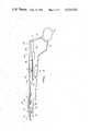
- FIG. 1is a perspective view of the ligator of the present invention illustrating the handles and jaws in their normal, open position.
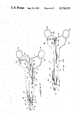
- FIG. 2is an exploded perspective view of the ligator of FIG. 1, illustrating all of its parts.
- FIG. 3is a plan view of the first handle without its cover.
- FIG. 4is a plan view of the instrument, partly in cross section, illustrating the clip tube, the feeder shoe and the constant-force coil spring.
- FIG. 5is a fragmentary, exploded, perspective view illustrating the clip tube, the feeder shoe, the constant-force coil spring and several clips.
- FIG. 6is a fragmentary plan view, partly in cross section, illustrating the clip ramp of the first handle.
- FIG. 7is a fragmentary, cross sectional, elevational view of the ramp structure of FIG. 6.
- FIG. 8is a fragmentary perspective view of the ramp structure of FIGS. 6 and 7.
- FIG. 9is a simplified, semi-diagrammatic plan view of the ligator of the present invention with its handles and jaws in their normal open position.
- FIG. 10is a simplified, semi-diagrammatic plan view illustrating the instrument of FIG. 9 with its handles in their one-quarter closed position.
- FIG. 11is a simplified, semi-diagrammatic plan view of the instrument of FIG. 9 with its handles and jaws in their fully-closed position.
- FIGS. 12-14are fragmentary perspective views illustrating the application and clamping of a clip on a vessel.
- FIG. 1illustrates the ligator of the present invention with its handles and jaws in normal open positions.
- the ligatoris generally indicated at 1, having a first handle 2, terminating in a first jaw 3 at its forward end.
- the ligatorhas a second handle 4 and a second jaw 5.
- the jaw 5 and the forward end of second handle 4are pivotally attached to the first handle 2 in such a way that second jaw 5 is actuated by second handle 4.
- handle 2is provided with a finger loop 2a and handle 4 is similarly provided with a finger loop 4a.
- the edge of handle 2 adjacent to finger loop 2ais provided with a serrated gripping surface 2b which extends partway onto finger loop 2a.
- the handle 4is provided with a gripping surface 4b along its edge adjacent to finger loop 4a and extending partway onto finger loop 4a.
- FIG. 2This Figure is an exploded view of the ligator of FIG. 1, illustrating all of its parts. To this end, first handle 2 is shown terminating in first jaw 3. Second handle 4 is also shown, together with second jaw 5.
- First handle 2is completed by a cover member 6.
- second handle 4is completed by a cover member 7.
- the ligatoris provided with a magazine or clip tube 8, a clip feeder shoe 9, a plurality of clips, four of which are shown at 10, a constant-force coil spring 11 and a cover 12 for the constant-force coil spring.
- the ligatorfurther comprises a pusher 13, a pusher coil spring 14 and a wire link 15.
- a handle biasing spring 16a jaw biasing spring 17 and a cover screw 18. All of these elements will be described in detail hereinafter.
- ligator of the present inventioncould be manufactured as a permanent, reusable surgical instrument, it lends itself well to being produced as a disposable, single-use instrument.
- all of the parts of the instrumentmay be readily molded of plastic with the exception of cover 6, clip tube 8, springs 11, 14, 16 and 17, wire link 15 and screw 18.
- These last mentioned elementsare preferably made of metal.
- Jaw 5is preferably made of a filled plastic for additional strength.
- the plastic and metallic materials from which the elements are mademust be chosen from those well known groups thereof which are compatible with a surgical environment and are capable of being sterilized by autoclave, ethylene oxide, irradiation, or other standard methods.
- FIG. 3illustrates, in the form of a plan view, the inside surface of first handle 2.
- the handle 2constitutes an elongated, integral, one-piece molded member. At its rearward end, the handle terminates in finger loop 2a. At its forward end, it terminates in first jaw 3.
- Handle 2is substantially surrounded by peripheral wall portions 19, 20 and 21.
- the wall 21extends to the first jaw 3 and terminates in a rounded end 21a containing a bore 22 adapted to receive first handle cover screw 18 (see FIG. 2), as will be described hereinafter.
- An internal longitudinal wall 23lies in parallel spaced relationship to the majority of wall 21, and together they define a longitudinal channel 24.
- the channel 24extends from the front end of handle 2, terminating at 24a. Near its forward end, the channel 24 contains a pair of sockets 25 and 26.
- Handle 2is provided with a second longitudinally extending internal wall 27, which cooperates with the wall 23 to confine pusher coil spring 14 (see FIG. 2), as will be described hereinafter.
- An integral post 28serves as a mount for one end of the pusher coil spring 14.
- a slightly inset continuation 27a of wall 27cooperates with an adjacent internal wall 29 to confine the wire link 15, again as will be described hereinafter.
- Between peripheral wall 21 and internal wall 29, the handle 2is provided with an elongated opening or slot 30, the purpose of which will be clear hereinafter.
- handle 2The forward end of handle 2 is notched as at 31 and is provided with a ramp structure generally indicated at 32 in channel 24.
- the notch 31 and ramp structure 32will be fully described hereinafter.
- a pivot bore 33is provided to receive pivot means by which the second jaw 5 and second handle 4 are pivotally affixed to handle 2.
- An elongated channel or slot 34is also formed in handle 2 to receive the base portion 16a of handle biasing spring 16 (see FIG. 2) by which the handles are biased to their open position, as will be described hereinafter.
- the clip tube 8comprises a metallic member of C-shaped cross section, the longitudinal edges of the clip tube 8 defining an elongated longitudinal slot 35 extending the length of the clip tube.
- ligator clipsmay be of any appropriate and well known configuration, they are each illustrated as comprising a V-shaped crown 10a, terminating in forwardly extending legs 10b and 10c.
- the forward end of the clip tube 8is notched as at 36 so as to conform to the shape of the crown 10a of the ligator clips.
- Feeder shoe 9comprises an elongated plastic member of such dimensions that it will be received within clip tube 8 with a sliding fit. At its forward end, the feeder shoe 9 is provided with bifurcations 9a and 9b adapted to abut either side of the crown portion 10a of the rearwardmost ligator clip of the row. At its rearward end, the feeder shoe has an upstanding lug 9c so dimensioned as to extend through clip tube slot 35 with a sliding fit.
- the constant-force spring 11(see FIG. 2) constitutes a ribbon-like spring formed into a U-shape having a base 11a and leg portions terminating in coils 11b and 11c.
- the spring 11is of the well-known type which exerts a substantially constant force regardless of the amount by which it is extended. Such springs are sold under the tradename "Neg-A-Tor".
- the base 11a of spring 11is adapted to be engaged about the upstanding lug 9c of feeder shoe 9.
- handle 2is provided with a ledge or shelf-like structure 37 extending along internal upstanding wall 23 within the channel 24.
- Ledge 37also surrounds sockets 25 and 26.
- peripheral wall portion 21is provided with a plurality of inwardly extending lugs 38.
- the upper surface of these lugs 38 and the upper surface of ledge 37are coplanar and are spaced upwardly from the bottom of channel 24.
- the lugs 38 and ledge 37are adapted to receive and support clip tube 8, with slot 35 of clip tube 8 facing toward the bottom of the channel 24 of handle 2. It will be understood that when the clip tube 8 is mounted in handle 2, its forward end (containing notch 36) will lie adjacent to the ramp structure 32 (see FIG. 3).
- FIG. 4is a plan view of the ligator instrument of FIG. 1, illustrating the opposite side of first handle 2 from that shown in FIG. 3.
- First handle 2, second handle 4 and second jaw 5are partially broken away to illustrate clip tube 8 mounted in place within handle 2.
- clip tube 8will contain a row of ligator clips 10 and feeder shoe 9.
- the upstanding lug 9c of feeder shoe 9will extend into the elongated channel 24 of handle 2.
- the constant-force coil spring 11will be mounted within the elongated channel 24 with its base portion 11a extending about the feeder shoe lug 9c and its coil portions 11b and 11c located respectively in sockets 25 and 26, as suggested by FIG. 4.
- Coil portions 11b and 11cwill be maintained in sockets 25 and 26 by cover 12 (see FIG. 2).
- the clip tube 8serves as a magazine for the ligator clips 10 and the ligator clips 10 are constantly urged forwardly (i.e. toward the instrument jaws) within clip tube 8 by the action of constant-force spring 11 on feeder shoe 9.
- the pusher 13comprises an elongated, flexible plastic member having a notch 13a at its forward end.
- the notch 13acorresponds to the V-shaped crown 10a of each ligator clip 10.
- the pusher 13is provided with an integral, transversely extending, cylindrical lug 13b.
- the lug 13bhas a small slot 13d formed therein, the purpose of which will be apparent hereinafter.
- the pusher 13is adapted to overlie clip tube 8 within the channel 24 of handle 2.
- the cylindrical lug 13b of pusher 13extends through the elongated slot 30 of handle 2 (see FIG. 3).
- the walls 21 and 23 of handle 2cooperate with the clip tube 8 to form a pusher track 13c for pusher 13.
- first jaw 3 and the second jaw 5are slightly curved, as is typical of many ligators, to facilitate the instrument's use and increase visibility of the clip during the clip clamping procedure.
- first jaw 3has a groove 39 formed therein and extending nearly to the end of the jaw.
- FIG. 2illustrates a corresponding groove 40 in second jaw 5.
- the grooves 39 and 40constitute continuations of the pusher track 13c.
- Pusher 13is shiftable within the pusher track 13c between a retracted position and an extended position.
- the retracted position of the pusheris illustrated in FIG. 11. It will be noted that the forward end 13a of pusher 13, when the pusher is in its retracted position, lies just behind the notched forward end 36 of clip tube 8.
- the forwardmost position of pusher 13is illustrated in FIG. 9. In its forwardmost position, the notched front end 13a of the pusher is located near the forward ends of jaw grooves 39 and 40 so that it can locate a ligator clip 10 at the forwardmost ends of these grooves.
- the means by which the pusher 13 is shifted between its retracted and extended positionswill be described hereinafter.
- pusher spring 14constituting a coil spring, has a hook-shaped configuration 14a at its forward end and a similar hook-like configuration 14b at its rearward end.
- Wire link 15has a hook-shaped forward end 15a and a short forwardly extending portion 15b at its rearward end.
- the forward end 14a of spring 14is mounted on post 28 of handle 2.
- the rearward end 14b of spring 14is engaged by the hook-shaped forward end 15a of wire link 15.
- the forwardly extending rearward end 15b of wire link 15is located in the slot 13d of lug 13b at the rearward end of pusher 13.
- the coil spring 14constantly urges pusher 13 forwardly, for reasons which will be apparent hereinafter.
- Handle biasing spring 16is in the form of a leaf spring, having a base portion 16a.
- the base portion 16ais located in the slot 34 formed in handle 2.
- the remainder of handle biasing spring 16is adapted to abut second handle 4 and its cover 7 to urge the second handle to its openmost position, as illustrated in FIG. 9.
- the first handle cover 6may be applied to handle 2 to complete this structure and to maintain all of the above mentioned elements in place therein.
- the first handle cover member 6has a flange 41 with an inturned edge 42.
- the flange 41is adapted to overlie a part of handle 2 peripheral wall 21.
- the peripheral wall 21is provided with a narrow slot 43.
- the inturned edge 42 of flange 41is adapted to engage slot 43 with a snap fit.
- the cover member 6has a second flange 44 with an inturned edge 45.
- the flange 44is adapted to overlie a part of the peripheral wall 19 of handle 2.
- Peripheral wall 19is provided with a longitudinal slot (not shown) similar to slot 43 of peripheral wall 21 and adapted to be engaged by the inturned edge 45 of flange 44 with a snap fit.
- Cover 6has a third flange 46. This flange overlies the peripheral portion of handle 2 containing the slot 34 in which the base 16a of handle biasing spring 16 is mounted. As a result, the base 16a of handle biasing spring 16 is captively mounted within first handle 2.
- the cover 6is provided with a fourth flange 47 adapted to enclose the forwardmost part of handle 2 and the upper part of first jaw 3.
- cover 6 and flange 47will be appropriately curved to match the curve of first jaw 3.
- coveris provided with a perforation 48 through which screw 18 extends and is threadedly engaged in the bore 22 of first handle 2 (see FIG. 3).
- cover 6is provided with a notch 49. The notch 49 is present to expose pivot bore 33 in first handle 2.
- the molded plastic jaw 5comprises a solid forward jaw portion containing the pusher track groove 40.
- the rearward portion of the jawis hollow, comprising a side wall 5a, a side wall 5b, a bottom wall 5c and a low end wall 5d. These walls define a chamber adapted to receive jaw biasing spring 17 (see also FIG. 9).
- Second jaw 5is mounted on first handle 2 with the forward portion of first handle 2 received between second jaw walls 5a and 5b and the forward portion of second jaw 5 adjacent to first jaw 3.
- the wall 5b of second jaw 5has a perforation 50 formed therein, adapted to be located coaxially with pivot bore 33 of first handle 2. It will be noted from FIG. 9 that when the second jaw 5 is in position on first handle 2, the notched portion 31 of first handle 2 closes the chamber formed by the walls 5a through 5d of second jaw 5.
- the jaw biasing spring 17acts upon the surface of notch 31 of first handle 2 and the wall 5c of second jaw 5 to urge the second jaw 5 to its open position as illustrated in FIG. 9.
- the wall 5b of second jaw 5has a notch 51 formed therein. This notch cooperates with an integral lug (not shown) on first handle 2 to determine the openmost position of second jaw 5.
- the wall 5b of second jaw 5also has a cam surface 52 thereon, the purpose of which will be evident hereinafter.
- Second handle 4has a transversely extending flange 53 containing a portion of finger grip 4b and extending about the forward end of finger loop 4a, as shown in FIG. 2.
- the second handle cover 7has a complimentary transversely extending flange 54, also containing a portion of finger grip 4b.
- second handle 4has a second transversely extending flange 55.
- Second handle cover 7has a corresponding flange 56.
- the mating edges of second handle flange 53 and second handle cover flange 54are intended to be joined together by any appropriate means such as gluing, welding or the like. The same is true of the mating edges of second handle flange 55 and second handle cover flange 56.
- second handle 4 and its cover 7are spaced from each other by a distance sufficient to just nicely receive the first handle 2 and its associated parts.
- the second handle 4at its forward end, has a laterally extending, cylindrical lug 57 with a bore 58 therein.
- second handle cover 7At a corresponding position, second handle cover 7 has a cylindrical lug 59 terminating in a pin 60.
- Lugs 57 and 59are intended to be joined together, with the pin 60 extending into the bore 58.
- Cylindrical lugs 57 and 59extend through the perforation 50 in the wall 5b of first jaw 5 and the pivot bore 33 of second handle 2, thereby serving as a pivot pin for handles 2 and 4, and second jaw 5.
- Second handle 4near its forward end, has a lug 61.
- the lug 61is so positioned as to contact the cam surface 52 of second jaw 5 to close the jaw, when first handle 2 and second handle 4 are closed.
- the second handle 4as shown in FIG. 2, is provided with an L-shaped groove 62 on its inside surface, near its rearward end.
- the L-shaped groove 62has a first leg 62a and a second leg 62b.
- the second handle cover 7has a corresponding L-shaped groove 63 with legs 63a and 63b.
- the grooves 62 and 63are mirror images of each other.
- FIG. 9being a somewhat simplified drawing, illustrates first handle 2 without its cover 6 and second handle 4, without its cover 7.
- second jaw 5is partially broken away.
- the transverse cylindrical lug 13b of pusher 13extends downwardly through rectilinear slot 30 of first handle 2 and is engaged in the groove 62 of second handle 4. It will be understood that the other end of transverse cylindrical lug 13b will similarly be located in the groove 63 of second handle cover 7, occupying the same relative position therein.
- first handle 2 and second handle 4are shown in their open positions, as determined by the transverse cylindrical lug 13b of pusher 13 being located at the free end of second handle groove leg 62a.
- the slot 30 of first handle 2 and the groove leg 62a of second handle 4will cooperate to shift transverse pusher lug 13b rearwardly, thus shifting pusher 13 toward its retracted position.
- the transverse pusher lug 13bwill have nearly reached the juncture of second handle groove legs 62a and 62b.
- FIG. 11illustrates first handle 2 and second handle 4 in their fully closed position.
- Ramp 32is best illustrated in FIGS. 6-8.
- a surface 64just rearwardly of ramp 32, there is a surface 64.
- the surface 64lies in the same plane as the ledge 37 and lugs 38 which support the clip tube 8.
- the surface 64is adapted to support the forwardmost end of clip tube 8.
- shoulders 65 and 66At the forward end of surface 64, there are shoulders 65 and 66 with substantially coplanar vertical shoulders 67 and 68.
- the shoulders 65-68constitute abutment surfaces for the forward end of clip tube 8 and these abutment surfaces are of a dimension slightly less than the thickness of the metal from which the clip tube 8 is made.
- the ramp 32comprises parallel spaced ramp surfaces 69 and 70 which gradually slope upwardly and forwardly.
- Ramp surfaces 69 and 70terminate respectively in ramp surfaces 71 and 72 which slope forwardly and upwardly at a steeper angle.
- Surfaces 69 and 71are separated from surfaces 70 and 72 by a wall or projection 73 which, at its rearward end, is V-shaped, terminating in upwardly and forwardly sloping surfaces 74 and 75.
- the upwardly and forwardly sloping surfaces 71 and 72 and the upwardly and forwardly sloping surfaces 74 and 75terminate in the planar upper surface 76 of the ramp 32 which is substantially coplanar with the upper surface of clip tube 8 and constitutes a part of the pusher track 13c for pusher 13.
- the surfaces 69 and 71cooperate with one leg of a forwardmost clip of the row being ramped and surfaces 70 and 72 cooperate with its other leg.
- the surfaces 74 and 75cooperate with the crown portion 10a of the forwardmost clip to cause the clip to shift from clip tube 8 to the pusher track 13c while always remaining in a plane substantially parallel to that of the clip tube 8 and that of the pusher track 13c. This is demonstrated in FIGS. 6 and 7.
- the forward ends of the second clip 10ewill ultimately lose contact with the crown portion of the first clip 10d and will begin to slip under the first clip 10d completing its shift into the pusher track 13c and into abutment with cover 6.
- the pusher 13When the pusher 13 is again shifted to its extended position, it will locate the forwardmost clip 10d between jaws 3 and 5 with the forward ends of the legs of clip 10d abutting the ends of jaw grooves 39 and 40, which constitute a part of the pusher track 13c. Meanwhile, the pusher 13 again overlies the upper surface 76 of ramp 32 preventing further forward movement of second clip 10e under the urging of third clip 10f. In this way, each clip in its turn is shifted from clip tube 8 to the pusher track 13c by the ramp structure 32 which operates in a simple and efficient manner with no moving parts.
- the ligator 1 of the present inventionhaving been described in detail, its operation can be set forth as follows.
- the ligatorwill be assembled, loaded with clips, packaged and sterilized by any of the methods mentioned above.
- the ligatorwill be removed from its package and handed to the surgeon with its first handle 2 and second handle 4 in their normal, open positions.
- the ligatormay be packaged with a first clip located between jaws 3 and 5. If not, then the surgeon will have to cycle the ligator once to bring a first clip into position for clamping between jaws 3 and 5.
- the instrument, ready for use,is illustrated in FIGS. 1 and 9.
- pusher 13Once pusher 13 achieves its retracted position (FIG. 10), it exposes ramp 32.
- the row of clips within clip tube 8is then free to move forwardly under the influence of feeder shoe 9 and constant-force spring 11.
- ramp 32Through the agency of ramp 32, the next forwardmost clip of the row is ramped into the pusher track.
- the next clip of the rowis located in the pusher track 13c while the surgeon is completing the clip-clamping step. This action is automatic and requires no force to be exerted by the surgeon and no additional manipulation on his part.
- first jaw 3be provided with an integral pin.
- a pinis shown at 77 in FIG. 2.
- the free end of pin 77is adapted to be received in a perforation 78 in second jaw 5 (see FIG. 2).
- Pin 77is of such length that its free end extends into perforation 78 of second jaw 5, even when the jaws 3 and 5 are in their open positions. When the jaws 3 and 5 are shifted to their closed position, pin 77 is totally received within perforation 78.
- Pin 77is so positioned on jaw 3 that it lies to the side of and adjacent the apex of the crown portion of the forwardmost clip when located in its clamping position at the forward end of jaws 3 and 5. This is illustrated in FIGS. 12 and 14.
- FIG. 12this Figure illustrates a clip 10 being located about a vessel 79 to be clamped.
- the vesselis inserted between the legs of clip 10 and the ligating instrument 1 is shifted forwardly until vessel 79 contacts pin 77.
- the pin 77precludes locating vessel 79 too deeply between jaws 3 and 5, inadvertently shoving clip 10 and pusher 13 rearwardly.
- pin 77assures proper positioning of vessel 79 and assures that the clip 10 will remain in its proper position relative to jaws 3 and 5 for clamping.
- the pusher 13shifts rearwardly and then jaws 3 and 5 begin to close.
- the free ends of its legswill come together as shown in FIG. 13, assuring that the clip 10 envelops the vessel 79. Further closing of the jaws will flatten the clip 10 thoroughly clamping the vessel 79.
- the configuration of the ligating instrument and grooves 62 and 63is such that too much clamping pressure cannot be applied to the clip and the clip cannot be over-clamped.
- the ligator meansmay be provided with indicator means (not shown) or a window (not shown) providing the surgeon with a visual indication of the number of clips remaining in the instrument.
- first handle and second handle 4and thus the jaws 3 and 5 in their open positions after the last ligator clip has been clamped. This can be accomplished in a number of ways.
- FIG. 2A very simple way is illustrated in FIG. 2.
Landscapes
- Health & Medical Sciences (AREA)
- Surgery (AREA)
- Life Sciences & Earth Sciences (AREA)
- Heart & Thoracic Surgery (AREA)
- Nuclear Medicine, Radiotherapy & Molecular Imaging (AREA)
- Vascular Medicine (AREA)
- Engineering & Computer Science (AREA)
- Biomedical Technology (AREA)
- Reproductive Health (AREA)
- Medical Informatics (AREA)
- Molecular Biology (AREA)
- Animal Behavior & Ethology (AREA)
- General Health & Medical Sciences (AREA)
- Public Health (AREA)
- Veterinary Medicine (AREA)
- Surgical Instruments (AREA)
Abstract
Description
Claims (30)
Priority Applications (19)
| Application Number | Priority Date | Filing Date | Title |
|---|---|---|---|
| US06/435,380US4534351A (en) | 1982-10-20 | 1982-10-20 | Ligator |
| GB08310748AGB2128477B (en) | 1982-10-20 | 1983-04-20 | Ligator |
| CA000426285ACA1200453A (en) | 1982-10-20 | 1983-04-20 | Ligator |
| AU13830/83AAU566763B2 (en) | 1982-10-20 | 1983-04-21 | Ligator-clip |
| SE8302260ASE453256B (en) | 1982-10-20 | 1983-04-21 | LIGATOR FOR APPLICATION OF CLAMMERS A BLOOD BLOOD |
| ES1983281090UES281090Y (en) | 1982-10-20 | 1983-04-29 | SURGICAL LINKER. |
| NL8301523ANL8301523A (en) | 1982-10-20 | 1983-04-29 | STRAP. |
| ZA833052AZA833052B (en) | 1982-10-20 | 1983-04-29 | Ligator |
| JP58090822AJPS5975046A (en) | 1982-10-20 | 1983-05-25 | Ligature device |
| BE0/210850ABE896847A (en) | 1982-10-20 | 1983-05-26 | LIGATING DEVICE. |
| IT67603/83AIT1159020B (en) | 1982-10-20 | 1983-05-31 | BINDING TOOL |
| BR8303015ABR8303015A (en) | 1982-10-20 | 1983-06-07 | CONNECTION DEVICE FOR APPLYING CONNECTION CLAMPS IN BLOOD VASES |
| AR293268AAR229225A1 (en) | 1982-10-20 | 1983-06-07 | BINDING INSTRUMENT TO APPLY SEALING CLOSURES OR BLOOD VESSEL CLOSURES |
| FR8310256AFR2534802B1 (en) | 1982-10-20 | 1983-06-21 | INSTRUMENT OF SURGICAL LIGATION |
| DE3323671ADE3323671C2 (en) | 1982-10-20 | 1983-07-01 | Ligature instrument for applying clamps to blood vessels or the like. |
| CH3785/83ACH663532A5 (en) | 1982-10-20 | 1983-07-08 | LIGATURE INSTRUMENT. |
| KR1019830003309AKR900004142B1 (en) | 1982-10-20 | 1983-07-19 | Ligature device |
| DD83254818ADD211278A5 (en) | 1982-10-20 | 1983-09-14 | LIGATURKLAMMERINSTRUMENT |
| MX199153AMX156987A (en) | 1982-10-20 | 1983-10-19 | IMPROVEMENTS TO BINDER TO HOLD BLOOD AND SIMILAR GLASSES |
Applications Claiming Priority (1)
| Application Number | Priority Date | Filing Date | Title |
|---|---|---|---|
| US06/435,380US4534351A (en) | 1982-10-20 | 1982-10-20 | Ligator |
Publications (1)
| Publication Number | Publication Date |
|---|---|
| US4534351Atrue US4534351A (en) | 1985-08-13 |
Family
ID=23728148
Family Applications (1)
| Application Number | Title | Priority Date | Filing Date |
|---|---|---|---|
| US06/435,380Expired - LifetimeUS4534351A (en) | 1982-10-20 | 1982-10-20 | Ligator |
Country Status (19)
| Country | Link |
|---|---|
| US (1) | US4534351A (en) |
| JP (1) | JPS5975046A (en) |
| KR (1) | KR900004142B1 (en) |
| AR (1) | AR229225A1 (en) |
| AU (1) | AU566763B2 (en) |
| BE (1) | BE896847A (en) |
| BR (1) | BR8303015A (en) |
| CA (1) | CA1200453A (en) |
| CH (1) | CH663532A5 (en) |
| DD (1) | DD211278A5 (en) |
| DE (1) | DE3323671C2 (en) |
| ES (1) | ES281090Y (en) |
| FR (1) | FR2534802B1 (en) |
| GB (1) | GB2128477B (en) |
| IT (1) | IT1159020B (en) |
| MX (1) | MX156987A (en) |
| NL (1) | NL8301523A (en) |
| SE (1) | SE453256B (en) |
| ZA (1) | ZA833052B (en) |
Cited By (162)
| Publication number | Priority date | Publication date | Assignee | Title |
|---|---|---|---|---|
| US4572183A (en)* | 1984-11-26 | 1986-02-25 | Senmed, Inc. | Positive feed system for a surgical ligating instrument |
| US4674504A (en)* | 1982-10-06 | 1987-06-23 | Klieman Charles H | Spring activated hemostatic clip applicator |
| US4712549A (en)* | 1985-07-01 | 1987-12-15 | Edward Weck & Co. | Automatic hemostatic clip applier |
| US4850355A (en)* | 1987-04-06 | 1989-07-25 | Richard-Allan Medical Industries, Inc. | Hemostatic clip applicator for applying multiple hemostatic clips |
| US5030226A (en)* | 1988-01-15 | 1991-07-09 | United States Surgical Corporation | Surgical clip applicator |
| US5049152A (en)* | 1989-03-07 | 1991-09-17 | Richard-Allan Medical Industries | Hemostatic clip applicator |
| US5104395A (en)* | 1989-07-03 | 1992-04-14 | Edward Weck Incorporated | Automatic hemostatic clip applicator |
| US5171249A (en)* | 1991-04-04 | 1992-12-15 | Ethicon, Inc. | Endoscopic multiple ligating clip applier |
| USD332491S (en) | 1990-07-30 | 1993-01-12 | Codman & Shurtleff, Inc. | Surgical clip applier |
| US5197970A (en)* | 1988-01-15 | 1993-03-30 | United States Surgical Corporation | Surgical clip applicator |
| US5207692A (en)* | 1990-07-30 | 1993-05-04 | Codman & Shurtleff, Inc. | Surgical clip applier with reciprocating clip sleeve and dual ratchet mechanism |
| US5300081A (en)* | 1992-10-09 | 1994-04-05 | United States Surgical Corporation | Surgical clip applier having clip advancement control |
| US5382254A (en)* | 1989-07-18 | 1995-01-17 | United States Surgical Corporation | Actuating handle for surgical instruments |
| US5382255A (en)* | 1993-01-08 | 1995-01-17 | United States Surgical Corporation | Apparatus and method for assembly of surgical instruments |
| US5383881A (en)* | 1989-07-18 | 1995-01-24 | United States Surgical Corporation | Safety device for use with endoscopic instrumentation |
| US5431668A (en)* | 1993-04-29 | 1995-07-11 | Ethicon, Inc. | Ligating clip applier |
| US5607436A (en)* | 1993-10-08 | 1997-03-04 | United States Surgical Corporation | Apparatus for applying surgical clips |
| US5643291A (en)* | 1994-09-29 | 1997-07-01 | United States Surgical Corporation | Surgical clip applicator |
| US5645551A (en)* | 1989-07-18 | 1997-07-08 | United States Surgical Corporation | Apparatus and method for applying surgical clips |
| US5700270A (en)* | 1995-10-20 | 1997-12-23 | United States Surgical Corporation | Surgical clip applier |
| US5700271A (en)* | 1995-10-20 | 1997-12-23 | United States Surgical Corporation | Apparatus for applying surgical clips |
| US5707380A (en)* | 1996-07-23 | 1998-01-13 | United States Surgical Corporation | Anastomosis instrument and method |
| US5772673A (en)* | 1996-03-07 | 1998-06-30 | United States Surgical Corporation | Apparatus for applying surgical clips |
| US5833696A (en)* | 1996-10-03 | 1998-11-10 | United States Surgical Corporation | Apparatus for applying surgical clips |
| US5868759A (en)* | 1997-10-10 | 1999-02-09 | United States Surgical Corporation | Surgical clip applier |
| US5951574A (en)* | 1998-10-23 | 1999-09-14 | Ethicon Endo-Surgery, Inc. | Multiple clip applier having a split feeding mechanism |
| US5997552A (en)* | 1995-10-20 | 1999-12-07 | United States Surgical Corporation | Meniscal fastener applying device |
| US6004341A (en)* | 1996-12-05 | 1999-12-21 | Loma Linda University Medical Center | Vascular wound closure device |
| US6024748A (en)* | 1996-07-23 | 2000-02-15 | United States Surgical Corporation | Singleshot anastomosis instrument with detachable loading unit and method |
| US6059799A (en)* | 1998-06-25 | 2000-05-09 | United States Surgical Corporation | Apparatus for applying surgical clips |
| US6287322B1 (en) | 1995-12-07 | 2001-09-11 | Loma Linda University Medical Center | Tissue opening locator and everter and method |
| US20020019642A1 (en)* | 1996-07-23 | 2002-02-14 | Keith Milliman | Anastomosis instrument and method for performing same |
| US6425901B1 (en) | 1995-12-07 | 2002-07-30 | Loma Linda University Medical Center | Vascular wound closure system |
| US20020177860A1 (en)* | 1996-07-23 | 2002-11-28 | Nicholas David A. | Anastomosis instrument and method |
| US6524326B1 (en) | 1995-12-07 | 2003-02-25 | Loma Linda University Medical Center | Tissue opening locator and everter and method |
| US20030222117A1 (en)* | 2002-05-31 | 2003-12-04 | Orban Joseph P. | End-to-end anastomosis instrument and method for performing same |
| US6666872B2 (en) | 2000-04-11 | 2003-12-23 | United States Surgical | Single shot meniscal repair device |
| US20040006372A1 (en)* | 2000-10-20 | 2004-01-08 | Racenet David C. | Directionally biased staple and method of manufacturing |
| US20040010274A1 (en)* | 2002-07-10 | 2004-01-15 | Manzo Scott E. | Anastomosis instrument and method for performing same |
| US20040092971A1 (en)* | 1996-07-23 | 2004-05-13 | Kevin Sniffin | Anastomosis instrument and method for performing same |
| US6890342B2 (en) | 2000-08-02 | 2005-05-10 | Loma Linda University | Method and apparatus for closing vascular puncture using hemostatic material |
| US6896683B1 (en) | 1999-01-25 | 2005-05-24 | Applied Material Resources Corporation | Surgical instrument with improved handle assembly |
| US20050177177A1 (en)* | 2002-04-10 | 2005-08-11 | Viola Frank J. | Surgical clip applier with high torque jaws |
| US20060160041A1 (en)* | 2003-03-07 | 2006-07-20 | Marleen Falle | Candle Reshaper |
| US7195142B2 (en) | 2003-05-30 | 2007-03-27 | Tyco Healthcare Group Lp | End-to-end anastomosis instrument and method for performing same |
| US20070073314A1 (en)* | 2005-09-29 | 2007-03-29 | Applied Medical Resources Corporation | Manually actuated surgical clip applier |
| US7223273B2 (en) | 1996-07-23 | 2007-05-29 | Tyco Healthcare Group Lp | Anastomosis instrument and method for performing same |
| US7637917B2 (en) | 2004-10-08 | 2009-12-29 | Tyco Healthcare Group Lp | Endoscopic surgical clip applier |
| USD625009S1 (en) | 2006-03-24 | 2010-10-05 | Tyco Healthcare Group Lp | Surgical clip applier |
| US7819886B2 (en) | 2004-10-08 | 2010-10-26 | Tyco Healthcare Group Lp | Endoscopic surgical clip applier |
| USD629101S1 (en) | 2006-03-24 | 2010-12-14 | Tyco Healthcare Group Lp | Surgical clip applier |
| US20110060356A1 (en)* | 2009-09-09 | 2011-03-10 | Tyco Healthcare Group Lp | Low Profile Cutting Assembly with a Return Spring |
| US8056565B2 (en) | 2008-08-25 | 2011-11-15 | Tyco Healthcare Group Lp | Surgical clip applier and method of assembly |
| US8128643B2 (en) | 2006-10-17 | 2012-03-06 | Tyco Healthcare Group Lp | Apparatus for applying surgical clips |
| US8267944B2 (en) | 2008-08-29 | 2012-09-18 | Tyco Healthcare Group Lp | Endoscopic surgical clip applier with lock out |
| US8382773B2 (en) | 2007-03-26 | 2013-02-26 | Covidien Lp | Endoscopic surgical clip applier |
| US8403945B2 (en) | 2010-02-25 | 2013-03-26 | Covidien Lp | Articulating endoscopic surgical clip applier |
| US8403946B2 (en) | 2010-07-28 | 2013-03-26 | Covidien Lp | Articulating clip applier cartridge |
| US8409223B2 (en) | 2008-08-29 | 2013-04-02 | Covidien Lp | Endoscopic surgical clip applier with clip retention |
| US8409222B2 (en) | 2004-10-08 | 2013-04-02 | Covidien Lp | Endoscopic surgical clip applier |
| US8465502B2 (en) | 2008-08-25 | 2013-06-18 | Covidien Lp | Surgical clip applier and method of assembly |
| US8506580B2 (en) | 2007-04-11 | 2013-08-13 | Covidien Lp | Surgical clip applier |
| US8545486B2 (en) | 2009-12-15 | 2013-10-01 | Covidien Lp | Surgical clip applier |
| US8585717B2 (en) | 2008-08-29 | 2013-11-19 | Covidien Lp | Single stroke endoscopic surgical clip applier |
| US8652152B2 (en) | 2004-09-23 | 2014-02-18 | Covidien Lp | Clip applying apparatus and ligation clip |
| US8734469B2 (en) | 2009-10-13 | 2014-05-27 | Covidien Lp | Suture clip applier |
| US8900253B2 (en) | 2003-03-11 | 2014-12-02 | Covidien Lp | Clip applying apparatus with angled jaw |
| US8920438B2 (en) | 2004-10-08 | 2014-12-30 | Covidien Lp | Apparatus for applying surgical clips |
| US8968337B2 (en) | 2010-07-28 | 2015-03-03 | Covidien Lp | Articulating clip applier |
| US9011464B2 (en) | 2010-11-02 | 2015-04-21 | Covidien Lp | Self-centering clip and jaw |
| US9113892B2 (en) | 2013-01-08 | 2015-08-25 | Covidien Lp | Surgical clip applier |
| US9186153B2 (en) | 2011-01-31 | 2015-11-17 | Covidien Lp | Locking cam driver and jaw assembly for clip applier |
| US9186136B2 (en) | 2009-12-09 | 2015-11-17 | Covidien Lp | Surgical clip applier |
| US9358015B2 (en) | 2008-08-29 | 2016-06-07 | Covidien Lp | Endoscopic surgical clip applier with wedge plate |
| US9364239B2 (en) | 2011-12-19 | 2016-06-14 | Covidien Lp | Jaw closure mechanism for a surgical clip applier |
| US9364216B2 (en) | 2011-12-29 | 2016-06-14 | Covidien Lp | Surgical clip applier with integrated clip counter |
| US9408610B2 (en) | 2012-05-04 | 2016-08-09 | Covidien Lp | Surgical clip applier with dissector |
| US9414844B2 (en) | 2008-08-25 | 2016-08-16 | Covidien Lp | Surgical clip appliers |
| US9532787B2 (en) | 2012-05-31 | 2017-01-03 | Covidien Lp | Endoscopic clip applier |
| US9750500B2 (en) | 2013-01-18 | 2017-09-05 | Covidien Lp | Surgical clip applier |
| US9763668B2 (en) | 2004-10-08 | 2017-09-19 | Covidien Lp | Endoscopic surgical clip applier |
| US9775623B2 (en) | 2011-04-29 | 2017-10-03 | Covidien Lp | Surgical clip applier including clip relief feature |
| US9775624B2 (en) | 2013-08-27 | 2017-10-03 | Covidien Lp | Surgical clip applier |
| US9931124B2 (en) | 2015-01-07 | 2018-04-03 | Covidien Lp | Reposable clip applier |
| US9968362B2 (en) | 2013-01-08 | 2018-05-15 | Covidien Lp | Surgical clip applier |
| US20180235632A1 (en)* | 2017-02-22 | 2018-08-23 | Covidien Lp | Surgical clip applier including inserts for jaw assembly |
| WO2018175651A1 (en)* | 2017-03-21 | 2018-09-27 | Teleflex Medical Incorporated | Clip applier having stabilizing member |
| US20180344320A1 (en)* | 2017-06-05 | 2018-12-06 | Wieslaw Mieczyslaw Brodaczewski | Linear cutter stapler |
| US10159491B2 (en) | 2015-03-10 | 2018-12-25 | Covidien Lp | Endoscopic reposable surgical clip applier |
| US10292712B2 (en) | 2015-01-28 | 2019-05-21 | Covidien Lp | Surgical clip applier with integrated cutter |
| US10390831B2 (en) | 2015-11-10 | 2019-08-27 | Covidien Lp | Endoscopic reposable surgical clip applier |
| US10426489B2 (en) | 2016-11-01 | 2019-10-01 | Covidien Lp | Endoscopic reposable surgical clip applier |
| US10492782B2 (en) | 2002-06-25 | 2019-12-03 | Incisive Surgical, Inc. | Mechanical method and apparatus for bilateral tissue fastening |
| US10492795B2 (en) | 2016-11-01 | 2019-12-03 | Covidien Lp | Endoscopic surgical clip applier |
| US10548602B2 (en) | 2017-02-23 | 2020-02-04 | Covidien Lp | Endoscopic surgical clip applier |
| US10582931B2 (en) | 2016-02-24 | 2020-03-10 | Covidien Lp | Endoscopic reposable surgical clip applier |
| US10610236B2 (en) | 2016-11-01 | 2020-04-07 | Covidien Lp | Endoscopic reposable surgical clip applier |
| US10639044B2 (en) | 2016-10-31 | 2020-05-05 | Covidien Lp | Ligation clip module and clip applier |
| US10639032B2 (en) | 2017-06-30 | 2020-05-05 | Covidien Lp | Endoscopic surgical clip applier including counter assembly |
| US10653429B2 (en) | 2017-09-13 | 2020-05-19 | Covidien Lp | Endoscopic surgical clip applier |
| US10660725B2 (en) | 2017-02-14 | 2020-05-26 | Covidien Lp | Endoscopic surgical clip applier including counter assembly |
| US10660723B2 (en) | 2017-06-30 | 2020-05-26 | Covidien Lp | Endoscopic reposable surgical clip applier |
| US10660651B2 (en) | 2016-10-31 | 2020-05-26 | Covidien Lp | Endoscopic reposable surgical clip applier |
| US10675112B2 (en) | 2017-08-07 | 2020-06-09 | Covidien Lp | Endoscopic surgical clip applier including counter assembly |
| US10675043B2 (en) | 2017-05-04 | 2020-06-09 | Covidien Lp | Reposable multi-fire surgical clip applier |
| US10702279B2 (en) | 2015-11-03 | 2020-07-07 | Covidien Lp | Endoscopic surgical clip applier |
| US10702280B2 (en) | 2015-11-10 | 2020-07-07 | Covidien Lp | Endoscopic reposable surgical clip applier |
| US10702278B2 (en) | 2014-12-02 | 2020-07-07 | Covidien Lp | Laparoscopic surgical ligation clip applier |
| US10709455B2 (en) | 2017-02-02 | 2020-07-14 | Covidien Lp | Endoscopic surgical clip applier |
| US10722235B2 (en) | 2017-05-11 | 2020-07-28 | Covidien Lp | Spring-release surgical clip |
| US10722236B2 (en) | 2017-12-12 | 2020-07-28 | Covidien Lp | Endoscopic reposable surgical clip applier |
| US10743887B2 (en) | 2017-12-13 | 2020-08-18 | Covidien Lp | Reposable multi-fire surgical clip applier |
| US10758245B2 (en) | 2017-09-13 | 2020-09-01 | Covidien Lp | Clip counting mechanism for surgical clip applier |
| US10758244B2 (en) | 2017-02-06 | 2020-09-01 | Covidien Lp | Endoscopic surgical clip applier |
| US10765431B2 (en) | 2016-01-18 | 2020-09-08 | Covidien Lp | Endoscopic surgical clip applier |
| US10786262B2 (en) | 2017-08-09 | 2020-09-29 | Covidien Lp | Endoscopic reposable surgical clip applier |
| US10786263B2 (en) | 2017-08-15 | 2020-09-29 | Covidien Lp | Endoscopic reposable surgical clip applier |
| US10786273B2 (en) | 2018-07-13 | 2020-09-29 | Covidien Lp | Rotation knob assemblies for handle assemblies |
| US10806464B2 (en) | 2016-08-11 | 2020-10-20 | Covidien Lp | Endoscopic surgical clip applier and clip applying systems |
| US10806463B2 (en) | 2011-11-21 | 2020-10-20 | Covidien Lp | Surgical clip applier |
| US10828036B2 (en) | 2017-11-03 | 2020-11-10 | Covidien Lp | Endoscopic surgical clip applier and handle assemblies for use therewith |
| US10835260B2 (en) | 2017-09-13 | 2020-11-17 | Covidien Lp | Endoscopic surgical clip applier and handle assemblies for use therewith |
| US10835341B2 (en) | 2017-09-12 | 2020-11-17 | Covidien Lp | Endoscopic surgical clip applier and handle assemblies for use therewith |
| US10849630B2 (en) | 2017-12-13 | 2020-12-01 | Covidien Lp | Reposable multi-fire surgical clip applier |
| US10863992B2 (en) | 2017-08-08 | 2020-12-15 | Covidien Lp | Endoscopic surgical clip applier |
| US10905425B2 (en) | 2015-11-10 | 2021-02-02 | Covidien Lp | Endoscopic reposable surgical clip applier |
| US10925616B2 (en) | 2017-03-21 | 2021-02-23 | Teleflex Medical Incorporated | Clip applier with replaceable tips |
| US10932790B2 (en) | 2017-08-08 | 2021-03-02 | Covidien Lp | Geared actuation mechanism and surgical clip applier including the same |
| US10932791B2 (en) | 2017-11-03 | 2021-03-02 | Covidien Lp | Reposable multi-fire surgical clip applier |
| US10932793B2 (en) | 2016-01-11 | 2021-03-02 | Covidien Lp | Endoscopic reposable surgical clip applier |
| US10945734B2 (en) | 2017-11-03 | 2021-03-16 | Covidien Lp | Rotation knob assemblies and surgical instruments including the same |
| US10959737B2 (en) | 2017-12-13 | 2021-03-30 | Covidien Lp | Reposable multi-fire surgical clip applier |
| US10993721B2 (en) | 2018-04-25 | 2021-05-04 | Covidien Lp | Surgical clip applier |
| US11033256B2 (en) | 2018-08-13 | 2021-06-15 | Covidien Lp | Linkage assembly for reusable surgical handle assemblies |
| US11045195B2 (en) | 2014-04-25 | 2021-06-29 | Incisive Surgical, Inc. | Method and apparatus for wound closure with sequential tissue positioning and retention |
| US11051827B2 (en) | 2018-01-16 | 2021-07-06 | Covidien Lp | Endoscopic surgical instrument and handle assemblies for use therewith |
| US11051828B2 (en) | 2018-08-13 | 2021-07-06 | Covidien Lp | Rotation knob assemblies and surgical instruments including same |
| US11058432B2 (en) | 2015-01-15 | 2021-07-13 | Covidien Lp | Endoscopic reposable surgical clip applier |
| US11071553B2 (en) | 2016-08-25 | 2021-07-27 | Covidien Lp | Endoscopic surgical clip applier and clip applying systems |
| US11116514B2 (en) | 2017-02-06 | 2021-09-14 | Covidien Lp | Surgical clip applier with user feedback feature |
| US11116513B2 (en) | 2017-11-03 | 2021-09-14 | Covidien Lp | Modular surgical clip cartridge |
| US11147566B2 (en) | 2018-10-01 | 2021-10-19 | Covidien Lp | Endoscopic surgical clip applier |
| US11160559B2 (en) | 2017-03-21 | 2021-11-02 | Teleflex Medical Incorporated | Clip applier with stabilizing member |
| US11219463B2 (en) | 2018-08-13 | 2022-01-11 | Covidien Lp | Bilateral spring for surgical instruments and surgical instruments including the same |
| US11246601B2 (en) | 2018-08-13 | 2022-02-15 | Covidien Lp | Elongated assemblies for surgical clip appliers and surgical clip appliers incorporating the same |
| US11253267B2 (en) | 2018-08-13 | 2022-02-22 | Covidien Lp | Friction reduction mechanisms for handle assemblies |
| US11259887B2 (en) | 2018-08-10 | 2022-03-01 | Covidien Lp | Feedback mechanisms for handle assemblies |
| US11278267B2 (en) | 2018-08-13 | 2022-03-22 | Covidien Lp | Latch assemblies and surgical instruments including the same |
| US11344316B2 (en) | 2018-08-13 | 2022-05-31 | Covidien Lp | Elongated assemblies for surgical clip appliers and surgical clip appliers incorporating the same |
| US11376015B2 (en) | 2017-11-03 | 2022-07-05 | Covidien Lp | Endoscopic surgical clip applier and handle assemblies for use therewith |
| US11524398B2 (en) | 2019-03-19 | 2022-12-13 | Covidien Lp | Gear drive mechanisms for surgical instruments |
| US11534177B2 (en) | 2017-03-21 | 2022-12-27 | Teleflex Medical Incorporated | Flexible stabilizing member for a clip applier |
| US11583291B2 (en) | 2017-02-23 | 2023-02-21 | Covidien Lp | Endoscopic surgical clip applier |
| US11607227B2 (en) | 2017-03-21 | 2023-03-21 | Teleflex Medical Incorporated | Surgical clip and clip applier |
| US11723669B2 (en) | 2020-01-08 | 2023-08-15 | Covidien Lp | Clip applier with clip cartridge interface |
| US11779340B2 (en) | 2020-01-02 | 2023-10-10 | Covidien Lp | Ligation clip loading device |
| US12023041B2 (en) | 2017-03-21 | 2024-07-02 | Teleflex Medical Incorporated | Clip applier |
| CN118697399A (en)* | 2024-07-31 | 2024-09-27 | 南京鼓楼医院 | A vascular suture device |
| US12114866B2 (en) | 2020-03-26 | 2024-10-15 | Covidien Lp | Interoperative clip loading device |
| US12279774B2 (en) | 2018-09-26 | 2025-04-22 | Teleflex Medical Incorporated | Clip applier with stabilizing member |
| US12318094B2 (en) | 2019-09-26 | 2025-06-03 | Teleflex Medical Incorporated | Clip applier |
| US12419648B2 (en) | 2022-09-26 | 2025-09-23 | Covidien Lp | Two-part fasteners for surgical clip appliers and surgical clip appliers for deploying the same |
Families Citing this family (1)
| Publication number | Priority date | Publication date | Assignee | Title |
|---|---|---|---|---|
| CA2060281A1 (en)* | 1991-02-20 | 1992-08-21 | John C. Phillips | Hemostatic clip applier |
Citations (9)
| Publication number | Priority date | Publication date | Assignee | Title |
|---|---|---|---|---|
| US3082426A (en)* | 1960-06-17 | 1963-03-26 | George Oliver Halsted | Surgical stapling device |
| US3270745A (en)* | 1963-06-11 | 1966-09-06 | Rene G Le Vaux | Hemostatic clip constructions |
| US3463156A (en)* | 1965-05-27 | 1969-08-26 | Edward B Mcdermott | Hemostatic clip and applicator |
| US4152920A (en)* | 1977-10-17 | 1979-05-08 | United States Surgical Corporation | System for applying surgical clips |
| US4166466A (en)* | 1976-10-08 | 1979-09-04 | Jarvik Robert K | Repeating hemostatic clip applying instruments and multi-clip cartridges therefor |
| US4299224A (en)* | 1979-06-06 | 1981-11-10 | United States Surgical Corporation | Disposable clip applier |
| US4316468A (en)* | 1977-08-05 | 1982-02-23 | Charles H. Klieman | Surgical stapler |
| US4325376A (en)* | 1977-08-05 | 1982-04-20 | Charles H. Klieman | Hemostatic clip applicator |
| US4430997A (en)* | 1980-11-19 | 1984-02-14 | Ethicon, Inc. | Multiple clip applier |
Family Cites Families (6)
| Publication number | Priority date | Publication date | Assignee | Title |
|---|---|---|---|---|
| US4086926A (en)* | 1976-10-08 | 1978-05-02 | United States Surgical Corporation | Ligating and dividing organic structures |
| US4296751A (en)* | 1979-08-02 | 1981-10-27 | Blake Joseph W Iii | Surgical device |
| US4480640A (en)* | 1980-04-22 | 1984-11-06 | Senco Products, Inc. | Ligating device |
| US4565199A (en)* | 1980-04-22 | 1986-01-21 | Senmed, Inc. | Ligator |
| US4471780A (en)* | 1982-02-05 | 1984-09-18 | Ethicon, Inc. | Multiple ligating clip applier instrument |
| US4478220A (en)* | 1982-02-05 | 1984-10-23 | Ethicon, Inc. | Ligating clip cartridge |
- 1982
- 1982-10-20USUS06/435,380patent/US4534351A/ennot_activeExpired - Lifetime
- 1983
- 1983-04-20CACA000426285Apatent/CA1200453A/ennot_activeExpired
- 1983-04-20GBGB08310748Apatent/GB2128477B/ennot_activeExpired
- 1983-04-21AUAU13830/83Apatent/AU566763B2/ennot_activeCeased
- 1983-04-21SESE8302260Apatent/SE453256B/ennot_activeIP Right Cessation
- 1983-04-29ESES1983281090Upatent/ES281090Y/ennot_activeExpired
- 1983-04-29NLNL8301523Apatent/NL8301523A/ennot_activeApplication Discontinuation
- 1983-04-29ZAZA833052Apatent/ZA833052B/enunknown
- 1983-05-25JPJP58090822Apatent/JPS5975046A/enactiveGranted
- 1983-05-26BEBE0/210850Apatent/BE896847A/enunknown
- 1983-05-31ITIT67603/83Apatent/IT1159020B/enactive
- 1983-06-07ARAR293268Apatent/AR229225A1/enactive
- 1983-06-07BRBR8303015Apatent/BR8303015A/ennot_activeIP Right Cessation
- 1983-06-21FRFR8310256Apatent/FR2534802B1/ennot_activeExpired
- 1983-07-01DEDE3323671Apatent/DE3323671C2/ennot_activeExpired
- 1983-07-08CHCH3785/83Apatent/CH663532A5/ennot_activeIP Right Cessation
- 1983-07-19KRKR1019830003309Apatent/KR900004142B1/ennot_activeExpired
- 1983-09-14DDDD83254818Apatent/DD211278A5/enunknown
- 1983-10-19MXMX199153Apatent/MX156987A/enunknown
Patent Citations (9)
| Publication number | Priority date | Publication date | Assignee | Title |
|---|---|---|---|---|
| US3082426A (en)* | 1960-06-17 | 1963-03-26 | George Oliver Halsted | Surgical stapling device |
| US3270745A (en)* | 1963-06-11 | 1966-09-06 | Rene G Le Vaux | Hemostatic clip constructions |
| US3463156A (en)* | 1965-05-27 | 1969-08-26 | Edward B Mcdermott | Hemostatic clip and applicator |
| US4166466A (en)* | 1976-10-08 | 1979-09-04 | Jarvik Robert K | Repeating hemostatic clip applying instruments and multi-clip cartridges therefor |
| US4316468A (en)* | 1977-08-05 | 1982-02-23 | Charles H. Klieman | Surgical stapler |
| US4325376A (en)* | 1977-08-05 | 1982-04-20 | Charles H. Klieman | Hemostatic clip applicator |
| US4152920A (en)* | 1977-10-17 | 1979-05-08 | United States Surgical Corporation | System for applying surgical clips |
| US4299224A (en)* | 1979-06-06 | 1981-11-10 | United States Surgical Corporation | Disposable clip applier |
| US4430997A (en)* | 1980-11-19 | 1984-02-14 | Ethicon, Inc. | Multiple clip applier |
Cited By (284)
| Publication number | Priority date | Publication date | Assignee | Title |
|---|---|---|---|---|
| US4674504A (en)* | 1982-10-06 | 1987-06-23 | Klieman Charles H | Spring activated hemostatic clip applicator |
| US4572183A (en)* | 1984-11-26 | 1986-02-25 | Senmed, Inc. | Positive feed system for a surgical ligating instrument |
| US4712549A (en)* | 1985-07-01 | 1987-12-15 | Edward Weck & Co. | Automatic hemostatic clip applier |
| US4850355A (en)* | 1987-04-06 | 1989-07-25 | Richard-Allan Medical Industries, Inc. | Hemostatic clip applicator for applying multiple hemostatic clips |
| US5197970A (en)* | 1988-01-15 | 1993-03-30 | United States Surgical Corporation | Surgical clip applicator |
| US5030226A (en)* | 1988-01-15 | 1991-07-09 | United States Surgical Corporation | Surgical clip applicator |
| US5527318A (en)* | 1988-01-15 | 1996-06-18 | United States Surgical Corportion | Surgical clip advancing system |
| US5514149A (en)* | 1988-01-15 | 1996-05-07 | United States Surgical Corporation | Surgical clip applicator |
| US5049152A (en)* | 1989-03-07 | 1991-09-17 | Richard-Allan Medical Industries | Hemostatic clip applicator |
| US5104395A (en)* | 1989-07-03 | 1992-04-14 | Edward Weck Incorporated | Automatic hemostatic clip applicator |
| US5645551A (en)* | 1989-07-18 | 1997-07-08 | United States Surgical Corporation | Apparatus and method for applying surgical clips |
| US5383881A (en)* | 1989-07-18 | 1995-01-24 | United States Surgical Corporation | Safety device for use with endoscopic instrumentation |
| US5382254A (en)* | 1989-07-18 | 1995-01-17 | United States Surgical Corporation | Actuating handle for surgical instruments |
| USD332491S (en) | 1990-07-30 | 1993-01-12 | Codman & Shurtleff, Inc. | Surgical clip applier |
| US5207692A (en)* | 1990-07-30 | 1993-05-04 | Codman & Shurtleff, Inc. | Surgical clip applier with reciprocating clip sleeve and dual ratchet mechanism |
| USRE35525E (en)* | 1991-04-04 | 1997-06-03 | Ethicon Endo-Surgery, Inc. | Endoscopic multiple ligating clip applier |
| US5171249A (en)* | 1991-04-04 | 1992-12-15 | Ethicon, Inc. | Endoscopic multiple ligating clip applier |
| US5300081A (en)* | 1992-10-09 | 1994-04-05 | United States Surgical Corporation | Surgical clip applier having clip advancement control |
| US5382255A (en)* | 1993-01-08 | 1995-01-17 | United States Surgical Corporation | Apparatus and method for assembly of surgical instruments |
| US5431668A (en)* | 1993-04-29 | 1995-07-11 | Ethicon, Inc. | Ligating clip applier |
| US5607436A (en)* | 1993-10-08 | 1997-03-04 | United States Surgical Corporation | Apparatus for applying surgical clips |
| US5792150A (en)* | 1993-10-08 | 1998-08-11 | United States Surgical Corporation | Apparatus for applying surgical clips with improved jaw and closure mechanisms |
| US5695502A (en)* | 1994-09-29 | 1997-12-09 | United States Surgical Corporation | Surgical clip applicator |
| US5643291A (en)* | 1994-09-29 | 1997-07-01 | United States Surgical Corporation | Surgical clip applicator |
| US5700270A (en)* | 1995-10-20 | 1997-12-23 | United States Surgical Corporation | Surgical clip applier |
| US5700271A (en)* | 1995-10-20 | 1997-12-23 | United States Surgical Corporation | Apparatus for applying surgical clips |
| US5938667A (en)* | 1995-10-20 | 1999-08-17 | United States Surgical Corporation | Surgical clip applier |
| US5997552A (en)* | 1995-10-20 | 1999-12-07 | United States Surgical Corporation | Meniscal fastener applying device |
| US6287322B1 (en) | 1995-12-07 | 2001-09-11 | Loma Linda University Medical Center | Tissue opening locator and everter and method |
| US6964675B2 (en) | 1995-12-07 | 2005-11-15 | Loma Linda University Medical Center | Tissue opening locator and everter and method |
| US6524326B1 (en) | 1995-12-07 | 2003-02-25 | Loma Linda University Medical Center | Tissue opening locator and everter and method |
| US6425901B1 (en) | 1995-12-07 | 2002-07-30 | Loma Linda University Medical Center | Vascular wound closure system |
| US5772673A (en)* | 1996-03-07 | 1998-06-30 | United States Surgical Corporation | Apparatus for applying surgical clips |
| US20020177860A1 (en)* | 1996-07-23 | 2002-11-28 | Nicholas David A. | Anastomosis instrument and method |
| US7169158B2 (en) | 1996-07-23 | 2007-01-30 | Tyco Healthcare Group Lp | Anastomosis instrument and method for performing same |
| US5707380A (en)* | 1996-07-23 | 1998-01-13 | United States Surgical Corporation | Anastomosis instrument and method |
| US7635385B2 (en) | 1996-07-23 | 2009-12-22 | Keith Milliman | Anastomosis instrument and method for performing same |
| US20020019642A1 (en)* | 1996-07-23 | 2002-02-14 | Keith Milliman | Anastomosis instrument and method for performing same |
| US7322994B2 (en) | 1996-07-23 | 2008-01-29 | United States Surgical Corporation | Anastomosis instrument and method |
| US7223273B2 (en) | 1996-07-23 | 2007-05-29 | Tyco Healthcare Group Lp | Anastomosis instrument and method for performing same |
| US7204843B2 (en) | 1996-07-23 | 2007-04-17 | United States Surgical Corporation | Anastomosis instrument and method for performing same |
| US6024748A (en)* | 1996-07-23 | 2000-02-15 | United States Surgical Corporation | Singleshot anastomosis instrument with detachable loading unit and method |
| US20040092971A1 (en)* | 1996-07-23 | 2004-05-13 | Kevin Sniffin | Anastomosis instrument and method for performing same |
| US6726697B2 (en) | 1996-07-23 | 2004-04-27 | United States Surgical Corporation | Anastomosis instrument and method |
| US5833696A (en)* | 1996-10-03 | 1998-11-10 | United States Surgical Corporation | Apparatus for applying surgical clips |
| US6004341A (en)* | 1996-12-05 | 1999-12-21 | Loma Linda University Medical Center | Vascular wound closure device |
| US5868759A (en)* | 1997-10-10 | 1999-02-09 | United States Surgical Corporation | Surgical clip applier |
| US6059799A (en)* | 1998-06-25 | 2000-05-09 | United States Surgical Corporation | Apparatus for applying surgical clips |
| US5951574A (en)* | 1998-10-23 | 1999-09-14 | Ethicon Endo-Surgery, Inc. | Multiple clip applier having a split feeding mechanism |
| US7731725B2 (en)* | 1999-01-25 | 2010-06-08 | Applied Medical Resources Corporation | Surgical instrument with improved handle assembly |
| US6896683B1 (en) | 1999-01-25 | 2005-05-24 | Applied Material Resources Corporation | Surgical instrument with improved handle assembly |
| US20050113847A1 (en)* | 1999-01-25 | 2005-05-26 | Applied Medical Resources Corporation | Surgical instrument with improved handle assembly |
| US6666872B2 (en) | 2000-04-11 | 2003-12-23 | United States Surgical | Single shot meniscal repair device |
| US6890342B2 (en) | 2000-08-02 | 2005-05-10 | Loma Linda University | Method and apparatus for closing vascular puncture using hemostatic material |
| US8425552B2 (en) | 2000-08-02 | 2013-04-23 | Loma Linda University Medical Center | Apparatus for closing vascular puncture |
| US9320505B2 (en) | 2000-08-02 | 2016-04-26 | Loma Linda University | Apparatus for closing vascular puncture |
| US8702750B2 (en) | 2000-08-02 | 2014-04-22 | Loma Linda University | Apparatus for closing vascular puncture |
| US7824426B2 (en) | 2000-10-20 | 2010-11-02 | Tyco Healthcare Group, Lp | Directionally biased staples and cartridge having directionally biased staples |
| US20080061109A1 (en)* | 2000-10-20 | 2008-03-13 | Racenet David C | Directionally biased staple and anvil assembly for forming the staple |
| US20060124688A1 (en)* | 2000-10-20 | 2006-06-15 | Racenet David C | Directionally biased staple and anvil assembly for forming the staple |
| US8684249B2 (en) | 2000-10-20 | 2014-04-01 | Covidien Lp | Directionally biased staple and anvil assembly |
| US8123101B2 (en) | 2000-10-20 | 2012-02-28 | Tyco Healthcare Group Lp | Directionally biased staple and anvil assembly for forming the staple |
| US9517066B2 (en) | 2000-10-20 | 2016-12-13 | Covidien Lp | Directionally biased staple and method of manufacturing |
| US7926692B2 (en) | 2000-10-20 | 2011-04-19 | Tyco Healthcare Group, L.P. | Directionally biased staple and anvil assembly |
| US8905287B2 (en) | 2000-10-20 | 2014-12-09 | Covidien Lp | Directionally biased staple and anvil assembly |
| US7398907B2 (en) | 2000-10-20 | 2008-07-15 | Tyco Healthcare Group Lp | Directionally biased staple and anvil assembly for forming the staple |
| US7611038B2 (en) | 2000-10-20 | 2009-11-03 | Tyco Healthcare Group Lp | Directionally biased staple and anvil assembly for forming the staple |
| US20040267310A1 (en)* | 2000-10-20 | 2004-12-30 | Racenet David C | Directionally biased staple and anvil assembly for forming the staple |
| US20110108603A1 (en)* | 2000-10-20 | 2011-05-12 | Tyco Healthcare Group Lp | Directionally biased staple and method of manufacturing |
| US20040006372A1 (en)* | 2000-10-20 | 2004-01-08 | Racenet David C. | Directionally biased staple and method of manufacturing |
| US8512357B2 (en) | 2002-04-10 | 2013-08-20 | Covidien Lp | Surgical clip applier with high torque jaws |
| US20050177177A1 (en)* | 2002-04-10 | 2005-08-11 | Viola Frank J. | Surgical clip applier with high torque jaws |
| US7743958B2 (en) | 2002-05-31 | 2010-06-29 | Tyco Healthcare Group Lp | End-to-end anastomosis instrument and method for performing same |
| US20030222117A1 (en)* | 2002-05-31 | 2003-12-04 | Orban Joseph P. | End-to-end anastomosis instrument and method for performing same |
| US7059510B2 (en) | 2002-05-31 | 2006-06-13 | Tyco Healthcare Group Lp | End-to-end anastomosis instrument and method for performing same |
| US8109427B2 (en) | 2002-05-31 | 2012-02-07 | Tyco Healthcare Group Lp | End-to end anastomosis instrument and method for performing same |
| US20050087580A1 (en)* | 2002-05-31 | 2005-04-28 | Orban Joseph P.Iii | End-to-end anastomosis instrument and method for performing same |
| US7931183B2 (en) | 2002-05-31 | 2011-04-26 | Tyco Healthcare Group Lp | End-to-end anastomosis instrument and method for performing same |
| US6769594B2 (en) | 2002-05-31 | 2004-08-03 | Tyco Healthcare Group, Lp | End-to-end anastomosis instrument and method for performing same |
| US10492782B2 (en) | 2002-06-25 | 2019-12-03 | Incisive Surgical, Inc. | Mechanical method and apparatus for bilateral tissue fastening |
| US11419607B2 (en) | 2002-06-25 | 2022-08-23 | Incisive Surgical, Inc. | Mechanical method and apparatus for bilateral tissue fastening |
| US20040010274A1 (en)* | 2002-07-10 | 2004-01-15 | Manzo Scott E. | Anastomosis instrument and method for performing same |
| US20060160041A1 (en)* | 2003-03-07 | 2006-07-20 | Marleen Falle | Candle Reshaper |
| US9968361B2 (en) | 2003-03-11 | 2018-05-15 | Covidien Lp | Clip applying apparatus with angled jaw |
| US8900253B2 (en) | 2003-03-11 | 2014-12-02 | Covidien Lp | Clip applying apparatus with angled jaw |
| US7195142B2 (en) | 2003-05-30 | 2007-03-27 | Tyco Healthcare Group Lp | End-to-end anastomosis instrument and method for performing same |
| US8652152B2 (en) | 2004-09-23 | 2014-02-18 | Covidien Lp | Clip applying apparatus and ligation clip |
| US7637917B2 (en) | 2004-10-08 | 2009-12-29 | Tyco Healthcare Group Lp | Endoscopic surgical clip applier |
| US10485538B2 (en) | 2004-10-08 | 2019-11-26 | Covidien Lp | Endoscopic surgical clip applier |
| US8282655B2 (en) | 2004-10-08 | 2012-10-09 | Tyco Healthcare Group Lp | Endoscopic surgical clip applier |
| US10349950B2 (en) | 2004-10-08 | 2019-07-16 | Covidien Lp | Apparatus for applying surgical clips |
| US8357171B2 (en) | 2004-10-08 | 2013-01-22 | Covidien Lp | Endoscopic surgical clip applier |
| US8920438B2 (en) | 2004-10-08 | 2014-12-30 | Covidien Lp | Apparatus for applying surgical clips |
| US9011465B2 (en) | 2004-10-08 | 2015-04-21 | Covidien Lp | Endoscopic surgical clip applier |
| US8267946B2 (en) | 2004-10-08 | 2012-09-18 | Tyco Healthcare Group Lp | Endoscopic surgical clip applier |
| US9763668B2 (en) | 2004-10-08 | 2017-09-19 | Covidien Lp | Endoscopic surgical clip applier |
| US8409222B2 (en) | 2004-10-08 | 2013-04-02 | Covidien Lp | Endoscopic surgical clip applier |
| US9687247B2 (en) | 2004-10-08 | 2017-06-27 | Covidien Lp | Apparatus for applying surgical clips |
| US7819886B2 (en) | 2004-10-08 | 2010-10-26 | Tyco Healthcare Group Lp | Endoscopic surgical clip applier |
| US7905890B2 (en) | 2004-10-08 | 2011-03-15 | Tyco Healthcare Group Lp | Endoscopic surgical clip applier |
| US20100222790A1 (en)* | 2004-10-08 | 2010-09-02 | Tyco Healthcare Group Lp | Endoscopic surgical clip applier |
| US8579918B2 (en) | 2004-10-08 | 2013-11-12 | Covidien Lp | Endoscopic surgical clip applier |
| US7717926B2 (en) | 2004-10-08 | 2010-05-18 | Tyco Healthcare Group Lp | Endoscopic surgical clip applier |
| US9364240B2 (en) | 2004-10-08 | 2016-06-14 | Covidien Lp | Endoscopic surgical clip applier |
| US9326776B2 (en) | 2005-09-29 | 2016-05-03 | Applied Medical Resources Corporation | Manually actuated surgical clip applier |
| US20070073314A1 (en)* | 2005-09-29 | 2007-03-29 | Applied Medical Resources Corporation | Manually actuated surgical clip applier |
| USD625009S1 (en) | 2006-03-24 | 2010-10-05 | Tyco Healthcare Group Lp | Surgical clip applier |
| USD629101S1 (en) | 2006-03-24 | 2010-12-14 | Tyco Healthcare Group Lp | Surgical clip applier |
| US9480477B2 (en) | 2006-10-17 | 2016-11-01 | Covidien Lp | Apparatus for applying surgical clips |
| US8603109B2 (en) | 2006-10-17 | 2013-12-10 | Covidien Lp | Apparatus for applying surgical clips |
| US8128643B2 (en) | 2006-10-17 | 2012-03-06 | Tyco Healthcare Group Lp | Apparatus for applying surgical clips |
| US10166027B2 (en) | 2006-10-17 | 2019-01-01 | Covidien Lp | Apparatus for applying surgical clips |
| US9398917B2 (en) | 2007-03-26 | 2016-07-26 | Covidien Lp | Endoscopic surgical clip applier |
| US10363045B2 (en) | 2007-03-26 | 2019-07-30 | Covidien Lp | Endoscopic surgical clip applier |
| US8747423B2 (en) | 2007-03-26 | 2014-06-10 | Covidien Lp | Endoscopic surgical clip applier |
| US8382773B2 (en) | 2007-03-26 | 2013-02-26 | Covidien Lp | Endoscopic surgical clip applier |
| US9498227B2 (en) | 2007-04-11 | 2016-11-22 | Covidien Lp | Surgical clip applier |
| US8506580B2 (en) | 2007-04-11 | 2013-08-13 | Covidien Lp | Surgical clip applier |
| US10258346B2 (en) | 2007-04-11 | 2019-04-16 | Covidien Lp | Surgical clip applier |
| US11510682B2 (en) | 2008-08-25 | 2022-11-29 | Covidien Lp | Surgical clip applier and method of assembly |
| US9549741B2 (en) | 2008-08-25 | 2017-01-24 | Covidien Lp | Surgical clip applier and method of assembly |
| US10542999B2 (en) | 2008-08-25 | 2020-01-28 | Covidien Lp | Surgical clip applier and method of assembly |
| US8465502B2 (en) | 2008-08-25 | 2013-06-18 | Covidien Lp | Surgical clip applier and method of assembly |
| US9414844B2 (en) | 2008-08-25 | 2016-08-16 | Covidien Lp | Surgical clip appliers |
| US8336556B2 (en) | 2008-08-25 | 2012-12-25 | Covidien Lp | Surgical clip applier and method of assembly |
| US8056565B2 (en) | 2008-08-25 | 2011-11-15 | Tyco Healthcare Group Lp | Surgical clip applier and method of assembly |
| US8267944B2 (en) | 2008-08-29 | 2012-09-18 | Tyco Healthcare Group Lp | Endoscopic surgical clip applier with lock out |
| US8419752B2 (en) | 2008-08-29 | 2013-04-16 | Covidien Lp | Endoscopic surgical clip applier with connector plate |
| US8585717B2 (en) | 2008-08-29 | 2013-11-19 | Covidien Lp | Single stroke endoscopic surgical clip applier |
| US10682135B2 (en) | 2008-08-29 | 2020-06-16 | Covidien Lp | Endoscopic surgical clip applier |
| US9358011B2 (en) | 2008-08-29 | 2016-06-07 | Covidien Lp | Endoscopic surgical clip applier with connector plate |
| US9358015B2 (en) | 2008-08-29 | 2016-06-07 | Covidien Lp | Endoscopic surgical clip applier with wedge plate |
| US8409223B2 (en) | 2008-08-29 | 2013-04-02 | Covidien Lp | Endoscopic surgical clip applier with clip retention |
| US11213298B2 (en) | 2008-08-29 | 2022-01-04 | Covidien Lp | Endoscopic surgical clip applier with wedge plate |
| US10159484B2 (en) | 2008-08-29 | 2018-12-25 | Covidien Lp | Endoscopic surgical clip applier with connector plate |
| US11806021B2 (en) | 2008-08-29 | 2023-11-07 | Covidien Lp | Endoscopic surgical clip applier with wedge plate |
| US10231738B2 (en) | 2008-08-29 | 2019-03-19 | Covidien Lp | Endoscopic surgical clip applier with wedge plate |
| US9113893B2 (en) | 2008-08-29 | 2015-08-25 | Covidien Lp | Endoscopic surgical clip applier with clip retention |
| US9089334B2 (en) | 2008-08-29 | 2015-07-28 | Covidien Lp | Endoscopic surgical clip applier with connector plate |
| US9439654B2 (en) | 2008-08-29 | 2016-09-13 | Covidien Lp | Endoscopic surgical clip applier |
| US8491608B2 (en) | 2008-08-29 | 2013-07-23 | Covidien Lp | Endoscopic surgical clip applier with clip retention |
| US8486091B2 (en) | 2008-08-29 | 2013-07-16 | Covidien Lp | Endoscopic surgical clip applier |
| US10231735B2 (en) | 2008-08-29 | 2019-03-19 | Covidien Lp | Endoscopic surgical clip applier |
| US8894665B2 (en) | 2008-08-29 | 2014-11-25 | Covidien Lp | Endoscopic surgical clip applier |
| US9545254B2 (en) | 2008-08-29 | 2017-01-17 | Covidien Lp | Endoscopic surgical clip applier with connector plate |
| US8491617B2 (en) | 2009-09-09 | 2013-07-23 | Covidien Lp | Low profile cutting assembly with a return spring |
| US8162965B2 (en) | 2009-09-09 | 2012-04-24 | Tyco Healthcare Group Lp | Low profile cutting assembly with a return spring |
| US20110060356A1 (en)* | 2009-09-09 | 2011-03-10 | Tyco Healthcare Group Lp | Low Profile Cutting Assembly with a Return Spring |
| US8734469B2 (en) | 2009-10-13 | 2014-05-27 | Covidien Lp | Suture clip applier |
| US10758234B2 (en) | 2009-12-09 | 2020-09-01 | Covidien Lp | Surgical clip applier |
| US9186136B2 (en) | 2009-12-09 | 2015-11-17 | Covidien Lp | Surgical clip applier |
| US10004502B2 (en) | 2009-12-09 | 2018-06-26 | Covidien Lp | Surgical clip applier |
| US9526501B2 (en) | 2009-12-15 | 2016-12-27 | Covidien Lp | Surgical clip applier |
| US10470765B2 (en) | 2009-12-15 | 2019-11-12 | Covidien Lp | Surgical clip applier |
| US8545486B2 (en) | 2009-12-15 | 2013-10-01 | Covidien Lp | Surgical clip applier |
| US11918231B2 (en) | 2010-02-25 | 2024-03-05 | Covidien Lp | Articulating endoscopic surgical clip applier |
| US10271854B2 (en) | 2010-02-25 | 2019-04-30 | Covidien Lp | Articulating endoscopic surgical clip applier |
| US8845659B2 (en) | 2010-02-25 | 2014-09-30 | Covidien Lp | Articulating endoscopic surgical clip applier |
| US8403945B2 (en) | 2010-02-25 | 2013-03-26 | Covidien Lp | Articulating endoscopic surgical clip applier |
| US11213299B2 (en) | 2010-02-25 | 2022-01-04 | Covidien Lp | Articulating endoscopic surgical clip applier |
| US9393024B2 (en) | 2010-02-25 | 2016-07-19 | Covidien Lp | Articulating endoscopic surgical clip applier |
| US8968337B2 (en) | 2010-07-28 | 2015-03-03 | Covidien Lp | Articulating clip applier |
| US11517322B2 (en) | 2010-07-28 | 2022-12-06 | Covidien Lp | Articulating clip applier |
| US10568635B2 (en) | 2010-07-28 | 2020-02-25 | Covidien Lp | Articulating clip applier |
| US9737310B2 (en) | 2010-07-28 | 2017-08-22 | Covidien Lp | Articulating clip applier |
| US8961542B2 (en) | 2010-07-28 | 2015-02-24 | Covidien Lp | Articulating clip applier cartridge |
| US8403946B2 (en) | 2010-07-28 | 2013-03-26 | Covidien Lp | Articulating clip applier cartridge |
| US9717505B2 (en) | 2010-07-28 | 2017-08-01 | Covidien Lp | Articulating clip applier cartridge |
| US9011464B2 (en) | 2010-11-02 | 2015-04-21 | Covidien Lp | Self-centering clip and jaw |
| US9642627B2 (en) | 2010-11-02 | 2017-05-09 | Covidien Lp | Self-centering clip and jaw |
| US9186153B2 (en) | 2011-01-31 | 2015-11-17 | Covidien Lp | Locking cam driver and jaw assembly for clip applier |
| US10357250B2 (en) | 2011-01-31 | 2019-07-23 | Covidien Lp | Locking cam driver and jaw assembly for clip applier |
| US9775623B2 (en) | 2011-04-29 | 2017-10-03 | Covidien Lp | Surgical clip applier including clip relief feature |
| US10806463B2 (en) | 2011-11-21 | 2020-10-20 | Covidien Lp | Surgical clip applier |
| US9364239B2 (en) | 2011-12-19 | 2016-06-14 | Covidien Lp | Jaw closure mechanism for a surgical clip applier |
| US9855043B2 (en) | 2011-12-19 | 2018-01-02 | Covidien Lp | Jaw closure mechanism for a surgical clip applier |
| US11278287B2 (en) | 2011-12-29 | 2022-03-22 | Covidien Lp | Surgical clip applier with integrated clip counter |
| US9364216B2 (en) | 2011-12-29 | 2016-06-14 | Covidien Lp | Surgical clip applier with integrated clip counter |
| US10349936B2 (en) | 2011-12-29 | 2019-07-16 | Covidien Lp | Surgical clip applier with integrated clip counter |
| US9408610B2 (en) | 2012-05-04 | 2016-08-09 | Covidien Lp | Surgical clip applier with dissector |
| US10660639B2 (en) | 2012-05-04 | 2020-05-26 | Covidien Lp | Surgical clip applier with dissector |
| US10159492B2 (en) | 2012-05-31 | 2018-12-25 | Covidien Lp | Endoscopic clip applier |
| US11026696B2 (en) | 2012-05-31 | 2021-06-08 | Covidien Lp | Endoscopic clip applier |
| US9532787B2 (en) | 2012-05-31 | 2017-01-03 | Covidien Lp | Endoscopic clip applier |
| US9113892B2 (en) | 2013-01-08 | 2015-08-25 | Covidien Lp | Surgical clip applier |
| US10743886B2 (en) | 2013-01-08 | 2020-08-18 | Covidien Lp | Surgical clip applier |
| US9968362B2 (en) | 2013-01-08 | 2018-05-15 | Covidien Lp | Surgical clip applier |
| US9848886B2 (en) | 2013-01-08 | 2017-12-26 | Covidien Lp | Surgical clip applier |
| US9750500B2 (en) | 2013-01-18 | 2017-09-05 | Covidien Lp | Surgical clip applier |
| US10537329B2 (en) | 2013-01-18 | 2020-01-21 | Covidien Lp | Surgical clip applier |
| US10682146B2 (en) | 2013-08-27 | 2020-06-16 | Covidien Lp | Surgical clip applier |
| US9775624B2 (en) | 2013-08-27 | 2017-10-03 | Covidien Lp | Surgical clip applier |
| US11045195B2 (en) | 2014-04-25 | 2021-06-29 | Incisive Surgical, Inc. | Method and apparatus for wound closure with sequential tissue positioning and retention |
| US12042149B2 (en) | 2014-04-25 | 2024-07-23 | Incisive Surgical, Inc. | Method and apparatus for wound closure with sequential tissue positioning and retention |
| US10702278B2 (en) | 2014-12-02 | 2020-07-07 | Covidien Lp | Laparoscopic surgical ligation clip applier |
| US10765435B2 (en) | 2015-01-07 | 2020-09-08 | Covidien Lp | Reposable clip applier |
| US9931124B2 (en) | 2015-01-07 | 2018-04-03 | Covidien Lp | Reposable clip applier |
| US11058432B2 (en) | 2015-01-15 | 2021-07-13 | Covidien Lp | Endoscopic reposable surgical clip applier |
| US11134956B2 (en) | 2015-01-28 | 2021-10-05 | Covidien Lp | Surgical clip applier with integrated cutter |
| US10292712B2 (en) | 2015-01-28 | 2019-05-21 | Covidien Lp | Surgical clip applier with integrated cutter |
| US10159491B2 (en) | 2015-03-10 | 2018-12-25 | Covidien Lp | Endoscopic reposable surgical clip applier |
| US10828044B2 (en) | 2015-03-10 | 2020-11-10 | Covidien Lp | Endoscopic reposable surgical clip applier |
| US10702279B2 (en) | 2015-11-03 | 2020-07-07 | Covidien Lp | Endoscopic surgical clip applier |
| US10702280B2 (en) | 2015-11-10 | 2020-07-07 | Covidien Lp | Endoscopic reposable surgical clip applier |
| US11298135B2 (en) | 2015-11-10 | 2022-04-12 | Covidien Lp | Endoscopic reposable surgical clip applier |
| US10905425B2 (en) | 2015-11-10 | 2021-02-02 | Covidien Lp | Endoscopic reposable surgical clip applier |
| US10390831B2 (en) | 2015-11-10 | 2019-08-27 | Covidien Lp | Endoscopic reposable surgical clip applier |
| US10932793B2 (en) | 2016-01-11 | 2021-03-02 | Covidien Lp | Endoscopic reposable surgical clip applier |
| US10765431B2 (en) | 2016-01-18 | 2020-09-08 | Covidien Lp | Endoscopic surgical clip applier |
| US10582931B2 (en) | 2016-02-24 | 2020-03-10 | Covidien Lp | Endoscopic reposable surgical clip applier |
| US11478252B2 (en) | 2016-02-24 | 2022-10-25 | Covidien Lp | Endoscopic reposable surgical clip applier |
| US10806464B2 (en) | 2016-08-11 | 2020-10-20 | Covidien Lp | Endoscopic surgical clip applier and clip applying systems |
| US11071553B2 (en) | 2016-08-25 | 2021-07-27 | Covidien Lp | Endoscopic surgical clip applier and clip applying systems |
| US10639044B2 (en) | 2016-10-31 | 2020-05-05 | Covidien Lp | Ligation clip module and clip applier |
| US10660651B2 (en) | 2016-10-31 | 2020-05-26 | Covidien Lp | Endoscopic reposable surgical clip applier |
| US10426489B2 (en) | 2016-11-01 | 2019-10-01 | Covidien Lp | Endoscopic reposable surgical clip applier |
| US10610236B2 (en) | 2016-11-01 | 2020-04-07 | Covidien Lp | Endoscopic reposable surgical clip applier |
| US11399846B2 (en) | 2016-11-01 | 2022-08-02 | Covidien Lp | Endoscopic surgical clip applier |
| US10492795B2 (en) | 2016-11-01 | 2019-12-03 | Covidien Lp | Endoscopic surgical clip applier |
| US10709455B2 (en) | 2017-02-02 | 2020-07-14 | Covidien Lp | Endoscopic surgical clip applier |
| US10758244B2 (en) | 2017-02-06 | 2020-09-01 | Covidien Lp | Endoscopic surgical clip applier |
| US11116514B2 (en) | 2017-02-06 | 2021-09-14 | Covidien Lp | Surgical clip applier with user feedback feature |
| US10660725B2 (en) | 2017-02-14 | 2020-05-26 | Covidien Lp | Endoscopic surgical clip applier including counter assembly |
| US20180235632A1 (en)* | 2017-02-22 | 2018-08-23 | Covidien Lp | Surgical clip applier including inserts for jaw assembly |
| US10603038B2 (en) | 2017-02-22 | 2020-03-31 | Covidien Lp | Surgical clip applier including inserts for jaw assembly |
| US10548602B2 (en) | 2017-02-23 | 2020-02-04 | Covidien Lp | Endoscopic surgical clip applier |
| US11583291B2 (en) | 2017-02-23 | 2023-02-21 | Covidien Lp | Endoscopic surgical clip applier |
| US11266408B2 (en) | 2017-03-21 | 2022-03-08 | Teleflex Medical Incorporated | Clip applier having stabilizing member |
| US10925616B2 (en) | 2017-03-21 | 2021-02-23 | Teleflex Medical Incorporated | Clip applier with replaceable tips |
| US12023041B2 (en) | 2017-03-21 | 2024-07-02 | Teleflex Medical Incorporated | Clip applier |
| US12064115B2 (en) | 2017-03-21 | 2024-08-20 | Teleflex Medical Incorporated | Clip applier having stabilizing member |
| US11160559B2 (en) | 2017-03-21 | 2021-11-02 | Teleflex Medical Incorporated | Clip applier with stabilizing member |
| WO2018175651A1 (en)* | 2017-03-21 | 2018-09-27 | Teleflex Medical Incorporated | Clip applier having stabilizing member |
| US12102334B2 (en) | 2017-03-21 | 2024-10-01 | Teleflex Medical Incorporated | Clip applier with stabilizing member |
| US11607227B2 (en) | 2017-03-21 | 2023-03-21 | Teleflex Medical Incorporated | Surgical clip and clip applier |
| US11534177B2 (en) | 2017-03-21 | 2022-12-27 | Teleflex Medical Incorporated | Flexible stabilizing member for a clip applier |
| US12433603B2 (en) | 2017-03-21 | 2025-10-07 | Teleflex Medical Incorporated | Flexible stabilizing member for a clip applier |
| US11464521B2 (en) | 2017-05-04 | 2022-10-11 | Covidien Lp | Reposable multi-fire surgical clip applier |
| US10675043B2 (en) | 2017-05-04 | 2020-06-09 | Covidien Lp | Reposable multi-fire surgical clip applier |
| US10722235B2 (en) | 2017-05-11 | 2020-07-28 | Covidien Lp | Spring-release surgical clip |
| US20180344320A1 (en)* | 2017-06-05 | 2018-12-06 | Wieslaw Mieczyslaw Brodaczewski | Linear cutter stapler |
| US10709448B2 (en)* | 2017-06-05 | 2020-07-14 | Grena Usa Llc | Linear cutter stapler |
| US10639032B2 (en) | 2017-06-30 | 2020-05-05 | Covidien Lp | Endoscopic surgical clip applier including counter assembly |
| US10660723B2 (en) | 2017-06-30 | 2020-05-26 | Covidien Lp | Endoscopic reposable surgical clip applier |
| US10675112B2 (en) | 2017-08-07 | 2020-06-09 | Covidien Lp | Endoscopic surgical clip applier including counter assembly |
| US10863992B2 (en) | 2017-08-08 | 2020-12-15 | Covidien Lp | Endoscopic surgical clip applier |
| US10932790B2 (en) | 2017-08-08 | 2021-03-02 | Covidien Lp | Geared actuation mechanism and surgical clip applier including the same |
| US10786262B2 (en) | 2017-08-09 | 2020-09-29 | Covidien Lp | Endoscopic reposable surgical clip applier |
| US10786263B2 (en) | 2017-08-15 | 2020-09-29 | Covidien Lp | Endoscopic reposable surgical clip applier |
| US10835341B2 (en) | 2017-09-12 | 2020-11-17 | Covidien Lp | Endoscopic surgical clip applier and handle assemblies for use therewith |
| US10835260B2 (en) | 2017-09-13 | 2020-11-17 | Covidien Lp | Endoscopic surgical clip applier and handle assemblies for use therewith |
| US10758245B2 (en) | 2017-09-13 | 2020-09-01 | Covidien Lp | Clip counting mechanism for surgical clip applier |
| US10653429B2 (en) | 2017-09-13 | 2020-05-19 | Covidien Lp | Endoscopic surgical clip applier |
| US10945734B2 (en) | 2017-11-03 | 2021-03-16 | Covidien Lp | Rotation knob assemblies and surgical instruments including the same |
| US11116513B2 (en) | 2017-11-03 | 2021-09-14 | Covidien Lp | Modular surgical clip cartridge |
| US10828036B2 (en) | 2017-11-03 | 2020-11-10 | Covidien Lp | Endoscopic surgical clip applier and handle assemblies for use therewith |
| US10932791B2 (en) | 2017-11-03 | 2021-03-02 | Covidien Lp | Reposable multi-fire surgical clip applier |
| US11376015B2 (en) | 2017-11-03 | 2022-07-05 | Covidien Lp | Endoscopic surgical clip applier and handle assemblies for use therewith |
| US10722236B2 (en) | 2017-12-12 | 2020-07-28 | Covidien Lp | Endoscopic reposable surgical clip applier |
| US10849630B2 (en) | 2017-12-13 | 2020-12-01 | Covidien Lp | Reposable multi-fire surgical clip applier |
| US10743887B2 (en) | 2017-12-13 | 2020-08-18 | Covidien Lp | Reposable multi-fire surgical clip applier |
| US10959737B2 (en) | 2017-12-13 | 2021-03-30 | Covidien Lp | Reposable multi-fire surgical clip applier |
| US11051827B2 (en) | 2018-01-16 | 2021-07-06 | Covidien Lp | Endoscopic surgical instrument and handle assemblies for use therewith |
| US10993721B2 (en) | 2018-04-25 | 2021-05-04 | Covidien Lp | Surgical clip applier |
| US10786273B2 (en) | 2018-07-13 | 2020-09-29 | Covidien Lp | Rotation knob assemblies for handle assemblies |
| US11259887B2 (en) | 2018-08-10 | 2022-03-01 | Covidien Lp | Feedback mechanisms for handle assemblies |
| US11246601B2 (en) | 2018-08-13 | 2022-02-15 | Covidien Lp | Elongated assemblies for surgical clip appliers and surgical clip appliers incorporating the same |
| US11253267B2 (en) | 2018-08-13 | 2022-02-22 | Covidien Lp | Friction reduction mechanisms for handle assemblies |
| US11033256B2 (en) | 2018-08-13 | 2021-06-15 | Covidien Lp | Linkage assembly for reusable surgical handle assemblies |
| US11219463B2 (en) | 2018-08-13 | 2022-01-11 | Covidien Lp | Bilateral spring for surgical instruments and surgical instruments including the same |
| US11344316B2 (en) | 2018-08-13 | 2022-05-31 | Covidien Lp | Elongated assemblies for surgical clip appliers and surgical clip appliers incorporating the same |
| US11051828B2 (en) | 2018-08-13 | 2021-07-06 | Covidien Lp | Rotation knob assemblies and surgical instruments including same |
| US11278267B2 (en) | 2018-08-13 | 2022-03-22 | Covidien Lp | Latch assemblies and surgical instruments including the same |
| US12279774B2 (en) | 2018-09-26 | 2025-04-22 | Teleflex Medical Incorporated | Clip applier with stabilizing member |
| US11812972B2 (en) | 2018-10-01 | 2023-11-14 | Covidien Lp | Endoscopic surgical clip applier |
| US11147566B2 (en) | 2018-10-01 | 2021-10-19 | Covidien Lp | Endoscopic surgical clip applier |
| US12303137B2 (en) | 2018-10-01 | 2025-05-20 | Covidien Lp | Endoscopic surgical clip applier |
| US11524398B2 (en) | 2019-03-19 | 2022-12-13 | Covidien Lp | Gear drive mechanisms for surgical instruments |
| US12318094B2 (en) | 2019-09-26 | 2025-06-03 | Teleflex Medical Incorporated | Clip applier |
| US11779340B2 (en) | 2020-01-02 | 2023-10-10 | Covidien Lp | Ligation clip loading device |
| US11723669B2 (en) | 2020-01-08 | 2023-08-15 | Covidien Lp | Clip applier with clip cartridge interface |
| US12114866B2 (en) | 2020-03-26 | 2024-10-15 | Covidien Lp | Interoperative clip loading device |
| US12419648B2 (en) | 2022-09-26 | 2025-09-23 | Covidien Lp | Two-part fasteners for surgical clip appliers and surgical clip appliers for deploying the same |
| CN118697399A (en)* | 2024-07-31 | 2024-09-27 | 南京鼓楼医院 | A vascular suture device |
Also Published As
| Publication number | Publication date |
|---|---|
| AU566763B2 (en) | 1987-10-29 |
| KR900004142B1 (en) | 1990-06-16 |
| DE3323671A1 (en) | 1984-05-03 |
| SE453256B (en) | 1988-01-25 |
| GB8310748D0 (en) | 1983-05-25 |
| CH663532A5 (en) | 1987-12-31 |
| JPS5975046A (en) | 1984-04-27 |
| BR8303015A (en) | 1984-06-05 |
| IT1159020B (en) | 1987-02-25 |
| NL8301523A (en) | 1984-05-16 |
| BE896847A (en) | 1983-09-16 |
| JPH0364131B2 (en) | 1991-10-04 |
| DE3323671C2 (en) | 1986-08-07 |
| ES281090Y (en) | 1985-10-01 |
| MX156987A (en) | 1988-10-18 |
| AR229225A1 (en) | 1983-06-30 |
| AU1383083A (en) | 1984-05-03 |
| KR840006610A (en) | 1984-12-01 |
| CA1200453A (en) | 1986-02-11 |
| GB2128477B (en) | 1986-07-02 |
| SE8302260D0 (en) | 1983-04-21 |
| IT8367603A0 (en) | 1983-05-31 |
| SE8302260L (en) | 1984-04-21 |
| ES281090U (en) | 1985-02-16 |
| FR2534802B1 (en) | 1987-10-30 |
| FR2534802A1 (en) | 1984-04-27 |
| ZA833052B (en) | 1984-01-25 |
| DD211278A5 (en) | 1984-07-11 |
| GB2128477A (en) | 1984-05-02 |
Similar Documents
| Publication | Publication Date | Title |
|---|---|---|
| US4534351A (en) | Ligator | |
| US4572183A (en) | Positive feed system for a surgical ligating instrument | |
| US5514149A (en) | Surgical clip applicator | |
| US4549544A (en) | Clip stop for a surgical ligating instrument | |
| US5030226A (en) | Surgical clip applicator | |
| US6446854B1 (en) | Surgical stapling apparatus | |
| CA1191762A (en) | Tip configuration for a ligating clip applier | |
| US6911033B2 (en) | Medical clip applying device | |
| EP0220643B1 (en) | Surgical clip applying apparatus | |
| US5300081A (en) | Surgical clip applier having clip advancement control | |
| US4576165A (en) | Surgical ligation and cutting device with safety means | |
| EP0090484B1 (en) | Multiple ligating clip applier instrument | |
| CA1125615A (en) | Multi-clip cartridge for repeating hemostatic clip applying instrument | |
| US4478220A (en) | Ligating clip cartridge | |
| US4201314A (en) | Cartridge for a surgical clip applying device | |
| US4226242A (en) | Repeating hemostatic clip applying instruments and multi-clip cartridges therefor | |
| US6652539B2 (en) | Method for applying a ligation clip | |
| US4850355A (en) | Hemostatic clip applicator for applying multiple hemostatic clips | |
| EP0170592A2 (en) | Apparatus for applying surgical clips | |
| US4565199A (en) | Ligator | |
| US10779838B1 (en) | Instrument for serially applying clips to a surgical site | |
| EP0324549B1 (en) | Surgical clip applicator |
Legal Events
| Date | Code | Title | Description |
|---|---|---|---|
| AS | Assignment | Owner name:SENCO PRODUCTS, INC. 8485 BROADWELL RD. CINCINNATI Free format text:ASSIGNMENT OF ASSIGNORS INTEREST.;ASSIGNORS:ROTHFUSS, ROBERT G.;KUHL, DAVID K.;BILOTTI, FEDERICO;AND OTHERS;REEL/FRAME:004079/0411 Effective date:19821019 | |
| AS | Assignment | Owner name:SENMED, INC., 8485 BROADWELL ROAD, CINCINNATI, OHI Free format text:ASSIGNMENT OF ASSIGNORS INTEREST.;ASSIGNOR:SENCO PRODUCTS, INC., A CORP OF OH;REEL/FRAME:004292/0521 Effective date:19840823 | |
| STCF | Information on status: patent grant | Free format text:PATENTED CASE | |
| AS | Assignment | Owner name:SENCORP., 8485 BROADWELL ROAD, CINCINNATI, OHIO, 4 Free format text:ASSIGNMENT OF ASSIGNORS INTEREST.;ASSIGNOR:SENMED, INC., (A OH CORP.);REEL/FRAME:004881/0195 Effective date:19860803 Owner name:SC FINANCIAL INC., A CORP. OF DE. Free format text:ASSIGNMENT OF ASSIGNORS INTEREST.;ASSIGNOR:SENCORP., A OH CORP.,;REEL/FRAME:004881/0208 Effective date:19860806 Owner name:ETHICON, INC., A CORP. OF NEW JERSEY Free format text:ASSIGNMENT OF ASSIGNORS INTEREST.;ASSIGNOR:SC FINANCIAL, INC.,;REEL/FRAME:004881/0221 Effective date:19861031 Owner name:SENCORP., A CORP. OF OHIO,OHIO Free format text:ASSIGNMENT OF ASSIGNORS INTEREST;ASSIGNOR:SENMED, INC., (A OH CORP.);REEL/FRAME:004881/0195 Effective date:19860803 | |
| FEPP | Fee payment procedure | Free format text:PAYOR NUMBER ASSIGNED (ORIGINAL EVENT CODE: ASPN); ENTITY STATUS OF PATENT OWNER: LARGE ENTITY | |
| FPAY | Fee payment | Year of fee payment:4 | |
| FPAY | Fee payment | Year of fee payment:8 | |
| FPAY | Fee payment | Year of fee payment:12 |