US4534221A - Ultrasonic diagnostic imaging systems for varying depths of field - Google Patents
Ultrasonic diagnostic imaging systems for varying depths of fieldDownload PDFInfo
- Publication number
- US4534221A US4534221AUS06/451,313US45131382AUS4534221AUS 4534221 AUS4534221 AUS 4534221AUS 45131382 AUS45131382 AUS 45131382AUS 4534221 AUS4534221 AUS 4534221A
- Authority
- US
- United States
- Prior art keywords
- transducer
- tissue
- elements
- coupled
- pulsers
- Prior art date
- Legal status (The legal status is an assumption and is not a legal conclusion. Google has not performed a legal analysis and makes no representation as to the accuracy of the status listed.)
- Expired - Lifetime
Links
- 238000002059diagnostic imagingMethods0.000titleclaimsabstract10
- 230000005540biological transmissionEffects0.000claimsabstractdescription22
- 230000015654memoryEffects0.000claimsdescription23
- 238000002592echocardiographyMethods0.000claimsdescription21
- 230000008878couplingEffects0.000claimsdescription4
- 238000010168coupling processMethods0.000claimsdescription4
- 238000005859coupling reactionMethods0.000claimsdescription4
- 230000006870functionEffects0.000claimsdescription4
- 238000001228spectrumMethods0.000claimsdescription4
- 230000003213activating effectEffects0.000claims10
- 230000001747exhibiting effectEffects0.000claims1
- 238000002604ultrasonographyMethods0.000abstractdescription3
- 210000001519tissueAnatomy0.000description19
- 239000003990capacitorSubstances0.000description7
- 238000010586diagramMethods0.000description6
- 230000005284excitationEffects0.000description5
- 238000003384imaging methodMethods0.000description4
- 230000004044responseEffects0.000description4
- 229910010293ceramic materialInorganic materials0.000description2
- 239000000463materialSubstances0.000description2
- 238000005259measurementMethods0.000description2
- 238000004804windingMethods0.000description2
- 108010076504Protein Sorting SignalsProteins0.000description1
- 238000003491arrayMethods0.000description1
- 230000000903blocking effectEffects0.000description1
- 238000006243chemical reactionMethods0.000description1
- 239000002131composite materialSubstances0.000description1
- 230000006835compressionEffects0.000description1
- 238000007906compressionMethods0.000description1
- 239000013078crystalSubstances0.000description1
- 230000003247decreasing effectEffects0.000description1
- 230000001934delayEffects0.000description1
- 238000007599dischargingMethods0.000description1
- 230000000694effectsEffects0.000description1
- 238000002955isolationMethods0.000description1
- 230000010358mechanical oscillationEffects0.000description1
- 239000012528membraneSubstances0.000description1
- 238000000034methodMethods0.000description1
- 210000000056organAnatomy0.000description1
- 230000000644propagated effectEffects0.000description1
- 239000000523sampleSubstances0.000description1
- 210000004872soft tissueAnatomy0.000description1
- HODRFAVLXIFVTR-RKDXNWHRSA-NtevenelChemical compoundNS(=O)(=O)C1=CC=C([C@@H](O)[C@@H](CO)NC(=O)C(Cl)Cl)C=C1HODRFAVLXIFVTR-RKDXNWHRSA-N0.000description1
Images


Classifications
- G—PHYSICS
- G01—MEASURING; TESTING
- G01S—RADIO DIRECTION-FINDING; RADIO NAVIGATION; DETERMINING DISTANCE OR VELOCITY BY USE OF RADIO WAVES; LOCATING OR PRESENCE-DETECTING BY USE OF THE REFLECTION OR RERADIATION OF RADIO WAVES; ANALOGOUS ARRANGEMENTS USING OTHER WAVES
- G01S15/00—Systems using the reflection or reradiation of acoustic waves, e.g. sonar systems
- G01S15/88—Sonar systems specially adapted for specific applications
- G01S15/89—Sonar systems specially adapted for specific applications for mapping or imaging
- G01S15/8906—Short-range imaging systems; Acoustic microscope systems using pulse-echo techniques
- G01S15/8909—Short-range imaging systems; Acoustic microscope systems using pulse-echo techniques using a static transducer configuration
- G01S15/8915—Short-range imaging systems; Acoustic microscope systems using pulse-echo techniques using a static transducer configuration using a transducer array
- G01S15/8922—Short-range imaging systems; Acoustic microscope systems using pulse-echo techniques using a static transducer configuration using a transducer array the array being concentric or annular
- G—PHYSICS
- G01—MEASURING; TESTING
- G01S—RADIO DIRECTION-FINDING; RADIO NAVIGATION; DETERMINING DISTANCE OR VELOCITY BY USE OF RADIO WAVES; LOCATING OR PRESENCE-DETECTING BY USE OF THE REFLECTION OR RERADIATION OF RADIO WAVES; ANALOGOUS ARRANGEMENTS USING OTHER WAVES
- G01S15/00—Systems using the reflection or reradiation of acoustic waves, e.g. sonar systems
- G01S15/88—Sonar systems specially adapted for specific applications
- G01S15/89—Sonar systems specially adapted for specific applications for mapping or imaging
- G01S15/8906—Short-range imaging systems; Acoustic microscope systems using pulse-echo techniques
- G01S15/895—Short-range imaging systems; Acoustic microscope systems using pulse-echo techniques characterised by the transmitted frequency spectrum
- G—PHYSICS
- G10—MUSICAL INSTRUMENTS; ACOUSTICS
- G10K—SOUND-PRODUCING DEVICES; METHODS OR DEVICES FOR PROTECTING AGAINST, OR FOR DAMPING, NOISE OR OTHER ACOUSTIC WAVES IN GENERAL; ACOUSTICS NOT OTHERWISE PROVIDED FOR
- G10K11/00—Methods or devices for transmitting, conducting or directing sound in general; Methods or devices for protecting against, or for damping, noise or other acoustic waves in general
- G10K11/18—Methods or devices for transmitting, conducting or directing sound
- G10K11/26—Sound-focusing or directing, e.g. scanning
- G10K11/32—Sound-focusing or directing, e.g. scanning characterised by the shape of the source
- G—PHYSICS
- G10—MUSICAL INSTRUMENTS; ACOUSTICS
- G10K—SOUND-PRODUCING DEVICES; METHODS OR DEVICES FOR PROTECTING AGAINST, OR FOR DAMPING, NOISE OR OTHER ACOUSTIC WAVES IN GENERAL; ACOUSTICS NOT OTHERWISE PROVIDED FOR
- G10K11/00—Methods or devices for transmitting, conducting or directing sound in general; Methods or devices for protecting against, or for damping, noise or other acoustic waves in general
- G10K11/18—Methods or devices for transmitting, conducting or directing sound
- G10K11/26—Sound-focusing or directing, e.g. scanning
- G10K11/34—Sound-focusing or directing, e.g. scanning using electrical steering of transducer arrays, e.g. beam steering
- G10K11/341—Circuits therefor
- G10K11/345—Circuits therefor using energy switching from one active element to another
Definitions
- This inventionrelates to the non-invasive examination of soft tissue and body organs and, in particular, to medical ultrasonic pulse-echo systems for imaging tissue at varying depths in the body.
- Ultrasonic diagnostic instrumentsoperate on either a pulse-echo or Doppler principle.
- the pulse-echo principleis used primarily for the imaging of soft body tissue, and involves the transmission of short bursts of ultrasonic energy into the tissue and the measurement of echoes received from tissue interfaces. The echo measurements are recorded and used to create an image of the tissue which reflected the echoes.
- the ultrasonic energy used for imagingis produced by a transducer, which converts electrical energy into acoustic energy for transmission into the tissue being imaged.
- the transducermay also serve the second function of receiving the reflected echoes.
- the transduceris typically comprised of a piezoelectric ceramic material which is pulsed to transmit acoustic energy, and which detects received echoes by developing electrical signals in response thereto.
- the ceramic materialmay be a single crystal, or may be segmented into an array of elements of various shapes, such as linear and annular arrays.
- a transmitted beamis directed to one particular range of tissue depths, but echoes may be received from a variety of depths outside the range, and thus the transducer should desirably be dynamically focussed as these echoes return.
- TGCtime gain control
- Human tissueis responsible for a further phenomenon during ultrasonic examination. That is the propensity of lower frequency signals to travel through tissue with lesser attenuation than higher frequency signals.
- this phenomenonis advantageously exploited by focussing beams of high frequency acoustic energy in the near field.
- the frequency of the transmitted ultrasonic energyis automatically reduced correspondingly.
- the ultrasonic beam focussed at a desired tissue depthbut the beam is also of appropriate frequency for the selected depth, thereby providing an advantageous compromise of high resolution and good signal-to-noise ratio in the received echoes and resultant tissue image.
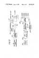
- FIG. 1illustrates, partially in block diagram form and partially in schematic diagram form, an annular array transducer with transmitting and receiving circuitry
- FIG. 2illustrates, in block diagram form, an arrangement for dynamically focussing the ultrasonic echo information received by the arrangement of FIG. 1;
- FIG. 3illustrates, in block diagram form, an aarrangement for producing transmit control signals constructed in accordance with the principles of the present invention
- FIG. 4illustrates, in block diagram form, an arrangement for producing transducer excitation signals for the arrangement of FIG. 1 in accordance with the principles of the present invention
- FIGS. 5 and 6illustrate waveforms depicting the operation of the arrangements of FIGS. 1, 3, and 4.
- an annular array transducer 1is shown connected to its associated transmit and receive circuitry.
- the transducer 1is shown in cross-section, and comprises a hemispherical surface of piezoelectric material mounted on a backing 11.
- the piezoelectric materialis divided into a central disc 10, which is surrounded by three rings 12, 14, and 16.
- Each piezoelectric ringis connected to a respective transmitting circuit, or pulser P 1 -P 4 , and to respective receiving circuits Amp 1 -Amp 4 .
- Pulser P 1 and receiver Amp 1are shown in schematic detail.
- Pulsers P 2 -P 4 and receivers Amp 2 through Amp 4are shown in block diagram form but are constructed in the same manner as pulser P 1 and receiver Amp 1 .
- Pulser P 1receives an excitation signal, labeled TRIG 1 .
- the TRIG 1 signalis applied to one input of a comparator 50, which compares the signal voltage level to a reference voltage, V ref. When the TRIG 1 signal exceeds the V ref voltage, the comparator 50 produces an output signal.
- the comparator 50also serves to electrically isolate the pulser ground level reference voltage from ground level reference voltage of preceding circuitry.
- the output of the comparatoris coupled to the base of a transistor 54 by an R-C network 52.
- the emitter of transistor 54is coupled to ground, and its collector is connected to a current source resistor 56.
- the collector output of the transistor 54is coupled to the input of a power driver 62.
- the power driver 62converts the applied signal to a fifteen volt signal which is applied to the gate of a power FET 64.
- the source of FET 64is connected to ground, and its drain is connected to a storage capacitor 68, over voltage protection zener diodes 58 and 60, and a resistor 66. Current is conducted by resistor 66 from a high voltage source (HV) to charge the capacitor 68 when the FET 64 is not conducting.
- HVhigh voltage source
- the voltage source HVwill have a typical range of 100 to 320 volts DC.
- the FETWhen the FET is pulsed by a TRIG signal, the FET turns on, discharging the capacitor 68 into the center ring 10 of the transducer 1 by way of parallel coupled isolation diodes 72.
- the connecting line to the transducer ringmay also include matching series or parallel chokes, as appropriate for the particular transducer.
- Echo information signals received by the center ring 10 of the transducer 1are applied to the receiver AMP 1 by a coupling capacitor 80 and a shunt choke 82.
- the junction of capacitor 80 and choke 82is connected to series blocking diodes 84 and 86, which protect the receiver from high voltage pulses developed by pulser P 1 .
- a biasing network including series connected resistors 90 and 92is coupled between the joined anodes of diodes 84 and 86 and a +12 volt supply.
- a capacitor 94is coupled between the junction of resistors 90 and 92 and ground.
- the cathode of diode 86is connected to the input winding of a 1:3 step-up transformer 100, and shunt clamping diodes 96 are connected between the cathode of diode 86 and ground.
- the secondary winding of transformer 100is connected by way of a coupling capacitor 102 to the input of a gain controlled amplifier, GCA 1 .
- the output of amplifier GCA 1is coupled to the input of a second gain controlled amplifier GCA 2 .
- Each of these gain controlled amplifiershas a range of -15 db to +15 db which is controlled by a time gain control signal TGC.
- the gain of these two amplifiersmay be varied from -30 db to +30 db as echo signals of decreasing strength are received in response to a transmitted ultrasonic pulse.
- the output of amplifier GCA 2is coupled to the input of an amplifier A 3 , which provides an additional 30 db of gain.
- Amplifier A 3produces an output signal identified as RF 1 .
- excitation signals TRIG 2 , TRIG 3 and TRIG 4activate pulsers P 2 , P 3 , and P 4 for the transmission of ultrasonic energy by respective rings 12, 14 and 16 of the annular array transducer 1. Echo signals received by these rings are applied to respective receivers Amp 2 , Amp 3 , and Amp 4 to produce respective output signals RF 2 , RF 3 , and RF 4 .
- a system for dynamically focussing the received echo signals RF 1 -RF 4is shown in FIG. 2.
- the received echo signalsare applied to an analog multiplexer 20, which steers the appropriate echo signals to a plurality of signal paths including delay lines ⁇ 1 - ⁇ n or through a signal path ⁇ o containing no delay element.
- echoes from a particular point in the tissue being imagedarrive simultaneously at a summing network 30.
- the signalsare combined to produce a composite focussed echo signal at an output.
- the summed signalis then available for log compression and video conversion, then digitization and image display.
- the analog multiplexer 20is controlled by control signals generated in a receiver focus delay control system 40, and applied to the multiplexer 20 by way of control lines 42.
- the receiver focus delay control 40is in turn controlled by information provided on a data bus 210 and an address bus 212, to be described further in conjunction with FIG. 3.
- FIG. 3shows a portion of an arrangement for controlling ultrasonic transmission and reception in accordance with the principles of the present invention.
- the transducer 1 of FIG. 1When the transducer 1 of FIG. 1 is used in a sector scanner, it is desirable to oscillate the transmitted and received ultrasound beams through a plane of tissue. This mechanical oscillation is performed under control of a servocontrol system 202 which controls apparatus to mechanically oscillate the transducer or a beam reflector such as a mirror.
- the servocontrol system 202sends signals to the oscillating apparatus to control the beam motion, and receives feedback signals from the apparatus which are indicative of beam location.
- the servo control systemWhen the transducer or mirror is oriented to properly direct the beam, the servo control system generates a START pulse, which is applied to the clock input C of a data-type flip-flop 126.
- the data input D of flip-flop 126is coupled to a logical one source of supply voltage.
- the flip-flop 126is set by the START signal, causing its Q output to go high which applies a high signal to the D input of a second data-type flip-flop 128.
- a 36 megahertz oscillator 120generates a continuous 36 megahertz clock signal, which is applied to the C input of a further data-type flip-flop 122.
- Flip-flop 122divides the 36 megahertz clock signal by two to produce an 18 megahertz XMT clock signal at its Q output by reason of the coupling of its Q output to its D input.
- the Q output of flip-flop 122is coupled to the C input of flip-flop 128 to set flip-flop 128 in synchronism with the 18 megahertz XMT clock signal.
- the Q output of flip-flop 128produces a one cycle COUNT signal.
- the Q output of flip-flop 128is connected to the reset input R of flip-flop 126 to reset flip-flop 126 when the COUNT signal is generated, which drops the high signal at the D input of flip-flop 128 and terminates the COUNT signal on the next clock cycle.
- the CPU and memory unit 200places data and address information on the data bus 210 and the address bus 212 for the receiver focus delay control 40. This information is tailored specifically for the particular transducer then in use in the system. In response to a depth of focus signal from an operator-controlled joystick control 201, the CPU and memory unit 200 also places transmit control information on the address and data buses. This information is changed whenever the operator adjusts the joystick control for a significantly different depth of focus.
- the data bus 210is connected to a data register 206.
- the address bus 212is coupled to an address decoder 204, which responds to the address information by producing a WRITE signal at its output. The WRITE signal clocks the data in the data register 206, which then holds six waveform control bits WFA1-WFA6.
- the data and control signals generated in the arrangement of FIG. 3are applied to the transmit control arrangement shown in FIG. 4.
- the 18 megahertz XMT clock signalis applied to the clock inputs of counters 130 and 132, latches 144 and 146, and the select inputs of multiplexers 150 and 152.
- the 36 megahertz clock signalis applied to the clock input of a latch 160.
- the waveform address bits WFA1-WFA6are applied to address inputs of programmable read only memories (PROM) 140 and 142 to address selected blocks of memory locations in the PROM's. Using six waveform address bits, 64 different blocks of memory locations, and hence 64 different transmit sequences, may be accessed.
- the COUNT signalis applied to enable inputs of counters 130 and 132.
- the COUNT signaleffectively loads zero counts into the counters which then begin counting in response to the 18 megahertz XMT clock signal.
- the counters 130 and 132are cascaded by a carry out signal from counter 130 into the carry in input of counter 132 to permit the counters to count up from 1 to 32.
- logically high signalsare present on outputs Q A of counter 130 and Q B of counter 132, which are applied to inputs of a NAND gate 134.
- the NAND gate 134is enabled and produces a low signal which is applied to the disable inputs of the counters 130 and 132.
- the counters 130 and 132are thus disabled at this point.
- their Q outputswhich are coupled to further address inputs of PROM's 140 and 142, sequentially address 32 memory locations in the selected block of memory locations.
- the outputs of the PROM'swill produce words from 32 memory locations at an 18 megahertz rate.
- Each PROM output wordis latched into latches 144 and 146 by the 18 megahertz XMT clock.
- the outputs of latches 144 and 146are coupled to inputs of multiplexers 150 and 152, which alternatively select output words from latches 144 and 146 and hence data from the PROM's.
- the multiplexers 150 and 152couple the output word from latch 144 to their outputs.
- the output word stored by latch 146is coupled to the outputs of the multiplexers 150, 152. In this way the 18 megahertz rate of the PROM data is increased to a 36 megahertz rate.
- the six outputs of multiplexers 150 and 152produce separate output signals for six elements or rings of a transducer.
- the six signalsare clocked into a latch 160 by the 36 megahertz clock to produce six output signals which are variable each at a 36 megahertz rate.
- the six output signalsare applied to a buffer 162, which may also provide level translation of the signals to thereby produce six signals TRIG 1 -TRIG 6 for the pulsers of FIG. 1. Since only a four ring transducer 1 is shown in FIG. 1, only signals TRIG 1 -TRIG 4 are required for the embodiment of FIG. 1.
- the hemispherically-shaped face of the annular array transducer 1 of FIG. 1causes the transducer 1 to exhibit a given geometric focus. That is, when all of the rings of the transducer 1 are excited simultaneously, ultrasonic waves will propagate from the transducer rings and will arrive at the geometric focus point simultaneously.
- a 19 mm annular array transducer 1may have a geometric focus point located approximately 10 centimeters from the center ring 10.
- the TRIG signals produced by the arrangement of FIG. 4 and applied to the pulsers P 1 -P 4 of FIG. 1will cause the transmitted ultrasonic waves to be focussed at points beyond or before the geometric focus point in accordance with the timing of the excitation signals.
- the transmitted signalswill first be focussed at short focal distances, and the transmit focus will then be changed to focus the ultrasonic energy at increasing depths in the tissue being imaged.
- the arrangement of FIG. 4will produce TRIG signals as shown in FIG. 5, all referenced to the same horizontal time axis. Since the distance from the outer rings of the transducer 1 to a focal point short of the geometric focus point are greater than the distance from the center ring to the short focus point, the outer rings 16, 14, 12 will be excited prior to center ring 10.
- Each pulser in FIG. 1is activated by a two-pulse TRIG signal sequence as shown in FIG. 5.
- Signal TRIG 4activates pulser P 4 to excite the outer ring 16 first (FIG. 5d).
- signal TRIG 3activates pulser P 3 , which excites ring 14 (FIG. 5c).
- signal TRIG 2activates pulser P 2 to excite ring 12 (FIG. 5b).
- signal TRIG 1activates pulser P 1 to excite the center ring 10 (FIG. 5a).
- the TRIG signals shown in FIG. 5cause the transmitted ultrasonic waves to be focussed at approximately 4 centimeters from the center ring 10.
- the TRIG signalsalso control the frequency of the transmitted ultrasonic waves.
- each pulsehas a duration of approximately 50 nanoseconds, and the period between each pair of pulses, shown as t p , is approximately 200 nanoseconds.
- the 200 nanosecond period between pulsescauses the transmitted ultrasonic energy to have a center frequency of approximately 5 megahertz, a relatively high frequency.
- the relatively high frequencyis desirable for near field focussing, since attenuation of the 5 megahertz signal is relatively small over the short distance and relatively high resolution images result from the high frequency signal.
- TRIG signal waveforms for imaging at approximately 12 centimetersare shown. Since 12 centimeters is beyond the geometric focus of the transducer, the distance from the outer rings of the transducer to the 12 centimeter focal point are shorter than the distance from the center ring to the 12 centimeter focal point. Accordingly, the center ring 10 will be excited prior to excitation of the outer rings so that the propagated waves will arrive at the 12 centimeter focal point concurrently.
- signal TRIG 1activates pulser P 1 to excite the center transducer ring 10.
- signal TRIG 2activates pulser P 2 , which excites outer ring 12 (FIG. 6b).
- Signal TRIG 3activates pulser P 3 20 nanoseconds later (FIG. 6c), and signal TRIG 4 activates pulser P 4 approximately 30 nanoseconds later (FIG. 6d) to excite the outer rings 14 and 16 at these later times, respectively.
- the transmitted signalis focussed at the relatively greater depth of 12 centimeters, a lower transmitted ultrasonic frequency is desired to reduce the effects of attenuation.
- the lower transmitted frequencyis provided by the increased periodicity of the pulse pairs of FIG. 6 relative to those of FIG. 5.
- the period t p between pulses in each of the pulse pairsis approximately 420 nanoseconds, which causes the transmitted ultrasonic energy to exhibit a center frequency of approximately 2.4 megahertz.
- Discrete focal points and corresponding frequency ranges of operationare shown for 3.5 megahertz and 5 megahertz transducers in Table I.
- TRIG signals for each of these focal pointsare stored in separate memory block locations in PROM's 140 and 142 of FIG. 4.
- the nominal 3.5 megahertz transducermay be focussed at distances ranging from 2.0 centimeters to 12.5 centimeters (referenced from the probe exit membrane) with its frequency spectrum changing in a corresponding manner from 5 megahertz to 2.4 megahertz.
- the nominal 5 megahertz transducercan be focussed at distances ranging from 2 to 12 centimeters with its frequency spectrum shifting from 5 megahertz to approximately 3.3 megahertz.
- the trigger signal for the 5 megahertz transduceris a single pulse for the near field focal zones, in order to provide a broad band frequency spectrum for good resolution.
- Data values for these 16 different combinations of focal distance and frequencymay easily be stored in PROM's 140 and 142, which, as discussed above, can store up to 64 such combinations for transducers having up to six elements.
Landscapes
- Physics & Mathematics (AREA)
- Engineering & Computer Science (AREA)
- Acoustics & Sound (AREA)
- Radar, Positioning & Navigation (AREA)
- Remote Sensing (AREA)
- Computer Networks & Wireless Communication (AREA)
- General Physics & Mathematics (AREA)
- Multimedia (AREA)
- Ultra Sonic Daignosis Equipment (AREA)
- Investigating Or Analyzing Materials By The Use Of Ultrasonic Waves (AREA)
- Transducers For Ultrasonic Waves (AREA)
- Measurement Of Velocity Or Position Using Acoustic Or Ultrasonic Waves (AREA)
Abstract
Description
This invention relates to the non-invasive examination of soft tissue and body organs and, in particular, to medical ultrasonic pulse-echo systems for imaging tissue at varying depths in the body.
Ultrasonic diagnostic instruments operate on either a pulse-echo or Doppler principle. The pulse-echo principle is used primarily for the imaging of soft body tissue, and involves the transmission of short bursts of ultrasonic energy into the tissue and the measurement of echoes received from tissue interfaces. The echo measurements are recorded and used to create an image of the tissue which reflected the echoes.
The ultrasonic energy used for imaging is produced by a transducer, which converts electrical energy into acoustic energy for transmission into the tissue being imaged. The transducer may also serve the second function of receiving the reflected echoes. The transducer is typically comprised of a piezoelectric ceramic material which is pulsed to transmit acoustic energy, and which detects received echoes by developing electrical signals in response thereto. The ceramic material may be a single crystal, or may be segmented into an array of elements of various shapes, such as linear and annular arrays.
In order to create a sharply defined tissue image of high resolution and to be able to examine tissue at various depths of field, it is desirable to be able to variably focus the beam of ultrasonic energy which is directed to the tissue, and to focus the echo energy returned from the tissue. In an array-type transducer, this is accomplished by sending time-coordinated bursts of energy from the various elements and by passing the received echoes from different elements through time delays of differing lengths before summing the received signals. Typically, a transmitted beam is directed to one particular range of tissue depths, but echoes may be received from a variety of depths outside the range, and thus the transducer should desirably be dynamically focussed as these echoes return.
The transmitted acoustic energy and returning echoes will undergo attentuation as the ultrasound passes through the tissue. As the depth of field increases and the round trip from the transducer and back again becomes longer, the received echoes will exhibit increasing attenuation. Accordingly, this attenuation is generally compensated for by increasing the gain of the receiver electronics as increasingly more distant echoes are received. This technique of dynamically increasing gain is referred to as time gain control (TGC).
Human tissue is responsible for a further phenomenon during ultrasonic examination. That is the propensity of lower frequency signals to travel through tissue with lesser attenuation than higher frequency signals. In accordance with the principles of the present invention, this phenomenon is advantageously exploited by focussing beams of high frequency acoustic energy in the near field. As the depth of focus is increased from near field focussing to far field focussing under operator control, the frequency of the transmitted ultrasonic energy is automatically reduced correspondingly. Thus, not only is the ultrasonic beam focussed at a desired tissue depth, but the beam is also of appropriate frequency for the selected depth, thereby providing an advantageous compromise of high resolution and good signal-to-noise ratio in the received echoes and resultant tissue image.
In the drawings:
FIG. 1 illustrates, partially in block diagram form and partially in schematic diagram form, an annular array transducer with transmitting and receiving circuitry;
FIG. 2 illustrates, in block diagram form, an arrangement for dynamically focussing the ultrasonic echo information received by the arrangement of FIG. 1;
FIG. 3 illustrates, in block diagram form, an aarrangement for producing transmit control signals constructed in accordance with the principles of the present invention;
FIG. 4 illustrates, in block diagram form, an arrangement for producing transducer excitation signals for the arrangement of FIG. 1 in accordance with the principles of the present invention; and
FIGS. 5 and 6 illustrate waveforms depicting the operation of the arrangements of FIGS. 1, 3, and 4.
Referring to FIG. 1, anannular array transducer 1 is shown connected to its associated transmit and receive circuitry. Thetransducer 1 is shown in cross-section, and comprises a hemispherical surface of piezoelectric material mounted on a backing 11. The piezoelectric material is divided into a central disc 10, which is surrounded by threerings
Pulser P1 receives an excitation signal, labeled TRIG1. The TRIG1 signal is applied to one input of acomparator 50, which compares the signal voltage level to a reference voltage, V ref. When the TRIG1 signal exceeds the V ref voltage, thecomparator 50 produces an output signal. Thecomparator 50 also serves to electrically isolate the pulser ground level reference voltage from ground level reference voltage of preceding circuitry. The output of the comparator is coupled to the base of a transistor 54 by anR-C network 52. The emitter of transistor 54 is coupled to ground, and its collector is connected to a current source resistor 56. The collector output of the transistor 54 is coupled to the input of apower driver 62. Thepower driver 62 converts the applied signal to a fifteen volt signal which is applied to the gate of a power FET 64. The source of FET 64 is connected to ground, and its drain is connected to astorage capacitor 68, over voltage protection zener diodes 58 and 60, and aresistor 66. Current is conducted byresistor 66 from a high voltage source (HV) to charge thecapacitor 68 when the FET 64 is not conducting. The voltage source HV will have a typical range of 100 to 320 volts DC. When the FET is pulsed by a TRIG signal, the FET turns on, discharging thecapacitor 68 into the center ring 10 of thetransducer 1 by way of parallel coupledisolation diodes 72. The connecting line to the transducer ring may also include matching series or parallel chokes, as appropriate for the particular transducer.
Echo information signals received by the center ring 10 of thetransducer 1 are applied to the receiver AMP1 by a coupling capacitor 80 and a shunt choke 82. The junction of capacitor 80 and choke 82 is connected toseries blocking diodes 84 and 86, which protect the receiver from high voltage pulses developed by pulser P1. A biasing network including series connectedresistors 90 and 92 is coupled between the joined anodes ofdiodes 84 and 86 and a +12 volt supply. Acapacitor 94 is coupled between the junction ofresistors 90 and 92 and ground. The cathode ofdiode 86 is connected to the input winding of a 1:3 step-uptransformer 100, andshunt clamping diodes 96 are connected between the cathode ofdiode 86 and ground. The secondary winding oftransformer 100 is connected by way of acoupling capacitor 102 to the input of a gain controlled amplifier, GCA1. The output of amplifier GCA1 is coupled to the input of a second gain controlled amplifier GCA2. Each of these gain controlled amplifiers has a range of -15 db to +15 db which is controlled by a time gain control signal TGC. Thus, the gain of these two amplifiers may be varied from -30 db to +30 db as echo signals of decreasing strength are received in response to a transmitted ultrasonic pulse. The output of amplifier GCA2 is coupled to the input of an amplifier A3, which provides an additional 30 db of gain. Amplifier A3 produces an output signal identified as RF1.
In a similar manner, excitation signals TRIG2, TRIG3 and TRIG4 activate pulsers P2, P3, and P4 for the transmission of ultrasonic energy byrespective rings annular array transducer 1. Echo signals received by these rings are applied to respective receivers Amp2, Amp3, and Amp4 to produce respective output signals RF2, RF3, and RF4.
A system for dynamically focussing the received echo signals RF1 -RF4 is shown in FIG. 2. The received echo signals are applied to ananalog multiplexer 20, which steers the appropriate echo signals to a plurality of signal paths including delay lines τ1 -τn or through a signal path τo containing no delay element. By properly delaying the echo signals as they are continuously received, echoes from a particular point in the tissue being imaged arrive simultaneously at asumming network 30. In thesumming network 30, the signals are combined to produce a composite focussed echo signal at an output. The summed signal is then available for log compression and video conversion, then digitization and image display.
Theanalog multiplexer 20 is controlled by control signals generated in a receiver focusdelay control system 40, and applied to themultiplexer 20 by way of control lines 42. The receiverfocus delay control 40 is in turn controlled by information provided on a data bus 210 and anaddress bus 212, to be described further in conjunction with FIG. 3.
FIG. 3 shows a portion of an arrangement for controlling ultrasonic transmission and reception in accordance with the principles of the present invention. When thetransducer 1 of FIG. 1 is used in a sector scanner, it is desirable to oscillate the transmitted and received ultrasound beams through a plane of tissue. This mechanical oscillation is performed under control of a servocontrol system 202 which controls apparatus to mechanically oscillate the transducer or a beam reflector such as a mirror. The servocontrol system 202 sends signals to the oscillating apparatus to control the beam motion, and receives feedback signals from the apparatus which are indicative of beam location.
When the transducer or mirror is oriented to properly direct the beam, the servo control system generates a START pulse, which is applied to the clock input C of a data-type flip-flop 126. The data input D of flip-flop 126 is coupled to a logical one source of supply voltage. The flip-flop 126 is set by the START signal, causing its Q output to go high which applies a high signal to the D input of a second data-type flip-flop 128. A 36megahertz oscillator 120 generates a continuous 36 megahertz clock signal, which is applied to the C input of a further data-type flip-flop 122. Flip-flop 122 divides the 36 megahertz clock signal by two to produce an 18 megahertz XMT clock signal at its Q output by reason of the coupling of its Q output to its D input. The Q output of flip-flop 122 is coupled to the C input of flip-flop 128 to set flip-flop 128 in synchronism with the 18 megahertz XMT clock signal. The Q output of flip-flop 128 produces a one cycle COUNT signal. The Q output of flip-flop 128 is connected to the reset input R of flip-flop 126 to reset flip-flop 126 when the COUNT signal is generated, which drops the high signal at the D input of flip-flop 128 and terminates the COUNT signal on the next clock cycle.
When the scanning system is initially powered up, the CPU and memory unit 200 places data and address information on the data bus 210 and theaddress bus 212 for the receiverfocus delay control 40. This information is tailored specifically for the particular transducer then in use in the system. In response to a depth of focus signal from an operator-controlled joystick control 201, the CPU and memory unit 200 also places transmit control information on the address and data buses. This information is changed whenever the operator adjusts the joystick control for a significantly different depth of focus. For transmit control, the data bus 210 is connected to a data register 206. Theaddress bus 212 is coupled to anaddress decoder 204, which responds to the address information by producing a WRITE signal at its output. The WRITE signal clocks the data in the data register 206, which then holds six waveform control bits WFA1-WFA6.
The data and control signals generated in the arrangement of FIG. 3 are applied to the transmit control arrangement shown in FIG. 4. The 18 megahertz XMT clock signal is applied to the clock inputs ofcounters 130 and 132, latches 144 and 146, and the select inputs ofmultiplexers latch 160. The waveform address bits WFA1-WFA6 are applied to address inputs of programmable read only memories (PROM) 140 and 142 to address selected blocks of memory locations in the PROM's. Using six waveform address bits, 64 different blocks of memory locations, and hence 64 different transmit sequences, may be accessed.
With the waveform address bits WFA1-WFA6 addressing a selected block of PROM memory, the COUNT signal is applied to enable inputs ofcounters 130 and 132. The COUNT signal effectively loads zero counts into the counters which then begin counting in response to the 18 megahertz XMT clock signal. Thecounters 130 and 132 are cascaded by a carry out signal from counter 130 into the carry in input ofcounter 132 to permit the counters to count up from 1 to 32. At the count of 33, logically high signals are present on outputs QA of counter 130 and QB ofcounter 132, which are applied to inputs of aNAND gate 134. At the count of 33, theNAND gate 134 is enabled and produces a low signal which is applied to the disable inputs of thecounters 130 and 132. Thecounters 130 and 132 are thus disabled at this point. As the counters are counting, their Q outputs, which are coupled to further address inputs of PROM's 140 and 142, sequentially address 32 memory locations in the selected block of memory locations. Thus, the outputs of the PROM's will produce words from 32 memory locations at an 18 megahertz rate.
Each PROM output word is latched intolatches latches multiplexers latches multiplexers latch 144 to their outputs. During the next half cycle of the 18 megahertz XMT clock, the output word stored bylatch 146 is coupled to the outputs of themultiplexers
The six outputs ofmultiplexers latch 160 by the 36 megahertz clock to produce six output signals which are variable each at a 36 megahertz rate. The six output signals are applied to abuffer 162, which may also provide level translation of the signals to thereby produce six signals TRIG1 -TRIG6 for the pulsers of FIG. 1. Since only a fourring transducer 1 is shown in FIG. 1, only signals TRIG1 -TRIG4 are required for the embodiment of FIG. 1.
The hemispherically-shaped face of theannular array transducer 1 of FIG. 1 causes thetransducer 1 to exhibit a given geometric focus. That is, when all of the rings of thetransducer 1 are excited simultaneously, ultrasonic waves will propagate from the transducer rings and will arrive at the geometric focus point simultaneously. For example, a 19 mmannular array transducer 1 may have a geometric focus point located approximately 10 centimeters from the center ring 10.
The TRIG signals produced by the arrangement of FIG. 4 and applied to the pulsers P1 -P4 of FIG. 1 will cause the transmitted ultrasonic waves to be focussed at points beyond or before the geometric focus point in accordance with the timing of the excitation signals. In a typical sequence of operation, the transmitted signals will first be focussed at short focal distances, and the transmit focus will then be changed to focus the ultrasonic energy at increasing depths in the tissue being imaged. When it is desired to focus the energy at a short depth, such as 4 centimeters, the arrangement of FIG. 4 will produce TRIG signals as shown in FIG. 5, all referenced to the same horizontal time axis. Since the distance from the outer rings of thetransducer 1 to a focal point short of the geometric focus point are greater than the distance from the center ring to the short focus point, the outer rings 16, 14, 12 will be excited prior to center ring 10.
Each pulser in FIG. 1 is activated by a two-pulse TRIG signal sequence as shown in FIG. 5. Signal TRIG4 activates pulser P4 to excite theouter ring 16 first (FIG. 5d). Approximately 80 nanoseconds later, signal TRIG3 activates pulser P3, which excites ring 14 (FIG. 5c). Approximately 45 nanoseconds later, signal TRIG2 activates pulser P2 to excite ring 12 (FIG. 5b). Finally, approximately 75 nanoseconds later, signal TRIG1 activates pulser P1 to excite the center ring 10 (FIG. 5a). In this manner, the TRIG signals shown in FIG. 5 cause the transmitted ultrasonic waves to be focussed at approximately 4 centimeters from the center ring 10.
In accordance with the principles of the present invention, the TRIG signals also control the frequency of the transmitted ultrasonic waves. In FIG. 5, each pulse has a duration of approximately 50 nanoseconds, and the period between each pair of pulses, shown as tp, is approximately 200 nanoseconds. The 200 nanosecond period between pulses causes the transmitted ultrasonic energy to have a center frequency of approximately 5 megahertz, a relatively high frequency. The relatively high frequency is desirable for near field focussing, since attenuation of the 5 megahertz signal is relatively small over the short distance and relatively high resolution images result from the high frequency signal.
As the focal distance of the transducer is changed by the operator, the frequency of the transmitted signal is also changed correspondingly for improved attenuation characteristics at these different focal depths. Referring to FIG. 6, TRIG signal waveforms for imaging at approximately 12 centimeters are shown. Since 12 centimeters is beyond the geometric focus of the transducer, the distance from the outer rings of the transducer to the 12 centimeter focal point are shorter than the distance from the center ring to the 12 centimeter focal point. Accordingly, the center ring 10 will be excited prior to excitation of the outer rings so that the propagated waves will arrive at the 12 centimeter focal point concurrently. In FIG. 6a, signal TRIG1 activates pulser P1 to excite the center transducer ring 10. Approximately 20 nanoseconds later, signal TRIG2 activates pulser P2, which excites outer ring 12 (FIG. 6b). Signal TRIG3 activatespulser P 3 20 nanoseconds later (FIG. 6c), and signal TRIG4 activates pulser P4 approximately 30 nanoseconds later (FIG. 6d) to excite theouter rings
Since the transmitted signal is focussed at the relatively greater depth of 12 centimeters, a lower transmitted ultrasonic frequency is desired to reduce the effects of attenuation. The lower transmitted frequency is provided by the increased periodicity of the pulse pairs of FIG. 6 relative to those of FIG. 5. In FIG. 6, the period tp between pulses in each of the pulse pairs is approximately 420 nanoseconds, which causes the transmitted ultrasonic energy to exhibit a center frequency of approximately 2.4 megahertz.
Discrete focal points and corresponding frequency ranges of operation are shown for 3.5 megahertz and 5 megahertz transducers in Table I. TRIG signals for each of these focal points are stored in separate memory block locations in PROM's 140 and 142 of FIG. 4. The nominal 3.5 megahertz transducer may be focussed at distances ranging from 2.0 centimeters to 12.5 centimeters (referenced from the probe exit membrane) with its frequency spectrum changing in a corresponding manner from 5 megahertz to 2.4 megahertz. Similarly, the nominal 5 megahertz transducer can be focussed at distances ranging from 2 to 12 centimeters with its frequency spectrum shifting from 5 megahertz to approximately 3.3 megahertz. The trigger signal for the 5 megahertz transducer is a single pulse for the near field focal zones, in order to provide a broad band frequency spectrum for good resolution. Data values for these 16 different combinations of focal distance and frequency may easily be stored in PROM's 140 and 142, which, as discussed above, can store up to 64 such combinations for transducers having up to six elements.
TABLE I ______________________________________ 3.5 MHz Tranducer 5 MHz Transducer Depth, cm. Freq., MHz. Depth, cm. Freq., MHz ______________________________________ 2.0 5 2 Broad band, single pulse 3.0 ↑ 3 Broad band, single pulse 4.0 ↑ 4.0 Broad band, single pulse 5.0 ↑ 5.0 Broad band, single pulse 6.5 ↓ 6.5 5.0, double pulse 8.5 ↓ 8.0 ↑, double pulse 10.5 ↓ 10.0 ↓, double pulse 12.5 2.5 12.0 3.3, double pulse ______________________________________
Claims (13)
1. In an ultrasonic diagnostic imaging system, including an annular array transducer of concentric piezoelectric elements for transmitting ultrasonic energy into tissue to be imaged and for receiving echoes from said tissue; apparatus comprising:
a plurality of transducer pulsers, each having an output coupled to a respective element of said transducer for exciting said elements, and having respective inputs; and
means, coupled to said inputs of said pulsers, for selecting from a plurality of predetermined activating signals, a time sequence of activating signals for a single transmit period which focuses the energy transmitted by ones of said elements at a given tissue depth, said selected signals exhibiting one of a plurality of predetermined characteristic waveforms for exciting said elements at one of a plurality of transmission frequencies, which frequency is variable as a function of said tissue depth,
wherein said selected activating signals are applied to respective ones of said pulser inputs.
2. In an ultrasonic diagnostic imaging system, including an annular array transducer of concentric piezoelectric elements for transmitting ultrasonic energy into tissue to be imaged and for receiving echoes from said tissue; apparatus comprising:
memory means for storing transmit control signals corresponding to a plurality of different focal depths and corresponding transmission frequencies; and
means, having an input coupled to said memory means and outputs coupled to respective ones of said elements of said transducer, and responsive to said transmit control signals for exciting said elements in one of a plurality of time sequences which focuses energy transmitted by said elements at a given one of said focal depths, and for exciting said elements with one of a plurality of predetermined waveforms to transmit energy at the frequency corresponding to said given focal depth.
3. In an ultrasonic diagnostic imaging system, including an annular array transducer of concentric piezoelectric elements for transmitting ultrasonic energy into tissue to be imaged and for receiving echoes from said tissue; apparatus comprising:
a plurality of transducer pulsers, each having an output coupled to a respective element of said transducer for exciting said elements, and having respective inputs;
means, coupled to said inputs of said pulsers, for selectively activating said pulsers in one of a plurality of time sequences so as to focus the energy transmitted by said elements at a given tissue depth;
control means, coupled to said selectively activating means, for selecting said one time sequence corresponding to said given tissue depth; and
means, coupled to said control means and to said inputs of said pulsers, and responsive to the selection of said one time sequence, for exciting said elements at one of a plurality of transmission frequencies corresponding to said given tissue depth.
4. In an ultrasonic diagnostic imaging system, including an annular array transducer of concentric piezoelectric elements for transmitting ultrasonic energy into tissue to be imaged and for receiving echoes from said tissue; apparatus comprising:
a plurality of transducer pulsers, each having an output coupled to a respective element of said transducer for exciting said elements, and having respective inputs;
means, coupled to the inputs of said pulsers, for activating said pulsers in one of a plurality of time sequences corresponding to different tissue focal depths, and for exciting said elements at one of a variety of different transmission center frequencies; and
selection means, coupled to said means for activating and exciting, for selecting one of said time sequences and a corresponding transmission center frequency;
wherein the transmission center frequency at the maximum tissue focal depth is lower than the transmission center frequency at the minimum tissue focal depth.
5. In an ultrasonic diagnostic imaging system, including an annular array transducer of concentric piezoelectric elements for transmitting ultrasonic energy into tissue to be imaged and for receiving echoes from said tissue; apparatus comprising:
a memory for storing blocks of data, each block including a plurality of data streams and each data stream comprising a sequence of one or more pulses which may be read from the memory in a given time relationship to the other data streams in the same data block;
means for selecting a given depth of focus in said tissue to be imaged over a range of focal depths;
a central processing unit, coupled to said selecting means, for addressing a given one of said data blocks of said memory;
means for simultaneously reading out said data streams of said addressed data block; and
a plurality of transducer pulsers, each having an input coupled to receive a respective one of said data streams of said addressed data block, and respective outputs coupled to respective ones of said elements of said transducer, for focussing said transducer in accordance with the time relationship of said pulses and for exciting said elements into ultrasonic transmission at a selected frequency of a plurality of frequencies determined by the repetition rate of said pulses in said data streams,
wherein different depths of focus have different corresponding transmission frequencies.
6. The arrangement of claim 5, wherein said pulsers each include a power FET for driving a transducer element.
7. In an ultrasonic diagnostic system, including a multi-element transducer for transmitting ultrasonic energy into tissue to be imaged and for receiving echoes from said tissue; apparatus comprising:
a memory for storing blocks of data, each block including a plurality of data streams and each data stream comprising a sequence of one or more pulses which may be read from the memory in a given time relationship to the other data streams in the same data block;
means for selecting a given depth of focus in said tissue to be imaged over a range of focal depths;
a central processing unit, coupled to said selecting means, for addressing a given one of said data blocks of said memory;
means for simultaneously reading out said data streams of said addressed data block; and
a plurality of transducer pulsers, each having an input coupled to receive a respective one of said data streams of said addressed data block, and respective outputs coupled to respective ones of said elements of said transducer, for focussing said transducer in accordance with the time relationship of said pulses and for exciting said elements into ultrasonic transmission at frequencies determined by the repetition rate of said pulses in respective ones of said data streams,
wherein different depths of focus have different transmission frequencies; said pulsers each include a power FET for driving a transducer element; and
wherein said memory includes first and second PROM's having outputs coupled to a multiplexer for alternately producing data from said PROM's at the outputs of said multiplexer,
wherein the data streams produced by said multiplexeer exhibit a bandwidth which is twice the bandwidth of data streams produced by said respective PROM's.
8. In an ultrasonic diagnostic imaging system, including a multi-element transducer for transmitting ultrasonic energy into tissue to be imaged and for receiving echoes from said tissue; apparatus comprising:
a memory for storing blocks of data, each block including a plurality of data streams and each data stream comprising a sequence of one or more pulses which may be read from the memory in a given time relationship to the other data streams in the same data block;
means for selecting a given depth of focus in said tissue to be imaged over a range of focal depths;
a central processing unit, coupled to said selecting means, for addressing a given one of said data blocks of said memory;
means for simultaneously reading out said data streams of said addressed data block; and
a plurality of transducer pulsers, each having an input coupled to receive a respective one of said data streams of said addressed data block, and respective outputs coupled to respective ones of said elements of said transducer, for focussing said transducer in accordance with the time relationship of said pulses and for exciting said elements into ultrasonic transmission at frequencies determined by the repetition rate of said pulses in respective ones of said data streams,
wherein different depths of focus have different transmission frequencies; said pulsers each include a power FET for driving a transducer element; and
wherein said memory includes first and second PROM's having outputs coupled to a multiplexer for alternately producing data from said PROM's at the outputs of said multiplexer,
wherein the data streams produced by said multiplexer exhibit a bandwidth which is twice the bandwidth of data streams produced by said respective PROM's; and
further comprising:
a first source of clock signals at a first frequency;
a second source of clock signals at a frequency which is half said first frequency;
means for applying said second clock signals to said PROM's and said multiplexer;
a latch stage having outputs, and inputs coupled to the outputs of said multiplexer;
means for applying said first clock signals to said latch stage; and
means for coupling the outputs of said latch stage to the inputs of said pulsers.
9. In an ultrasonic diagnostic imaging system, including a multi-element transducer for transmitting ultrasonic energy into tissue to be imaged and for receiving echoes from said tissue; apparatus comprising:
a plurality of transducer pulsers, each having an output coupled to a respective element of said transducer for exciting said elements, and having respective inputs;
means for selecting a given depth of focus within said tissue to be imaged from a range of focal depths by controlling the time sequence of pulsing of the respective elements; and
means, responsive to said selecting means, for activating said pulsers to produce broad band ultrasonic energy transmission by said transducer elements when one depth of focus is selected, and to produce narrow band ultrasonic energy transmission by said transducer elements when a different depth of focus is selected.
10. The arrangement of claim 9, wherein the spectrum of said narrow band energy transmission is centered around one of a plurality of different center frequencies.
11. The arrangement of claim 10, wherein said activating means applies a single pulse to respective ones of said pulsers when near field focusing is selected, and a plurality of pulses to respective ones of said pulsers when far field focusing is selected.
12. The arrangement of claim 11, wherein said center frequencies are determined as a function of the periodicity of said plurality of pulses.
13. In an ultrasonic diagnostic imaging system, including an annular array transducer of concentric piezoelectric elements for transmitting ultrasonic energy into tissue to be imaged and for receiving echoes from said tissue; apparatus comprising:
means for selecting a given depth of transmit focus from a range of focal depths;
means, responsive to said selection of said given depth, and coupled to said elements of said transducer, for activating said elements in one of a plurality of time sequences so as to focus said transmitted energy at said selected depth;
means, responsive to said selection of said given depth, and coupled to said elements of said transducer, for causing said transmitted energy to exhibit one of a plurality of respectively different frequency characteristics which are variable as a function of the depth of transmit focus; and
means, coupled to said transducer elements, for dynamically focusing the received echo information.
Applications Claiming Priority (2)
| Application Number | Priority Date | Filing Date | Title |
|---|---|---|---|
| GB8227532 | 1982-09-27 | ||
| GB8227532 | 1982-09-27 |
Publications (1)
| Publication Number | Publication Date |
|---|---|
| US4534221Atrue US4534221A (en) | 1985-08-13 |
Family
ID=10533191
Family Applications (1)
| Application Number | Title | Priority Date | Filing Date |
|---|---|---|---|
| US06/451,313Expired - LifetimeUS4534221A (en) | 1982-09-27 | 1982-12-20 | Ultrasonic diagnostic imaging systems for varying depths of field |
Country Status (8)
| Country | Link |
|---|---|
| US (1) | US4534221A (en) |
| EP (2) | EP0104929B1 (en) |
| JP (4) | JPS5980098A (en) |
| AU (2) | AU572795B2 (en) |
| CA (2) | CA1213355A (en) |
| DE (2) | DE3381056D1 (en) |
| ES (2) | ES525959A0 (en) |
| HK (2) | HK38390A (en) |
Cited By (92)
| Publication number | Priority date | Publication date | Assignee | Title |
|---|---|---|---|---|
| US4574635A (en)* | 1984-11-02 | 1986-03-11 | North American Philips Corporation | Monitoring of frequency shift of ultrasound pulses in tissue |
| US4788981A (en)* | 1986-10-16 | 1988-12-06 | Olympus Optical Co., Ltd. | Pulse compression apparatus for ultrasonic image processing |
| US4888746A (en)* | 1987-09-24 | 1989-12-19 | Richard Wolf Gmbh | Focussing ultrasound transducer |
| US4993416A (en)* | 1989-04-25 | 1991-02-19 | Board Of Reagents The University Of Texas System | System for ultrasonic pan focal imaging and axial beam translation |
| US5014712A (en)* | 1989-12-26 | 1991-05-14 | General Electric Company | Coded excitation for transmission dynamic focusing of vibratory energy beam |
| US5024094A (en)* | 1987-12-15 | 1991-06-18 | Hitaci, Ltd. | Ultrasonic imaging system of bonding zone |
| US5072735A (en)* | 1988-06-21 | 1991-12-17 | Kabushiki Kaisha Toshiba | Ultrasonic imaging apparatus |
| US5199299A (en)* | 1991-03-11 | 1993-04-06 | Iowa State University Research Foundation, Inc. | Ultrasonic unipolar pulse/echo instrument |
| US5226847A (en)* | 1989-12-15 | 1993-07-13 | General Electric Company | Apparatus and method for acquiring imaging signals with reduced number of interconnect wires |
| US5271403A (en)* | 1991-09-05 | 1993-12-21 | Paulos John J | Ultrasound imaging system |
| US5301674A (en)* | 1992-03-27 | 1994-04-12 | Diasonics, Inc. | Method and apparatus for focusing transmission and reception of ultrasonic beams |
| US5316000A (en)* | 1991-03-05 | 1994-05-31 | Technomed International (Societe Anonyme) | Use of at least one composite piezoelectric transducer in the manufacture of an ultrasonic therapy apparatus for applying therapy, in a body zone, in particular to concretions, to tissue, or to bones, of a living being and method of ultrasonic therapy |
| US5379642A (en)* | 1993-07-19 | 1995-01-10 | Diasonics Ultrasound, Inc. | Method and apparatus for performing imaging |
| US5383465A (en)* | 1989-12-18 | 1995-01-24 | Lesny; Jan | Ultrasonic instrument |
| US5415175A (en)* | 1993-09-07 | 1995-05-16 | Acuson Corporation | Broadband phased array transducer design with frequency controlled two dimension capability and methods for manufacture thereof |
| US5438998A (en)* | 1993-09-07 | 1995-08-08 | Acuson Corporation | Broadband phased array transducer design with frequency controlled two dimension capability and methods for manufacture thereof |
| US5482045A (en)* | 1994-10-12 | 1996-01-09 | Advanced Technology Laboratories, Inc. | Ultrasonic diagnostic system gain control |
| WO1996004589A1 (en)* | 1994-08-05 | 1996-02-15 | Acuson Corporation | Method and apparatus for transmit beamformer system |
| US5549111A (en)* | 1994-08-05 | 1996-08-27 | Acuson Corporation | Method and apparatus for adjustable frequency scanning in ultrasound imaging |
| US5675554A (en)* | 1994-08-05 | 1997-10-07 | Acuson Corporation | Method and apparatus for transmit beamformer |
| US5678554A (en)* | 1996-07-02 | 1997-10-21 | Acuson Corporation | Ultrasound transducer for multiple focusing and method for manufacture thereof |
| US5690113A (en)* | 1996-06-14 | 1997-11-25 | Acuson Corporation | Method and apparatus for two dimensional ultrasonic imaging |
| AU688334B2 (en)* | 1993-09-07 | 1998-03-12 | Siemens Medical Solutions Usa, Inc. | Broadband phased array transducer design with frequency controlled two dimension capability and methods for manufacture thereof |
| US5743855A (en)* | 1995-03-03 | 1998-04-28 | Acuson Corporation | Broadband phased array transducer design with frequency controlled two dimension capability and methods for manufacture thereof |
| US5957852A (en)* | 1998-06-02 | 1999-09-28 | Acuson Corporation | Ultrasonic harmonic imaging system and method |
| US6027448A (en)* | 1995-03-02 | 2000-02-22 | Acuson Corporation | Ultrasonic transducer and method for harmonic imaging |
| US6048316A (en)* | 1998-10-16 | 2000-04-11 | Acuson Corporation | Medical diagnostic ultrasonic imaging system and method for displaying composite fundamental and harmonic images |
| US6116244A (en)* | 1998-06-02 | 2000-09-12 | Acuson Corporation | Ultrasonic system and method for three-dimensional imaging with opacity control |
| US6122538A (en)* | 1997-01-16 | 2000-09-19 | Acuson Corporation | Motion--Monitoring method and system for medical devices |
| US6132374A (en)* | 1997-08-01 | 2000-10-17 | Acuson Corporation | Ultrasonic imaging method and system |
| US6503200B2 (en)* | 2000-03-28 | 2003-01-07 | Matsushita Electric Industrial Co., Ltd. | Ultrasonic diagnostic apparatus |
| US20030220554A1 (en)* | 2002-05-23 | 2003-11-27 | Volumetrics Medical Imaging, Inc. | Two-dimensional ultrasonic array with asymmetric apertures |
| US6755787B2 (en) | 1998-06-02 | 2004-06-29 | Acuson Corporation | Medical diagnostic ultrasound system and method for versatile processing |
| US20050240103A1 (en)* | 2004-04-20 | 2005-10-27 | Ep Medsystems, Inc. | Method and apparatus for ultrasound imaging with autofrequency selection |
| US20060016262A1 (en)* | 2004-07-20 | 2006-01-26 | Denso Corporation | Obstacle detection system |
| US20060058677A1 (en)* | 2002-04-26 | 2006-03-16 | Kazutaka Okada | Ultrasonograph |
| US20060253028A1 (en)* | 2005-04-20 | 2006-11-09 | Scimed Life Systems, Inc. | Multiple transducer configurations for medical ultrasound imaging |
| US20060254359A1 (en)* | 2005-01-14 | 2006-11-16 | Pierre Langlois | Hand-held flaw detector imaging apparatus |
| US20070276252A1 (en)* | 2006-05-04 | 2007-11-29 | William Kolasa | Multiple frequency doppler ultrasound probe |
| US20080221491A1 (en)* | 2004-09-16 | 2008-09-11 | Guided Therapy Systems, Inc. | Method and system for combined energy therapy profile |
| US20080269610A1 (en)* | 2007-04-25 | 2008-10-30 | General Electric Company | Method and apparatus for automatic optimization of scanning parameters for ultrasound imaging |
| US20080294073A1 (en)* | 2006-09-18 | 2008-11-27 | Guided Therapy Systems, Inc. | Method and sysem for non-ablative acne treatment and prevention |
| CN100475153C (en)* | 2006-07-31 | 2009-04-08 | 深圳市德力凯电子有限公司 | A Broadband Transcranial Doppler System |
| US20090216159A1 (en)* | 2004-09-24 | 2009-08-27 | Slayton Michael H | Method and system for combined ultrasound treatment |
| US20090253988A1 (en)* | 2004-10-06 | 2009-10-08 | Slayton Michael H | Method and system for noninvasive mastopexy |
| US20090281463A1 (en)* | 2006-07-05 | 2009-11-12 | Edap S.A. | Therapy apparatus with sequential functioning |
| US20100031750A1 (en)* | 2008-08-05 | 2010-02-11 | Roger Spencer | Ut method of identifying a stuck joint |
| US20100106011A1 (en)* | 2004-11-23 | 2010-04-29 | Charles Bryan Byrd | Method and apparatus for localizing an ultrasound catheter |
| US20100160782A1 (en)* | 2004-10-06 | 2010-06-24 | Guided Therapy Systems, Llc | Methods and systems for fat reduction and/or cellulite treatment |
| WO2013184798A1 (en)* | 2012-06-07 | 2013-12-12 | Ulthera, Inc. | Devices and methods for ultrasound focal depth control |
| US8636665B2 (en) | 2004-10-06 | 2014-01-28 | Guided Therapy Systems, Llc | Method and system for ultrasound treatment of fat |
| US8690778B2 (en) | 2004-10-06 | 2014-04-08 | Guided Therapy Systems, Llc | Energy-based tissue tightening |
| US8690780B2 (en) | 2004-10-06 | 2014-04-08 | Guided Therapy Systems, Llc | Noninvasive tissue tightening for cosmetic effects |
| US8858471B2 (en) | 2011-07-10 | 2014-10-14 | Guided Therapy Systems, Llc | Methods and systems for ultrasound treatment |
| US8857438B2 (en) | 2010-11-08 | 2014-10-14 | Ulthera, Inc. | Devices and methods for acoustic shielding |
| US8868958B2 (en) | 2005-04-25 | 2014-10-21 | Ardent Sound, Inc | Method and system for enhancing computer peripheral safety |
| US8915870B2 (en) | 2004-10-06 | 2014-12-23 | Guided Therapy Systems, Llc | Method and system for treating stretch marks |
| US8915853B2 (en) | 2004-10-06 | 2014-12-23 | Guided Therapy Systems, Llc | Methods for face and neck lifts |
| US8932224B2 (en) | 2004-10-06 | 2015-01-13 | Guided Therapy Systems, Llc | Energy based hyperhidrosis treatment |
| US9011337B2 (en) | 2011-07-11 | 2015-04-21 | Guided Therapy Systems, Llc | Systems and methods for monitoring and controlling ultrasound power output and stability |
| US9039617B2 (en) | 2009-11-24 | 2015-05-26 | Guided Therapy Systems, Llc | Methods and systems for generating thermal bubbles for improved ultrasound imaging and therapy |
| US9063059B2 (en) | 2011-05-10 | 2015-06-23 | Edison Welding Institute, Inc. | Three-dimensional matrix phased array spot weld inspection system |
| US9114247B2 (en) | 2004-09-16 | 2015-08-25 | Guided Therapy Systems, Llc | Method and system for ultrasound treatment with a multi-directional transducer |
| US9149658B2 (en) | 2010-08-02 | 2015-10-06 | Guided Therapy Systems, Llc | Systems and methods for ultrasound treatment |
| US9216276B2 (en) | 2007-05-07 | 2015-12-22 | Guided Therapy Systems, Llc | Methods and systems for modulating medicants using acoustic energy |
| US9263663B2 (en) | 2012-04-13 | 2016-02-16 | Ardent Sound, Inc. | Method of making thick film transducer arrays |
| US9272162B2 (en) | 1997-10-14 | 2016-03-01 | Guided Therapy Systems, Llc | Imaging, therapy, and temperature monitoring ultrasonic method |
| US9320537B2 (en) | 2004-10-06 | 2016-04-26 | Guided Therapy Systems, Llc | Methods for noninvasive skin tightening |
| US20160231291A1 (en)* | 2011-05-10 | 2016-08-11 | Edison Welding Institute, Inc. | Gating methods for use in weld inspection systems |
| US9504446B2 (en) | 2010-08-02 | 2016-11-29 | Guided Therapy Systems, Llc | Systems and methods for coupling an ultrasound source to tissue |
| US9510802B2 (en) | 2012-09-21 | 2016-12-06 | Guided Therapy Systems, Llc | Reflective ultrasound technology for dermatological treatments |
| US9694212B2 (en) | 2004-10-06 | 2017-07-04 | Guided Therapy Systems, Llc | Method and system for ultrasound treatment of skin |
| US9700340B2 (en) | 2004-10-06 | 2017-07-11 | Guided Therapy Systems, Llc | System and method for ultra-high frequency ultrasound treatment |
| US9827449B2 (en) | 2004-10-06 | 2017-11-28 | Guided Therapy Systems, L.L.C. | Systems for treating skin laxity |
| US9907535B2 (en) | 2000-12-28 | 2018-03-06 | Ardent Sound, Inc. | Visual imaging system for ultrasonic probe |
| US10039938B2 (en) | 2004-09-16 | 2018-08-07 | Guided Therapy Systems, Llc | System and method for variable depth ultrasound treatment |
| US10420960B2 (en) | 2013-03-08 | 2019-09-24 | Ulthera, Inc. | Devices and methods for multi-focus ultrasound therapy |
| US10537304B2 (en) | 2008-06-06 | 2020-01-21 | Ulthera, Inc. | Hand wand for ultrasonic cosmetic treatment and imaging |
| US10561862B2 (en) | 2013-03-15 | 2020-02-18 | Guided Therapy Systems, Llc | Ultrasound treatment device and methods of use |
| US10603521B2 (en) | 2014-04-18 | 2020-03-31 | Ulthera, Inc. | Band transducer ultrasound therapy |
| US10864385B2 (en) | 2004-09-24 | 2020-12-15 | Guided Therapy Systems, Llc | Rejuvenating skin by heating tissue for cosmetic treatment of the face and body |
| US11207548B2 (en) | 2004-10-07 | 2021-12-28 | Guided Therapy Systems, L.L.C. | Ultrasound probe for treating skin laxity |
| US11224895B2 (en) | 2016-01-18 | 2022-01-18 | Ulthera, Inc. | Compact ultrasound device having annular ultrasound array peripherally electrically connected to flexible printed circuit board and method of assembly thereof |
| US11235179B2 (en) | 2004-10-06 | 2022-02-01 | Guided Therapy Systems, Llc | Energy based skin gland treatment |
| US11241218B2 (en) | 2016-08-16 | 2022-02-08 | Ulthera, Inc. | Systems and methods for cosmetic ultrasound treatment of skin |
| US11717661B2 (en) | 2007-05-07 | 2023-08-08 | Guided Therapy Systems, Llc | Methods and systems for ultrasound assisted delivery of a medicant to tissue |
| US11724133B2 (en) | 2004-10-07 | 2023-08-15 | Guided Therapy Systems, Llc | Ultrasound probe for treatment of skin |
| US11883688B2 (en) | 2004-10-06 | 2024-01-30 | Guided Therapy Systems, Llc | Energy based fat reduction |
| US11944849B2 (en) | 2018-02-20 | 2024-04-02 | Ulthera, Inc. | Systems and methods for combined cosmetic treatment of cellulite with ultrasound |
| US12076591B2 (en) | 2018-01-26 | 2024-09-03 | Ulthera, Inc. | Systems and methods for simultaneous multi-focus ultrasound therapy in multiple dimensions |
| US12102473B2 (en) | 2008-06-06 | 2024-10-01 | Ulthera, Inc. | Systems for ultrasound treatment |
| US12377293B2 (en) | 2019-07-15 | 2025-08-05 | Ulthera, Inc. | Systems and methods for measuring elasticity with imaging of ultrasound multi-focus shearwaves in multiple dimensions |
Families Citing this family (16)
| Publication number | Priority date | Publication date | Assignee | Title |
|---|---|---|---|---|
| US4534221A (en)* | 1982-09-27 | 1985-08-13 | Technicare Corporation | Ultrasonic diagnostic imaging systems for varying depths of field |
| JPS62170233A (en)* | 1986-01-22 | 1987-07-27 | 株式会社島津製作所 | Transducer excitation drive method |
| DE3663860D1 (en)* | 1986-12-24 | 1989-07-13 | Hewlett Packard Gmbh | Method of and apparatus for adjusting the intensity profile of an ultrasound beam |
| JPH0722578B2 (en)* | 1988-12-09 | 1995-03-15 | 松下電器産業株式会社 | Ultrasonic probe |
| JPH02234600A (en)* | 1989-03-07 | 1990-09-17 | Mitsubishi Mining & Cement Co Ltd | Piezoelectric conversion element |
| JPH03176040A (en)* | 1989-09-29 | 1991-07-31 | Terumo Corp | Ultrasonic diagnostic apparatus |
| US5113706A (en)* | 1990-07-03 | 1992-05-19 | Hewlett-Packard Company | Ultrasound system with dynamic transmit focus |
| JPH04300530A (en)* | 1991-03-29 | 1992-10-23 | Shimadzu Corp | Ultrasound diagnostic equipment |
| US5368054A (en)* | 1993-12-17 | 1994-11-29 | International Business Machines Corporation | Ultrasonic jet semiconductor wafer cleaning apparatus |
| JPH06339302A (en)* | 1994-06-02 | 1994-12-13 | Iseki & Co Ltd | Hydraulic lifting control device for tractor |
| DE4446429C1 (en)* | 1994-12-23 | 1996-08-22 | Siemens Ag | Device for treating an object with focused ultrasound waves |
| US20090171217A1 (en)* | 2007-12-27 | 2009-07-02 | Jeong Hwan Kim | Ultrasound system for diagnosing breast cancer |
| JP5892745B2 (en)* | 2011-08-18 | 2016-03-23 | 株式会社東芝 | Ultrasonic diagnostic equipment |
| JP6457107B2 (en)* | 2015-10-22 | 2019-01-23 | 株式会社日立製作所 | Ultrasonic diagnostic apparatus and attenuation characteristic measuring method |
| CN105591020B (en)* | 2016-03-07 | 2017-12-08 | 华中科技大学 | A kind of high-frequency transducer with curve focusing array and preparation method thereof |
| RU2755594C1 (en)* | 2020-10-27 | 2021-09-17 | Федеральное государственное автономное образовательное учреждение высшего образования "Санкт-Петербургский государственный электротехнический университет "ЛЭТИ" им. В.И. Ульянова (Ленина) | Device for measuring geometric parameters of three-dimensional image of objects made of sound-reflecting materials |
Citations (25)
| Publication number | Priority date | Publication date | Assignee | Title |
|---|---|---|---|---|
| US3815409A (en)* | 1973-02-15 | 1974-06-11 | A Macovski | Focused sonic imaging system |
| US3898840A (en)* | 1974-01-30 | 1975-08-12 | Automation Ind Inc | Multi-frequency ultrasonic search unit |
| US3924454A (en)* | 1973-10-24 | 1975-12-09 | Automation Ind Inc | Multi-frequency ultrasonic testing system |
| US4016751A (en)* | 1973-09-13 | 1977-04-12 | The Commonwealth Of Australia Care Of The Department Of Health | Ultrasonic beam forming technique |
| US4016750A (en)* | 1975-11-06 | 1977-04-12 | Stanford Research Institute | Ultrasonic imaging method and apparatus |
| US4034332A (en)* | 1974-10-15 | 1977-07-05 | Agence Nationale De Valorisation De La Recherche (Anvar) | Ultrasonic transmitting and receiving devices using dielectric transducers |
| US4058003A (en)* | 1976-07-21 | 1977-11-15 | The Board Of Trustees Of The Leland Stanford Junior University | Ultrasonic electronic lens with reduced delay range |
| US4137777A (en)* | 1977-07-11 | 1979-02-06 | Mediscan Inc. | Ultrasonic body scanner and method |
| US4138895A (en)* | 1977-10-20 | 1979-02-13 | Rca Corporation | Switchable depth of focus pulse-echo ultrasonic-imaging display system |
| US4155259A (en)* | 1978-05-24 | 1979-05-22 | General Electric Company | Ultrasonic imaging system |
| US4159462A (en)* | 1977-08-18 | 1979-06-26 | General Electric Company | Ultrasonic multi-sector scanner |
| US4180790A (en)* | 1977-12-27 | 1979-12-25 | General Electric Company | Dynamic array aperture and focus control for ultrasonic imaging systems |
| US4212206A (en)* | 1977-10-07 | 1980-07-15 | Thomson-Csf | Ultrasonic system for the visual display of a thin section of a body |
| US4241611A (en)* | 1979-03-02 | 1980-12-30 | Smith Kline Instruments, Inc. | Ultrasonic diagnostic transducer assembly and system |
| US4242911A (en)* | 1979-02-01 | 1981-01-06 | Mediscan, Inc. | Ultrasonic medical diagnostic apparatus and method |
| US4290310A (en)* | 1979-07-09 | 1981-09-22 | Varian Associates, Inc. | Ultrasonic imaging system using digital control |
| US4307613A (en)* | 1979-06-14 | 1981-12-29 | University Of Connecticut | Electronically focused ultrasonic transmitter |
| US4351123A (en)* | 1981-01-22 | 1982-09-28 | Cross Carroll N | Display mount and method |
| US4413520A (en)* | 1980-06-16 | 1983-11-08 | Fujitsu Limited | Ultrasonic imaging apparatus |
| US4434661A (en)* | 1979-02-03 | 1984-03-06 | Fujitsu Limited | Ultrasonic diagnostic system |
| US4442715A (en)* | 1980-10-23 | 1984-04-17 | General Electric Company | Variable frequency ultrasonic system |
| US4442713A (en)* | 1982-03-09 | 1984-04-17 | Sri International | Frequency varied ultrasonic imaging array |
| US4446740A (en)* | 1982-03-09 | 1984-05-08 | Sri International | Frequency controlled hybrid ultrasonic imaging arrays |
| US4459853A (en)* | 1981-03-31 | 1984-07-17 | Fujitsu Limited | Ultrasonic measuring system |
| US4470305A (en)* | 1982-09-27 | 1984-09-11 | General Electric Company | Annular array used as a horn transducer |
Family Cites Families (15)
| Publication number | Priority date | Publication date | Assignee | Title |
|---|---|---|---|---|
| AU503347B2 (en)* | 1975-09-15 | 1979-08-30 | Commonwealth Of Australia, The | Ultrasonic transducer array |
| AT348797B (en)* | 1976-04-08 | 1979-03-12 | Kretztechnik Gmbh | SOUND HEAD TO IMPROVE LATERAL RESOLUTION IN EXAMINATIONS WITH ULTRASOUND ACCORDING TO THE IMPULSE ECHO METHOD |
| GB1554349A (en)* | 1976-11-01 | 1979-10-17 | Stanford Res Inst Int | Variable focus ultrasonic transducer means |
| US4168628A (en)* | 1977-10-20 | 1979-09-25 | Rca Corporation | Pulse-echo ultrasonic-imaging display system having time-varied effective aperture |
| JPS55149889A (en)* | 1979-05-11 | 1980-11-21 | Toshiba Corp | Ultrasonic wave receiver |
| US4276491A (en)* | 1979-10-02 | 1981-06-30 | Ausonics Pty. Limited | Focusing piezoelectric ultrasonic medical diagnostic system |
| JPS6024046Y2 (en)* | 1979-10-15 | 1985-07-17 | 横河電機株式会社 | ultrasonic transducer |
| FR2472753A1 (en)* | 1979-12-31 | 1981-07-03 | Anvar | IMPROVEMENTS IN ULTRA-SOUND SURVEYING DEVICES |
| JPS56100048A (en)* | 1980-01-11 | 1981-08-11 | Yokogawa Electric Works Ltd | Drive method of ultrasonic vibration element |
| US4398539A (en)* | 1980-06-30 | 1983-08-16 | Second Foundation | Extended focus transducer system |
| JPS57125741A (en)* | 1981-01-28 | 1982-08-05 | Fujitsu Ltd | Ultrasonic diagnostic apparatus |
| JPS58131559A (en)* | 1982-01-30 | 1983-08-05 | Aloka Co Ltd | Ultrasonic probe |
| US4534221A (en)* | 1982-09-27 | 1985-08-13 | Technicare Corporation | Ultrasonic diagnostic imaging systems for varying depths of field |
| EP0116979B1 (en)* | 1983-02-22 | 1988-02-10 | Kabushiki Kaisha Toshiba | Ultrasonic diagnostic apparatus |
| AU569932B2 (en)* | 1983-12-23 | 1988-02-25 | Clive Investments Pty. Ltd. | Showcase |
- 1982
- 1982-12-20USUS06/451,313patent/US4534221A/ennot_activeExpired - Lifetime
- 1983
- 1983-09-26CACA000437594Apatent/CA1213355A/ennot_activeExpired
- 1983-09-26EPEP83305746Apatent/EP0104929B1/ennot_activeExpired
- 1983-09-26EPEP83305745Apatent/EP0104928B1/ennot_activeExpired
- 1983-09-26AUAU19594/83Apatent/AU572795B2/ennot_activeCeased
- 1983-09-26JPJP58177842Apatent/JPS5980098A/enactiveGranted
- 1983-09-26AUAU19588/83Apatent/AU569848B2/ennot_activeCeased
- 1983-09-26DEDE8383305745Tpatent/DE3381056D1/ennot_activeExpired - Fee Related
- 1983-09-26DEDE8383305746Tpatent/DE3382060D1/ennot_activeExpired - Fee Related
- 1983-09-26ESES525959Apatent/ES525959A0/enactiveGranted
- 1983-09-26CACA000437595Apatent/CA1217554A/ennot_activeExpired
- 1983-09-26ESES525958Apatent/ES525958A0/enactiveGranted
- 1983-09-27JPJP58177156Apatent/JPH0696004B2/ennot_activeExpired - Lifetime
- 1990
- 1990-05-17HKHK383/90Apatent/HK38390A/ennot_activeIP Right Cessation
- 1991
- 1991-09-26HKHK762/91Apatent/HK76291A/ennot_activeIP Right Cessation
- 1993
- 1993-10-29JPJP5271743Apatent/JPH074362B2/ennot_activeExpired - Lifetime
- 1994
- 1994-07-04JPJP6152444Apatent/JPH0817776B2/ennot_activeCeased
Patent Citations (26)
| Publication number | Priority date | Publication date | Assignee | Title |
|---|---|---|---|---|
| US3815409A (en)* | 1973-02-15 | 1974-06-11 | A Macovski | Focused sonic imaging system |
| US4016751A (en)* | 1973-09-13 | 1977-04-12 | The Commonwealth Of Australia Care Of The Department Of Health | Ultrasonic beam forming technique |
| US3924454A (en)* | 1973-10-24 | 1975-12-09 | Automation Ind Inc | Multi-frequency ultrasonic testing system |
| US3898840A (en)* | 1974-01-30 | 1975-08-12 | Automation Ind Inc | Multi-frequency ultrasonic search unit |
| US4034332A (en)* | 1974-10-15 | 1977-07-05 | Agence Nationale De Valorisation De La Recherche (Anvar) | Ultrasonic transmitting and receiving devices using dielectric transducers |
| US4016750A (en)* | 1975-11-06 | 1977-04-12 | Stanford Research Institute | Ultrasonic imaging method and apparatus |
| US4016750B1 (en)* | 1975-11-06 | 1994-04-05 | Stanford Research Inst | Ultrasonic imaging method and apparatus |
| US4058003A (en)* | 1976-07-21 | 1977-11-15 | The Board Of Trustees Of The Leland Stanford Junior University | Ultrasonic electronic lens with reduced delay range |
| US4137777A (en)* | 1977-07-11 | 1979-02-06 | Mediscan Inc. | Ultrasonic body scanner and method |
| US4159462A (en)* | 1977-08-18 | 1979-06-26 | General Electric Company | Ultrasonic multi-sector scanner |
| US4212206A (en)* | 1977-10-07 | 1980-07-15 | Thomson-Csf | Ultrasonic system for the visual display of a thin section of a body |
| US4138895A (en)* | 1977-10-20 | 1979-02-13 | Rca Corporation | Switchable depth of focus pulse-echo ultrasonic-imaging display system |
| US4180790A (en)* | 1977-12-27 | 1979-12-25 | General Electric Company | Dynamic array aperture and focus control for ultrasonic imaging systems |
| US4155259A (en)* | 1978-05-24 | 1979-05-22 | General Electric Company | Ultrasonic imaging system |
| US4242911A (en)* | 1979-02-01 | 1981-01-06 | Mediscan, Inc. | Ultrasonic medical diagnostic apparatus and method |
| US4434661A (en)* | 1979-02-03 | 1984-03-06 | Fujitsu Limited | Ultrasonic diagnostic system |
| US4241611A (en)* | 1979-03-02 | 1980-12-30 | Smith Kline Instruments, Inc. | Ultrasonic diagnostic transducer assembly and system |
| US4307613A (en)* | 1979-06-14 | 1981-12-29 | University Of Connecticut | Electronically focused ultrasonic transmitter |
| US4290310A (en)* | 1979-07-09 | 1981-09-22 | Varian Associates, Inc. | Ultrasonic imaging system using digital control |
| US4413520A (en)* | 1980-06-16 | 1983-11-08 | Fujitsu Limited | Ultrasonic imaging apparatus |
| US4442715A (en)* | 1980-10-23 | 1984-04-17 | General Electric Company | Variable frequency ultrasonic system |
| US4351123A (en)* | 1981-01-22 | 1982-09-28 | Cross Carroll N | Display mount and method |
| US4459853A (en)* | 1981-03-31 | 1984-07-17 | Fujitsu Limited | Ultrasonic measuring system |
| US4442713A (en)* | 1982-03-09 | 1984-04-17 | Sri International | Frequency varied ultrasonic imaging array |
| US4446740A (en)* | 1982-03-09 | 1984-05-08 | Sri International | Frequency controlled hybrid ultrasonic imaging arrays |
| US4470305A (en)* | 1982-09-27 | 1984-09-11 | General Electric Company | Annular array used as a horn transducer |
Cited By (175)
| Publication number | Priority date | Publication date | Assignee | Title |
|---|---|---|---|---|
| US4574635A (en)* | 1984-11-02 | 1986-03-11 | North American Philips Corporation | Monitoring of frequency shift of ultrasound pulses in tissue |
| US4788981A (en)* | 1986-10-16 | 1988-12-06 | Olympus Optical Co., Ltd. | Pulse compression apparatus for ultrasonic image processing |
| USRE33816E (en)* | 1986-10-16 | 1992-02-11 | Olympus Optical Co., Ltd. | Pulse compression apparatus for ultrasonic image processing |
| US4888746A (en)* | 1987-09-24 | 1989-12-19 | Richard Wolf Gmbh | Focussing ultrasound transducer |
| US5024094A (en)* | 1987-12-15 | 1991-06-18 | Hitaci, Ltd. | Ultrasonic imaging system of bonding zone |
| US5072735A (en)* | 1988-06-21 | 1991-12-17 | Kabushiki Kaisha Toshiba | Ultrasonic imaging apparatus |
| US4993416A (en)* | 1989-04-25 | 1991-02-19 | Board Of Reagents The University Of Texas System | System for ultrasonic pan focal imaging and axial beam translation |
| US5226847A (en)* | 1989-12-15 | 1993-07-13 | General Electric Company | Apparatus and method for acquiring imaging signals with reduced number of interconnect wires |
| US5383465A (en)* | 1989-12-18 | 1995-01-24 | Lesny; Jan | Ultrasonic instrument |
| US5014712A (en)* | 1989-12-26 | 1991-05-14 | General Electric Company | Coded excitation for transmission dynamic focusing of vibratory energy beam |
| US5316000A (en)* | 1991-03-05 | 1994-05-31 | Technomed International (Societe Anonyme) | Use of at least one composite piezoelectric transducer in the manufacture of an ultrasonic therapy apparatus for applying therapy, in a body zone, in particular to concretions, to tissue, or to bones, of a living being and method of ultrasonic therapy |
| US5199299A (en)* | 1991-03-11 | 1993-04-06 | Iowa State University Research Foundation, Inc. | Ultrasonic unipolar pulse/echo instrument |
| US5271403A (en)* | 1991-09-05 | 1993-12-21 | Paulos John J | Ultrasound imaging system |
| US5301674A (en)* | 1992-03-27 | 1994-04-12 | Diasonics, Inc. | Method and apparatus for focusing transmission and reception of ultrasonic beams |
| US5379642A (en)* | 1993-07-19 | 1995-01-10 | Diasonics Ultrasound, Inc. | Method and apparatus for performing imaging |
| US5582177A (en)* | 1993-09-07 | 1996-12-10 | Acuson Corporation | Broadband phased array transducer design with frequency controlled two dimension capability and methods for manufacture thereof |
| US5976090A (en)* | 1993-09-07 | 1999-11-02 | Acuson Corporation | Broadband phased array transducer design with frequency controlled two dimension capability and methods for manufacture thereof |
| US5415175A (en)* | 1993-09-07 | 1995-05-16 | Acuson Corporation | Broadband phased array transducer design with frequency controlled two dimension capability and methods for manufacture thereof |
| US5438998A (en)* | 1993-09-07 | 1995-08-08 | Acuson Corporation | Broadband phased array transducer design with frequency controlled two dimension capability and methods for manufacture thereof |
| AU688334B2 (en)* | 1993-09-07 | 1998-03-12 | Siemens Medical Solutions Usa, Inc. | Broadband phased array transducer design with frequency controlled two dimension capability and methods for manufacture thereof |
| US5549111A (en)* | 1994-08-05 | 1996-08-27 | Acuson Corporation | Method and apparatus for adjustable frequency scanning in ultrasound imaging |
| US5675554A (en)* | 1994-08-05 | 1997-10-07 | Acuson Corporation | Method and apparatus for transmit beamformer |
| WO1996004589A1 (en)* | 1994-08-05 | 1996-02-15 | Acuson Corporation | Method and apparatus for transmit beamformer system |
| US6363033B1 (en) | 1994-08-05 | 2002-03-26 | Acuson Corporation | Method and apparatus for transmit beamformer system |
| US6172939B1 (en) | 1994-08-05 | 2001-01-09 | Acuson Corporation | Method and apparatus for transmit beamformer system |
| US5856955A (en)* | 1994-08-05 | 1999-01-05 | Acuson Corporation | Method and apparatus for transmit beamformer system |
| US6104673A (en)* | 1994-08-05 | 2000-08-15 | Acuson Corporation | Method and apparatus for transmit beamformer system |
| US5995450A (en)* | 1994-08-05 | 1999-11-30 | Acuson Corporation | Method and apparatus for transmit beamformer system |
| US5482045A (en)* | 1994-10-12 | 1996-01-09 | Advanced Technology Laboratories, Inc. | Ultrasonic diagnostic system gain control |
| US6027448A (en)* | 1995-03-02 | 2000-02-22 | Acuson Corporation | Ultrasonic transducer and method for harmonic imaging |
| US5743855A (en)* | 1995-03-03 | 1998-04-28 | Acuson Corporation | Broadband phased array transducer design with frequency controlled two dimension capability and methods for manufacture thereof |
| US5690113A (en)* | 1996-06-14 | 1997-11-25 | Acuson Corporation | Method and apparatus for two dimensional ultrasonic imaging |
| US5678554A (en)* | 1996-07-02 | 1997-10-21 | Acuson Corporation | Ultrasound transducer for multiple focusing and method for manufacture thereof |
| US6122538A (en)* | 1997-01-16 | 2000-09-19 | Acuson Corporation | Motion--Monitoring method and system for medical devices |
| US6132374A (en)* | 1997-08-01 | 2000-10-17 | Acuson Corporation | Ultrasonic imaging method and system |
| US9272162B2 (en) | 1997-10-14 | 2016-03-01 | Guided Therapy Systems, Llc | Imaging, therapy, and temperature monitoring ultrasonic method |
| US6116244A (en)* | 1998-06-02 | 2000-09-12 | Acuson Corporation | Ultrasonic system and method for three-dimensional imaging with opacity control |
| US5957852A (en)* | 1998-06-02 | 1999-09-28 | Acuson Corporation | Ultrasonic harmonic imaging system and method |
| US6755787B2 (en) | 1998-06-02 | 2004-06-29 | Acuson Corporation | Medical diagnostic ultrasound system and method for versatile processing |
| US6048316A (en)* | 1998-10-16 | 2000-04-11 | Acuson Corporation | Medical diagnostic ultrasonic imaging system and method for displaying composite fundamental and harmonic images |
| US6503200B2 (en)* | 2000-03-28 | 2003-01-07 | Matsushita Electric Industrial Co., Ltd. | Ultrasonic diagnostic apparatus |
| US9907535B2 (en) | 2000-12-28 | 2018-03-06 | Ardent Sound, Inc. | Visual imaging system for ultrasonic probe |
| US20060058677A1 (en)* | 2002-04-26 | 2006-03-16 | Kazutaka Okada | Ultrasonograph |
| US8043220B2 (en)* | 2002-04-26 | 2011-10-25 | Hitachi Medical Corporation | Ultrasonograph |
| US6783497B2 (en)* | 2002-05-23 | 2004-08-31 | Volumetrics Medical Imaging, Inc. | Two-dimensional ultrasonic array with asymmetric apertures |
| US20030220554A1 (en)* | 2002-05-23 | 2003-11-27 | Volumetrics Medical Imaging, Inc. | Two-dimensional ultrasonic array with asymmetric apertures |
| US20050240103A1 (en)* | 2004-04-20 | 2005-10-27 | Ep Medsystems, Inc. | Method and apparatus for ultrasound imaging with autofrequency selection |
| US7654958B2 (en)* | 2004-04-20 | 2010-02-02 | St. Jude Medical, Atrial Fibrillation Division, Inc. | Method and apparatus for ultrasound imaging with autofrequency selection |
| US20060016262A1 (en)* | 2004-07-20 | 2006-01-26 | Denso Corporation | Obstacle detection system |
| US7278314B2 (en)* | 2004-07-20 | 2007-10-09 | Denso Corporation | Obstacle detection system |
| US10039938B2 (en) | 2004-09-16 | 2018-08-07 | Guided Therapy Systems, Llc | System and method for variable depth ultrasound treatment |
| US20080221491A1 (en)* | 2004-09-16 | 2008-09-11 | Guided Therapy Systems, Inc. | Method and system for combined energy therapy profile |
| US9114247B2 (en) | 2004-09-16 | 2015-08-25 | Guided Therapy Systems, Llc | Method and system for ultrasound treatment with a multi-directional transducer |
| US9011336B2 (en) | 2004-09-16 | 2015-04-21 | Guided Therapy Systems, Llc | Method and system for combined energy therapy profile |
| US9095697B2 (en) | 2004-09-24 | 2015-08-04 | Guided Therapy Systems, Llc | Methods for preheating tissue for cosmetic treatment of the face and body |
| US9895560B2 (en) | 2004-09-24 | 2018-02-20 | Guided Therapy Systems, Llc | Methods for rejuvenating skin by heating tissue for cosmetic treatment of the face and body |
| US11590370B2 (en) | 2004-09-24 | 2023-02-28 | Guided Therapy Systems, Llc | Rejuvenating skin by heating tissue for cosmetic treatment of the face and body |
| US20090216159A1 (en)* | 2004-09-24 | 2009-08-27 | Slayton Michael H | Method and system for combined ultrasound treatment |
| US10864385B2 (en) | 2004-09-24 | 2020-12-15 | Guided Therapy Systems, Llc | Rejuvenating skin by heating tissue for cosmetic treatment of the face and body |
| US10328289B2 (en) | 2004-09-24 | 2019-06-25 | Guided Therapy Systems, Llc | Rejuvenating skin by heating tissue for cosmetic treatment of the face and body |
| US10888718B2 (en) | 2004-10-06 | 2021-01-12 | Guided Therapy Systems, L.L.C. | Ultrasound probe for treating skin laxity |
| US9283409B2 (en) | 2004-10-06 | 2016-03-15 | Guided Therapy Systems, Llc | Energy based fat reduction |
| US11883688B2 (en) | 2004-10-06 | 2024-01-30 | Guided Therapy Systems, Llc | Energy based fat reduction |
| US10010725B2 (en) | 2004-10-06 | 2018-07-03 | Guided Therapy Systems, Llc | Ultrasound probe for fat and cellulite reduction |
| US11717707B2 (en) | 2004-10-06 | 2023-08-08 | Guided Therapy Systems, Llc | System and method for noninvasive skin tightening |
| US11697033B2 (en) | 2004-10-06 | 2023-07-11 | Guided Therapy Systems, Llc | Methods for lifting skin tissue |
| US8636665B2 (en) | 2004-10-06 | 2014-01-28 | Guided Therapy Systems, Llc | Method and system for ultrasound treatment of fat |
| US8663112B2 (en) | 2004-10-06 | 2014-03-04 | Guided Therapy Systems, Llc | Methods and systems for fat reduction and/or cellulite treatment |
| US8672848B2 (en) | 2004-10-06 | 2014-03-18 | Guided Therapy Systems, Llc | Method and system for treating cellulite |
| US8690778B2 (en) | 2004-10-06 | 2014-04-08 | Guided Therapy Systems, Llc | Energy-based tissue tightening |
| US8690780B2 (en) | 2004-10-06 | 2014-04-08 | Guided Therapy Systems, Llc | Noninvasive tissue tightening for cosmetic effects |
| US8690779B2 (en) | 2004-10-06 | 2014-04-08 | Guided Therapy Systems, Llc | Noninvasive aesthetic treatment for tightening tissue |
| US11400319B2 (en) | 2004-10-06 | 2022-08-02 | Guided Therapy Systems, Llc | Methods for lifting skin tissue |
| US11235179B2 (en) | 2004-10-06 | 2022-02-01 | Guided Therapy Systems, Llc | Energy based skin gland treatment |
| US11235180B2 (en) | 2004-10-06 | 2022-02-01 | Guided Therapy Systems, Llc | System and method for noninvasive skin tightening |
| US8915870B2 (en) | 2004-10-06 | 2014-12-23 | Guided Therapy Systems, Llc | Method and system for treating stretch marks |
| US8915853B2 (en) | 2004-10-06 | 2014-12-23 | Guided Therapy Systems, Llc | Methods for face and neck lifts |
| US8915854B2 (en) | 2004-10-06 | 2014-12-23 | Guided Therapy Systems, Llc | Method for fat and cellulite reduction |
| US8920324B2 (en) | 2004-10-06 | 2014-12-30 | Guided Therapy Systems, Llc | Energy based fat reduction |
| US8932224B2 (en) | 2004-10-06 | 2015-01-13 | Guided Therapy Systems, Llc | Energy based hyperhidrosis treatment |
| US11207547B2 (en) | 2004-10-06 | 2021-12-28 | Guided Therapy Systems, Llc | Probe for ultrasound tissue treatment |
| US10010724B2 (en) | 2004-10-06 | 2018-07-03 | Guided Therapy Systems, L.L.C. | Ultrasound probe for treating skin laxity |
| US9039619B2 (en) | 2004-10-06 | 2015-05-26 | Guided Therapy Systems, L.L.C. | Methods for treating skin laxity |
| US11179580B2 (en) | 2004-10-06 | 2021-11-23 | Guided Therapy Systems, Llc | Energy based fat reduction |
| US11167155B2 (en) | 2004-10-06 | 2021-11-09 | Guided Therapy Systems, Llc | Ultrasound probe for treatment of skin |
| US10960236B2 (en) | 2004-10-06 | 2021-03-30 | Guided Therapy Systems, Llc | System and method for noninvasive skin tightening |
| US10888717B2 (en) | 2004-10-06 | 2021-01-12 | Guided Therapy Systems, Llc | Probe for ultrasound tissue treatment |
| US10888716B2 (en) | 2004-10-06 | 2021-01-12 | Guided Therapy Systems, Llc | Energy based fat reduction |
| US20090253988A1 (en)* | 2004-10-06 | 2009-10-08 | Slayton Michael H | Method and system for noninvasive mastopexy |
| US9833640B2 (en) | 2004-10-06 | 2017-12-05 | Guided Therapy Systems, L.L.C. | Method and system for ultrasound treatment of skin |
| US10610705B2 (en) | 2004-10-06 | 2020-04-07 | Guided Therapy Systems, L.L.C. | Ultrasound probe for treating skin laxity |
| US10610706B2 (en) | 2004-10-06 | 2020-04-07 | Guided Therapy Systems, Llc | Ultrasound probe for treatment of skin |
| US9283410B2 (en) | 2004-10-06 | 2016-03-15 | Guided Therapy Systems, L.L.C. | System and method for fat and cellulite reduction |
| US10046182B2 (en) | 2004-10-06 | 2018-08-14 | Guided Therapy Systems, Llc | Methods for face and neck lifts |
| US9320537B2 (en) | 2004-10-06 | 2016-04-26 | Guided Therapy Systems, Llc | Methods for noninvasive skin tightening |
| US10603523B2 (en) | 2004-10-06 | 2020-03-31 | Guided Therapy Systems, Llc | Ultrasound probe for tissue treatment |
| US10603519B2 (en) | 2004-10-06 | 2020-03-31 | Guided Therapy Systems, Llc | Energy based fat reduction |
| US9421029B2 (en) | 2004-10-06 | 2016-08-23 | Guided Therapy Systems, Llc | Energy based hyperhidrosis treatment |
| US9427601B2 (en) | 2004-10-06 | 2016-08-30 | Guided Therapy Systems, Llc | Methods for face and neck lifts |
| US9427600B2 (en) | 2004-10-06 | 2016-08-30 | Guided Therapy Systems, L.L.C. | Systems for treating skin laxity |
| US9440096B2 (en) | 2004-10-06 | 2016-09-13 | Guided Therapy Systems, Llc | Method and system for treating stretch marks |
| US9833639B2 (en) | 2004-10-06 | 2017-12-05 | Guided Therapy Systems, L.L.C. | Energy based fat reduction |
| US10525288B2 (en) | 2004-10-06 | 2020-01-07 | Guided Therapy Systems, Llc | System and method for noninvasive skin tightening |
| US10265550B2 (en) | 2004-10-06 | 2019-04-23 | Guided Therapy Systems, L.L.C. | Ultrasound probe for treating skin laxity |
| US9522290B2 (en) | 2004-10-06 | 2016-12-20 | Guided Therapy Systems, Llc | System and method for fat and cellulite reduction |
| US9533175B2 (en) | 2004-10-06 | 2017-01-03 | Guided Therapy Systems, Llc | Energy based fat reduction |
| US10252086B2 (en) | 2004-10-06 | 2019-04-09 | Guided Therapy Systems, Llc | Ultrasound probe for treatment of skin |
| US9694212B2 (en) | 2004-10-06 | 2017-07-04 | Guided Therapy Systems, Llc | Method and system for ultrasound treatment of skin |
| US9694211B2 (en) | 2004-10-06 | 2017-07-04 | Guided Therapy Systems, L.L.C. | Systems for treating skin laxity |
| US9700340B2 (en) | 2004-10-06 | 2017-07-11 | Guided Therapy Systems, Llc | System and method for ultra-high frequency ultrasound treatment |
| US9707412B2 (en) | 2004-10-06 | 2017-07-18 | Guided Therapy Systems, Llc | System and method for fat and cellulite reduction |
| US9713731B2 (en) | 2004-10-06 | 2017-07-25 | Guided Therapy Systems, Llc | Energy based fat reduction |
| US10245450B2 (en) | 2004-10-06 | 2019-04-02 | Guided Therapy Systems, Llc | Ultrasound probe for fat and cellulite reduction |
| US10238894B2 (en) | 2004-10-06 | 2019-03-26 | Guided Therapy Systems, L.L.C. | Energy based fat reduction |
| US9827449B2 (en) | 2004-10-06 | 2017-11-28 | Guided Therapy Systems, L.L.C. | Systems for treating skin laxity |
| US9827450B2 (en) | 2004-10-06 | 2017-11-28 | Guided Therapy Systems, L.L.C. | System and method for fat and cellulite reduction |
| US20100160782A1 (en)* | 2004-10-06 | 2010-06-24 | Guided Therapy Systems, Llc | Methods and systems for fat reduction and/or cellulite treatment |
| US10532230B2 (en) | 2004-10-06 | 2020-01-14 | Guided Therapy Systems, Llc | Methods for face and neck lifts |
| US11338156B2 (en) | 2004-10-06 | 2022-05-24 | Guided Therapy Systems, Llc | Noninvasive tissue tightening system |
| US10046181B2 (en) | 2004-10-06 | 2018-08-14 | Guided Therapy Systems, Llc | Energy based hyperhidrosis treatment |
| US9974982B2 (en) | 2004-10-06 | 2018-05-22 | Guided Therapy Systems, Llc | System and method for noninvasive skin tightening |
| US10010726B2 (en) | 2004-10-06 | 2018-07-03 | Guided Therapy Systems, Llc | Ultrasound probe for treatment of skin |
| US10010721B2 (en) | 2004-10-06 | 2018-07-03 | Guided Therapy Systems, L.L.C. | Energy based fat reduction |
| US11207548B2 (en) | 2004-10-07 | 2021-12-28 | Guided Therapy Systems, L.L.C. | Ultrasound probe for treating skin laxity |
| US11724133B2 (en) | 2004-10-07 | 2023-08-15 | Guided Therapy Systems, Llc | Ultrasound probe for treatment of skin |
| US10639004B2 (en) | 2004-11-23 | 2020-05-05 | St. Jude Medical, Atrial Fibrillation Division, Inc. | Method and apparatus for localizing an ultrasound catheter |
| US8428691B2 (en) | 2004-11-23 | 2013-04-23 | St. Jude Medical, Atrial Fibrillation Division, Inc. | Method and apparatus for localizing an ultrasound catheter |
| US20100106011A1 (en)* | 2004-11-23 | 2010-04-29 | Charles Bryan Byrd | Method and apparatus for localizing an ultrasound catheter |
| US7713210B2 (en) | 2004-11-23 | 2010-05-11 | St. Jude Medical, Atrial Fibrillation Division, Inc. | Method and apparatus for localizing an ultrasound catheter |
| US20060254359A1 (en)* | 2005-01-14 | 2006-11-16 | Pierre Langlois | Hand-held flaw detector imaging apparatus |
| US20060253028A1 (en)* | 2005-04-20 | 2006-11-09 | Scimed Life Systems, Inc. | Multiple transducer configurations for medical ultrasound imaging |
| US8868958B2 (en) | 2005-04-25 | 2014-10-21 | Ardent Sound, Inc | Method and system for enhancing computer peripheral safety |
| US20070276252A1 (en)* | 2006-05-04 | 2007-11-29 | William Kolasa | Multiple frequency doppler ultrasound probe |
| US7549964B2 (en) | 2006-05-04 | 2009-06-23 | Viasys Healthcare, Inc. | Multiple frequency doppler ultrasound probe |
| US20090281463A1 (en)* | 2006-07-05 | 2009-11-12 | Edap S.A. | Therapy apparatus with sequential functioning |
| CN100475153C (en)* | 2006-07-31 | 2009-04-08 | 深圳市德力凯电子有限公司 | A Broadband Transcranial Doppler System |
| US9566454B2 (en) | 2006-09-18 | 2017-02-14 | Guided Therapy Systems, Llc | Method and sysem for non-ablative acne treatment and prevention |
| US20080294073A1 (en)* | 2006-09-18 | 2008-11-27 | Guided Therapy Systems, Inc. | Method and sysem for non-ablative acne treatment and prevention |
| US20080269610A1 (en)* | 2007-04-25 | 2008-10-30 | General Electric Company | Method and apparatus for automatic optimization of scanning parameters for ultrasound imaging |
| US9216276B2 (en) | 2007-05-07 | 2015-12-22 | Guided Therapy Systems, Llc | Methods and systems for modulating medicants using acoustic energy |
| US11717661B2 (en) | 2007-05-07 | 2023-08-08 | Guided Therapy Systems, Llc | Methods and systems for ultrasound assisted delivery of a medicant to tissue |
| US10537304B2 (en) | 2008-06-06 | 2020-01-21 | Ulthera, Inc. | Hand wand for ultrasonic cosmetic treatment and imaging |
| US12102473B2 (en) | 2008-06-06 | 2024-10-01 | Ulthera, Inc. | Systems for ultrasound treatment |
| US11723622B2 (en) | 2008-06-06 | 2023-08-15 | Ulthera, Inc. | Systems for ultrasound treatment |
| US11123039B2 (en) | 2008-06-06 | 2021-09-21 | Ulthera, Inc. | System and method for ultrasound treatment |
| US8215173B2 (en) | 2008-08-05 | 2012-07-10 | Roger Spencer | UT method of identifying a stuck joint |
| US20100031750A1 (en)* | 2008-08-05 | 2010-02-11 | Roger Spencer | Ut method of identifying a stuck joint |
| US9039617B2 (en) | 2009-11-24 | 2015-05-26 | Guided Therapy Systems, Llc | Methods and systems for generating thermal bubbles for improved ultrasound imaging and therapy |
| US9345910B2 (en) | 2009-11-24 | 2016-05-24 | Guided Therapy Systems Llc | Methods and systems for generating thermal bubbles for improved ultrasound imaging and therapy |
| US9504446B2 (en) | 2010-08-02 | 2016-11-29 | Guided Therapy Systems, Llc | Systems and methods for coupling an ultrasound source to tissue |
| US10183182B2 (en) | 2010-08-02 | 2019-01-22 | Guided Therapy Systems, Llc | Methods and systems for treating plantar fascia |
| US9149658B2 (en) | 2010-08-02 | 2015-10-06 | Guided Therapy Systems, Llc | Systems and methods for ultrasound treatment |
| US8857438B2 (en) | 2010-11-08 | 2014-10-14 | Ulthera, Inc. | Devices and methods for acoustic shielding |
| US9759691B2 (en)* | 2011-05-10 | 2017-09-12 | Cumberland & Western Resources, Llc | Gating methods for use in weld inspection systems |
| US20160231291A1 (en)* | 2011-05-10 | 2016-08-11 | Edison Welding Institute, Inc. | Gating methods for use in weld inspection systems |
| US9063059B2 (en) | 2011-05-10 | 2015-06-23 | Edison Welding Institute, Inc. | Three-dimensional matrix phased array spot weld inspection system |
| US8858471B2 (en) | 2011-07-10 | 2014-10-14 | Guided Therapy Systems, Llc | Methods and systems for ultrasound treatment |
| US9452302B2 (en) | 2011-07-10 | 2016-09-27 | Guided Therapy Systems, Llc | Systems and methods for accelerating healing of implanted material and/or native tissue |
| US9011337B2 (en) | 2011-07-11 | 2015-04-21 | Guided Therapy Systems, Llc | Systems and methods for monitoring and controlling ultrasound power output and stability |
| US9263663B2 (en) | 2012-04-13 | 2016-02-16 | Ardent Sound, Inc. | Method of making thick film transducer arrays |
| WO2013184798A1 (en)* | 2012-06-07 | 2013-12-12 | Ulthera, Inc. | Devices and methods for ultrasound focal depth control |
| US20150321026A1 (en)* | 2012-06-07 | 2015-11-12 | Ulthera, Inc. | Devices and methods for ultrasound focal depth control |
| US9510802B2 (en) | 2012-09-21 | 2016-12-06 | Guided Therapy Systems, Llc | Reflective ultrasound technology for dermatological treatments |
| US9802063B2 (en) | 2012-09-21 | 2017-10-31 | Guided Therapy Systems, Llc | Reflective ultrasound technology for dermatological treatments |
| US11517772B2 (en) | 2013-03-08 | 2022-12-06 | Ulthera, Inc. | Devices and methods for multi-focus ultrasound therapy |
| US11969609B2 (en) | 2013-03-08 | 2024-04-30 | Ulthera, Inc. | Devices and methods for multi-focus ultrasound therapy |
| US10420960B2 (en) | 2013-03-08 | 2019-09-24 | Ulthera, Inc. | Devices and methods for multi-focus ultrasound therapy |
| US10561862B2 (en) | 2013-03-15 | 2020-02-18 | Guided Therapy Systems, Llc | Ultrasound treatment device and methods of use |
| US11351401B2 (en) | 2014-04-18 | 2022-06-07 | Ulthera, Inc. | Band transducer ultrasound therapy |
| US10603521B2 (en) | 2014-04-18 | 2020-03-31 | Ulthera, Inc. | Band transducer ultrasound therapy |
| US11224895B2 (en) | 2016-01-18 | 2022-01-18 | Ulthera, Inc. | Compact ultrasound device having annular ultrasound array peripherally electrically connected to flexible printed circuit board and method of assembly thereof |
| US11241218B2 (en) | 2016-08-16 | 2022-02-08 | Ulthera, Inc. | Systems and methods for cosmetic ultrasound treatment of skin |
| US12076591B2 (en) | 2018-01-26 | 2024-09-03 | Ulthera, Inc. | Systems and methods for simultaneous multi-focus ultrasound therapy in multiple dimensions |
| US11944849B2 (en) | 2018-02-20 | 2024-04-02 | Ulthera, Inc. | Systems and methods for combined cosmetic treatment of cellulite with ultrasound |
| US12377293B2 (en) | 2019-07-15 | 2025-08-05 | Ulthera, Inc. | Systems and methods for measuring elasticity with imaging of ultrasound multi-focus shearwaves in multiple dimensions |
Also Published As
| Publication number | Publication date |
|---|---|
| JPS5980098A (en) | 1984-05-09 |
| EP0104929A3 (en) | 1985-08-28 |
| ES8501975A1 (en) | 1984-12-16 |
| DE3381056D1 (en) | 1990-02-08 |
| AU572795B2 (en) | 1988-05-19 |
| JPH07136166A (en) | 1995-05-30 |
| JPH0696004B2 (en) | 1994-11-30 |
| JPH074362B2 (en) | 1995-01-25 |
| HK76291A (en) | 1991-10-04 |
| HK38390A (en) | 1990-05-25 |
| EP0104929B1 (en) | 1990-12-12 |
| ES525959A0 (en) | 1984-12-16 |
| EP0104928A3 (en) | 1985-09-11 |
| JPH0515120B2 (en) | 1993-02-26 |
| DE3382060D1 (en) | 1991-01-24 |
| EP0104928A2 (en) | 1984-04-04 |
| AU569848B2 (en) | 1988-02-25 |
| CA1213355A (en) | 1986-10-28 |
| ES8501974A1 (en) | 1984-12-16 |
| CA1217554A (en) | 1987-02-03 |
| JPH0817776B2 (en) | 1996-02-28 |
| AU1959483A (en) | 1984-04-05 |
| ES525958A0 (en) | 1984-12-16 |
| EP0104928B1 (en) | 1990-01-03 |
| JPS59131335A (en) | 1984-07-28 |
| JPH06189955A (en) | 1994-07-12 |
| AU1958883A (en) | 1984-04-05 |
| EP0104929A2 (en) | 1984-04-04 |
Similar Documents
| Publication | Publication Date | Title |
|---|---|---|
| US4534221A (en) | Ultrasonic diagnostic imaging systems for varying depths of field | |
| US5080102A (en) | Examining, localizing and treatment with ultrasound | |
| US4409982A (en) | Ultrasonic step scanning utilizing curvilinear transducer array | |
| US4398539A (en) | Extended focus transducer system | |
| US4470305A (en) | Annular array used as a horn transducer | |
| JPS59138955A (en) | Ultrasonic imaging device | |
| US7291108B2 (en) | Ultrasonic transmission/reception apparatus for generating an image based on ultrasonic echoes and vibro-acoustic sounds | |
| US4862892A (en) | Ultrasonic reflex transmission imaging method and apparatus with artifact removal | |
| Dietz et al. | Expanding-aperture annular array | |
| US4612809A (en) | Curved-array ultrasonic probe using low-velocity fluid | |
| US4543828A (en) | Ultrasonic imaging system | |
| JPS62133945A (en) | Ultrasound diagnostic equipment | |
| JPH0360492B2 (en) | ||
| US6478741B2 (en) | Transmission of optimized pulse waveforms for ultrasonic subharmonic imaging | |
| JP2020069258A (en) | Ultrasonic probe and ultrasonic diagnostic device | |
| JPS58131559A (en) | Ultrasonic probe | |
| JPS6246180B2 (en) | ||
| JPH07124161A (en) | Ultrasonic diagnostic equipment | |
| JPH069564B2 (en) | Ultrasonic diagnostic equipment | |
| Sutin et al. | Spatial and temporal concentrating of ultrasound energy in complex systems by single transmitter using time reversal principles | |
| Beaver et al. | Ultrasonic imaging using two-dimensional transducer arrays | |
| JPS6133511B2 (en) | ||
| US4422332A (en) | Dynamic focusing and sectorial scanning echography device | |
| KR101237298B1 (en) | Ultrasound Image Diagnostic Apparatus and Method therefor | |
| JPH0422347A (en) | Ultrasound diagnostic equipment |
Legal Events
| Date | Code | Title | Description |
|---|---|---|---|
| AS | Assignment | Owner name:TECHNICARE CORPORATION, A CORP. OF OHIO Free format text:ASSIGNMENT OF ASSIGNORS INTEREST.;ASSIGNORS:FIFE, MICHAEL J.;DIAZ, PAUL T.;DIETZ, DENNIS R.;REEL/FRAME:004078/0984 Effective date:19821215 Owner name:TECHNICARE CORPORATION, A CORP. OF, OHIO Free format text:ASSIGNMENT OF ASSIGNORS INTEREST;ASSIGNORS:FIFE, MICHAEL J.;DIAZ, PAUL T.;DIETZ, DENNIS R.;REEL/FRAME:004078/0984 Effective date:19821215 | |
| STCF | Information on status: patent grant | Free format text:PATENTED CASE | |
| FEPP | Fee payment procedure | Free format text:PAYOR NUMBER ASSIGNED (ORIGINAL EVENT CODE: ASPN); ENTITY STATUS OF PATENT OWNER: LARGE ENTITY | |
| FPAY | Fee payment | Year of fee payment:4 | |
| FPAY | Fee payment | Year of fee payment:8 | |
| FPAY | Fee payment | Year of fee payment:12 |