US4533790A - Electrical conductor assembly - Google Patents
Electrical conductor assemblyDownload PDFInfo
- Publication number
- US4533790A US4533790AUS06/589,169US58916984AUS4533790AUS 4533790 AUS4533790 AUS 4533790AUS 58916984 AUS58916984 AUS 58916984AUS 4533790 AUS4533790 AUS 4533790A
- Authority
- US
- United States
- Prior art keywords
- conductors
- portions
- groups
- tubular
- group
- Prior art date
- Legal status (The legal status is an assumption and is not a legal conclusion. Google has not performed a legal analysis and makes no representation as to the accuracy of the status listed.)
- Expired - Lifetime
Links
Images
Classifications
- H—ELECTRICITY
- H01—ELECTRIC ELEMENTS
- H01B—CABLES; CONDUCTORS; INSULATORS; SELECTION OF MATERIALS FOR THEIR CONDUCTIVE, INSULATING OR DIELECTRIC PROPERTIES
- H01B11/00—Communication cables or conductors
- H01B11/18—Coaxial cables; Analogous cables having more than one inner conductor within a common outer conductor
- H01B11/1891—Coaxial cables; Analogous cables having more than one inner conductor within a common outer conductor comprising auxiliary conductors
- H—ELECTRICITY
- H01—ELECTRIC ELEMENTS
- H01B—CABLES; CONDUCTORS; INSULATORS; SELECTION OF MATERIALS FOR THEIR CONDUCTIVE, INSULATING OR DIELECTRIC PROPERTIES
- H01B9/00—Power cables
- H01B9/003—Power cables including electrical control or communication wires
Definitions
- This inventionrelates in general to electrical conductor assemblies and deals more particularly with an improved flexible electrical supply cable.
- CATV/DATAcable television and data service
- Established electrical codesgenerally prohibit the presence of electrical supply conductors and electrical conductors for providing other unrelated service, such as a telephone service, within a common insulation jacket, because of potential electrical shock hazards. If a nail or staple is inadvertently driven through such a common jacket and into contact with a normally energized electrical supply conductor and one of the conductors associated with another service, such as, for example, telephone service, the telephone service conductor may acquire the higher voltage potential of the power supply source. The resulting condition presents a potentially serious electrical shock hazard to the telephone installer or user.
- a more specific aim of the inventionis to provide an improved electrical conductor assembly or cable which enables simultaneous installation of electrical conductors for supplying a plurality of unrelated services and which may be coiled and stored on a reel without kinking the individual conductors which comprise the cable and readily adapted to conform to specific conditions encountered during cable installation.
- an electrical cablecomprises a plurality of groups of axially elongated flexible electrical conductors including first, second and third groups, each group including at least one electrical conductor.
- the groups of conductorsare contained within a unitary flexible axially elongated jacket of dielectric material which separates and insulates the conductors of each of the groups from the conductors of the other of the groups.
- the jackethas distinct axially elongated tubular portions which include a first tubular portion containing the conductors of the first group, a second tubular portion containing the conductors of the second group and a third tubular portion containing the conductors of the third group.
- the conductors of the first, second and third groupsare disposed to one side of a plane which passes through the points of connection and the conductors of the second group are disposed to the opposite sides of the plane when the tubular portions are in the first position.
- the conductors of each of the groupsare disposed to the same side of the plane and in generally side-by-side relation to each other when the tubular portions are in the second portion.
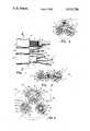
- FIG. 1is a fragmentary plan view of an electrical cable embodying the present invention.
- FIG. 2is a sectional view taken along the line 2--2 of FIG. 1.
- FIG. 3is similar to FIG. 2 but shows the components which comprise the cable in another position.
- FIG. 4is similar to FIG. 2 but shows another electrical cable embodying the present invention.
- an axially elongated, flexible electrical conductor assembly embodying the present invention and indicated generally by the reference numeral 10comprises a composite cable which includes components for providing power, CATV/DATA and telephone service.
- the illustrated cable 10is of a free-stripping type, particularly adapted to facilitate simultaneous installation of electrical conductors essential to the provision of such service and includes three components which comprise groups of electrical conductors designated generally by the numeral 12, 14 and 16.
- a unitary dielectric insulating jacket, indicated generally at 17,separates and insulates the electrical conductors which comprise each of the groups of conductors from the conductors of the other of the groups of conductors.
- the insulation jacket 17is preferably made from an elastomeric material, has three distinct free-stripping tubular portions each having a generally circular cross section.
- a first portion of the jacket, indicated by the numeral 18,generally coaxially surrounds the electrical conductors which comprise the first groups of conductors 12. These conductors are particularly adapted to supply telephone service.
- a second portion of the jacket, indicated by the numeral 20,generally coaxially surrounds the conductors of the second group 14, which constitute power supply conductors.
- a third portion of the jacket, indicated at 22,coaxially surrounds the third group 16, which comprises a coaxial cable arrangement for CATV/DATA service.
- the jacket second portion 20is connected to the first portion 18 along its length by an integral longitudinally extending web 24.
- a similar web 26connects the first portion 18 and the third portion 22.
- the webs 24 and 26are connected to the jacket first portion 18 at points of connection 27 and 29 angularly spaced about the central axis of the first tubular jacket portion 18 and located to one side of an axial plane 28 which contains the axis of the first portion 18.
- the webs 24 and 26provide flexible hinge connections as well as regions of weakening between the component parts of the cable 10, for purposes which will be hereinafter further evident.
- the conductor group 12which is particularly adapted to provide telephone service, preferably includes four non-twisted, individually insulated and color coded AWG No. 24 solid wire telecommunications conductors 32, 32.
- the power supply component which comprises the conductor group 14is particularly adapted for residential power supply and includes two insulated and color code AWG No. 14 solid wire conductors 34, 34 and an uninsulated or bare metallic ground conductor 36 contained within a generally cylindrical dielectric sheath defined by the jacket portion 20.
- the insulated conductors 34, 34 and the bare metallic conductor 36are surrounded by a spiral wrapping of metallic foil 38.
- the metallic foilwhich is preferably copper, comprises a flexible coaxial sleeve surrounding the conductors of the group 14, is contained within the dielectric insulation sheath 20 and is in immediate or interrupted electrical contacting engagement with the bare metallic conductor 36 along a substantial portion of its length for a purpose which will be hereinafter further evident.
- the CATV/DATA component 16conforms with present industry standards and includes a single AWG No. 20 solid wire conductor 40 coaxially surrounded by a generally cylindrical layer of foam dielectric material 42.
- a generally cylindrical flexible shield 44preferably formed by a spiral wrapping of aluminum foil, coaxially surrounds the dielectric layer 42.
- Another flexible cylindrical shield 46preferably made from sixty percent aluminum braided wire, coaxially surrounds the shield 44 within the insulation sheath formed by the generally cylindrical jacket portion 22.
- the web portions 24 and 26extend along the length of the cable 10 in generally parallel relation to the longitudinal axis of the cable and form flexible hinges between the components 12, 14 and 16 so that the three components may be positioned with the conductors thereof in generally side-by-side or in line relation, as shown in FIG. 2, to provide a substantially flat cable arrangement wherein the telephone component 12 is disposed generally between the power supply component 14 and the CATV/DATA component 16. In the latter position all of the conductors which comprise the cable 10 are disposed to the same side of a plane, indicated at 48, passing through the points of connection 27 and 29, as shown in FIG. 2.
- This side-by-side arrangement of the various conductorsfacilitates coiling or winding the cable 10 on a reel (not shown) which eliminates any substantial risk of kinking conductors.
- the arrangement of the hinged web connections between the various componentsis such that the cable 10 may be formed from the cross-sectional configuration shown in FIG. 2 to the cross-sectional configuration shown in FIG. 3 by hinged flexure of the components 14 and 16 at the webs 24 and 26 and relative to the component 12 and to each other, when the cable 10 is pulled from an associated reel.
- the cable componentsare arranged in a generally delta configuration, as shown in FIG.
- the components 20 and 22are disposed immediately adjacent each other and the conductors contained therein, which comprise the conductor of the second and third groups 14 and 16 are disposed to one side of the plane 48, whereas the conductors which comprise the first group 12 are disposed to the opposite side of the plane 48.
- the three components 12, 14 and 16lie within the boundary of an imaginary circle indicated by broken lines in FIG. 3. This arrangement of the components enables reduction of the major cross-sectional dimension of the cable so that it may pass freely through a circular opening of a predetermined size without encountering substantial frictional resistance.
- the illustrated cable 10is paticularly adapted for residential installation and is or may be sized to pass freely through a cylindrical hole of industry standard without substantial frictional resistance.
- the shield 38 in the power supply component 14also cooperates with the bare metallic ground conductor 38 to provide an important safety feature. If, during building construction, for example, a metal nail or staple is inadvertently driven through the power supply component and contacts a normally energized conductor, the nail or staple is at ground potential having passed through the metallic shield 38, which is grounded by the ground conductor or wire 36. Thus, the energized conductor will immediately short to ground. If this condition should occur during construction and before the cable is connected to a power source, the system will be shorted when the cable is connected to the power supply source. If the cable is properly handled this arrangement should prevent accidential energization of either the telephone component or the CATV/DATA component by the power supply component when the cable is installed.
- an additional metallic sleevemay be provided in the telephone service component 12 within the insulation sheath 18 and in generally coaxially surrounding relation to the conductors 32, 32 to further shield against both conducted and radiated noise interference.
- the connecting web portions 24 and 26comprise weakened regions of the insulation jacket 17 which enable the various free-stripping components 12, 14 and 16 to be readily selectively separated from each other.
- either and both of the components 14 and 16may be readily separated from the component 17 by applying tearing force to end parts of an appropriate two of the three components 12, 14 and 16.
- the tearing forceis, of course, applied in laterally opposite directions relative to the longitudinal axis of the conductor assembly 10.
- FIG. 4another electrical conductor assembly or cable embodying the present invention is indicated generally at 10a.
- the cable 10ais similar in many respects to the cable 10, previously described, and parts of the cable 10a which correspond to parts of the cable 10 are identified by the same reference numeral with a letter "a" suffix.
- the essential differences between the cable 10a and the previously described cable 10reside in the construction of the power supply component and its arrangement relative to the telephone and CATV/DATA components, which will be hereinafter described.
- the cable 10ahas a unitary dielectric insulation jacket indicated generally at 17a which includes distinct first, second and third jacket portions indicated respectively at 18a, 20a and 22a connected by webs 24a and 26a which provide flexible hinge connections between the various jacket portions, substantially as previously described.
- the illustrated cable 10ais a free-stripping type in that the various distinct tubular portions of the jacket 17a are not adhered to the components contained therein. Thus, when terminal ends of the tubular jacket portions are removed, the electrical conductors contained therein are exposed and are readily separable from each other and from the surrounding portion of the jacket.
- the first jacket portion 18acontains a power supply component which comprises a conductor group 14a and includes two insulated color coded solid wire conductors 34a, 34a and an uninsulated or bare metallic ground conductor 36a.
- An axially elongated shaped insulating spacer 50which preferably comprises a flexible elongated extrusion of dielectric plastic material, is also located within the jacket first portion 18a and serves to maintain the conductors 34a, 34a and 36a in generally predetermined spaced apart position relative to each other. As shown, the spacer 50 has axially extending arcuate grooves 52, 52 for receiving and retaining the conductors 34a, 34a and another arcuate groove 54 for receiving and containing the bare conductor 36a.
- a spiral wrapping of metallic foil 38ais located within the jacket portion 18a and surrounds the conductors which comprise the group 14a.
- the jacket portion 18apreferably closely surrounds the flexible metallic sleeve 38a, the conductors 34a, 34a and 36a and the spacer 50, substantially as shown in FIG. 4.
- the tubular jacket portion 18acooperates with the spacer 50 to retain the conductors which comprise the power supply component 14a in predetermined spaced relation to each other.
- the jacket portion 18acooperates with the spacer to maintain the bare metallic conductor 36a in substantial uninterrupted electrical contacting engagement with the flexible metallic shield 38a along a substantial portion of the length of the bare metallic conductor.
- the second jacket portion 20acontains a telephone component 12a which, as shown, includes eight individually insulated telecommunications conductors 32a, 32a.
- the illustrated jacket portion 20aalso contains a flexible metallic shield 56 formed by a wrapping of metallic foil and surrounding the conductors 32a, 32a. However, the shield 56 may be omitted, if desired.
- the third jacket portion 22acontains a CATV/DATA component 16a substantially identical to the component 16, previously described.
- the webs 24a and 26aare connected to the jacket portion 18a at points of connection indicated at 27a and 29a.
- the included angle between the points of connection 27a and 29a, as measured about the central axis of the jacket portion 18a and indicated by the letter A in FIG. 4,is preferably at least 60 degrees but not greater than 100 degrees.
- the length of each web as measured between its point of connection to the jacket portion 18a and its point of connection to an associated jacket portionis preferably as short as possible while allowing hinge flexure of the components between the full line and broken line portions of FIG. 4.
- the outer jacket 17apreferably comprises an extruded plastic material, being preferably extruded in the form in which it appears in full lines in FIG. 4, wherein the three service components are maintained in a Delta cross-sectional configuration relative to each other. In the latter position the three components lie within an imaginary circle, such as shown in broken lines in FIG. 4, which may, for example, represent a typical opening through which the cable 10a may be pulled.
- the second and third groups of electrical conductors 12a and 16aare disposed to one side of an imaginary plane 48a passing through the points of connection 27a and 29a.
- the conductors which comprise the first group 14aare disposed to the opposite of the plane 48a.
- all of the conductors which comprise the first, second and third groups of conductorsare generally disposed to the same side of the plane 48a and lie in generally side-by-side or in-line relation to each other so that the cable 10a may be would onto a reel (not shown) or the like with each of the conductors being wound to approximately the same radius as the others, whereby the risk of kinking the various conductors is minimized.
- the cable of the present inventionfacilitates cost-saving installation of power, video/computer and telephone service wiring.
- the telephone componentfacilitates the installation of many circuits for miscellaneous control, monitor or audio applications, as may be required.
Landscapes
- Details Of Indoor Wiring (AREA)
Abstract
Description
Claims (17)
Priority Applications (2)
| Application Number | Priority Date | Filing Date | Title |
|---|---|---|---|
| US06/589,169US4533790A (en) | 1983-02-16 | 1984-03-13 | Electrical conductor assembly |
| JP5021785AJPS612205A (en) | 1984-03-13 | 1985-03-13 | Electric conductor assembly |
Applications Claiming Priority (2)
| Application Number | Priority Date | Filing Date | Title |
|---|---|---|---|
| US46683383A | 1983-02-16 | 1983-02-16 | |
| US06/589,169US4533790A (en) | 1983-02-16 | 1984-03-13 | Electrical conductor assembly |
Related Parent Applications (1)
| Application Number | Title | Priority Date | Filing Date |
|---|---|---|---|
| US46683383AContinuation-In-Part | 1983-02-16 | 1983-02-16 |
Publications (1)
| Publication Number | Publication Date |
|---|---|
| US4533790Atrue US4533790A (en) | 1985-08-06 |
Family
ID=27041810
Family Applications (1)
| Application Number | Title | Priority Date | Filing Date |
|---|---|---|---|
| US06/589,169Expired - LifetimeUS4533790A (en) | 1983-02-16 | 1984-03-13 | Electrical conductor assembly |
Country Status (1)
| Country | Link |
|---|---|
| US (1) | US4533790A (en) |
Cited By (29)
| Publication number | Priority date | Publication date | Assignee | Title |
|---|---|---|---|---|
| US4697051A (en)* | 1985-07-31 | 1987-09-29 | At&T Technologies Inc., At&T Bell Laboratories | Data transmission system |
| US4755629A (en)* | 1985-09-27 | 1988-07-05 | At&T Technologies | Local area network cable |
| WO1990008388A1 (en)* | 1989-01-18 | 1990-07-26 | Amp Incorporated | Bundled hybrid ribbon electrical cable |
| US4952020A (en)* | 1989-08-09 | 1990-08-28 | Amp Incorporated | Ribbon cable with optical fibers and electrical conductors |
| US5068890A (en)* | 1986-10-22 | 1991-11-26 | Nilssen Ole K | Combined signal and electrical power distribution system |
| US5070522A (en)* | 1986-10-22 | 1991-12-03 | Nilssen Ole K | Combined signal and power distribution system |
| GB2244848A (en)* | 1990-05-03 | 1991-12-11 | Volex Group Plc | Composite cable and method of terminating cable |
| US5097099A (en)* | 1991-01-09 | 1992-03-17 | Amp Incorporated | Hybrid branch cable and shield |
| EP0476961A3 (en)* | 1990-09-17 | 1992-06-24 | Vantage Inc. | Cable assembly with lightning protection |
| US5162611A (en)* | 1990-03-21 | 1992-11-10 | Smarthouse, L. P. | Folded ribbon cable assembly having integral shielding |
| US5428187A (en)* | 1994-02-24 | 1995-06-27 | Molex Incorporated | Shielded hybrid ribbon cable assembly |
| US5719933A (en)* | 1994-02-18 | 1998-02-17 | Welch; Richard | Wiring arrangement for a communication interconnection system |
| EP0959547A1 (en)* | 1998-05-20 | 1999-11-24 | Soule Materiel Electrique | Multinetwork power supply utilizing a single cable |
| US6091025A (en)* | 1997-07-29 | 2000-07-18 | Khamsin Technologies, Llc | Electrically optimized hybird "last mile" telecommunications cable system |
| US6239379B1 (en) | 1998-07-29 | 2001-05-29 | Khamsin Technologies Llc | Electrically optimized hybrid “last mile” telecommunications cable system |
| WO2001050775A3 (en)* | 1999-12-29 | 2002-05-02 | Elisa Comm Oyj | Method for increasing data transfer capacity of a data communications network, such as a cable television network |
| EP1063656A3 (en)* | 1999-06-24 | 2002-07-31 | Corning Cable Systems LLC | Self- supporting cables and an apparatus and methods for making the same |
| US6684030B1 (en) | 1997-07-29 | 2004-01-27 | Khamsin Technologies, Llc | Super-ring architecture and method to support high bandwidth digital “last mile” telecommunications systems for unlimited video addressability in hub/star local loop architectures |
| KR100496452B1 (en)* | 2002-11-18 | 2005-06-20 | 엘에스전선 주식회사 | Hybrid cable for communication |
| US20050199416A1 (en)* | 2004-03-12 | 2005-09-15 | Somers Steve L. | Cable apparatus for minimizing skew delay of analog signals and cross-talk from digital signals and method of making same |
| WO2006026848A1 (en) | 2004-09-09 | 2006-03-16 | Soucy International Inc. | A snow and debris deflector for a track system |
| US20060160402A1 (en)* | 2004-12-29 | 2006-07-20 | Kowalski Wayne J | Power limited circuit cable for plenum applications in a constant current lighting system |
| US20120127648A1 (en)* | 2008-12-23 | 2012-05-24 | Nexsan Technologies Limited | Apparatus for Storing Data |
| US8976530B2 (en) | 2008-12-23 | 2015-03-10 | Nexsan Technologies Limited | Data storage apparatus |
| US20190097351A1 (en)* | 2017-09-23 | 2019-03-28 | Luxshare Precision Industry Co., Ltd. | Round cable |
| US10748677B1 (en)* | 2019-07-09 | 2020-08-18 | Chris Lee Nelson | Signal transmission cable configurable for variable electromagnetic field emission |
| US20200286647A1 (en)* | 2019-03-07 | 2020-09-10 | Hitachi Metals, Ltd. | Composite cable and composite harness |
| US20210241936A1 (en)* | 2020-02-04 | 2021-08-05 | Structured Home Wiring Direct, LLC | Composite Hybrid Cables and Methods of Manufacturing and Installing the Same |
| US20230223169A1 (en)* | 2020-09-24 | 2023-07-13 | Corning Research & Development Corporation | Cable with separable electrical conductors |
Citations (15)
| Publication number | Priority date | Publication date | Assignee | Title |
|---|---|---|---|---|
| US1940917A (en)* | 1930-08-04 | 1933-12-26 | Furukawa Denkikogyo Kabushiki | Multicore cable with cradle |
| US2403816A (en)* | 1944-06-16 | 1946-07-09 | Western Electric Co | Cord and method of making cord |
| US2501457A (en)* | 1945-07-20 | 1950-03-21 | Fenwal Inc | Fire detector cable |
| US2628998A (en)* | 1945-11-08 | 1953-02-17 | Gilbert Co A C | Splittable cable with visible conductors |
| US3023267A (en)* | 1959-03-05 | 1962-02-27 | Gen Cable Corp | Combination power and communication cable |
| US3328510A (en)* | 1965-03-22 | 1967-06-27 | Chillicothe Telephone Company | Combination telephone and co-axial conduit means |
| SE308747B (en)* | 1964-12-09 | 1969-02-24 | Asea Ab | |
| US3549788A (en)* | 1969-01-13 | 1970-12-22 | Bell Telephone Labor Inc | Flat-profile submarine coaxial cable with torque balance |
| DE2039870A1 (en)* | 1969-09-04 | 1971-04-29 | Allmaenna Svenska Elek Ska Ab | Electric cable |
| US3715458A (en)* | 1971-11-01 | 1973-02-06 | Belden Corp | Electrical cable structure |
| US3829603A (en)* | 1973-04-26 | 1974-08-13 | Anaconda Co | Power cable with grounding conductors |
| US3927247A (en)* | 1968-10-07 | 1975-12-16 | Belden Corp | Shielded coaxial cable |
| US4268714A (en)* | 1979-05-16 | 1981-05-19 | Sumitomo Electric Industries, Ltd. | Shielded wire |
| US4327246A (en)* | 1980-02-19 | 1982-04-27 | Belden Corporation | Electric cables with improved shielding members |
| US4383725A (en)* | 1979-06-14 | 1983-05-17 | Virginia Patent Development Corp. | Cable assembly having shielded conductor |
- 1984
- 1984-03-13USUS06/589,169patent/US4533790A/ennot_activeExpired - Lifetime
Patent Citations (15)
| Publication number | Priority date | Publication date | Assignee | Title |
|---|---|---|---|---|
| US1940917A (en)* | 1930-08-04 | 1933-12-26 | Furukawa Denkikogyo Kabushiki | Multicore cable with cradle |
| US2403816A (en)* | 1944-06-16 | 1946-07-09 | Western Electric Co | Cord and method of making cord |
| US2501457A (en)* | 1945-07-20 | 1950-03-21 | Fenwal Inc | Fire detector cable |
| US2628998A (en)* | 1945-11-08 | 1953-02-17 | Gilbert Co A C | Splittable cable with visible conductors |
| US3023267A (en)* | 1959-03-05 | 1962-02-27 | Gen Cable Corp | Combination power and communication cable |
| SE308747B (en)* | 1964-12-09 | 1969-02-24 | Asea Ab | |
| US3328510A (en)* | 1965-03-22 | 1967-06-27 | Chillicothe Telephone Company | Combination telephone and co-axial conduit means |
| US3927247A (en)* | 1968-10-07 | 1975-12-16 | Belden Corp | Shielded coaxial cable |
| US3549788A (en)* | 1969-01-13 | 1970-12-22 | Bell Telephone Labor Inc | Flat-profile submarine coaxial cable with torque balance |
| DE2039870A1 (en)* | 1969-09-04 | 1971-04-29 | Allmaenna Svenska Elek Ska Ab | Electric cable |
| US3715458A (en)* | 1971-11-01 | 1973-02-06 | Belden Corp | Electrical cable structure |
| US3829603A (en)* | 1973-04-26 | 1974-08-13 | Anaconda Co | Power cable with grounding conductors |
| US4268714A (en)* | 1979-05-16 | 1981-05-19 | Sumitomo Electric Industries, Ltd. | Shielded wire |
| US4383725A (en)* | 1979-06-14 | 1983-05-17 | Virginia Patent Development Corp. | Cable assembly having shielded conductor |
| US4327246A (en)* | 1980-02-19 | 1982-04-27 | Belden Corporation | Electric cables with improved shielding members |
Cited By (39)
| Publication number | Priority date | Publication date | Assignee | Title |
|---|---|---|---|---|
| US4697051A (en)* | 1985-07-31 | 1987-09-29 | At&T Technologies Inc., At&T Bell Laboratories | Data transmission system |
| US4755629A (en)* | 1985-09-27 | 1988-07-05 | At&T Technologies | Local area network cable |
| US5068890A (en)* | 1986-10-22 | 1991-11-26 | Nilssen Ole K | Combined signal and electrical power distribution system |
| US5070522A (en)* | 1986-10-22 | 1991-12-03 | Nilssen Ole K | Combined signal and power distribution system |
| WO1990008388A1 (en)* | 1989-01-18 | 1990-07-26 | Amp Incorporated | Bundled hybrid ribbon electrical cable |
| US5053583A (en)* | 1989-01-18 | 1991-10-01 | Amp Incorporated | Bundled hybrid ribbon electrical cable |
| US4952020A (en)* | 1989-08-09 | 1990-08-28 | Amp Incorporated | Ribbon cable with optical fibers and electrical conductors |
| US5162611A (en)* | 1990-03-21 | 1992-11-10 | Smarthouse, L. P. | Folded ribbon cable assembly having integral shielding |
| GB2244848A (en)* | 1990-05-03 | 1991-12-11 | Volex Group Plc | Composite cable and method of terminating cable |
| EP0476961A3 (en)* | 1990-09-17 | 1992-06-24 | Vantage Inc. | Cable assembly with lightning protection |
| US5097099A (en)* | 1991-01-09 | 1992-03-17 | Amp Incorporated | Hybrid branch cable and shield |
| US5719933A (en)* | 1994-02-18 | 1998-02-17 | Welch; Richard | Wiring arrangement for a communication interconnection system |
| US5428187A (en)* | 1994-02-24 | 1995-06-27 | Molex Incorporated | Shielded hybrid ribbon cable assembly |
| US6241920B1 (en) | 1997-07-29 | 2001-06-05 | Khamsin Technologies, Llc | Electrically optimized hybrid “last mile” telecommunications cable system |
| US6091025A (en)* | 1997-07-29 | 2000-07-18 | Khamsin Technologies, Llc | Electrically optimized hybird "last mile" telecommunications cable system |
| US6684030B1 (en) | 1997-07-29 | 2004-01-27 | Khamsin Technologies, Llc | Super-ring architecture and method to support high bandwidth digital “last mile” telecommunications systems for unlimited video addressability in hub/star local loop architectures |
| FR2779015A1 (en)* | 1998-05-20 | 1999-11-26 | Soule Materiel Electr | MULTI-NETWORK SUPPLY DEVICE USING A SINGLE CABLE |
| EP0959547A1 (en)* | 1998-05-20 | 1999-11-24 | Soule Materiel Electrique | Multinetwork power supply utilizing a single cable |
| US6847767B2 (en) | 1998-06-22 | 2005-01-25 | Corning Cable Systems Llc | Self-supporting cables and an apparatus and methods for making the same |
| US6563990B1 (en)* | 1998-06-22 | 2003-05-13 | Corning Cable Systems, Llc | Self-supporting cables and an apparatus and methods for making the same |
| US6239379B1 (en) | 1998-07-29 | 2001-05-29 | Khamsin Technologies Llc | Electrically optimized hybrid “last mile” telecommunications cable system |
| EP1063656A3 (en)* | 1999-06-24 | 2002-07-31 | Corning Cable Systems LLC | Self- supporting cables and an apparatus and methods for making the same |
| WO2001050775A3 (en)* | 1999-12-29 | 2002-05-02 | Elisa Comm Oyj | Method for increasing data transfer capacity of a data communications network, such as a cable television network |
| KR100496452B1 (en)* | 2002-11-18 | 2005-06-20 | 엘에스전선 주식회사 | Hybrid cable for communication |
| US20050199416A1 (en)* | 2004-03-12 | 2005-09-15 | Somers Steve L. | Cable apparatus for minimizing skew delay of analog signals and cross-talk from digital signals and method of making same |
| US7078626B2 (en)* | 2004-03-12 | 2006-07-18 | Rgb Systems, Inc. | Cable apparatus for minimizing skew delay of analog signals and cross-talk from digital signals and method of making same |
| WO2006026848A1 (en) | 2004-09-09 | 2006-03-16 | Soucy International Inc. | A snow and debris deflector for a track system |
| US20060160402A1 (en)* | 2004-12-29 | 2006-07-20 | Kowalski Wayne J | Power limited circuit cable for plenum applications in a constant current lighting system |
| US20120127648A1 (en)* | 2008-12-23 | 2012-05-24 | Nexsan Technologies Limited | Apparatus for Storing Data |
| US8976530B2 (en) | 2008-12-23 | 2015-03-10 | Nexsan Technologies Limited | Data storage apparatus |
| US9269401B2 (en)* | 2008-12-23 | 2016-02-23 | Nexsan Technologies Limited | Apparatus for storing data |
| US20190097351A1 (en)* | 2017-09-23 | 2019-03-28 | Luxshare Precision Industry Co., Ltd. | Round cable |
| US10424868B2 (en)* | 2017-09-23 | 2019-09-24 | Luxshare Precision Industry Co., Ltd. | Round cable |
| US20200286647A1 (en)* | 2019-03-07 | 2020-09-10 | Hitachi Metals, Ltd. | Composite cable and composite harness |
| US11569003B2 (en)* | 2019-03-07 | 2023-01-31 | Hitachi Metals, Ltd. | Composite cable and composite harness |
| US10748677B1 (en)* | 2019-07-09 | 2020-08-18 | Chris Lee Nelson | Signal transmission cable configurable for variable electromagnetic field emission |
| US20210241936A1 (en)* | 2020-02-04 | 2021-08-05 | Structured Home Wiring Direct, LLC | Composite Hybrid Cables and Methods of Manufacturing and Installing the Same |
| US11823817B2 (en)* | 2020-02-04 | 2023-11-21 | Structured Home Wiring Direct, LLC | Composite hybrid cables and methods of manufacturing and installing the same |
| US20230223169A1 (en)* | 2020-09-24 | 2023-07-13 | Corning Research & Development Corporation | Cable with separable electrical conductors |
Similar Documents
| Publication | Publication Date | Title |
|---|---|---|
| US4533790A (en) | Electrical conductor assembly | |
| US3023267A (en) | Combination power and communication cable | |
| US4956523A (en) | Armoured electric cable with integral tensile members | |
| US6486395B1 (en) | Interlocked metal-clad cable | |
| CA2334969A1 (en) | Pre-assembled electrical splice component | |
| EP0558463A1 (en) | An electric cable | |
| MX9801489A (en) | Local area network cabling arrangement. | |
| WO1992000592A1 (en) | An electrical cable | |
| US5397860A (en) | Multiple-core electrical ignition system cable | |
| US3193792A (en) | Connector-contact adapter | |
| US4232184A (en) | Cable adapter for converting a cable closure nozzle to a two cable entrance | |
| EP1502330B1 (en) | Rotating connection | |
| US5516302A (en) | End feed connector for pre-bussed rigid conduit | |
| US4192964A (en) | Modifiable stop element for cable connector assemblies | |
| US3800065A (en) | Grounded power cable | |
| US6281443B1 (en) | Electrical cable | |
| US5898350A (en) | Radiating coaxial cable and method for making the same | |
| US6664477B2 (en) | Insulator band, wiring system, and kit | |
| US6455777B1 (en) | Using bare stranded copper wire for grounding to conduit or steel channel | |
| US4447115A (en) | Multiple connection for an undersea cable system | |
| US2070141A (en) | Electric cable | |
| US5648640A (en) | Re-insulation of conductor junctions of primary conductors | |
| GB2294801A (en) | Fire and moisture resistant electric cable | |
| WO1999019213A3 (en) | Assembly for splicing multiple screened cables | |
| JPS612205A (en) | Electric conductor assembly |
Legal Events
| Date | Code | Title | Description |
|---|---|---|---|
| STCF | Information on status: patent grant | Free format text:PATENTED CASE | |
| FEPP | Fee payment procedure | Free format text:PAYOR NUMBER ASSIGNED (ORIGINAL EVENT CODE: ASPN); ENTITY STATUS OF PATENT OWNER: SMALL ENTITY | |
| FPAY | Fee payment | Year of fee payment:4 | |
| FEPP | Fee payment procedure | Free format text:PAYOR NUMBER ASSIGNED (ORIGINAL EVENT CODE: ASPN); ENTITY STATUS OF PATENT OWNER: SMALL ENTITY Free format text:PAT HOLDER CLAIMS SMALL ENTITY STATUS - SMALL BUSINESS (ORIGINAL EVENT CODE: SM02); ENTITY STATUS OF PATENT OWNER: SMALL ENTITY Free format text:PAYER NUMBER DE-ASSIGNED (ORIGINAL EVENT CODE: RMPN); ENTITY STATUS OF PATENT OWNER: SMALL ENTITY | |
| FPAY | Fee payment | Year of fee payment:8 | |
| SULP | Surcharge for late payment | ||
| AS | Assignment | Owner name:NORTHEAST PRODUCTS OF CONNECTICUT, INC., CONNECTIC Free format text:ASSIGNMENT OF ASSIGNORS INTEREST;ASSIGNOR:BICC CABLES CORPORATION;REEL/FRAME:008162/0259 Effective date:19910201 Owner name:INNOVATIVE CONNECTORS, LLC, NORTH CAROLINA Free format text:ASSIGNMENT OF ASSIGNORS INTEREST;ASSIGNOR:NORTHEAST PRODUCTS OF CONNECTICUT, INC.;REEL/FRAME:008162/0285 Effective date:19960715 Owner name:BRINTEC SYSTEMS CORPORATION, A DELAWARE CORPORATIO Free format text:CHANGE OF NAME;ASSIGNOR:BRAND-REX COMPANY;REEL/FRAME:008162/0295 Effective date:19850809 Owner name:BICC CABLES CORPORATION, A DELAWARE CORPORATION, N Free format text:MERGER AND NAME CHANGE;ASSIGNOR:BRINTEC SYSTEMS CORPORATION;REEL/FRAME:008162/0184 Effective date:19901226 | |
| FEPP | Fee payment procedure | Free format text:PAYOR NUMBER ASSIGNED (ORIGINAL EVENT CODE: ASPN); ENTITY STATUS OF PATENT OWNER: SMALL ENTITY Free format text:PAYER NUMBER DE-ASSIGNED (ORIGINAL EVENT CODE: RMPN); ENTITY STATUS OF PATENT OWNER: SMALL ENTITY | |
| REMI | Maintenance fee reminder mailed | ||
| FPAY | Fee payment | Year of fee payment:12 | |
| SULP | Surcharge for late payment |