US4531938A - Medicament implant applicator - Google Patents
Medicament implant applicatorDownload PDFInfo
- Publication number
- US4531938A US4531938AUS06/511,251US51125183AUS4531938AUS 4531938 AUS4531938 AUS 4531938AUS 51125183 AUS51125183 AUS 51125183AUS 4531938 AUS4531938 AUS 4531938A
- Authority
- US
- United States
- Prior art keywords
- chamber
- encasement
- drum
- medicament
- plunger
- Prior art date
- Legal status (The legal status is an assumption and is not a legal conclusion. Google has not performed a legal analysis and makes no representation as to the accuracy of the status listed.)
- Expired - Lifetime
Links
- 239000003814drugSubstances0.000titleclaimsabstractdescription47
- 239000007943implantSubstances0.000titleclaimsdescription47
- 239000007787solidSubstances0.000claimsabstractdescription13
- 230000000717retained effectEffects0.000claimsdescription3
- 239000008188pelletSubstances0.000abstractdescription25
- 241001465754MetazoaSpecies0.000abstractdescription17
- 238000003780insertionMethods0.000abstractdescription6
- 230000037431insertionEffects0.000abstractdescription6
- 210000003811fingerAnatomy0.000description8
- 239000004698PolyethyleneSubstances0.000description4
- -1polyethylenePolymers0.000description4
- 229920000573polyethylenePolymers0.000description4
- 241000283690Bos taurusSpecies0.000description3
- 238000002513implantationMethods0.000description3
- 238000000465mouldingMethods0.000description3
- 241000287828Gallus gallusSpecies0.000description1
- 238000013459approachMethods0.000description1
- 235000013330chicken meatNutrition0.000description1
- 238000006073displacement reactionMethods0.000description1
- 229940088597hormoneDrugs0.000description1
- 239000005556hormoneSubstances0.000description1
- 238000010137moulding (plastic)Methods0.000description1
- 210000000056organAnatomy0.000description1
- 238000004806packaging method and processMethods0.000description1
- 230000000284resting effectEffects0.000description1
- 230000004936stimulating effectEffects0.000description1
- 230000000638stimulationEffects0.000description1
- 210000003813thumbAnatomy0.000description1
Images


Classifications
- A—HUMAN NECESSITIES
- A61—MEDICAL OR VETERINARY SCIENCE; HYGIENE
- A61M—DEVICES FOR INTRODUCING MEDIA INTO, OR ONTO, THE BODY; DEVICES FOR TRANSDUCING BODY MEDIA OR FOR TAKING MEDIA FROM THE BODY; DEVICES FOR PRODUCING OR ENDING SLEEP OR STUPOR
- A61M37/00—Other apparatus for introducing media into the body; Percutany, i.e. introducing medicines into the body by diffusion through the skin
- A61M37/0069—Devices for implanting pellets, e.g. markers or solid medicaments
Definitions
- Solid or semi-solid pellets containing the growth stimulating hormonesare implanted in the neck or ear of the animal, to remain there for an extended period, even throughout the life span of the animal.
- the earis preferred implantation site, since the ear is a throwaway organ. Any implant residue present in the ear when the animal is slaughtered never enters channels of commerce, to become ingested by people or domestic animals.
- a typical medicament implanter devicecomprises a hand-held instrument built of a size consistent with the size of the animal (large for cattle, small for chickens.
- An apertured needle on the instrumentmakes a sizable, non-coring puncture opening into the skin e.g., of the ear of the animal and forms a cavity in the skin occupied temporarily by the needle on the instrument.
- the body of the instrumentmay be shaped like a hand gun, or alternatively, like a hypodermic syringe with a receiver-dispenser for the medicament implant.
- the needle of the implanteris inserted into the skin of the animal, then withdrawn. As the needle is being withdrawn from the animal, pellets of medicament are expelled into the cavity formed by the needle.
- an implant dosage unit formmay constitute a multiplicity, e.g., eight relatively small solid or semi-solid pellets.
- a reciprocal plunger inside the body of the implanterforces the pellet dosage unit out of a cartridge encasement wherein they were prepackaged into the bore of the needle and from there into the animal.
- a number of medicament implant deviceshave been suggested to the art, including devices adapted for use with cartridges or other encasement forms that contain a multiplicity of dosage units of the implants, U.S. Pat. No. 3,774,607, for example.
- This inventionrelates to the multi-dose aspect of the medicament implanter art.
- the principal object of the present inventionis to provide a novel implant applicator for implantation of the pellets.
- a further object of the inventionis to provide a novel multi-dosage indexable encasement adapted for use in the implant applicator of this invention.
- the applicator of this inventionincorporates certain features that are desirable in a multidose applicator, namely, orientation elements that force the user to load the applicator properly and which advise the user when reloading is required. Indeed, the structure of the applicator prevents its use after all the pellets have been discharged from the encasement. Features most desirable to the supplier of the medicament pellets are present.
- the multidose encasement of this inventionmay be filled somewhat more readily than single dose cartridges and can be packaged into a most compact form for shipment.
- the novel pellet implant encasement of this inventionresembles a cartridge belt in appearance.
- a multiplicitye.g., 20, of equally spaced apart chambers, are connected in a flexible web.
- Each chamberis sized to contain therein a dosage unit of medicament, suitably eight pellets.
- the encasementfits into the applicator and an animal handler can implant animals in succession, e.g., 20 animals, one after another, from each encasement.
- the implant applicator of this inventionlooks like a hypodermic syringe constructed with a large hub at the forward end of the syringe barrel.
- the medicament encasementis loaded inside of the hub.
- Ahead of the hubis the hollow needle; the plunger is, of course, to the rear of the syringe barrel.
- Forward movement of the plungerexpels the implant pellet(s) from one chamber of the encasement into and through the needle at the front end of the applicator. Then the plunger is pressed further forward as the needle is being withdrawn from an animal into which the needle had previously been inserted, thereby expelling the pellet(s) into the needle track.
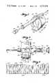
- FIG. 1is a diagrammatic view of the implant applicator.
- FIG. 2is a plan view of the implant applicator.
- FIG. 3is a front end view of the implant applicator.
- FIG. 4is a rear end view of the implant applicator.
- FIG. 5is a side view of the implant applicator, showing the applicator in opened position. The closed position is illustrated in shadow.
- FIG. 6is a partial side section taken along line 6--6 of FIG. 2 for an empty implant applicator.
- FIG. 7is a rear view similar to FIG. 4, with parts in section and the cover removed.
- FIG. 8is an enlarged partial section taken along line 8--8 of FIG. 6.
- FIG. 9is a plan view of an implant encasement.
- FIG. 10is a section taken along line 10--10 on FIG. 13.
- FIG. 11is a section taken along line 11--11 of FIG. 2 for a loaded implant applicator.
- FIG. 12is a partial section taken along line 12--12 of FIG. 2 for a loaded implant applicator.
- FIG. 13is a side view of an encasement loaded with the medicament pellets.
- the implant applicatorresembles a hypodermic syringe and also the many variations of such shape that have been suggested heretofore for implanting solid or semi-solid medicaments into domesticated animals.
- the applicatorcomprises front to rear, right to left on FIG. 1, but left to right on FIG. 2, a hollow needle 14 secured by a chuck 16 (or by any equivalent known to the art mounting structure) to the front of drum 18.
- Drum 18contains the medicament encasement therein.
- a tubular barrel 20 secured to the rear of drum 18is aligned to needle 14 so that the plunger 22 which is centered in barrel 20 is also centered for movement into needle 14.
- plunger 22can be advanced as far as the front end of needle 14.
- the barrel 20serves as a hand grip for holding the implant applicator when plunger 22 is advanced.
- Plunger 22terminates in a knob 24, the knob 24 serving as a grip for moving the plunger 22.
- the plunger length and travel distanceare predetermined so that when plunger 22 is fully extended to the rear, its forward end 23 will clear all moving parts inside of drum 18 (see FIG. 6).
- Standard known-to-the-art stop elementssuch as spring 25 inside barrel 20 and a shoulder 27 on plunger 22 prevent unintended forward movement by plunger 22.
- barrel 20terminates in a threaded boss 33 on the hub 30 containing a passageway 29 for plunger 22 (see FIG. 6).
- the wall of passageway 29serves to guide and center plunger 22.
- plunger 22may be formed from bar stock and knob 24 would then be a separate member threaded onto plunger 22.
- knob 32 mounted on the rear terminus of barrel 20can serve for finger grip purposes, including, if so desired, placement of wings thereon for better gripping. (See, for example, the structure suggested by U.S. Pat. No. 3,016,895).
- knob 32serves as a stop element, halting forward travel of plunger 22 when knobs 23 and 32 come together, which is just when the front end 23 of plunger 22 arrives at the forward edge of needle 14, and halting rearward travel of plunger 22 when shoulder 27 arrives at knob 32, which is just when front end 23 of plunger 22 retracts into hub 30.
- barrel 20is a section of tube stock that has been threaded at both ends, internally, for example.
- the knob 32threads in at the rear of the tube and the boss 33 of hub 30 threads in at the forward end of the tube (see FIG. 6).
- Hub 30suitably a plastic molding from polyethylene, for example, is an integral multipurpose member.
- hub 30On hub 30 is the externally threaded boss 33 to which the tube stock barrel 20 is attached.
- boss 33contains the passageway 29 for plunger 22.
- Hub 30is also part of drum 18, being principally the cover 31 that constitutes the generally circular rear face of drum 18.
- the implant applicator 10splits at the rear face of drum 18 with hub member 30 and barrel 20 pivotting on a hinge 40 away from the rest of drum 18 and needle 14.
- hinge half 33'At the top of hub 30 is hinge half 33'.
- a detent 35Formed at the bottom of the cover portion 31 of hub member 30 is a detent 35 that serves to latch the cover 31 to the balance of drum 18.
- an upstanding pin 37Formed on the forward face of hub 30 is an upstanding pin 37 (see FIGS. 5 and 6) which constitutes a stop element, as will be explained hereinafter.
- drum 18is formed from two cooperating members, the cover portion 31 of hub 30 discussed above and a drum base 34.
- the drum base 34is a multipurpose molded article from polyethylene, for example.
- drum base 34At the top of drum base 34 is a hinge-half 43' which mates with hinge-half 33', both halves being mounted on hinge pin 40.
- the drum base 34 and needle 14 of applicator 10can be pivoted on hinge pin 40 away from cover portion 31 and barrel 20 about 180°, as is illustrated in FIG. 5 to what can be called an open position.
- the inside of drum base 34is then exposed for loading a fresh medicament encasement therein, as will be explained hereinafter.
- the needle mounting structurecomprises known to the art features, which per se, form no part of this invention. Any of the many known equivalent needle mounting structures may be substituted for the arrangement herein illustrated.
- drum base 34is formed with the hinge-half 43' at the top thereof. At the bottom of drum base 34 is formed the seat for detent 35, including a detent aperture 55 into which detent 35 seats to latch hub 30 and drum base 34 to releasably permit opening and closing of the applicator.
- a tab 48 joined to the front of drum base 34extends front to rear of drum base 34 and beneath detent 35 around to the back of cover 31. By virtue of its length, tab 48 exhibits spring capability so that latch detent 35 can be seated in or released from 35 for closing or opening the applicator by pressing down on the thumb grip 53.
- drum base 34looks like an open drum for having a squat cylindrical wall portion 61, and a circular (front) face wall portion 63.
- Cover portion 31 of hub 30seats on cylindrical wall 61 to close off the inside of the drum base 34.
- the medicament encasement 100resembles a cartridge belt for comprising a series of equally spaced apart parallel cylindrical or conical chambers 102, twenty chambers, for example, connected into a flexible web by web sections 104.
- encasement 100is a unitary molded article, from polyethylene, for example.
- the chambers 102may be made ever so slightly conical as is herein illustrated (so that the molding equipment releases more readily). If chambers 102 are conical, the larger diameter ends should all be at the side of encasement 100 that will be entered by plunger 22. Conical encasement chambers 102 are normally filled from the larger diameter side.
- the medicament pellets 110are retained in each chamber 102 by internal tabs 106 molded in the chamber wall adjacent the narrow end of each chamber 102.
- the tabs 106reduce chamber clearance to less than diameter of the pellets which causes the pellets 110 to be retained inside chamber 102.
- Internal tabs 106may be formed on the inside chamber walls during the molding operation that makes the encasement 100.
- Upsets 108are made in each chamber wall at the wide diameter end of chambers 102 after insertion of the medicament pellets 110 inside chambers 102. Upsets 108 may be formed by the machinery that inserts the medicament pellets inside the chambers. Accordingly, the medicament pellets 110 cannot fall out either end of chamber 102 during later handling of the encasement 100. However, plunger 22 can push the relatively soft medicament pellets 110 past retaining tabs 106 to expel the implant pellet contents from chamber 102.
- encasement 100At one side end of encasement 100 is a dummy chamber 105 that is not intended to be filled with pellets.
- a slot 107is provided in the end side wall of dummy chamber 105.
- a solid cylindrical plug 115sized-to-fit inside of dummy chamber 105. Slot 107 is sized so plug 115 can be forced through slot 107 into dummy chamber 105. Presence of cylindrical plug 115 and dummy chamber 105 allows encasement 100 to be curved into the circlet mode that is required for use of encasement 100 in the applicator of this invention.
- medicament encasement 100contains a fail-safe feature that advises when all the medicament from a particular encasement has been utilized, that time has come to reload the implant applicator.
- an upstanding tab 109is provided at an end corner of encasement 100, suitably at the dummy chamber 105 end on the wider diameter or filling side of the chamber row, as may best be seen on FIGS. 10 and 13.
- Standard filling machineryis adapted to fill a multiplicity of cartridges simultaneously, from a twenty slot filling head for example.
- separate single dose cartridgeshave been used for implantation purposes, c.f. U.S. Pat. No. 2,761,446 and 3,744,493. This requires that a multiplicity of the separate cartridges must be placed into a filling fixture for the filling machine, which allows them to be filled as a single batch. The same operation can be done on essentially the same machinery with encasement 100 serving as package for the batch.
- the tab 109may be used to orient encasement 100 in a filling fixture for the machine so that all of the chambers 102 are filled from the filling side simultaneously. Dummy chamber 105 is, of course, not filled.
- a twenty-unit dosage encasementis somewhat easier to pass into and through conventional filling machinery than twenty separate cartridges.
- the multidose package of encasement 100 shown in FIG. 9is in flat form; a best form for packaging and shipment. Five or ten encasements can stack into a small oblong pack, which may be the package for shipment to an ultimate user. An appropriate number of such oblong packs can be boxed together for shipment to a wholesale distributor.
- a circlet formis desired.
- the usercurves encasement 100 into a circlet with plug 115 inserted into dummy chamber 105, e.g., forced through slot 107.
- Tab 109serves an orientation purpose.
- Encasement 100should be curved to place tab 109 at the inside of the circlet. If encasement 100 is curved so as to place tab 109 at the outside of the circlet, encasement 100 will not fit inside drum base 34 for reason that the effective diameter of the circlet will be too great.
- the circlet form encasement 100is sized to fit in drum base 35 adjacent cylindrical wall 61 provided tab 109 is at the open or rear face of drum base 34. If the user attempts to insert encasement 100 so that tab 109 will be adjacent the forward drum wall 63, tab would interfere with structure at the inside of drum base 34 and the encasement will not fit (see FIGS. 11 and 12) into drum base 34.
- a pair of arcuate guide portions 73 and 75are formed inside of drum base 34, near the top thereof (see FIGS. 6, 7, 8, and 11) are formed a pair of arcuate guide portions 73 and 75, one on each side of the center line 200 of drum base 34.
- Guides 73 and 75upstand from the inside face of circular wall 63. If such is desired, the accurate guides 73 and 75 may be extended at their bottom ends into nearly a full circle guide portion. As is shown on FIG. 6, the guides 73, 75 do not extend the full length of circular sidewall 61, leaving a gap adjacent cover 31 into which the pin 37 on cover 31 extends. Together with sidewall 61 guides 73 and 75 create an annular channel into which the medicament encasement 100 fits (see FIG.
- tab 109is positioned in the above mentioned free space adjacent cover 31, as is the stop element pin 37 on the inside of cover 31.
- Guide 75has a tab 75' at its end to indicate where to place tab 109. This is the start position for encasement 100. Tab 75' may also serve as a stop element.
- FIG. 11illustrates exactly where to position dummy chamber 105 and tab 109 when encasement 100 is loaded into implant applicator.
- a curved detent spring 79fills the gap between guides 73, 75 (see FIGS. 7, 8, 11).
- Spring ends 81, 83are mounted in channels provided for that purpose in posts 84 and 85 which respectively underlie and form part of guides 73, 75.
- the curved surface 87 on spring 79contains a recess 87 at the intersection of drum axis line 200 and the central axis for needle 14 and impeller 22 which recess provides a seat for a chamber 102 indexing that chamber with impeller 22, so that impeller 22 can pass through the indexed chamber to expel the chamber contents 110 into, then through needle 14.
- pin 37 on cover 31has been swung away from drum base 34.
- Pin 37can play no role in loading and unloading of the implant applicator.
- hub 30 and drum base 34are pivoted back and locked together in the use position of the implant applicator, pin 37 becomes located adjacent tab 109 between dummy chamber 105 and the chamber 102 adjacent thereto indexed on spring recess 87; see FIG. 12.
- Tab 75'is also in that locale; see FIG. 11, and if desired, together with or instead of pin 37 is employed for the stop function hereinafter described.
- Clockwise movement of encasement 100will shift each chamber 102 in succession onto the recess 87 of spring 79 until dummy chamber 105 approaches the indexed position, at which time tab 109 on medicament 100 is stopped by pin 37 (see FIG. 12).
- the encasement 100can no longer be rotated.
- the relative size and positions of tab 109 and pin 37will allow chamber 102 to move off recess 87, but prevent indexing thereon of dummy chamber 105. That chamber is filled by the non-expellable plug 115 in any event.
- the usercannot avoid recognizing when medicament encasement 100 has been emptied. Sheer inability to employ the applicator would advise the user that the applicator requires a fresh encasement.
- actuator 135is deposed, seated in grooves provided in wall portion 61 for that purpose.
- Actuator 135may be a unitary molded object, e.g., from polyethylene.
- a push-pull nose 133 on the actuatorextends through slot 130 to the outside of wall 61.
- the main body of actuator 135is an arcuate portion that rides inside the side wall 61 of drum base 34 and follows the general contour of wall 61.
- That portion of wall 61 adjacent main body 135is stepped outward to allow the actuator 135 to follow the wall contour as is illustrated in FIGS. 5 and 11.
- the main actuator 135terminates in pusher finger 94.
- Finger 94curves radially inward from main body 135, to a terminus point near the juncture of a web section 104 with a chamber 102. The curvature of and normal position of finger 94 provides clearance for proper insertion of encasement 100 into drum base 34.
- the length of travel allowed for actuator nose 133 in slot 130corresponds to the spacing between adjacent the chambers 102 of encasement 100.
- the first chamber 102is indexed in recess 87. Then, after discharge of the implant pellet medicament contents from the first chamber 102 followed by full retraction of plunger 22, which positions plunger end 23 clear of the chamber 102, as shown by FIG. 6, the user advances encasement 100 one chamber by pushing nose 133 from the base of slot 130 to the head thereof.
Landscapes
- Health & Medical Sciences (AREA)
- Engineering & Computer Science (AREA)
- Dermatology (AREA)
- Medical Informatics (AREA)
- Anesthesiology (AREA)
- Biomedical Technology (AREA)
- Heart & Thoracic Surgery (AREA)
- Hematology (AREA)
- Life Sciences & Earth Sciences (AREA)
- Animal Behavior & Ethology (AREA)
- General Health & Medical Sciences (AREA)
- Public Health (AREA)
- Veterinary Medicine (AREA)
- Infusion, Injection, And Reservoir Apparatuses (AREA)
Abstract
Description
Claims (6)
Priority Applications (2)
| Application Number | Priority Date | Filing Date | Title |
|---|---|---|---|
| US06/511,251US4531938A (en) | 1983-07-06 | 1983-07-06 | Medicament implant applicator |
| US06/597,376US4576591A (en) | 1983-07-06 | 1984-04-06 | Medicament implant applicator |
Applications Claiming Priority (1)
| Application Number | Priority Date | Filing Date | Title |
|---|---|---|---|
| US06/511,251US4531938A (en) | 1983-07-06 | 1983-07-06 | Medicament implant applicator |
Related Child Applications (1)
| Application Number | Title | Priority Date | Filing Date |
|---|---|---|---|
| US06/597,376Continuation-In-PartUS4576591A (en) | 1983-07-06 | 1984-04-06 | Medicament implant applicator |
Publications (1)
| Publication Number | Publication Date |
|---|---|
| US4531938Atrue US4531938A (en) | 1985-07-30 |
Family
ID=24034097
Family Applications (1)
| Application Number | Title | Priority Date | Filing Date |
|---|---|---|---|
| US06/511,251Expired - LifetimeUS4531938A (en) | 1983-07-06 | 1983-07-06 | Medicament implant applicator |
Country Status (1)
| Country | Link |
|---|---|
| US (1) | US4531938A (en) |
Cited By (32)
| Publication number | Priority date | Publication date | Assignee | Title |
|---|---|---|---|---|
| US4601699A (en)* | 1984-12-03 | 1986-07-22 | International Minerals & Chemical Corp. | Implant device |
| US4687465A (en)* | 1986-04-25 | 1987-08-18 | Ideal Instruments, Inc. | Automatic clip or pellet carrier fed pellet implanter apparatus |
| EP0308269A1 (en)* | 1987-09-18 | 1989-03-22 | Hoechst Veterinär GmbH | Cartridge for pellets |
| US4925030A (en)* | 1987-09-21 | 1990-05-15 | Schering Agrochemicals Limited | Cartridge |
| US4976686A (en)* | 1987-09-18 | 1990-12-11 | Schering Agrochemicals Limited | Implant gun |
| US4988335A (en)* | 1988-08-16 | 1991-01-29 | Ideal Instruments, Inc. | Pellet implanter apparatus |
| USD320270S (en) | 1987-09-21 | 1991-09-24 | Schering Agrochemicals Limited | Implant gun |
| US5106370A (en)* | 1991-01-23 | 1992-04-21 | Ideal Instruments, Inc. | Pellet carrier fed pellet implanter apparatus |
| US5135493A (en)* | 1990-09-10 | 1992-08-04 | Pitman-Moore, Inc. | Strip cartridge adapter and strip cartridge for implant device |
| AU646742B2 (en)* | 1991-06-24 | 1994-03-03 | Ideal Instruments, Inc. | Improved pellet carrier fed pellet implanter apparatus |
| US5665363A (en)* | 1994-02-18 | 1997-09-09 | Innovac Co. | Inoculation of animals with dried, pelleted biological materials |
| US6436068B1 (en)* | 2000-08-24 | 2002-08-20 | Gust H. Bardy | Instrument for implanting sensors and solid materials in a subcutaneous location and method thereof |
| US6488649B1 (en)* | 1998-11-24 | 2002-12-03 | Edward M. Lichten | Implant device |
| US20050067309A1 (en)* | 2003-09-25 | 2005-03-31 | Choi Jeung H. | Acupuncture needle container and dispenser |
| US20050067310A1 (en)* | 2003-09-25 | 2005-03-31 | Choi Jeung H. | Acupuncture needle container and dispenser |
| US20050115980A1 (en)* | 2003-10-30 | 2005-06-02 | Elmar Grandy | Container for holding sterile goods and sterile goods dispenser |
| US20070249992A1 (en)* | 2000-08-24 | 2007-10-25 | Bardy Gust H | Subcutaneous implantation instrument with dissecting tool and method of construction |
| US20100305582A1 (en)* | 2007-12-13 | 2010-12-02 | Microval | Apparatus for placing stitch turns resulting from a shape-memory metal thread |
| US20100324579A1 (en)* | 2000-08-24 | 2010-12-23 | Bardy Gust H | Instrument With A Covered Bore For Subcutaneous Implantation |
| US20100324578A1 (en)* | 2000-08-24 | 2010-12-23 | Bardy Gust H | Instrument With A Two-Part Plunger For Subcutaneous Implantation |
| US20100331868A1 (en)* | 2000-08-24 | 2010-12-30 | Bardy Gust H | Method For Constructing An Instrument With A Two-Part Plunger For Subcutaneous Implantation |
| US20100331874A1 (en)* | 2000-08-24 | 2010-12-30 | Bardy Gust H | Method for constructing an instrument with a covered bore for subcutaneous implantation |
| US20130273173A1 (en)* | 2010-03-22 | 2013-10-17 | Incube Labs, Llc | Solid drug delivery apparatus, formulations and methods of use |
| US20140090997A1 (en)* | 2011-05-11 | 2014-04-03 | Sanofi-Aventis Deutschland Gmbh | Needle assembly storage device |
| US8932268B1 (en)* | 2013-09-23 | 2015-01-13 | Edward D. Struzinski | Medication cartridge injection assembly |
| US9545282B2 (en) | 2013-03-09 | 2017-01-17 | Ebi, Llc | Bone graft delivery apparatus |
| US10869770B2 (en) | 2017-12-11 | 2020-12-22 | Stryker European Holdings I, Llc | Bone graft delivery revolver |
| US11413442B2 (en) | 2016-06-23 | 2022-08-16 | Warsaw Orthopedic, Inc. | Drug delivery device and methods having a retaining member |
| US11464958B2 (en) | 2014-07-25 | 2022-10-11 | Warsaw Orthopedic, Inc. | Drug delivery methods having an occluding member |
| US11478587B2 (en) | 2016-11-08 | 2022-10-25 | Warsaw Orthopedic, Inc. | Drug depot delivery system and method |
| US11504513B2 (en) | 2014-07-25 | 2022-11-22 | Warsaw Orthopedic, Inc. | Drug delivery device and methods having a retaining member |
| US11759614B2 (en) | 2015-11-23 | 2023-09-19 | Warsaw Orthopedic, Inc. | Enhanced stylet for drug depot injector |
Citations (3)
| Publication number | Priority date | Publication date | Assignee | Title |
|---|---|---|---|---|
| US3774607A (en)* | 1971-11-22 | 1973-11-27 | Commercial Solvents Corp | Pellet implant gun |
| US4077406A (en)* | 1976-06-24 | 1978-03-07 | American Cyanamid Company | Pellet implanter for animal treatment |
| US4400170A (en)* | 1981-09-29 | 1983-08-23 | Syntex (U.S.A.) Inc. | Implanting device and implant magazine |
- 1983
- 1983-07-06USUS06/511,251patent/US4531938A/ennot_activeExpired - Lifetime
Patent Citations (3)
| Publication number | Priority date | Publication date | Assignee | Title |
|---|---|---|---|---|
| US3774607A (en)* | 1971-11-22 | 1973-11-27 | Commercial Solvents Corp | Pellet implant gun |
| US4077406A (en)* | 1976-06-24 | 1978-03-07 | American Cyanamid Company | Pellet implanter for animal treatment |
| US4400170A (en)* | 1981-09-29 | 1983-08-23 | Syntex (U.S.A.) Inc. | Implanting device and implant magazine |
Cited By (57)
| Publication number | Priority date | Publication date | Assignee | Title |
|---|---|---|---|---|
| US4601699A (en)* | 1984-12-03 | 1986-07-22 | International Minerals & Chemical Corp. | Implant device |
| US4687465A (en)* | 1986-04-25 | 1987-08-18 | Ideal Instruments, Inc. | Automatic clip or pellet carrier fed pellet implanter apparatus |
| US4976686A (en)* | 1987-09-18 | 1990-12-11 | Schering Agrochemicals Limited | Implant gun |
| EP0308269A1 (en)* | 1987-09-18 | 1989-03-22 | Hoechst Veterinär GmbH | Cartridge for pellets |
| USD320270S (en) | 1987-09-21 | 1991-09-24 | Schering Agrochemicals Limited | Implant gun |
| AU616905B2 (en)* | 1987-09-21 | 1991-11-14 | Sanofi Sante Nutrition Animale Sa | Cartridge |
| US4925030A (en)* | 1987-09-21 | 1990-05-15 | Schering Agrochemicals Limited | Cartridge |
| US4988335A (en)* | 1988-08-16 | 1991-01-29 | Ideal Instruments, Inc. | Pellet implanter apparatus |
| US5135493A (en)* | 1990-09-10 | 1992-08-04 | Pitman-Moore, Inc. | Strip cartridge adapter and strip cartridge for implant device |
| US5106370A (en)* | 1991-01-23 | 1992-04-21 | Ideal Instruments, Inc. | Pellet carrier fed pellet implanter apparatus |
| AU646742B2 (en)* | 1991-06-24 | 1994-03-03 | Ideal Instruments, Inc. | Improved pellet carrier fed pellet implanter apparatus |
| US5665363A (en)* | 1994-02-18 | 1997-09-09 | Innovac Co. | Inoculation of animals with dried, pelleted biological materials |
| US6488649B1 (en)* | 1998-11-24 | 2002-12-03 | Edward M. Lichten | Implant device |
| US8435208B2 (en) | 2000-08-24 | 2013-05-07 | Cardiac Science Corporation | Subcutaneous implantation instrument with a scissored dissecting tool assembly and method of construction |
| US8251946B2 (en) | 2000-08-24 | 2012-08-28 | Cardiac Science, Inc. | Method for constructing an instrument with a two-part plunger for subcutaneous implantation |
| US8454552B2 (en) | 2000-08-24 | 2013-06-04 | Cardiac Science Corporation | Method for constructing an instrument with a covered bore for subcutaneous implantation |
| US20100331868A1 (en)* | 2000-08-24 | 2010-12-30 | Bardy Gust H | Method For Constructing An Instrument With A Two-Part Plunger For Subcutaneous Implantation |
| US20050165347A1 (en)* | 2000-08-24 | 2005-07-28 | Bardy Gust H. | Instrument for implanting sensors and solid materials in a subcutaneous location and method thereof |
| US8394050B2 (en) | 2000-08-24 | 2013-03-12 | Cardiac Science Corporation | Straight cutting tip for a straight bore subcutaneous implantation instrument |
| US8348882B2 (en) | 2000-08-24 | 2013-01-08 | Cardiac Science Corporation | Instrument with a covered bore for subcutaneous implantation |
| US8323232B2 (en) | 2000-08-24 | 2012-12-04 | Cardiac Science Corporation | Instrument with a two-part plunger for subcutaneous implantation |
| US20070249992A1 (en)* | 2000-08-24 | 2007-10-25 | Bardy Gust H | Subcutaneous implantation instrument with dissecting tool and method of construction |
| US6436068B1 (en)* | 2000-08-24 | 2002-08-20 | Gust H. Bardy | Instrument for implanting sensors and solid materials in a subcutaneous location and method thereof |
| US7736330B2 (en) | 2000-08-24 | 2010-06-15 | Bardy Gust H | Subcutaneous implantation instrument with dissecting tool and method of construction |
| US7780625B2 (en) | 2000-08-24 | 2010-08-24 | Bardy Gust H | Instrument for implanting sensors and solid materials in a subcutaneous location and method thereof |
| US20100217298A1 (en)* | 2000-08-24 | 2010-08-26 | Bardy Gust H | Subcutaneous Implantation Instrument With A Scissored Dissecting Tool Assembly And Method Of Construction |
| US20100217301A1 (en)* | 2000-08-24 | 2010-08-26 | Bardy Gust H | Method For Implanting A Non-Liquid Object |
| US20100249696A1 (en)* | 2000-08-24 | 2010-09-30 | Bardy Gust H | Straight cutting tip for a full large bore subcutaneous implantation instrument |
| US20100331874A1 (en)* | 2000-08-24 | 2010-12-30 | Bardy Gust H | Method for constructing an instrument with a covered bore for subcutaneous implantation |
| US20100318022A1 (en)* | 2000-08-24 | 2010-12-16 | Bardy Gust H | Straight Cutting Tip For A Straight Bore Subcutaneous Implantation Instrument |
| US20100324579A1 (en)* | 2000-08-24 | 2010-12-23 | Bardy Gust H | Instrument With A Covered Bore For Subcutaneous Implantation |
| US20100324578A1 (en)* | 2000-08-24 | 2010-12-23 | Bardy Gust H | Instrument With A Two-Part Plunger For Subcutaneous Implantation |
| US20050067309A1 (en)* | 2003-09-25 | 2005-03-31 | Choi Jeung H. | Acupuncture needle container and dispenser |
| US7240806B2 (en) | 2003-09-25 | 2007-07-10 | Choi Jeung H | Acupuncture needle container and dispenser |
| WO2005030110A3 (en)* | 2003-09-25 | 2007-03-15 | Jeung H Choi | Acupuncture needle container and dispenser |
| US7004352B2 (en) | 2003-09-25 | 2006-02-28 | Choi Jeung H | Acupuncture needle container and dispenser |
| US20050067310A1 (en)* | 2003-09-25 | 2005-03-31 | Choi Jeung H. | Acupuncture needle container and dispenser |
| US7347342B2 (en)* | 2003-10-30 | 2008-03-25 | Elmar Grandy | Container for holding sterile goods and sterile goods dispenser |
| US20050115980A1 (en)* | 2003-10-30 | 2005-06-02 | Elmar Grandy | Container for holding sterile goods and sterile goods dispenser |
| US20100305582A1 (en)* | 2007-12-13 | 2010-12-02 | Microval | Apparatus for placing stitch turns resulting from a shape-memory metal thread |
| US8403944B2 (en)* | 2007-12-13 | 2013-03-26 | Microval | Apparatus for placing stitch turns resulting from a shape-memory metal thread |
| US20150265634A1 (en)* | 2010-03-22 | 2015-09-24 | Incube Labs, Llc | Solid drug delivery apparatus, formulations and methods of use |
| US20130273173A1 (en)* | 2010-03-22 | 2013-10-17 | Incube Labs, Llc | Solid drug delivery apparatus, formulations and methods of use |
| US9974797B2 (en)* | 2010-03-22 | 2018-05-22 | Incube Labs, Llc | Solid drug delivery apparatus, formulations and methods of use |
| US9072877B2 (en)* | 2010-03-22 | 2015-07-07 | Incube Labs, Llc | Solid drug delivery apparatus, formulations and methods of use |
| US20140090997A1 (en)* | 2011-05-11 | 2014-04-03 | Sanofi-Aventis Deutschland Gmbh | Needle assembly storage device |
| US9545282B2 (en) | 2013-03-09 | 2017-01-17 | Ebi, Llc | Bone graft delivery apparatus |
| US8932268B1 (en)* | 2013-09-23 | 2015-01-13 | Edward D. Struzinski | Medication cartridge injection assembly |
| US11464958B2 (en) | 2014-07-25 | 2022-10-11 | Warsaw Orthopedic, Inc. | Drug delivery methods having an occluding member |
| US11504513B2 (en) | 2014-07-25 | 2022-11-22 | Warsaw Orthopedic, Inc. | Drug delivery device and methods having a retaining member |
| US11759614B2 (en) | 2015-11-23 | 2023-09-19 | Warsaw Orthopedic, Inc. | Enhanced stylet for drug depot injector |
| US11413442B2 (en) | 2016-06-23 | 2022-08-16 | Warsaw Orthopedic, Inc. | Drug delivery device and methods having a retaining member |
| US12076519B2 (en) | 2016-06-23 | 2024-09-03 | Warsaw Orthopedic, Inc. | Drug delivery device and methods having a retaining member |
| US12017050B2 (en) | 2016-11-08 | 2024-06-25 | Warsaw Orthopedic, Inc. | Drug depot delivery system and method |
| US11478587B2 (en) | 2016-11-08 | 2022-10-25 | Warsaw Orthopedic, Inc. | Drug depot delivery system and method |
| US10869770B2 (en) | 2017-12-11 | 2020-12-22 | Stryker European Holdings I, Llc | Bone graft delivery revolver |
| US11471302B2 (en) | 2017-12-11 | 2022-10-18 | Stryker European Operations Holdings Llc | Bone graft delivery revolver |
Similar Documents
| Publication | Publication Date | Title |
|---|---|---|
| US4531938A (en) | Medicament implant applicator | |
| US4576591A (en) | Medicament implant applicator | |
| US4223674A (en) | Implant gun | |
| US4451254A (en) | Implant system | |
| US4936827A (en) | Implanter applicator | |
| US20210268249A1 (en) | Kit for and method of assembling an applicator for inserting an implant | |
| US4154239A (en) | Drug pellet implanter | |
| FI110577B (en) | An implant | |
| US6949064B2 (en) | Brachytherapy seed deployment system | |
| US6837844B1 (en) | Seed cartridge for radiation therapy | |
| EP0077145B1 (en) | Implanting device | |
| US4077406A (en) | Pellet implanter for animal treatment | |
| US4820267A (en) | Cartridge injector for pellet medicaments | |
| JP2731756B2 (en) | Needle dispenser for medication pens | |
| CS133492A3 (en) | Portable system for medicaments administration | |
| KR100844031B1 (en) | Adjustable Dosing Syringe | |
| HU220126B (en) | Medical device for inserting solid materials either under a tissue or under the skin | |
| AU2001294661A1 (en) | Adjustable dosage syringe | |
| US7004352B2 (en) | Acupuncture needle container and dispenser | |
| US4946035A (en) | Implanter applicator | |
| US5129914A (en) | Acupuncture needle container and insertion tube | |
| US7588528B2 (en) | Brachytherapy apparatus for dispensing medication | |
| US4601699A (en) | Implant device | |
| WO2019133390A1 (en) | Pen needle assembly apparatus | |
| US20230149635A1 (en) | Applicator for Implant Insertion |
Legal Events
| Date | Code | Title | Description |
|---|---|---|---|
| AS | Assignment | Owner name:IVY-GENE COMPANY, INC., WASHINGTON, D.C, A DE COR Free format text:ASSIGNMENT OF ASSIGNORS INTEREST.;ASSIGNORS:KAYE, GORDON E.;SCHWARTZ, EUGENE B.;SOLLINS, IRVING V.;REEL/FRAME:004377/0618;SIGNING DATES FROM 19850305 TO 19850311 | |
| AS | Assignment | Owner name:IVY LABORATORIES, INC. Free format text:CHANGE OF NAME;ASSIGNOR:IVY-GENE COMPANY, INC.;REEL/FRAME:005038/0018 Effective date:19850724 | |
| FEPP | Fee payment procedure | Free format text:PETITION RELATED TO MAINTENANCE FEES FILED (ORIGINAL EVENT CODE: PMFP); ENTITY STATUS OF PATENT OWNER: SMALL ENTITY | |
| REMI | Maintenance fee reminder mailed | ||
| REIN | Reinstatement after maintenance fee payment confirmed | ||
| FP | Lapsed due to failure to pay maintenance fee | Effective date:19890730 | |
| FEPP | Fee payment procedure | Free format text:PETITION RELATED TO MAINTENANCE FEES DENIED/DISMISSED (ORIGINAL EVENT CODE: PMFD); ENTITY STATUS OF PATENT OWNER: SMALL ENTITY | |
| FEPP | Fee payment procedure | Free format text:PETITION RELATED TO MAINTENANCE FEES FILED (ORIGINAL EVENT CODE: PMFP); ENTITY STATUS OF PATENT OWNER: SMALL ENTITY | |
| FEPP | Fee payment procedure | Free format text:PETITION RELATED TO MAINTENANCE FEES GRANTED (ORIGINAL EVENT CODE: PMFG); ENTITY STATUS OF PATENT OWNER: SMALL ENTITY | |
| FPAY | Fee payment | Year of fee payment:4 | |
| SULP | Surcharge for late payment | ||
| STCF | Information on status: patent grant | Free format text:PATENTED CASE | |
| DP | Notification of acceptance of delayed payment of maintenance fee | ||
| FEPP | Fee payment procedure | Free format text:PAYOR NUMBER ASSIGNED (ORIGINAL EVENT CODE: ASPN); ENTITY STATUS OF PATENT OWNER: SMALL ENTITY | |
| FPAY | Fee payment | Year of fee payment:8 | |
| FEPP | Fee payment procedure | Free format text:PAYER NUMBER DE-ASSIGNED (ORIGINAL EVENT CODE: RMPN); ENTITY STATUS OF PATENT OWNER: SMALL ENTITY | |
| FPAY | Fee payment | Year of fee payment:12 | |
| AS | Assignment | Owner name:IVY ANIMAL HEALTH, INC., KANSAS Free format text:MERGER AND CHANGE OF NAME;ASSIGNOR:IVY LABORATORIES, INC.;REEL/FRAME:010238/0766 Effective date:19981229 |