US4531524A - Circuit apparatus and method for electrothermal treatment of cancer eye - Google Patents
Circuit apparatus and method for electrothermal treatment of cancer eyeDownload PDFInfo
- Publication number
- US4531524A US4531524AUS06/453,811US45381182AUS4531524AUS 4531524 AUS4531524 AUS 4531524AUS 45381182 AUS45381182 AUS 45381182AUS 4531524 AUS4531524 AUS 4531524A
- Authority
- US
- United States
- Prior art keywords
- tissue
- temperature
- duty cycle
- signal
- circuit means
- Prior art date
- Legal status (The legal status is an assumption and is not a legal conclusion. Google has not performed a legal analysis and makes no representation as to the accuracy of the status listed.)
- Expired - Lifetime
Links
- 238000011282treatmentMethods0.000titleclaimsabstractdescription27
- 238000000034methodMethods0.000titleclaimsdescription23
- 206010028980NeoplasmDiseases0.000titledescription30
- 201000011510cancerDiseases0.000titledescription25
- 239000000523sampleSubstances0.000claimsabstractdescription80
- 238000010438heat treatmentMethods0.000claimsabstractdescription12
- 230000001105regulatory effectEffects0.000claimsdescription14
- 238000004804windingMethods0.000claimsdescription9
- 230000010355oscillationEffects0.000claimsdescription5
- 230000000630rising effectEffects0.000claimsdescription5
- 230000005669field effectEffects0.000claimsdescription4
- 238000013021overheatingMethods0.000claimsdescription4
- 230000004044responseEffects0.000claimsdescription4
- 230000009467reductionEffects0.000claimsdescription2
- 238000012935AveragingMethods0.000claims1
- 230000003211malignant effectEffects0.000abstractdescription13
- 244000144972livestockSpecies0.000abstractdescription4
- 230000000737periodic effectEffects0.000abstractdescription2
- 230000002829reductive effectEffects0.000abstractdescription2
- 239000004020conductorSubstances0.000description99
- 210000001508eyeAnatomy0.000description29
- 239000003990capacitorSubstances0.000description13
- 241001465754MetazoaSpecies0.000description9
- 241000283690Bos taurusSpecies0.000description6
- 239000002699waste materialSubstances0.000description4
- 210000005252bulbus oculiAnatomy0.000description3
- 238000010586diagramMethods0.000description3
- 239000000919ceramicSubstances0.000description2
- 230000000694effectsEffects0.000description2
- 208000024519eye neoplasmDiseases0.000description2
- 201000008106ocular cancerDiseases0.000description2
- 238000011160researchMethods0.000description2
- 238000013459approachMethods0.000description1
- 230000008901benefitEffects0.000description1
- 230000000740bleeding effectEffects0.000description1
- 230000003247decreasing effectEffects0.000description1
- 210000000744eyelidAnatomy0.000description1
- 230000003100immobilizing effectEffects0.000description1
- 238000012986modificationMethods0.000description1
- 230000004048modificationEffects0.000description1
- 230000005855radiationEffects0.000description1
- 230000000452restraining effectEffects0.000description1
- 230000002441reversible effectEffects0.000description1
- 238000012552reviewMethods0.000description1
- 229920006395saturated elastomerPolymers0.000description1
- 230000008470skin growthEffects0.000description1
- 238000003307slaughterMethods0.000description1
- 230000002459sustained effectEffects0.000description1
Images
Classifications
- A—HUMAN NECESSITIES
- A61—MEDICAL OR VETERINARY SCIENCE; HYGIENE
- A61B—DIAGNOSIS; SURGERY; IDENTIFICATION
- A61B18/00—Surgical instruments, devices or methods for transferring non-mechanical forms of energy to or from the body
- A61B18/04—Surgical instruments, devices or methods for transferring non-mechanical forms of energy to or from the body by heating
- A61B18/12—Surgical instruments, devices or methods for transferring non-mechanical forms of energy to or from the body by heating by passing a current through the tissue to be heated, e.g. high-frequency current
- A61B18/1206—Generators therefor
- A—HUMAN NECESSITIES
- A61—MEDICAL OR VETERINARY SCIENCE; HYGIENE
- A61B—DIAGNOSIS; SURGERY; IDENTIFICATION
- A61B18/00—Surgical instruments, devices or methods for transferring non-mechanical forms of energy to or from the body
- A61B18/04—Surgical instruments, devices or methods for transferring non-mechanical forms of energy to or from the body by heating
- A61B18/12—Surgical instruments, devices or methods for transferring non-mechanical forms of energy to or from the body by heating by passing a current through the tissue to be heated, e.g. high-frequency current
- A61B18/14—Probes or electrodes therefor
- A61B18/1402—Probes for open surgery
- A—HUMAN NECESSITIES
- A61—MEDICAL OR VETERINARY SCIENCE; HYGIENE
- A61D—VETERINARY INSTRUMENTS, IMPLEMENTS, TOOLS, OR METHODS
- A61D1/00—Surgical instruments for veterinary use
- A—HUMAN NECESSITIES
- A61—MEDICAL OR VETERINARY SCIENCE; HYGIENE
- A61B—DIAGNOSIS; SURGERY; IDENTIFICATION
- A61B17/00—Surgical instruments, devices or methods
- A61B2017/00017—Electrical control of surgical instruments
- A61B2017/00022—Sensing or detecting at the treatment site
- A61B2017/00084—Temperature
- A61B2017/00088—Temperature using thermistors
- A—HUMAN NECESSITIES
- A61—MEDICAL OR VETERINARY SCIENCE; HYGIENE
- A61B—DIAGNOSIS; SURGERY; IDENTIFICATION
- A61B17/00—Surgical instruments, devices or methods
- A61B2017/00017—Electrical control of surgical instruments
- A61B2017/00115—Electrical control of surgical instruments with audible or visual output
- A—HUMAN NECESSITIES
- A61—MEDICAL OR VETERINARY SCIENCE; HYGIENE
- A61B—DIAGNOSIS; SURGERY; IDENTIFICATION
- A61B17/00—Surgical instruments, devices or methods
- A61B2017/00017—Electrical control of surgical instruments
- A61B2017/00132—Setting operation time of a device
- A—HUMAN NECESSITIES
- A61—MEDICAL OR VETERINARY SCIENCE; HYGIENE
- A61B—DIAGNOSIS; SURGERY; IDENTIFICATION
- A61B18/00—Surgical instruments, devices or methods for transferring non-mechanical forms of energy to or from the body
- A61B2018/00636—Sensing and controlling the application of energy
- A61B2018/0066—Sensing and controlling the application of energy without feedback, i.e. open loop control
Definitions
- the inventionrelates to apparatus and methods for treating malignant tissue known as "cancer eye" in the eyes of livestock by applying high frequency current, by means of spaced probes, to the malignant tissue to increase the temperature thereof to a level which is high enough to kill the malignant tissue but is low enough to avoid permanent damage to the adjacent healthy tissue.
- cancer eyeBenign and malignant tumors of the eye and eyelid in cattle are generally referred to by the term "cancer eye". Approximately 80% of such tumors are malignant and many of the rest become malignant with time. Cancer eye is a serious problem throughout the United States, especially in high elevation locations where solar radiation is most intense. As pointed out by his article "Electrothermal treatment of Cancer Eye” by James D. Doss, published in the August 1977 issue of the LASL Mini-Review, 77-14, published in 1975 by the Los Alamos Scientific Laboratory of the University of California at Los Alamos, N. Mex., cancer eye was the leading individual cause of cattle carcass condemnation at slaughter houses inspected by the U.S. Department of Agriculture.
- the instrumentemits periodic audible beeps every second, allowing the user to measure the amount of time adequate pressure of the electrodes is maintained against the surface of the tumor (for 30 seconds) by counting thirty beeps.
- a device manufactured by Veterinary Products Industries, of Phoenix, Ariz., referred to as the THERM.I.CURER LCF (localized current field) electronic probehas been developed based on the above-mentioned research. This device produces an initial heat surge to a temperature of about 160° F. (60° C.) to 180° F. (68° C.) and then drops back to the sustained temperature of 50° C. for the required 30 second treatment. This initial surge is supposed to have a cauterizing effect that stops any bleeding, but, in fact, can cause undue permanent damage to healthy eye tissue.
- the previous electrothermal devices and treatmentswhile representing a breakthrough in the treatment of cancer eye in cattle, nevertheless present certain unsolved problems.
- the animal being treatedusually vigorously resists attempts to restrain it, causing difficulty to the veterinary in maintaining adequate contact of the current probe contact surfaces with the tumorous tissue.
- the temperature of the tissuemay not reach or maintain the necessary temperature of 50° C.
- One of the previous electrothermal devicesdissipates far too much power in the circuitry located in the handle of the device. Since it is frequently desirable to use the device at locations where electrical power is not available, it is highly desirable that the electrothermal devices be lightweight and battery-powered.
- the inventionprovides a method and apparatus for accomplishing electrothermal treatment of malignant or tumorous tissue by providing an audible sound, the pitch of which represents the temperature of a high frequency current conducted by a pair of spaced probes which are held against the malignant or tumorous tissue. If the pressure of the contact surface of the high frequency current probes against the tissue is maintained at an adequate level, electrical contact also will be maintained, and the temperature of the tissue, and hence, of the probes steadily increases to a predetermined temperature due to a high frequency current flowing from one probe through the tissue and into the other probe. The probes are heated by thermal conduction of heat from the tissue to the probes.
- the steadily increasing pitch of the audible soundinforms the user of the apparatus that sufficient pressure is being applied by the probe contact surfaces to the malignant tissue to provide the necessary degree of electrical contact between the probes and the tissue.
- the tissueis cancer eye tissue of a vigorously struggling animal
- the pitch of the soundsteadily increases as long as adequate probe pressure is maintained. This increasing pitch is helpful to the user in alerting him to any failure to maintain adequate probe pressure, so he can immediately correct the situation.
- a thermistor disposed in one of the probe tipsproduces a signal which is amplified to produce a control voltage that represents the probe temperature.
- the control voltagerepresents the temperature of the tissue.
- the controlled voltageis coupled to a voltage controlled oscillator (VCO), a first timing circuit, and a duty cycle control circuit.
- VCOvoltage controlled oscillator
- the VCO circuitproduces an audio frequency signal that is coupled to an audio transducer that produces the audible signal at the frequency of the audio frequency signal.
- the VCO circuitalso produces a triangular output ramp voltage that is coupled to the duty cycle control circuit.
- the first timer circuitperiodically modulates or interrupts the audio frequency signal as long as the temperature of the current probe exceeds approximately 50° C.
- the control voltagealso is coupled to a circuit that generates a threshold voltage with which the instantaneous amplitude of the triangular ramp voltage is compared. As a result of this comparison, circuitry is provided which generates a duty cycle control signal.
- the duty cycle control signalinterrupts a high frequency oscillator to control the "duty cycle" thereof from a high level when the temperature of the tissue is less than approximately 50° C. to a low level when the temperature of the tissue is above approximately 55° C.
- An integrating circuitintegrates the duty cycle control signal.
- the resulting signalis compared with a signal that represents the temperature of the thermistor to adjust the threshold voltage with which the triangular ramp voltage is compared.
- the circuitlimits a duty cycle of approximately 50% on the high frequency oscillator to prevent temperature "overshoot" in the tissue, so that the temperature of the probe can rise nearly as rapidly as the temperature of the tissue being heated.
- the duty cycle of the oscillatoris controlled by the temperature of the thermistor in the current probe.
- the two current probesare connected to the secondary winding of a transformer, the inputs of which are driven by two field effect transistors.
- the gate electrodes of the field effect transistorsare driven by two buffered signals which are produced by the high frequency oscillator circuit; these two signals are 180° out of phase.
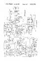
- FIG. 1is a circuit schematic diagram of the circuitry of the invention.
- FIG. 2is a circuit schematic diagram of a ring oscillator used in the circuit of FIG. 1.
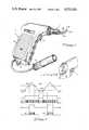
- FIG. 3is a perspective view of the electrothermal treatment apparatus in which the circuit of FIG. 1 is utilized.
- FIG. 3Ais another view of the apparatus of FIG. 3.
- FIG. 4is a diagram of several waveforms that are useful in illustrating the operation of the circuit of FIG. 1.
- Apparatus 3includes a momentary switch 11 which can be actuated by the index finger of a person gripping handle 5 to actuate circuit 1.
- a high frequency (approximately 2 Mhz) output voltage producedthereby appears across two spaced, electrically conductive electrically isolated probes 9A and 9B. If probes 9A and 9B are held against cancerous tissue in the eye of a livestock animal with adequate pressure, the resulting contact resistances will be sufficiently low that voltage between probes 9A and 9B causes a high frequency current to flow from one of the probes through the cancerous tissue into the other. This causes resistive heating of the cancerous tissue. As previously explained, the technique of treating "cancer eye" in cattle has been proven to be quite effective.
- Reference numeral 15 of FIG. 3designates a main switch that makes power supplied via an electrical connector 13 available to circuit 1 on conductor 21.
- Thermistor 17which is located in the tip of one of probes 9A and 9B, is connected between ground conductor 18 and conductor 19.
- the purpose of thermistor 17is to determine the temperature to which the cancerous tissue has been raised.
- Thermistor 17is connected in series with resistor 20, the upward end of which is connected to a supply voltage conductor 21 that has a potential of +V volts.
- Actuation of switch 11applies the voltage V in to conductor 21 to actuate circuit 1. (V in is made available by means of switch 15 of FIG. 3).
- the voltage on conductor 19is applied by means of a resistor 22B to the positive input of operational amplifier 22.
- Resistors 23 and 24are connected in series between +V and ground to produce a reference voltage on conductor 25.
- the voltage on conductor 25is applied by a resistor 22A to the negative input of operational amplifier 22, so that when the voltage on conductor 19 exceeds the reference voltage on conductor 25, the output of operational amplifier 22 goes to a high level.
- operational amplifiers 22, 26, 40 and 46 of FIG. 1can be implemented by means of an LM324N integrated circuit quad operational amplifier.
- the output of operational amplifier 22is connected to the negative input of operational amplifier 26.
- the positive input of operational amplifier 26is connected to the junction between resistors 27 and 29, which are connected in series between +V and ground to establish a switching point for operational amplifier 26 that corresponds to a thermistor temperature of 50° C.
- the output of operational amplifier 26is coupled to the base of NPN transistor 30, the collector of which is connected to +V, its emitter being connected to conductor 31.
- Conductor 31is connected to the reset input of a "555" integrated circuit timer, which is widely available.
- the 555 timeris designated by reference numeral 32, and is connected as shown to provide a two second oscillation frequency at its output on conductor 33.
- Light emitting diode 37is also connected to conductor 33, and blinks in synchronization with oscillation of timer 32 at a two second repetition rate.
- VCO circuit 39includes operational amplifier 40, the negative input of which is connected by resistor 41 to conductor 38. Resistor 42 connects the output of operational amplifier 40 back to the negative input thereof.
- the positive input of operational amplifier 40is connected to conductor 43 which, in turn, is connected to the junction between resistors 44 and 45. Resistors 44 and 45 are connected in series between +V and ground.
- the positive of input of operational amplifier 46is connected by resistor 47 to conductor 43 and is also connected to the junction 48 between the cathode of diode 49 and the anode of diode 50.
- the output of operational amplifier 46is connected by resistor 51 to conductor 52, which is one of the outputs of VCO circuit 39.
- the anode of diode 49is connected by resistor 53 to the output of operational amplifier 40.
- the cathode of diode 50is connected by resistor 54 to conductor 38.
- Conductor 48is connected by resistor 55 to conductor 52.
- the negative input of operational amplifier 46is connected to conductor 56, which is a second output of VCO circuit 39.
- Conductor 56is connected by resistor 57 to conductor 52 and also is connected by capacitor 58 to conductor 43.
- VCO circuit 39produces a triangular waveform signal on conductor 56 and a square wave signal on conductor 52, and that the frequency on both such waveforms is proportional to the voltage on conductor 38 and hence to the temperature of thermistor 17.
- the square wave signal on conductor 52is applied to the base of NPN transistor 59, the collector of which is connected to +V and the emitter of which is connected to conductor 36 to thereby apply an audio frequency signal to one input of audio transducer 34.
- the pitch of the sound emitted by audio transducer 34is proportional to the temperature of transducer 17.
- the triangular waveshape produced on conductor 56is applied to the negative input of operational amplifier 60, which functions as a comparator in this case.
- operational amplifiers 60, 79, 87 and 92also can be implemented by means of LM324N integrated circuit quad op amps. Note also that the op amps can be connected to function as comparators.
- the triangular waveform on conductor 56is compared with the DC voltage on conductor 61, which is connected to the positive input of comparator 60 to establish the switching point of comparator 60.
- the output of comparator 60is connected to conductor 62, which is coupled by resistor 63 to the base of NPN transistor 64.
- the base of transistor 64is connected by resistor 65 to ground.
- the emitter of transistor 64is connected to ground, and the collector is connected to a duty cycle control input of a ring oscillator circuit 66.
- oscillator 66is set to oscillate at approximately 2 megahertz. It has a duty cycle control input connected to conductor 67 which halts the oscillation when that input is at a logical "0". Conductor 67 is connected to the collector of transistor 64. The signal produced on conductor 67 in effect modulates the "duty cycle" of the two megahertz bursts produced on output conductors 68 and 69 of ring oscillator circuit 66. Conductor 68 is connected to the input of an inverter-driver circuit 70, the output of which is connected to the gate electrode of a VMOS power field effect transistor 71.
- the source electrode of VMOS transistor 71is connected to ground, and its drain electrode is connected to one primary terminal of transformer 72.
- Conductor 69is connected to the input of inverter-driver 73, the output of which is connected to the gate electrode of VMOS power transistor 74.
- the source electrode of transistor 74is connected to ground and its drain electrode is connected to the other primary winding terminal of transformer 72.
- a center tap electrode 75 of the primary winding of transformer 72is coupled by inductor 76 to +V conductor 21.
- Capacitor 78is connected between center tap 75 and ground.
- the terminals of the secondary winding of transformer 72are connected by conductors 77A and 77B to probes 9A and 9B, respectively, of electrothermal apparatus 3 of FIG. 3.
- Circuitry 102performs the function of regulating the duty cycle control signal applied to oscillator 66 to maintain the temperature of the cancerous or tumerous tissue in the range between 50° C. and 55° C.
- the threshold level applied by conductor 61 to the positive input of comparator 60normally represents the temperature of thermistor 17 in the range from 50° C. to 55° C., so that the "duty cycle" of the two megahertz voltage applied to probes 9A and 9B is automatically varied to keep it in the range between 50° and 55° C.
- operational amplifier 79has its output connected by conductor 61 to the negative input of comparator 60.
- the negative input of comparator 79is connected by means of capacitor 80 to conductor 61.
- comparator 79also is connected to conductor 81, which is connected to the junction between resistors 82 and 83. Resistors 82 and 83 are connected in series between +V and ground. Conductor 81 is also connected to the junction between resistor 84 and capacitor 85, the other terminal of resistor 84 being connected to conductor 62 and the other terminal of capacitor 85 being connected to ground.
- the positive input of operational amplifier 79is connected to conductor 86.
- Conductor 38previously referred to, is connected by resistor 87A to the input of operational amplifier 87.
- the positive input of operational amplifier 87is connected to the junction between resistors 88 and 89, which are connected in series between +V and ground.
- the output of operational amplifier 87is connected by resistor 90 to conductor 86 and by resistor 91 to the negative input thereof.
- the immediately foregoing circuitryperforms a "scaling" function on the voltage produced in response to thermistor 17 by operational amplifier 22 in order to produce a scaled voltage representative of the temperature of thermistor 17 in the range from 50° to 55° C. on conductor 86.
- Circuitry 106performs the function of causing circuitry 102 to impose a reduced "duty cycle" of approximately 50% on the duty cycle control signal applied to oscillator 66 for the first 8 seconds that power is applied to circuit 1.
- Reference numeral 92designates a comparator having its positive input connected to the junction between resistors 93 and 94, which are connected in series between +V and ground to establish a reference voltage equal to approximately two-thirds of the value of +V.
- the negative input of comparator 92is connected to the junction between resistor 95 and capacitor 96, which are connected in series between +V and ground to produce a slowly rising signal when +V volts is applied to conductor 21 in response to closing of switch 11.
- comparator 92The output of comparator 92 is coupled by resistor 97 to the anode of diode 98, the cathode of which is connected to conductor 86.
- the immediately foregoing circuitcooperates with circuitry 102 to limit the "duty cycle" of oscillator 66 to approximately 50% for the first eight seconds after switch 11 is actuated.
- comparator 92produces a high output voltage by forward biasing diode 98 and establishes a switchpoint at the positive input of comparator 79. This switchpoint voltage is determined by the value of resistors 97 and 92A and by the forward voltage drop of diode 98.
- circuit 1The operation of circuit 1 will now be explained with reference to the waveforms of FIG. 4.
- the temperature of the tissuewill begin to rise quite rapidly. As the temperature of the tissue rises, the temperatures of probes 9A and 9B also rise, although with a slight lag in time which may vary from a fraction of a second to more than one second.
- the temperature of thermistor 17is almost exactly equal to the temperature of the one of probes 9A and 9B in which it is disposed.
- the circuit within block 99amplifies the voltage across thermistor 17, producing a voltage on conductor 38 which is proportional to the thermistor temperature. When the thermistor temperature reaches approximately 50° C., the voltage on conductor 38 exceeds the threshold voltage applied to the positive input of comparator 26. Comparator 26 then switches, causing transistor 30 to apply an enable input to timer 32, enabling it to function as an astable multi-vibrator with a two second period on its output 33.
- VCO circuit 39begins to oscillate at an audio frequency that increases at a rate that is proportional to the increase in the voltage on conductor 38.
- VCO circuit 39produces a square wave signal on conductor 36 which is applied via capacitor 35 to one terminal of audio transducer 34.
- the voltage on conductor 33is at +V. (Switch 11, of course, is closed.)
- the square wave produced on conductor 36is smoothed somewhat by capacitor 35 and resistor 35', producing a relatively pure sinusoidal waveform of gradually increasing pitch across transducer 34, causing an audible sound of increasing pitch to be emitted by transducer 34.
- the range of audio frequencies of the soundis roughly 1 kilohertz to 4 kilohertz.
- the user of electrothermal apparatus 3knows that as long as the pitch of the sound emitted by transducer 34 continues to increase at a proper rate, he is maintaining adequate pressure of contact surfaces 9A' and 9B' against the cancerous tissue because its temperature is increasing at the same rate as the pitch of the sound emitted by transducer 34. If adequate contact is momentarily lost due, for example, to the struggling of the animal, the user realizes this immediately, because the pitch of the sound emitted by transducer 34 immediately stops increasing, and may, in fact, begin decreasing if the temperature of thermistor 17 begins to fall sharply due to loss of adequate probe surface contact with the cancerous tissue.
- the temperature of thermistor 17When adequate pressure of the probe contact surface has been maintained with the cancerous tissue for a sufficiently long period of time (typically approximately 10 seconds) the temperature of thermistor 17 will reach 50° C., and the voltage on conductor 33 produced by timer 32 will begin to rise and fall with a two second repetition rate, thereby periodically interrupting the ground return connection of ceramic transducer 34, so that the sound emitted thereby beeps at a two second repetition rate. As long as the temperature of the tissue is at least 50° C., the beeping will continue and the user can count the number of beeps until 15 of them have occurred, indicating that the cancerous tissue has been held at least 50° C. for at least 30 seconds. At this point, the probes can be removed and switch 11 can be released.
- the circuit of FIG. 1automatically regulates the temperature of the cancerous tissue, i.e., of thermistor 17, by modulating the "duty cycle" of the two megahertz current conducted via probes 9A and 9B to the cancerous tissue.
- ring oscillator 66produces two non-overlapping square wave signals on conductor 68 and 69. These square wave signals are buffered by driver circuits 70 and 73, respectively, which alternately turn VMOS power transistors 71 and 74 on and off in such a manner that at no time are both transistor 71 and 74 on simultaneously.
- VMOS power transistors 71 and 74can be the IRF523 or higher voltage IRF522 transistors manufactured by International Rectifier Corporation).
- the repetition rate of the switching of each of power transistors 71 and 74is approximately two megahertz.
- the modulation signal produced on conductor 67varies the "duty cycle" of the two megahertz "burst" applied to the primary winding of transformer 72 to keep the temperature of thermistor 17 in the range from 50° C. to 55° C.
- waveform 100illustrates the bursts of two megahertz current applied through probes 9A and 9B at a relatively high "duty cycle" corresponding to a thermistor temperature at the low end of the range from 50° C.
- waveform 101represents a relatively low duty cycle of the bursts of two megahertz current that would be produced by the automatic duty cycle regulating circuit represented by reference numeral 102 in FIG. 1 for a thermistor temperature at the high end of the range from 50° C. to 55° C.
- duty cyclerefers to the duty cycle of the "envelope" of the bursts of 2 MHz current, and not to each individual cycle of the 2 MHz current.
- the true duty cycle of each cycle of the 2 MHz currentalso could be varied to regulate the power delivered to the cancerous tissue.
- reference numeral 103represents the above-mentioned triangular waveform produced by VCO circuit 39 on conductor 56.
- Dotted line 104represents a relatively high threshold or trip point of comparator 79, applied as a voltage on conductor 86 for a relatively high thermistor temperature near 55° C.
- the output of comparator 60produces a signal that drives transistor 64 and starts two megahertz oscillator circuit 66, resulting in the two megahertz burst of pulses represented by reference numeral 101; this burst lasts as long as the triangular wave shape 103 is above threshold 104.
- thermistor temperatureis at the low end of the range from 50° C. to 55° C.
- a higher "duty cycle" of the current burstsis needed to pump more two megahertz current into the cancerous tissue, and a lower threshold voltage will appear on conductor 86.
- This lower threshold voltageis represented by dotted line 105 in FIG. 4, and comparator 60 functions as described above to produce wider bursts of two megahertz current, such as the ones indicated by reference numeral 100 in FIG. 4.
- the thermal lag in the temperature of the probe in which thermistor 17 is disposed relative to the rapidly rising temperature of the cancerous tissue during the initial period immediately after switch 11 is closedcan result in temperature "over-shoot" of the cancerous tissue to the extent that healthy eye tissue may be damaged.
- the inventionprovides the above-mentioned automatic initial eight second period in which the duty cycle of the two megahertz current is limited to 50% for the first eight seconds of operation. This ensures that the temperature of thermistor 17 rises nearly as fast as the temperature of the cancerous tissue, thereby ensuring that the temperature sensed by thermistor 17 accurately represents the temperature of the cancerous tissue.
- circuit 1operates to produce a slowly rising waveform that is applied to the negative input of comparator 92, beginning at the instant that switch 11 is closed.
- Current through resistor 95charges up capacitor 96 to produce this signal which, when it equals a voltage of approximately two thirds of +V (which typically is approximately 8 volts), causes the output of comparator 92 to fall and go to zero volts.
- This reverse biases diode 98allowing the voltage on conductor 86 to be determined by operational amplifier 87, which scales the temperature sensitive voltage produced by thermistor sensing circuit 99. Therefore, after the eight second delay time has elapsed, circuit 1 functions as previously described.
- comparator 60compares the triangular waveform 103 (FIG. 4) with the output of operational amplifier 79, which is produced on conductor 61.
- the positive input of operational amplifier 79is connected to conductor 86. (Recall that the voltage on conductor 86 is equal to the voltage at the junction between resistors 97 and 92A in circuit 106 for approximately the first eight seconds of operation to force the duty cycle to be approximately 50%. After the first eight seconds of operation have elapsed, the voltage on conductor 86 is a scaled down voltage that is proportional to the temperature of thermistor 17.)
- the voltage on conductor 86is compared with the voltage on conductor 81 in duty cycle regulating circuit 102, since the latter voltage is applied to the negative input of operational amplifier 79, as operational amplifier 79 actually functions as a comparator in this circuit.
- the circuitry including resistor 84, capacitor 85, operational amplifier 79 and capacitor 80functions as an integrator which averages the voltage signal on conductor 62. If the temperature of thermistor 17 is above 50° C., or during the first eight seconds of operation, the voltage on conductor 62 will be a sequence of pulses, the duty cycle of which depends on the voltage on conductor 86. After the first eight seconds of operation, but before the temperature of thermistor 17 attains 50° C., the voltage on conductor 62 will be a logical "1", rather than a sequence of pulses. During this time, the voltage on conductor 81 is equal to the voltage on conductor 62.
- Operational amplifier 79compares the voltage on conductor 81 with the voltage conductor on 86, and forces the voltage on conductor 61 to be +V. That causes comparator 60 to force the voltage on conductor 62 to equal +V (i.e., to have a 100% duty cycle). However, once the duty cycle of the voltage produced on conductor 62 becomes less than 100%, (i.e., after the temperature of thermistor 17 exceeds 50° C.) then the above-mentioned integrating circuit averages that value. Then the operation of the duty cycle regulating circuit 102 is as follows. Operational amplifier 79 compares the average of the duty cycle voltage on conductor 62 with the voltage on conductor 86.
- operational amplifier 79sets the threshold on conductor 61 such that comparator 60 forces the average voltage on conductor 62 to be equal to the present reference voltage on conductor 86. This operation results in linear reduction of the duty cycle of the signal on conductor 62, and hence, on conductor 67, with respect to increasing temperature of thermistor 17 from approximately 50° C. to approximately 55° C.
- ring oscillator circuit 66The details of ring oscillator circuit 66 can be described with reference to FIG. 2, wherein it can be seen that the major components of ring oscillator 66 include two one-shot integrated circuits 107 and 108 (each of which can be implemented by means of 74123N integrated circuits.) They can be interconnected in the manner shown with resistors 109, 110, and 112 and capacitors 111 and 113 selected to produce a two megahertz oscillation frequency.
- This circuitis well known to those skilled in the art, and its operation need not be described, except to note that it produces two out-of-phase, two megahertz square wave signals on conductors 68 and 69 whenever conductor 67 is held high.
- An important advantage of the circuit described in FIG. 1relates to the use of high power VMOS transistors 71 and 74 to drive the primary winding of transformer 72.
- oscillator circuits used in electrothermal apparatus for treatment of eye cancerhave utilized a NPN bipolar transistor in a Collpitts oscillator or a Hartley oscillator to generate the two megahertz frequency.
- the bipolar power transistor of such circuitsis always at least slightly on, and therefore continuously conducts current. The highest magnitude of current occurs when the transistor is saturated, and a very large amount of power is dissipated as a result of this current flowing across the V sat voltage drop between the collector and the emitter of the bipolar NPN transistor. This has resulted in excessive waste of power.
- the electrothermal treatment apparatus used for treating eye cancer in cattlebe both portable and battery powered.
- the excess waste of power of the prior devicereduces the number of treatments that can be performed before the batteries need to be re-charged; the excessive power dissipation has also resulted in the handle of some prior devices becoming excessively hot.
- the described embodiment of the inventionprovides a 50% duty cycle for the first eight seconds to avoid temperature overshoots, it would be quite feasible to use some other approach, such as gradually increasing the duty cycle from an initial low level to high level.
- some government regulationsmust be complied with for apparatus and methods used for human medical treatment, it is believed that the described embodiment of the invention can be modified to effectively treat certain skin growths, such as warts, in humans.
Landscapes
- Health & Medical Sciences (AREA)
- Life Sciences & Earth Sciences (AREA)
- Surgery (AREA)
- Engineering & Computer Science (AREA)
- Veterinary Medicine (AREA)
- General Health & Medical Sciences (AREA)
- Public Health (AREA)
- Animal Behavior & Ethology (AREA)
- Nuclear Medicine, Radiotherapy & Molecular Imaging (AREA)
- Physics & Mathematics (AREA)
- Plasma & Fusion (AREA)
- Otolaryngology (AREA)
- Biomedical Technology (AREA)
- Heart & Thoracic Surgery (AREA)
- Medical Informatics (AREA)
- Molecular Biology (AREA)
- Wood Science & Technology (AREA)
- Zoology (AREA)
- Electrotherapy Devices (AREA)
Abstract
Description
Claims (17)
Priority Applications (3)
| Application Number | Priority Date | Filing Date | Title |
|---|---|---|---|
| US06/453,811US4531524A (en) | 1982-12-27 | 1982-12-27 | Circuit apparatus and method for electrothermal treatment of cancer eye |
| GB08325500AGB2132893B (en) | 1982-12-27 | 1983-09-23 | Apparatus for electrothermal treatment of cancerous or tumorous tissue |
| US06/708,007US4644955A (en) | 1982-12-27 | 1985-03-04 | Circuit apparatus and method for electrothermal treatment of cancer eye |
Applications Claiming Priority (1)
| Application Number | Priority Date | Filing Date | Title |
|---|---|---|---|
| US06/453,811US4531524A (en) | 1982-12-27 | 1982-12-27 | Circuit apparatus and method for electrothermal treatment of cancer eye |
Related Child Applications (1)
| Application Number | Title | Priority Date | Filing Date |
|---|---|---|---|
| US06/708,007ContinuationUS4644955A (en) | 1982-12-27 | 1985-03-04 | Circuit apparatus and method for electrothermal treatment of cancer eye |
Publications (1)
| Publication Number | Publication Date |
|---|---|
| US4531524Atrue US4531524A (en) | 1985-07-30 |
Family
ID=23802168
Family Applications (1)
| Application Number | Title | Priority Date | Filing Date |
|---|---|---|---|
| US06/453,811Expired - LifetimeUS4531524A (en) | 1982-12-27 | 1982-12-27 | Circuit apparatus and method for electrothermal treatment of cancer eye |
Country Status (2)
| Country | Link |
|---|---|
| US (1) | US4531524A (en) |
| GB (1) | GB2132893B (en) |
Cited By (53)
| Publication number | Priority date | Publication date | Assignee | Title |
|---|---|---|---|---|
| US4644955A (en)* | 1982-12-27 | 1987-02-24 | Rdm International, Inc. | Circuit apparatus and method for electrothermal treatment of cancer eye |
| US4685459A (en)* | 1985-03-27 | 1987-08-11 | Fischer Met Gmbh | Device for bipolar high-frequency coagulation of biological tissue |
| US4753248A (en)* | 1987-06-24 | 1988-06-28 | Duke University | Probe translation system for use in hyperthermia treatment |
| US4813412A (en)* | 1982-12-28 | 1989-03-21 | Ya-Man Ltd. | Automatic system for an epilator device |
| US4878493A (en)* | 1983-10-28 | 1989-11-07 | Ninetronix Venture I | Hand-held diathermy apparatus |
| US4887593A (en)* | 1989-01-26 | 1989-12-19 | Wiley Michael J | Method and apparatus for electrosurgically resectioning an equine soft palate to alleviate occlusion of the breathing passageway |
| US4920978A (en)* | 1988-08-31 | 1990-05-01 | Triangle Research And Development Corporation | Method and apparatus for the endoscopic treatment of deep tumors using RF hyperthermia |
| US5190037A (en)* | 1991-10-21 | 1993-03-02 | Adm Tronics Unlimited, Inc. | High-power corona discharge beam thermotherapy system |
| US5249575A (en)* | 1991-10-21 | 1993-10-05 | Adm Tronics Unlimited, Inc. | Corona discharge beam thermotherapy system |
| DE19717023A1 (en)* | 1997-04-23 | 1998-10-29 | Micronas Intermetall Gmbh | Device for treating malignant, tumorous tissue areas |
| US20030195501A1 (en)* | 1998-05-05 | 2003-10-16 | Sherman Marshall L. | RF ablation system and method having automatic temperature control |
| US20030220674A1 (en)* | 2002-03-15 | 2003-11-27 | Anderson Richard Rox | Methods and devices for selective disruption of fatty tissue by controlled cooling |
| WO2004083797A3 (en)* | 2003-03-14 | 2004-12-29 | Thermosurgery Technologies Inc | Hyperthermia treatment system |
| US6939346B2 (en) | 1999-04-21 | 2005-09-06 | Oratec Interventions, Inc. | Method and apparatus for controlling a temperature-controlled probe |
| US20050251120A1 (en)* | 2002-03-15 | 2005-11-10 | Anderson Richard R | Methods and devices for detection and control of selective disruption of fatty tissue during controlled cooling |
| US20050273091A1 (en)* | 2002-10-29 | 2005-12-08 | Cathrxptyltd | System for, and method of, heating a biological site in a patient's body |
| US20050288662A1 (en)* | 2004-06-23 | 2005-12-29 | Uchida Andy H | Electrosurgical generator |
| US20070049998A1 (en)* | 2005-05-18 | 2007-03-01 | Tyrell, Inc. | Treatment device and method for treating skin lesions through application of heat |
| US7655003B2 (en) | 2005-06-22 | 2010-02-02 | Smith & Nephew, Inc. | Electrosurgical power control |
| US7854754B2 (en) | 2006-02-22 | 2010-12-21 | Zeltiq Aesthetics, Inc. | Cooling device for removing heat from subcutaneous lipid-rich cells |
| US8192474B2 (en) | 2006-09-26 | 2012-06-05 | Zeltiq Aesthetics, Inc. | Tissue treatment methods |
| US8275442B2 (en) | 2008-09-25 | 2012-09-25 | Zeltiq Aesthetics, Inc. | Treatment planning systems and methods for body contouring applications |
| US8285390B2 (en) | 2007-08-21 | 2012-10-09 | Zeltiq Aesthetics, Inc. | Monitoring the cooling of subcutaneous lipid-rich cells, such as the cooling of adipose tissue |
| US8523927B2 (en) | 2007-07-13 | 2013-09-03 | Zeltiq Aesthetics, Inc. | System for treating lipid-rich regions |
| US8603073B2 (en) | 2008-12-17 | 2013-12-10 | Zeltiq Aesthetics, Inc. | Systems and methods with interrupt/resume capabilities for treating subcutaneous lipid-rich cells |
| US8676338B2 (en) | 2010-07-20 | 2014-03-18 | Zeltiq Aesthetics, Inc. | Combined modality treatment systems, methods and apparatus for body contouring applications |
| US8702774B2 (en) | 2009-04-30 | 2014-04-22 | Zeltiq Aesthetics, Inc. | Device, system and method of removing heat from subcutaneous lipid-rich cells |
| US20150194805A1 (en)* | 2012-08-03 | 2015-07-09 | Mitsubishi Electric Corporation | Numerical control apparatus |
| US9132031B2 (en) | 2006-09-26 | 2015-09-15 | Zeltiq Aesthetics, Inc. | Cooling device having a plurality of controllable cooling elements to provide a predetermined cooling profile |
| US9314368B2 (en) | 2010-01-25 | 2016-04-19 | Zeltiq Aesthetics, Inc. | Home-use applicators for non-invasively removing heat from subcutaneous lipid-rich cells via phase change coolants, and associates devices, systems and methods |
| US9545523B2 (en) | 2013-03-14 | 2017-01-17 | Zeltiq Aesthetics, Inc. | Multi-modality treatment systems, methods and apparatus for altering subcutaneous lipid-rich tissue |
| USD777338S1 (en) | 2014-03-20 | 2017-01-24 | Zeltiq Aesthetics, Inc. | Cryotherapy applicator for cooling tissue |
| US9844460B2 (en) | 2013-03-14 | 2017-12-19 | Zeltiq Aesthetics, Inc. | Treatment systems with fluid mixing systems and fluid-cooled applicators and methods of using the same |
| US9861421B2 (en) | 2014-01-31 | 2018-01-09 | Zeltiq Aesthetics, Inc. | Compositions, treatment systems and methods for improved cooling of lipid-rich tissue |
| US20190247082A1 (en)* | 2012-04-30 | 2019-08-15 | Ethicon Llc | Ultrasonic device for cutting and coagulating |
| US10383787B2 (en) | 2007-05-18 | 2019-08-20 | Zeltiq Aesthetics, Inc. | Treatment apparatus for removing heat from subcutaneous lipid-rich cells and massaging tissue |
| US10524956B2 (en) | 2016-01-07 | 2020-01-07 | Zeltiq Aesthetics, Inc. | Temperature-dependent adhesion between applicator and skin during cooling of tissue |
| US10555831B2 (en) | 2016-05-10 | 2020-02-11 | Zeltiq Aesthetics, Inc. | Hydrogel substances and methods of cryotherapy |
| US10568759B2 (en) | 2014-08-19 | 2020-02-25 | Zeltiq Aesthetics, Inc. | Treatment systems, small volume applicators, and methods for treating submental tissue |
| US10675176B1 (en) | 2014-03-19 | 2020-06-09 | Zeltiq Aesthetics, Inc. | Treatment systems, devices, and methods for cooling targeted tissue |
| US10682297B2 (en) | 2016-05-10 | 2020-06-16 | Zeltiq Aesthetics, Inc. | Liposomes, emulsions, and methods for cryotherapy |
| US10722395B2 (en) | 2011-01-25 | 2020-07-28 | Zeltiq Aesthetics, Inc. | Devices, application systems and methods with localized heat flux zones for removing heat from subcutaneous lipid-rich cells |
| US10765552B2 (en) | 2016-02-18 | 2020-09-08 | Zeltiq Aesthetics, Inc. | Cooling cup applicators with contoured heads and liner assemblies |
| US10935174B2 (en) | 2014-08-19 | 2021-03-02 | Zeltiq Aesthetics, Inc. | Stress relief couplings for cryotherapy apparatuses |
| US10952891B1 (en) | 2014-05-13 | 2021-03-23 | Zeltiq Aesthetics, Inc. | Treatment systems with adjustable gap applicators and methods for cooling tissue |
| US20210124319A1 (en)* | 2014-04-28 | 2021-04-29 | Covidien Lp | Systems and methods for determining an end of life state for surgical devices |
| US11076879B2 (en) | 2017-04-26 | 2021-08-03 | Zeltiq Aesthetics, Inc. | Shallow surface cryotherapy applicators and related technology |
| US11154418B2 (en) | 2015-10-19 | 2021-10-26 | Zeltiq Aesthetics, Inc. | Vascular treatment systems, cooling devices, and methods for cooling vascular structures |
| US11207123B2 (en) | 2018-11-16 | 2021-12-28 | Applied Medical Resources Corporation | Electrosurgical system |
| US11382790B2 (en) | 2016-05-10 | 2022-07-12 | Zeltiq Aesthetics, Inc. | Skin freezing systems for treating acne and skin conditions |
| US11446175B2 (en) | 2018-07-31 | 2022-09-20 | Zeltiq Aesthetics, Inc. | Methods, devices, and systems for improving skin characteristics |
| US11986421B2 (en) | 2006-09-26 | 2024-05-21 | Zeltiq Aesthetics, Inc. | Cooling devices with flexible sensors |
| US12070411B2 (en) | 2006-04-28 | 2024-08-27 | Zeltiq Aesthetics, Inc. | Cryoprotectant for use with a treatment device for improved cooling of subcutaneous lipid-rich cells |
Families Citing this family (10)
| Publication number | Priority date | Publication date | Assignee | Title |
|---|---|---|---|---|
| GB8825604D0 (en)* | 1988-11-02 | 1988-12-07 | Solar Wide Ind Ltd | Electrotherapeutic device |
| EP0424686A1 (en)* | 1989-10-27 | 1991-05-02 | Storz Instrument Company | Control system for ophthalmic surgical instruments |
| US5346491A (en)* | 1991-03-28 | 1994-09-13 | Sony Corporation | Feed device for bipolar electrodes for capsulotomy |
| AU2366092A (en)* | 1991-07-31 | 1993-03-02 | Mentor O&O, Inc. | Controlling operation of handpieces during ophthalmic surgery |
| US5910110A (en)* | 1995-06-07 | 1999-06-08 | Mentor Ophthalmics, Inc. | Controlling pressure in the eye during surgery |
| USD418916S (en) | 1998-09-16 | 2000-01-11 | Mentor Ophthalmics, Inc. | Tube set for surgical instrument |
| GB9911956D0 (en)* | 1999-05-21 | 1999-07-21 | Gyrus Medical Ltd | Electrosurgery system and method |
| US6853173B2 (en)* | 2002-01-25 | 2005-02-08 | Broadcom Corporation | Programmable dual mode hysteretic power output controller |
| ITRE20090043A1 (en)* | 2009-04-30 | 2010-11-01 | Genesis Elettronica S R L | DEVICE FOR RADIOTHERAPY |
| US10729484B2 (en)* | 2013-07-16 | 2020-08-04 | Covidien Lp | Electrosurgical generator with continuously and arbitrarily variable crest factor |
Citations (5)
| Publication number | Priority date | Publication date | Assignee | Title |
|---|---|---|---|---|
| US4016886A (en)* | 1974-11-26 | 1977-04-12 | The United States Of America As Represented By The United States Energy Research And Development Administration | Method for localizing heating in tumor tissue |
| US4074719A (en)* | 1975-07-12 | 1978-02-21 | Kurt Semm | Method of and device for causing blood coagulation |
| US4124030A (en)* | 1977-01-05 | 1978-11-07 | Roberts Wallace A | Electro-therapeutic faradic current generator |
| US4189685A (en)* | 1978-03-14 | 1980-02-19 | The United States Of America As Represented By The United States Department Of Energy | Self-protecting transistor oscillator for treating animal tissues |
| US4237898A (en)* | 1978-03-27 | 1980-12-09 | Critical Systems, Inc. | Apparatus for heating tissue and employing protection against transients |
- 1982
- 1982-12-27USUS06/453,811patent/US4531524A/ennot_activeExpired - Lifetime
- 1983
- 1983-09-23GBGB08325500Apatent/GB2132893B/ennot_activeExpired
Patent Citations (5)
| Publication number | Priority date | Publication date | Assignee | Title |
|---|---|---|---|---|
| US4016886A (en)* | 1974-11-26 | 1977-04-12 | The United States Of America As Represented By The United States Energy Research And Development Administration | Method for localizing heating in tumor tissue |
| US4074719A (en)* | 1975-07-12 | 1978-02-21 | Kurt Semm | Method of and device for causing blood coagulation |
| US4124030A (en)* | 1977-01-05 | 1978-11-07 | Roberts Wallace A | Electro-therapeutic faradic current generator |
| US4189685A (en)* | 1978-03-14 | 1980-02-19 | The United States Of America As Represented By The United States Department Of Energy | Self-protecting transistor oscillator for treating animal tissues |
| US4237898A (en)* | 1978-03-27 | 1980-12-09 | Critical Systems, Inc. | Apparatus for heating tissue and employing protection against transients |
Cited By (99)
| Publication number | Priority date | Publication date | Assignee | Title |
|---|---|---|---|---|
| US4644955A (en)* | 1982-12-27 | 1987-02-24 | Rdm International, Inc. | Circuit apparatus and method for electrothermal treatment of cancer eye |
| US4813412A (en)* | 1982-12-28 | 1989-03-21 | Ya-Man Ltd. | Automatic system for an epilator device |
| US4878493A (en)* | 1983-10-28 | 1989-11-07 | Ninetronix Venture I | Hand-held diathermy apparatus |
| US4685459A (en)* | 1985-03-27 | 1987-08-11 | Fischer Met Gmbh | Device for bipolar high-frequency coagulation of biological tissue |
| US4753248A (en)* | 1987-06-24 | 1988-06-28 | Duke University | Probe translation system for use in hyperthermia treatment |
| US4920978A (en)* | 1988-08-31 | 1990-05-01 | Triangle Research And Development Corporation | Method and apparatus for the endoscopic treatment of deep tumors using RF hyperthermia |
| US4887593A (en)* | 1989-01-26 | 1989-12-19 | Wiley Michael J | Method and apparatus for electrosurgically resectioning an equine soft palate to alleviate occlusion of the breathing passageway |
| US5190037A (en)* | 1991-10-21 | 1993-03-02 | Adm Tronics Unlimited, Inc. | High-power corona discharge beam thermotherapy system |
| US5249575A (en)* | 1991-10-21 | 1993-10-05 | Adm Tronics Unlimited, Inc. | Corona discharge beam thermotherapy system |
| DE19717023A1 (en)* | 1997-04-23 | 1998-10-29 | Micronas Intermetall Gmbh | Device for treating malignant, tumorous tissue areas |
| US6245057B1 (en) | 1997-04-23 | 2001-06-12 | Micronas Intermetall Gmbh | Device for treating malignant, tumorous tissue areas |
| DE19717023C2 (en)* | 1997-04-23 | 2003-02-06 | Micronas Gmbh | Device for treating malignant, tumorous tissue areas |
| US20030195501A1 (en)* | 1998-05-05 | 2003-10-16 | Sherman Marshall L. | RF ablation system and method having automatic temperature control |
| US6939346B2 (en) | 1999-04-21 | 2005-09-06 | Oratec Interventions, Inc. | Method and apparatus for controlling a temperature-controlled probe |
| US20070010861A1 (en)* | 2002-03-15 | 2007-01-11 | Anderson Richard R | Methods and devices for selective disruption of fatty tissue by controlled cooling |
| US9358149B2 (en) | 2002-03-15 | 2016-06-07 | The General Hospital Corporation | Systems for affecting subcutaneous lipid-rich cells, systems for removing heat from subcutaneous lipid-rich cells, and systems for reducing subcutaneous lipid-rich cells |
| US11590020B2 (en) | 2002-03-15 | 2023-02-28 | The General Hospital Corporation | Methods and devices for selective disruption of fatty tissue by controlled cooling |
| US20050251120A1 (en)* | 2002-03-15 | 2005-11-10 | Anderson Richard R | Methods and devices for detection and control of selective disruption of fatty tissue during controlled cooling |
| US20030220674A1 (en)* | 2002-03-15 | 2003-11-27 | Anderson Richard Rox | Methods and devices for selective disruption of fatty tissue by controlled cooling |
| US9649220B2 (en) | 2002-03-15 | 2017-05-16 | The General Hospital Corporation | Treatment systems for removing heat from subcutaneous lipid-rich cells |
| US8834547B2 (en) | 2002-03-15 | 2014-09-16 | The General Hospital Corporation | Treatment systems for removing heat from subcutaneous lipid-rich cells |
| US9308120B2 (en) | 2002-03-15 | 2016-04-12 | The General Hospital Corporation | Methods and devices for selective disruption of fatty tissue by controlled cooling |
| US8840608B2 (en) | 2002-03-15 | 2014-09-23 | The General Hospital Corporation | Methods and devices for selective disruption of fatty tissue by controlled cooling |
| US7367341B2 (en) | 2002-03-15 | 2008-05-06 | The General Hospital Corporation | Methods and devices for selective disruption of fatty tissue by controlled cooling |
| US7871410B2 (en)* | 2002-10-29 | 2011-01-18 | Cathrx Ltd | System for, and method of, heating a biological site in a patient's body |
| US20050273091A1 (en)* | 2002-10-29 | 2005-12-08 | Cathrxptyltd | System for, and method of, heating a biological site in a patient's body |
| US20090118802A1 (en)* | 2003-03-14 | 2009-05-07 | Thermosurgery Technologies, Inc. | Hyperthermia Treatment Systems and Methods |
| US20050015125A1 (en)* | 2003-03-14 | 2005-01-20 | Mioduski Paul C. | Hyperthermia treatment systems and methods |
| US8306629B2 (en)* | 2003-03-14 | 2012-11-06 | Thermosurgery Technologies, Inc. | Hyperthermia treatment systems and methods |
| WO2004083797A3 (en)* | 2003-03-14 | 2004-12-29 | Thermosurgery Technologies Inc | Hyperthermia treatment system |
| US7226447B2 (en) | 2004-06-23 | 2007-06-05 | Smith & Nephew, Inc. | Electrosurgical generator |
| US20050288662A1 (en)* | 2004-06-23 | 2005-12-29 | Uchida Andy H | Electrosurgical generator |
| US20070049998A1 (en)* | 2005-05-18 | 2007-03-01 | Tyrell, Inc. | Treatment device and method for treating skin lesions through application of heat |
| US8348934B2 (en) | 2005-06-22 | 2013-01-08 | Smith & Nephew, Inc. | Electrosurgical power control |
| US8052675B2 (en) | 2005-06-22 | 2011-11-08 | Smith & Nephew, Inc. | Electrosurgical power control |
| US8603082B2 (en) | 2005-06-22 | 2013-12-10 | Smith & Nephew, Inc. | Electrosurgical power control |
| US20100121317A1 (en)* | 2005-06-22 | 2010-05-13 | Smith & Nephew, Inc. | Electrosurgical Power Control |
| US7655003B2 (en) | 2005-06-22 | 2010-02-02 | Smith & Nephew, Inc. | Electrosurgical power control |
| US8337539B2 (en) | 2006-02-22 | 2012-12-25 | Zeltiq Aesthetics, Inc. | Cooling device for removing heat from subcutaneous lipid-rich cells |
| US7854754B2 (en) | 2006-02-22 | 2010-12-21 | Zeltiq Aesthetics, Inc. | Cooling device for removing heat from subcutaneous lipid-rich cells |
| US12070411B2 (en) | 2006-04-28 | 2024-08-27 | Zeltiq Aesthetics, Inc. | Cryoprotectant for use with a treatment device for improved cooling of subcutaneous lipid-rich cells |
| US9375345B2 (en) | 2006-09-26 | 2016-06-28 | Zeltiq Aesthetics, Inc. | Cooling device having a plurality of controllable cooling elements to provide a predetermined cooling profile |
| US8192474B2 (en) | 2006-09-26 | 2012-06-05 | Zeltiq Aesthetics, Inc. | Tissue treatment methods |
| US9132031B2 (en) | 2006-09-26 | 2015-09-15 | Zeltiq Aesthetics, Inc. | Cooling device having a plurality of controllable cooling elements to provide a predetermined cooling profile |
| US11986421B2 (en) | 2006-09-26 | 2024-05-21 | Zeltiq Aesthetics, Inc. | Cooling devices with flexible sensors |
| US11179269B2 (en) | 2006-09-26 | 2021-11-23 | Zeltiq Aesthetics, Inc. | Cooling device having a plurality of controllable cooling elements to provide a predetermined cooling profile |
| US11219549B2 (en) | 2006-09-26 | 2022-01-11 | Zeltiq Aesthetics, Inc. | Cooling device having a plurality of controllable cooling elements to provide a predetermined cooling profile |
| US10292859B2 (en) | 2006-09-26 | 2019-05-21 | Zeltiq Aesthetics, Inc. | Cooling device having a plurality of controllable cooling elements to provide a predetermined cooling profile |
| US11395760B2 (en) | 2006-09-26 | 2022-07-26 | Zeltiq Aesthetics, Inc. | Tissue treatment methods |
| US10383787B2 (en) | 2007-05-18 | 2019-08-20 | Zeltiq Aesthetics, Inc. | Treatment apparatus for removing heat from subcutaneous lipid-rich cells and massaging tissue |
| US11291606B2 (en) | 2007-05-18 | 2022-04-05 | Zeltiq Aesthetics, Inc. | Treatment apparatus for removing heat from subcutaneous lipid-rich cells and massaging tissue |
| US9655770B2 (en) | 2007-07-13 | 2017-05-23 | Zeltiq Aesthetics, Inc. | System for treating lipid-rich regions |
| US8523927B2 (en) | 2007-07-13 | 2013-09-03 | Zeltiq Aesthetics, Inc. | System for treating lipid-rich regions |
| US11583438B1 (en) | 2007-08-21 | 2023-02-21 | Zeltiq Aesthetics, Inc. | Monitoring the cooling of subcutaneous lipid-rich cells, such as the cooling of adipose tissue |
| US8285390B2 (en) | 2007-08-21 | 2012-10-09 | Zeltiq Aesthetics, Inc. | Monitoring the cooling of subcutaneous lipid-rich cells, such as the cooling of adipose tissue |
| US10675178B2 (en) | 2007-08-21 | 2020-06-09 | Zeltiq Aesthetics, Inc. | Monitoring the cooling of subcutaneous lipid-rich cells, such as the cooling of adipose tissue |
| US9408745B2 (en) | 2007-08-21 | 2016-08-09 | Zeltiq Aesthetics, Inc. | Monitoring the cooling of subcutaneous lipid-rich cells, such as the cooling of adipose tissue |
| US8275442B2 (en) | 2008-09-25 | 2012-09-25 | Zeltiq Aesthetics, Inc. | Treatment planning systems and methods for body contouring applications |
| US8603073B2 (en) | 2008-12-17 | 2013-12-10 | Zeltiq Aesthetics, Inc. | Systems and methods with interrupt/resume capabilities for treating subcutaneous lipid-rich cells |
| US9737434B2 (en) | 2008-12-17 | 2017-08-22 | Zeltiq Aestehtics, Inc. | Systems and methods with interrupt/resume capabilities for treating subcutaneous lipid-rich cells |
| US11224536B2 (en) | 2009-04-30 | 2022-01-18 | Zeltiq Aesthetics, Inc. | Device, system and method of removing heat from subcutaneous lipid-rich cells |
| US9861520B2 (en) | 2009-04-30 | 2018-01-09 | Zeltiq Aesthetics, Inc. | Device, system and method of removing heat from subcutaneous lipid-rich cells |
| US8702774B2 (en) | 2009-04-30 | 2014-04-22 | Zeltiq Aesthetics, Inc. | Device, system and method of removing heat from subcutaneous lipid-rich cells |
| US11452634B2 (en) | 2009-04-30 | 2022-09-27 | Zeltiq Aesthetics, Inc. | Device, system and method of removing heat from subcutaneous lipid-rich cells |
| US9844461B2 (en) | 2010-01-25 | 2017-12-19 | Zeltiq Aesthetics, Inc. | Home-use applicators for non-invasively removing heat from subcutaneous lipid-rich cells via phase change coolants |
| US9314368B2 (en) | 2010-01-25 | 2016-04-19 | Zeltiq Aesthetics, Inc. | Home-use applicators for non-invasively removing heat from subcutaneous lipid-rich cells via phase change coolants, and associates devices, systems and methods |
| US10092346B2 (en) | 2010-07-20 | 2018-10-09 | Zeltiq Aesthetics, Inc. | Combined modality treatment systems, methods and apparatus for body contouring applications |
| US8676338B2 (en) | 2010-07-20 | 2014-03-18 | Zeltiq Aesthetics, Inc. | Combined modality treatment systems, methods and apparatus for body contouring applications |
| US10722395B2 (en) | 2011-01-25 | 2020-07-28 | Zeltiq Aesthetics, Inc. | Devices, application systems and methods with localized heat flux zones for removing heat from subcutaneous lipid-rich cells |
| US20190247082A1 (en)* | 2012-04-30 | 2019-08-15 | Ethicon Llc | Ultrasonic device for cutting and coagulating |
| US11529164B2 (en)* | 2012-04-30 | 2022-12-20 | Cilag Gmbh International | Ultrasonic device for cutting and coagulating |
| US20150194805A1 (en)* | 2012-08-03 | 2015-07-09 | Mitsubishi Electric Corporation | Numerical control apparatus |
| US9509131B2 (en)* | 2012-08-03 | 2016-11-29 | Mitsubishi Electric Corporation | Numerical control apparatus |
| US9545523B2 (en) | 2013-03-14 | 2017-01-17 | Zeltiq Aesthetics, Inc. | Multi-modality treatment systems, methods and apparatus for altering subcutaneous lipid-rich tissue |
| US9844460B2 (en) | 2013-03-14 | 2017-12-19 | Zeltiq Aesthetics, Inc. | Treatment systems with fluid mixing systems and fluid-cooled applicators and methods of using the same |
| US10201380B2 (en) | 2014-01-31 | 2019-02-12 | Zeltiq Aesthetics, Inc. | Treatment systems, methods, and apparatuses for improving the appearance of skin and providing other treatments |
| US10806500B2 (en) | 2014-01-31 | 2020-10-20 | Zeltiq Aesthetics, Inc. | Treatment systems, methods, and apparatuses for improving the appearance of skin and providing other treatments |
| US10575890B2 (en) | 2014-01-31 | 2020-03-03 | Zeltiq Aesthetics, Inc. | Treatment systems and methods for affecting glands and other targeted structures |
| US9861421B2 (en) | 2014-01-31 | 2018-01-09 | Zeltiq Aesthetics, Inc. | Compositions, treatment systems and methods for improved cooling of lipid-rich tissue |
| US10912599B2 (en) | 2014-01-31 | 2021-02-09 | Zeltiq Aesthetics, Inc. | Compositions, treatment systems and methods for improved cooling of lipid-rich tissue |
| US11819257B2 (en) | 2014-01-31 | 2023-11-21 | Zeltiq Aesthetics, Inc. | Compositions, treatment systems and methods for improved cooling of lipid-rich tissue |
| US10675176B1 (en) | 2014-03-19 | 2020-06-09 | Zeltiq Aesthetics, Inc. | Treatment systems, devices, and methods for cooling targeted tissue |
| USD777338S1 (en) | 2014-03-20 | 2017-01-24 | Zeltiq Aesthetics, Inc. | Cryotherapy applicator for cooling tissue |
| US20210124319A1 (en)* | 2014-04-28 | 2021-04-29 | Covidien Lp | Systems and methods for determining an end of life state for surgical devices |
| US11630427B2 (en)* | 2014-04-28 | 2023-04-18 | Covidien Lp | Systems and methods for determining an end of life state for surgical devices |
| US10952891B1 (en) | 2014-05-13 | 2021-03-23 | Zeltiq Aesthetics, Inc. | Treatment systems with adjustable gap applicators and methods for cooling tissue |
| US10935174B2 (en) | 2014-08-19 | 2021-03-02 | Zeltiq Aesthetics, Inc. | Stress relief couplings for cryotherapy apparatuses |
| US10568759B2 (en) | 2014-08-19 | 2020-02-25 | Zeltiq Aesthetics, Inc. | Treatment systems, small volume applicators, and methods for treating submental tissue |
| US11154418B2 (en) | 2015-10-19 | 2021-10-26 | Zeltiq Aesthetics, Inc. | Vascular treatment systems, cooling devices, and methods for cooling vascular structures |
| US10524956B2 (en) | 2016-01-07 | 2020-01-07 | Zeltiq Aesthetics, Inc. | Temperature-dependent adhesion between applicator and skin during cooling of tissue |
| US10765552B2 (en) | 2016-02-18 | 2020-09-08 | Zeltiq Aesthetics, Inc. | Cooling cup applicators with contoured heads and liner assemblies |
| US10682297B2 (en) | 2016-05-10 | 2020-06-16 | Zeltiq Aesthetics, Inc. | Liposomes, emulsions, and methods for cryotherapy |
| US11382790B2 (en) | 2016-05-10 | 2022-07-12 | Zeltiq Aesthetics, Inc. | Skin freezing systems for treating acne and skin conditions |
| US10555831B2 (en) | 2016-05-10 | 2020-02-11 | Zeltiq Aesthetics, Inc. | Hydrogel substances and methods of cryotherapy |
| US11076879B2 (en) | 2017-04-26 | 2021-08-03 | Zeltiq Aesthetics, Inc. | Shallow surface cryotherapy applicators and related technology |
| US11446175B2 (en) | 2018-07-31 | 2022-09-20 | Zeltiq Aesthetics, Inc. | Methods, devices, and systems for improving skin characteristics |
| US12102557B2 (en) | 2018-07-31 | 2024-10-01 | Zeltiq Aesthetics, Inc. | Methods, devices, and systems for improving skin characteristics |
| US11207123B2 (en) | 2018-11-16 | 2021-12-28 | Applied Medical Resources Corporation | Electrosurgical system |
| US12082867B2 (en) | 2018-11-16 | 2024-09-10 | Applied Medical Resources Corporation | Electrosurgical system |
Also Published As
| Publication number | Publication date |
|---|---|
| GB8325500D0 (en) | 1983-10-26 |
| GB2132893B (en) | 1986-10-08 |
| GB2132893A (en) | 1984-07-18 |
Similar Documents
| Publication | Publication Date | Title |
|---|---|---|
| US4531524A (en) | Circuit apparatus and method for electrothermal treatment of cancer eye | |
| US4644955A (en) | Circuit apparatus and method for electrothermal treatment of cancer eye | |
| US3601126A (en) | High frequency electrosurgical apparatus | |
| US20190374284A1 (en) | Methods and systems related to an electrosurgical controller | |
| EP3572022B1 (en) | Electrosurgical medical device with power modulation | |
| US4878493A (en) | Hand-held diathermy apparatus | |
| US6939344B2 (en) | Method for controlling skin temperature during thermal treatment | |
| JP2018509264A (en) | Non-invasive skin treatment device using RF current with treatment setting determiner | |
| KR101272372B1 (en) | Device for treating skin | |
| EP1810630B1 (en) | System for terminating treatment in impedance feedback algorithm | |
| JP2011512227A (en) | Skin treatment device for personal use and method of using the same | |
| US20050273092A1 (en) | Method and apparatus for shrinking tissue | |
| US20040006337A1 (en) | Multi-channnel rf energy delivery with coagulum reduction | |
| US5782893A (en) | Neuromuscular electrical stimulator for deep vein thrombosis treatment | |
| JPH06500476A (en) | Temperature controlled RF coagulation | |
| KR102287415B1 (en) | The apparatus of rf treatment using rf-energy | |
| KR20030081388A (en) | Device for the electrothermal treatment of the human or animal body | |
| JP2019517843A5 (en) | Electrosurgical device for delivering RF and microwave energy and method of use thereof | |
| EP0024653A1 (en) | Apparatus for supplying power to an electrosurgical device | |
| KR101725371B1 (en) | High frequency electromagnetic wave and ultrasonic waver hyperthermia medical apparatus using single electrode | |
| US6461348B1 (en) | Photo-thermal epilation apparatus with advanced energy storage arrangement | |
| US20090125015A1 (en) | Electrolysis Hair-Removal Device | |
| US4550728A (en) | Epilator | |
| EP0188413B1 (en) | Circuit apparatus for electrothermal treatment of cancer eye | |
| JPS6246183B2 (en) |
Legal Events
| Date | Code | Title | Description |
|---|---|---|---|
| AS | Assignment | Owner name:HEDIN, GENE R. 4323 W. ORCHID LANE GLENDALE, AZ 8 Free format text:ASSIGNMENT OF ASSIGNORS INTEREST.;ASSIGNOR:MIODUSKI, PAUL;REEL/FRAME:004081/0875 Effective date:19821216 | |
| AS | Assignment | Owner name:RDM INTERNATIONAL, INC 8433 NORTH BLACK CANYON HIG Free format text:ASSIGNMENT OF ASSIGNORS INTEREST.;ASSIGNOR:HEDIN, GENE R.;REEL/FRAME:004368/0902 Effective date:19850228 | |
| STCF | Information on status: patent grant | Free format text:PATENTED CASE | |
| FEPP | Fee payment procedure | Free format text:PAYOR NUMBER ASSIGNED (ORIGINAL EVENT CODE: ASPN); ENTITY STATUS OF PATENT OWNER: SMALL ENTITY | |
| FPAY | Fee payment | Year of fee payment:4 | |
| FEPP | Fee payment procedure | Free format text:PAYOR NUMBER ASSIGNED (ORIGINAL EVENT CODE: ASPN); ENTITY STATUS OF PATENT OWNER: SMALL ENTITY Free format text:PAYER NUMBER DE-ASSIGNED (ORIGINAL EVENT CODE: RMPN); ENTITY STATUS OF PATENT OWNER: SMALL ENTITY | |
| FEPP | Fee payment procedure | Free format text:PAYER NUMBER DE-ASSIGNED (ORIGINAL EVENT CODE: RMPN); ENTITY STATUS OF PATENT OWNER: SMALL ENTITY | |
| FPAY | Fee payment | Year of fee payment:8 | |
| FEPP | Fee payment procedure | Free format text:PAYOR NUMBER ASSIGNED (ORIGINAL EVENT CODE: ASPN); ENTITY STATUS OF PATENT OWNER: SMALL ENTITY | |
| FPAY | Fee payment | Year of fee payment:12 |