US4529246A - Patient chair - Google Patents
Patient chairDownload PDFInfo
- Publication number
- US4529246A US4529246AUS06/248,852US24885281AUS4529246AUS 4529246 AUS4529246 AUS 4529246AUS 24885281 AUS24885281 AUS 24885281AUS 4529246 AUS4529246 AUS 4529246A
- Authority
- US
- United States
- Prior art keywords
- seat
- chair
- supporting
- arm
- members
- Prior art date
- Legal status (The legal status is an assumption and is not a legal conclusion. Google has not performed a legal analysis and makes no representation as to the accuracy of the status listed.)
- Expired - Lifetime
Links
Images


Classifications
- A—HUMAN NECESSITIES
- A47—FURNITURE; DOMESTIC ARTICLES OR APPLIANCES; COFFEE MILLS; SPICE MILLS; SUCTION CLEANERS IN GENERAL
- A47C—CHAIRS; SOFAS; BEDS
- A47C3/00—Chairs characterised by structural features; Chairs or stools with rotatable or vertically-adjustable seats
- A47C3/02—Rocking chairs
- A47C3/021—Rocking chairs having elastic frames
- A47C3/023—Rocking chairs having elastic frames made of tubular material
- A—HUMAN NECESSITIES
- A47—FURNITURE; DOMESTIC ARTICLES OR APPLIANCES; COFFEE MILLS; SPICE MILLS; SUCTION CLEANERS IN GENERAL
- A47C—CHAIRS; SOFAS; BEDS
- A47C3/00—Chairs characterised by structural features; Chairs or stools with rotatable or vertically-adjustable seats
- A47C3/02—Rocking chairs
- A—HUMAN NECESSITIES
- A47—FURNITURE; DOMESTIC ARTICLES OR APPLIANCES; COFFEE MILLS; SPICE MILLS; SUCTION CLEANERS IN GENERAL
- A47C—CHAIRS; SOFAS; BEDS
- A47C7/00—Parts, details, or accessories of chairs or stools
- A47C7/02—Seat parts
- A47C7/14—Seat parts of adjustable shape; elastically mounted ; adaptable to a user contour or ergonomic seating positions
- A—HUMAN NECESSITIES
- A47—FURNITURE; DOMESTIC ARTICLES OR APPLIANCES; COFFEE MILLS; SPICE MILLS; SUCTION CLEANERS IN GENERAL
- A47C—CHAIRS; SOFAS; BEDS
- A47C7/00—Parts, details, or accessories of chairs or stools
- A47C7/36—Supports for the head or the back
- A47C7/40—Supports for the head or the back for the back
- A47C7/46—Supports for the head or the back for the back with special, e.g. adjustable, lumbar region support profile; "Ackerblom" profile chairs
- A—HUMAN NECESSITIES
- A61—MEDICAL OR VETERINARY SCIENCE; HYGIENE
- A61G—TRANSPORT, PERSONAL CONVEYANCES, OR ACCOMMODATION SPECIALLY ADAPTED FOR PATIENTS OR DISABLED PERSONS; OPERATING TABLES OR CHAIRS; CHAIRS FOR DENTISTRY; FUNERAL DEVICES
- A61G5/00—Chairs or personal conveyances specially adapted for patients or disabled persons, e.g. wheelchairs
- A61G5/10—Parts, details or accessories
- A61G5/12—Rests specially adapted therefor, e.g. for the head or the feet
- A61G5/121—Rests specially adapted therefor, e.g. for the head or the feet for head or neck
- A—HUMAN NECESSITIES
- A61—MEDICAL OR VETERINARY SCIENCE; HYGIENE
- A61G—TRANSPORT, PERSONAL CONVEYANCES, OR ACCOMMODATION SPECIALLY ADAPTED FOR PATIENTS OR DISABLED PERSONS; OPERATING TABLES OR CHAIRS; CHAIRS FOR DENTISTRY; FUNERAL DEVICES
- A61G5/00—Chairs or personal conveyances specially adapted for patients or disabled persons, e.g. wheelchairs
- A61G5/10—Parts, details or accessories
- A61G5/12—Rests specially adapted therefor, e.g. for the head or the feet
- A61G5/125—Rests specially adapted therefor, e.g. for the head or the feet for arms
- Y—GENERAL TAGGING OF NEW TECHNOLOGICAL DEVELOPMENTS; GENERAL TAGGING OF CROSS-SECTIONAL TECHNOLOGIES SPANNING OVER SEVERAL SECTIONS OF THE IPC; TECHNICAL SUBJECTS COVERED BY FORMER USPC CROSS-REFERENCE ART COLLECTIONS [XRACs] AND DIGESTS
- Y10—TECHNICAL SUBJECTS COVERED BY FORMER USPC
- Y10S—TECHNICAL SUBJECTS COVERED BY FORMER USPC CROSS-REFERENCE ART COLLECTIONS [XRACs] AND DIGESTS
- Y10S297/00—Chairs and seats
- Y10S297/10—Occupant-arising assist
Definitions
- This inventionrelates to a chair which because of its characteristics and construction, as will be described, facilitates use by weakened, partially disabled, or infirm users suffering a variety of ailments in a manner constituting a distinct improvement over patient-type chairs of the prior art. Because of the comforts it provides, the chair of the invention also is appropriate for the seating needs of healthy users, and it is also a distinct improvement over chairs of the prior art for general seating use.
- One object of the inventionis to provide a chair which enables the user to utilize his strongest muscles (usually leg muscles) for rising up out of the chair.
- Another object of the inventionis to provide a chair which supports the user on a porous yet fully washable stratum which requires no additional stuffing, cushioning, or support materials, thus making the chair breathable, washable and fully drying.
- An object of the present inventionis to provide a chair which provides superior back comfort and head support adjustable within all but the extreme ranges of user sizes.
- An object of the present inventionis to provide a chair in which slight rocking motion can be achieved which provides an opportunity for exercise to the debilitated user; and which also allows the constant partial shifting and redistribution of body weight and helps the patient to dissipate institutionally and health-related anxieties by moving and rocking. Should decubitis already have set in, it is an object of the present invention to provide adequate air circulation to affected portions in order that they might heal.
- the prior art chairsas the user pushes downward on the fronts of armrests in order to lift himself upwardly, for the armrest fronts to rotate downwardly, opposite the direction in which the user is trying to push.
- Another object of the present inventionis to provide a chair with a rocking motion, the axis of which is located in front of the knees so that the knees and armrest fronts remain stable while the body rotates backward into the chair back; and one that has no tendency to rock forwardly when the user pushes down on the armrests to lift himself out of the chair.
- a further object of the present inventionis to provide a chair of minimum bulk with minimal use of materials that would fuel a fire and the structure of which absorbs initial impact by the user.
- Another problem addressed by the present inventionis that of stability in use, since many health care chairs have a tendency to tip forwards, sideways, or backwards under the varied conditions in which users try to enter and exit them.
- An object of the present inventionis to provide a chair which will be stable under all normal circumstances of use.
- a final problem encountered in the health care fieldare a variety of functions or treatments not normally performed in a lounge chair which must be performed or endured by a patient occasionally or intermittently while seated in the same chair.
- One such functionis eating, anoyther is urinating, another is the draining of body fluids into drainage bags, and still another is sitting upright or remaining seated under conditions of semiconsciousness or disorientation.
- a final object of the present inventionis to provide a chair which accepts a variety of optionally used fittings to accommodate this diverse range of needs.
- the objects of the present inventionare accomplished by providing a chair which is primarily intended for use by the weakened, parially disabled, or infirm user such as are typically found in hospitals, nursing homes, extended care facilities, and sickrooms, and which is directed primarily at the geriatric, orthopaedic, rehabilitating, psychiatric, and maternity patient.
- the chair as described aboveconsists of a tubular or barstock steel base frame vertical leg components of which support tubular or bar stock steel side frames which in turn support a web-like member.
- the web-like membermay be formed of a polyester mesh or other suitable washable material, and the chair is contructed so that the web-like member may be removed for replacement purposes.
- a major advantage of the chairis the placement and support of armrests. They are axially supported at their front end by a relatively rigid member so all downward force exerted at their front ends is resisted by the vertical legs of the chair acting as axial struts, thus providing the user a stable stratum against which to push for exiting the chair. Furthermore, these armrests extend well past the seat front, enabling the user to first pull himself far forward enough so that he is then pushing downwardly over the center of gravity of his feet enabling his leg muscles to perform a substantially higher proportion of the work than his arm and upper body msucles would otherwise have had to perform.
- this slingconsists of an open polyester mesh which provides both full ventilation to the user and complete washability.
- the amount of material requiredis so minimal, in fact, that it dries quickly without trapping water and contributes so little potential fuel that it is not subject to present flammability laws governing upholstered furniture.
- the chairis the seated comfort it provides.
- the front-cantilevered side framesdeflect rearwardly, leaning the user back into the chair with a slight but soothing rocking motion which further shifts concentration of the user's body weight to different tissue areas as his center of gravity shifts correspondingly back and forth. Since the point of fixing of the flexing cantilevered side frames is at their front end, the corresponding axis of rotation of side frames is just above and in front of the knees, which therefore remains relatively stable so there is no lifting off the floor of the user's feet.
- the properly-placed lumbar supportgives adequate support to the critical lumbar region, while the headrest can be adjusted up or down to correspond with the small of the neck within the range limited by its permanently sewn attachment straps via hook and loop tape fasteners. And as the user drops into the chair, the flexure of the side frames absorbs impact and prevents skeletal shock, for which heavy padding might otherwise be needed.
- Yet another advantage of the chairis that the portions of the base that are on the floor are sized large enough so that the user's center of gravity always falls within those boundaries delineated by the base, thus precluding any instability in normal use.
- the skeletal nature of the chair's structurepermits the attachment of a multitude of accessories to accommodate the treatments or functions not normally performed in a lounge chair.
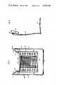
- FIG. 1is a perspective view of a patient's chair constructed in accordance with one embodiment of the invention
- FIG. 1Ais a fragmentary representation of a detail A of the chair of FIG. 1;
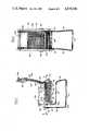
- FIG. 2is a side elevation of the chair of FIG. 1 with an upholstered pad placed on the chair;
- FIG. 3is a front elevation of the chair with the upholstered pad in place
- FIG. 4is a back elevation of the chair
- FIG. 5is a bottom view of the chair
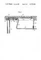
- FIG. 6is a side view of the upholstered pad which may be placed on the chair, if so desired;
- FIG. 7is a side on perspective view of a second embodiment of the invention.
- FIG. 8is a front view of the second embodiment
- FIG. 9is an enlarged sectional view of the arm assembly of the chair of the second embodiment, taken along the line 9--9 of FIG. 7;
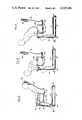
- FIG. 10is a side elevation of the chair of FIG. 7 under loading in normal use and
- FIG. 11is a side elevation showing how a user, having first pulled himself forward, can push vertically down over the center of his feet thus calling his leg muscles into play in rising out of the chair into a standing position.
- FIG. 12is a side elevation showing how a user completes his exit from the chair.
- the chair of the present inventionin the embodiment shown in FIGS. 1-6 includes a frame formed of a resilient member 10 which may be composed, for example, of tubular steel.
- the resilient memberis shaped to provide a base for the chair having two spaced and parallel side sections 12 and a transverse section 14.
- the tubular member 10also forms two spaced and parallel legs 16 at the forward end of the chair, and two spaced and parallel side members 18 which constitute a seat-supporting section of the chair, as well as two spaced and converging side members 20 which constitute a back supporting section of the chair.
- the tubular members 12 and 16form an open front so that an ottoman may be slid under and stored below the chair.
- the side members 18are configured so that there is a slight inclination of the seat away from the front of the chair when the weight is removed, to assist the patient in getting out of the chair.
- a tubular transverse member 22is removably received in the ends of the side members 20.
- a web-like member 24is supported on the frame to constitute the seat and back of the chair.
- the web-like memberis sewn or otherwise attached to a marginal fabric 42.
- the web-like member and marginal fabricform a sheath for receiving the converging side members 20 of the back supporting section of the chair.
- the web-like member 24may be formed, for example, of polyester mesh.
- the tubular transverse member 22is removable, to permit the web-like member 24 and marginal fabric 42 to be removed from the frame for washing or replacement purposes.
- the member 22is bent back into a concave shape, as best shown in FIG. 2, to prevent the patient from hitting his head.
- the tubular member 10is configured to provide a pair of approximately U-shaped, or C-shaped, sections 30 at the respective junctions between the forward ends of side members 18 and legs 16.
- the sections 30by the nature of their geometry increase the flex and period of flex of the seat of the chair under load, and distribute stresses along their length.
- a pair of arm rests 32are affixed at their forward ends to the U-shaped sections 30, the arm rests being formed of an appropriate rigid material such as wood or plastic.
- the arm restsextend a substantial distance beyond the front edge of the seat to permit the patient to grasp the ends of the arm rests to push himself out of the seat.
- U-shaped transverse members 36 and 38are attached to the forward and rear ends, respectively, of the side members 18 for reinforcing purposes.
- a head rest 39which may be in the form of an upholstered cushion, is hung on the back of the chair by straps 40, or other appropriate fastenings.
- the upright front members 16preferably diverge towards the base so that when the arm rests are removed the chairs may be nested and stacked for more compact shipping and storage.
- the portion of the web-like member 24 forming the seat of the chairis supported on the frame by a series of springs 46 which extend between a marginal fabric sewn to the side edges of the web-like member under the seat, and the marginal fabric 42 which is folded around and under the side members 18.
- a pair of members 44formed of plastic or other appropriate material are attached to the tubular member 10 at the respective junctions between the side sections 12 and front legs 16 to prevent the chair from having any tendency to tip over in a forward direction.
- a pad 50in the form of an upholstered cushion covered with vinyl, or other appropriate material, may be provided which can be used with the chair, as shown in FIGS. 2 and 3, although the use of such a pad is not essential.
- the padis equipped with Velcro fasteners which engage the Velcro strips 48 to hold the pad on the chair.
- Pad 50is equipped with a head rest 52 which is attached to the pad by straps 54.
- the chairincludes a base formed, for example, of tubular steel.
- the basehas two spaced and parallel side sections 112, a transverse section 114, and two spaced and parallel upright legs 116 at the forward end thereof.
- the upper end of each of the legs 116is welded to an elongated flat plate 121 which may be formed of flat high-strength steel bar stock.
- the steel platesprovide mounting for two spaced and parallel side members 118 which constitute the seat supporting section of the chair, and two spaced and converging side members 120 which constitute the back supporting section of the chair.
- the steel members 118, 120are held spaced apart in position by three transverse bars 136, 138 and 140.
- the two seat-supporting side members 118also each has a forward Z-shaped section 119 which, as shown in FIGS. 7 and 9 extends upwardly from the corresponding side member 118 and under a corresponding arm rest 132.
- the side members 118 and 120, and section 119, and strip 123 on each side of the chairconstitute a cantilevered leaf-spring assembly capable of being deflected with respect to leg 116 through a substantial range without permanent distortion or set.
- These memberslikewise may be formed of flat steel barstock, heat treated to have spring action mechanical properties.
- the forward end of each section 119extends between a steel plate 121 welded to the upper end of leg 116, and an L-shaped steel strip 123.
- the purpose of the L-shaped steel strip 123is to pull down the rear end of the arm rest 132 when the seat is deflected downwardly and to give added strength to the seat-supporting member 118 so that the combination of members will have additional load-bearing capacity.
- Soft rubber spacers 125 and 127are provided between the plate 121 and section 119 in order to enhance the apparent resiliency of member 118 and to prevent the sharp upper rear corner of member 121 from creating a point of concentrated stress on member 118 at their point of contact.
- Section 119is secured to plate 121 by a bolt 129, and the rear end of strip 123 is secured to member 118 by a bolt 131 which is received in a threaded sleeve 133 welded into the end of strip 123.
- Arm rest 132is held in place at its rear end by a nut and bolt 135, the head of which is embedded in the armrest, and at its front end by overlapping the section 119 and strip 123.
- a bolt 145limits the motion of section 119 relative to plate 121 in order to preclude pulling the head off bolt 129, and to keep member 118 and plate 121 in parallel alignment.
- the front of the armrestmay be pulled over and disengaged from section 119 and strip 123, giving access to the head of bolt 129. Tightening or loosening the bolt 129 against the soft rubber spacers 125, 127 adjusts the angle of inclination of member 118 (the inclination of the seat) to accommodate more exactly to various patient weights by increasing the height or the rear of the seat for heavier patients.
- the assembly described aboveprovides a strong support for the seat of the chair and yet provides for a resilient rocking action by the occupant.
- the members 112 and 116form an open front so that an ottoman may be slid and stored under the chair.
- a web-like member 124wraps around and is supported on the side members 118 and 120 to constitute the seat and back of the chair.
- a marginal fabric 142receives the side members and serves as a decorative trim. The marginal fabric is sewn over the web-like member.
- the web-like member 124as in the previous embodiment, may be formed of polyester mesh, and it is removable for washing purposes.
- a head cushion 152is adjustably attached to the web-like member 124 by appropriately sewn and located limiting straps and hook and loop fastener tape.
- a pair of members 144, formed of plastic or other appropriate materialare attached to the forward end of the base, as shown, to prevent forward tipping of the chair and to prevent the chair from sliding when the patient is getting up out of the chair.
- a padsimilar to the pad 50 of FIG. 6 may be provided for use with the chair of FIGS. 7, 8 and 9.
- the forward edge of the seatis displaced rearwardly of the legs 116 by a substantial amount to assist the sitter in getting out of the chair because by pressing down on the forward ends of the arm rests 132 against the top of the rigid legs 116 he is pushing axially over the lower part of his legs and the center of gravity of his feet, bringing his leg muscles into play in rising out of the chair, as shown in FIGS. 10-12.
- the inventionprovides, therefore, a relatively inexpensive patient's chair which is light and sturdy; which is eminently comfortable; which uses breathable and washable material; which provides a smooth, soothing rocking action; which minimizes skeletal shock to the patient upon impact when sitting down in the chair; which allows the sitter to rock backwards and forwards without his or her feet leaving the floor, and which above all is easy for the patient to get out of.
Landscapes
- Health & Medical Sciences (AREA)
- Life Sciences & Earth Sciences (AREA)
- Animal Behavior & Ethology (AREA)
- General Health & Medical Sciences (AREA)
- Public Health (AREA)
- Veterinary Medicine (AREA)
- Otolaryngology (AREA)
- Special Chairs (AREA)
- Chairs Characterized By Structure (AREA)
- Chairs For Special Purposes, Such As Reclining Chairs (AREA)
Abstract
Description
Claims (26)
Priority Applications (4)
| Application Number | Priority Date | Filing Date | Title |
|---|---|---|---|
| US06/248,852US4529246A (en) | 1980-01-07 | 1981-03-30 | Patient chair |
| CA000399758ACA1201051A (en) | 1981-03-30 | 1982-03-30 | Patient chair |
| AU82150/82AAU549263B2 (en) | 1981-03-30 | 1982-03-30 | Chair |
| US06/368,521US4595235A (en) | 1981-03-30 | 1982-04-15 | Patient's defined-motion chair |
Applications Claiming Priority (2)
| Application Number | Priority Date | Filing Date | Title |
|---|---|---|---|
| US11034080A | 1980-01-07 | 1980-01-07 | |
| US06/248,852US4529246A (en) | 1980-01-07 | 1981-03-30 | Patient chair |
Related Parent Applications (1)
| Application Number | Title | Priority Date | Filing Date |
|---|---|---|---|
| US11034080AContinuation-In-Part | 1980-01-07 | 1980-01-07 |
Related Child Applications (1)
| Application Number | Title | Priority Date | Filing Date |
|---|---|---|---|
| US06/368,521Continuation-In-PartUS4595235A (en) | 1981-03-30 | 1982-04-15 | Patient's defined-motion chair |
Publications (1)
| Publication Number | Publication Date |
|---|---|
| US4529246Atrue US4529246A (en) | 1985-07-16 |
Family
ID=22940956
Family Applications (2)
| Application Number | Title | Priority Date | Filing Date |
|---|---|---|---|
| US06/248,852Expired - LifetimeUS4529246A (en) | 1980-01-07 | 1981-03-30 | Patient chair |
| US06/368,521Expired - LifetimeUS4595235A (en) | 1981-03-30 | 1982-04-15 | Patient's defined-motion chair |
Family Applications After (1)
| Application Number | Title | Priority Date | Filing Date |
|---|---|---|---|
| US06/368,521Expired - LifetimeUS4595235A (en) | 1981-03-30 | 1982-04-15 | Patient's defined-motion chair |
Country Status (3)
| Country | Link |
|---|---|
| US (2) | US4529246A (en) |
| AU (1) | AU549263B2 (en) |
| CA (1) | CA1201051A (en) |
Cited By (23)
| Publication number | Priority date | Publication date | Assignee | Title |
|---|---|---|---|---|
| US4784435A (en)* | 1986-02-26 | 1988-11-15 | Leib Roger K | Patient chair |
| US4946224A (en)* | 1988-03-21 | 1990-08-07 | Leib Roger K | Combination wood-metal chair |
| US5020817A (en)* | 1987-10-30 | 1991-06-04 | Rober K. Leib | Wheelchair |
| USD318578S (en) | 1986-07-24 | 1991-07-30 | Leib Roger K | Plural seating unit |
| USD318577S (en) | 1988-03-11 | 1991-07-30 | American Seating Company | Chair |
| USD323250S (en) | 1988-04-25 | 1992-01-21 | Leib Roger K | Arm chair |
| US5378040A (en)* | 1993-01-22 | 1995-01-03 | Zoetech, Inc. | Adjustable geriatric chair |
| USD363389S (en) | 1994-06-13 | 1995-10-24 | Leib Roger K | Tandem seating |
| US5551758A (en)* | 1993-11-30 | 1996-09-03 | Roger And Bonita Lieb Trust | Durable patient chair |
| USD382415S (en)* | 1996-05-24 | 1997-08-19 | Leib Roger K | Stackable chair |
| USRE36335E (en)* | 1988-04-25 | 1999-10-12 | Perry; Charles O. | Flexible chair |
| USD436748S1 (en) | 2000-03-02 | 2001-01-30 | Ronald C. Noll | Chair with spring base |
| US6224159B1 (en) | 1999-05-12 | 2001-05-01 | Charles Owen Perry | Flexible chair which can be disassembled to a flat configuration |
| ES2179714A1 (en)* | 1999-07-23 | 2003-01-16 | Univ Catalunya Politecnica | Mechanical assistance system for the incorporation from a seat |
| US20070128407A1 (en)* | 2005-12-07 | 2007-06-07 | Helen Kerr | Silicone-coated furniture |
| US7458918B1 (en) | 2003-11-21 | 2008-12-02 | Fitness Quest Inc. | Back support for an exercise device |
| US20100224105A1 (en)* | 2009-03-09 | 2010-09-09 | Abel Gary V | Portable, nesting voting booth |
| USD703457S1 (en) | 2013-06-07 | 2014-04-29 | Herman Miller, Inc. | Chair |
| US9173492B1 (en)* | 2014-06-06 | 2015-11-03 | Jacques Fortin | Self-reclining chair |
| US9211014B2 (en) | 2011-12-08 | 2015-12-15 | Herman Miller, Inc. | Composite body support member and methods for the manufacture and recycling thereof |
| US20190175429A1 (en)* | 2015-03-19 | 2019-06-13 | Lucent Medical Systems, Inc. | Support frame with optional anti-skid/anti-tip structure |
| WO2021094838A1 (en)* | 2018-11-14 | 2021-05-20 | Ohad Paz | Tilting/lifting chair |
| US12167793B2 (en) | 2018-11-14 | 2024-12-17 | Ohad Paz | Tilting/lifting chair |
Families Citing this family (12)
| Publication number | Priority date | Publication date | Assignee | Title |
|---|---|---|---|---|
| AU603997B2 (en)* | 1985-10-01 | 1990-12-06 | Olivetti Synthesis, S.P.A. | Chair |
| US5215353A (en)* | 1991-09-30 | 1993-06-01 | Daniel Michael H | Three-dimensionally adjustable fulcrum support aid for easy chairs |
| KR100334315B1 (en) | 1992-06-15 | 2002-10-11 | 헤르만밀러인코퍼레이티드 | Slope control device for office |
| US5695244A (en)* | 1995-10-26 | 1997-12-09 | Gillern; Richard | Rocking chair with wood-laminated seat and continuous runners |
| AU680181B3 (en)* | 1996-10-04 | 1997-07-17 | Paul Mathis | Mountable chair |
| USD408663S (en) | 1998-06-05 | 1999-04-27 | Paoli, Inc. | Chair arm |
| USD408165S (en)* | 1998-06-05 | 1999-04-20 | Paoli, Inc. | Chair |
| US6666531B2 (en)* | 2001-11-26 | 2003-12-23 | Maytag Corporation | Single piece tub frame and support |
| DE20216302U1 (en)* | 2002-10-22 | 2003-04-17 | Vitra Patente Ag Muttenz | Tilting backrest with elastic covering |
| US7000988B2 (en)* | 2003-08-12 | 2006-02-21 | Universal Product Development Company, Llc | Lift chair |
| JP5981158B2 (en)* | 2012-02-10 | 2016-08-31 | 富士機械製造株式会社 | Standing and sitting motion support robot and motion setting method |
| US9107504B2 (en)* | 2012-05-14 | 2015-08-18 | Peter J. Haas | Reclining loop frame stacking / swivel chair |
Citations (33)
| Publication number | Priority date | Publication date | Assignee | Title |
|---|---|---|---|---|
| US693323A (en)* | 1901-08-15 | 1902-02-11 | George A Gritton | Chair. |
| US1791453A (en)* | 1927-08-23 | 1931-02-03 | Mies Ludwig | Chair |
| DE560673C (en)* | 1932-10-05 | Hugo Melder | Chair frame made of tubular steel | |
| US1928939A (en)* | 1930-02-06 | 1933-10-03 | Heywood Wakefleld Company | Chair |
| US1950226A (en)* | 1933-11-15 | 1934-03-06 | Julius L Cable | Chair |
| FR764919A (en)* | 1932-11-22 | 1934-05-30 | Chairs, lounge chairs and elastic armchairs | |
| US1979073A (en)* | 1933-01-28 | 1934-10-30 | Heywood Wakefield Co | Chair |
| US2064137A (en)* | 1936-01-23 | 1936-12-15 | Louis J Zerbee | Spring base furniture |
| US2069456A (en)* | 1935-01-05 | 1937-02-02 | Mckay Co | Chair |
| US2071084A (en)* | 1935-09-07 | 1937-02-16 | Harry E Nolan | Lawn chair |
| US2121130A (en)* | 1937-06-26 | 1938-06-21 | Mckay Co | Chair |
| US2135657A (en)* | 1937-02-05 | 1938-11-08 | Dunlop Tire & Rubber Corp | Seat construction |
| US2186705A (en)* | 1935-11-01 | 1940-01-09 | Lorenz Anton | Elastic support for pieces of furniture |
| FR907057A (en)* | 1944-04-03 | 1946-02-28 | Million Guiet Tubauto | Elastic upholstery for vehicle seats and other seats, box springs, mattresses and similar applications |
| US2544850A (en)* | 1949-08-02 | 1951-03-13 | Martonicz Charles | Invalid's chair |
| US2586262A (en)* | 1945-12-22 | 1952-02-19 | Aircraft Mechanics | Article of furniture |
| US2625205A (en)* | 1953-01-13 | Sheets-xsheet z | ||
| US2679893A (en)* | 1951-01-16 | 1954-06-01 | Jess B Bennett | Chair |
| US2699200A (en)* | 1954-02-12 | 1955-01-11 | George W Lingle | Resiliently mounted angularly adjustable chair |
| US2905230A (en)* | 1957-12-27 | 1959-09-22 | Edward J Gabriel | Chair with adjustable headrest |
| US3092417A (en)* | 1958-10-01 | 1963-06-04 | Drabert Fritz | Orthopaedic seating device |
| US3101217A (en)* | 1961-11-30 | 1963-08-20 | Requa Roy | Resilient cushion unit |
| US3147997A (en)* | 1958-11-07 | 1964-09-08 | Mason Ernest Gilbert | Seat for public use |
| US3379474A (en)* | 1966-12-19 | 1968-04-23 | Gold Medal Folding Furniture C | Collapsible chair of the knockdown type |
| US3379450A (en)* | 1966-04-28 | 1968-04-23 | Technical Mfg Corp | Adjustable wheelchair device |
| US3762769A (en)* | 1970-12-30 | 1973-10-02 | Recaro Ag | Seat especially for motor vehicles |
| US3815955A (en)* | 1972-12-29 | 1974-06-11 | Vecta Group | Chair construction |
| US3876250A (en)* | 1973-12-06 | 1975-04-08 | Vecta Group | Upholstery frame for a chair |
| US4049315A (en)* | 1976-12-13 | 1977-09-20 | Jacobson John D | Chair having independent seat and back |
| US4067606A (en)* | 1975-10-21 | 1978-01-10 | Desmoulins Pier | Trolley table and seat |
| USD252901S (en) | 1977-08-29 | 1979-09-18 | Burd, Inc., Howell Division | Chair or similar article |
| US4234228A (en)* | 1978-08-25 | 1980-11-18 | Flamm Jonathan A | Modular articulating seating system for the handicapped |
| USD262502S (en) | 1980-01-24 | 1982-01-05 | Chromcraft Corporation | Chair |
Family Cites Families (6)
| Publication number | Priority date | Publication date | Assignee | Title |
|---|---|---|---|---|
| US20372A (en)* | 1858-05-25 | Lifting-jack | ||
| DE554560C (en) | 1929-02-12 | 1932-07-11 | Anton Lorenz | Chair made of tubular steel with a base curved in a horizontal U shape |
| DE869114C (en)* | 1950-07-05 | 1953-03-02 | Otto Alfred Dr Becker | Metal tube seating or lounging furniture with adjustable seat and backrest parts |
| US3102263A (en)* | 1956-09-10 | 1963-08-27 | Lab For Electronics Inc | Doppler radar system |
| US3259427A (en)* | 1965-10-18 | 1966-07-05 | Ray S Wiest | Leverage seat lifts |
| US3343871A (en)* | 1966-03-03 | 1967-09-26 | George H Yates | Automatically operated invalid chair |
- 1981
- 1981-03-30USUS06/248,852patent/US4529246A/ennot_activeExpired - Lifetime
- 1982
- 1982-03-30CACA000399758Apatent/CA1201051A/ennot_activeExpired
- 1982-03-30AUAU82150/82Apatent/AU549263B2/ennot_activeCeased
- 1982-04-15USUS06/368,521patent/US4595235A/ennot_activeExpired - Lifetime
Patent Citations (33)
| Publication number | Priority date | Publication date | Assignee | Title |
|---|---|---|---|---|
| DE560673C (en)* | 1932-10-05 | Hugo Melder | Chair frame made of tubular steel | |
| US2625205A (en)* | 1953-01-13 | Sheets-xsheet z | ||
| US693323A (en)* | 1901-08-15 | 1902-02-11 | George A Gritton | Chair. |
| US1791453A (en)* | 1927-08-23 | 1931-02-03 | Mies Ludwig | Chair |
| US1928939A (en)* | 1930-02-06 | 1933-10-03 | Heywood Wakefleld Company | Chair |
| FR764919A (en)* | 1932-11-22 | 1934-05-30 | Chairs, lounge chairs and elastic armchairs | |
| US1979073A (en)* | 1933-01-28 | 1934-10-30 | Heywood Wakefield Co | Chair |
| US1950226A (en)* | 1933-11-15 | 1934-03-06 | Julius L Cable | Chair |
| US2069456A (en)* | 1935-01-05 | 1937-02-02 | Mckay Co | Chair |
| US2071084A (en)* | 1935-09-07 | 1937-02-16 | Harry E Nolan | Lawn chair |
| US2186705A (en)* | 1935-11-01 | 1940-01-09 | Lorenz Anton | Elastic support for pieces of furniture |
| US2064137A (en)* | 1936-01-23 | 1936-12-15 | Louis J Zerbee | Spring base furniture |
| US2135657A (en)* | 1937-02-05 | 1938-11-08 | Dunlop Tire & Rubber Corp | Seat construction |
| US2121130A (en)* | 1937-06-26 | 1938-06-21 | Mckay Co | Chair |
| FR907057A (en)* | 1944-04-03 | 1946-02-28 | Million Guiet Tubauto | Elastic upholstery for vehicle seats and other seats, box springs, mattresses and similar applications |
| US2586262A (en)* | 1945-12-22 | 1952-02-19 | Aircraft Mechanics | Article of furniture |
| US2544850A (en)* | 1949-08-02 | 1951-03-13 | Martonicz Charles | Invalid's chair |
| US2679893A (en)* | 1951-01-16 | 1954-06-01 | Jess B Bennett | Chair |
| US2699200A (en)* | 1954-02-12 | 1955-01-11 | George W Lingle | Resiliently mounted angularly adjustable chair |
| US2905230A (en)* | 1957-12-27 | 1959-09-22 | Edward J Gabriel | Chair with adjustable headrest |
| US3092417A (en)* | 1958-10-01 | 1963-06-04 | Drabert Fritz | Orthopaedic seating device |
| US3147997A (en)* | 1958-11-07 | 1964-09-08 | Mason Ernest Gilbert | Seat for public use |
| US3101217A (en)* | 1961-11-30 | 1963-08-20 | Requa Roy | Resilient cushion unit |
| US3379450A (en)* | 1966-04-28 | 1968-04-23 | Technical Mfg Corp | Adjustable wheelchair device |
| US3379474A (en)* | 1966-12-19 | 1968-04-23 | Gold Medal Folding Furniture C | Collapsible chair of the knockdown type |
| US3762769A (en)* | 1970-12-30 | 1973-10-02 | Recaro Ag | Seat especially for motor vehicles |
| US3815955A (en)* | 1972-12-29 | 1974-06-11 | Vecta Group | Chair construction |
| US3876250A (en)* | 1973-12-06 | 1975-04-08 | Vecta Group | Upholstery frame for a chair |
| US4067606A (en)* | 1975-10-21 | 1978-01-10 | Desmoulins Pier | Trolley table and seat |
| US4049315A (en)* | 1976-12-13 | 1977-09-20 | Jacobson John D | Chair having independent seat and back |
| USD252901S (en) | 1977-08-29 | 1979-09-18 | Burd, Inc., Howell Division | Chair or similar article |
| US4234228A (en)* | 1978-08-25 | 1980-11-18 | Flamm Jonathan A | Modular articulating seating system for the handicapped |
| USD262502S (en) | 1980-01-24 | 1982-01-05 | Chromcraft Corporation | Chair |
Cited By (29)
| Publication number | Priority date | Publication date | Assignee | Title |
|---|---|---|---|---|
| US4784435A (en)* | 1986-02-26 | 1988-11-15 | Leib Roger K | Patient chair |
| USD318578S (en) | 1986-07-24 | 1991-07-30 | Leib Roger K | Plural seating unit |
| US5020817A (en)* | 1987-10-30 | 1991-06-04 | Rober K. Leib | Wheelchair |
| USD318577S (en) | 1988-03-11 | 1991-07-30 | American Seating Company | Chair |
| US4946224A (en)* | 1988-03-21 | 1990-08-07 | Leib Roger K | Combination wood-metal chair |
| US5071191A (en)* | 1988-03-21 | 1991-12-10 | Leib Roger K | Combination wood-metal chair |
| USD323250S (en) | 1988-04-25 | 1992-01-21 | Leib Roger K | Arm chair |
| USRE36335E (en)* | 1988-04-25 | 1999-10-12 | Perry; Charles O. | Flexible chair |
| US5378040A (en)* | 1993-01-22 | 1995-01-03 | Zoetech, Inc. | Adjustable geriatric chair |
| US5551758A (en)* | 1993-11-30 | 1996-09-03 | Roger And Bonita Lieb Trust | Durable patient chair |
| USD363389S (en) | 1994-06-13 | 1995-10-24 | Leib Roger K | Tandem seating |
| USD382415S (en)* | 1996-05-24 | 1997-08-19 | Leib Roger K | Stackable chair |
| US6224159B1 (en) | 1999-05-12 | 2001-05-01 | Charles Owen Perry | Flexible chair which can be disassembled to a flat configuration |
| ES2179714A1 (en)* | 1999-07-23 | 2003-01-16 | Univ Catalunya Politecnica | Mechanical assistance system for the incorporation from a seat |
| ES2179714B1 (en)* | 1999-07-23 | 2004-07-01 | Universitat Politecnica De Catalunya | MECHANICAL HELP SYSTEM FOR INCORPORATION FROM A SEAT. |
| USD436748S1 (en) | 2000-03-02 | 2001-01-30 | Ronald C. Noll | Chair with spring base |
| US7458918B1 (en) | 2003-11-21 | 2008-12-02 | Fitness Quest Inc. | Back support for an exercise device |
| US20070128407A1 (en)* | 2005-12-07 | 2007-06-07 | Helen Kerr | Silicone-coated furniture |
| US20110219991A1 (en)* | 2009-03-09 | 2011-09-15 | Abel Gary V | Portable, modular voting booth |
| US7895954B2 (en)* | 2009-03-09 | 2011-03-01 | Abel Gary V | Portable, nesting voting booth |
| US20100224105A1 (en)* | 2009-03-09 | 2010-09-09 | Abel Gary V | Portable, nesting voting booth |
| US8181582B2 (en)* | 2009-03-09 | 2012-05-22 | C.R. Daniels, Inc. | Portable, modular voting booth |
| US9211014B2 (en) | 2011-12-08 | 2015-12-15 | Herman Miller, Inc. | Composite body support member and methods for the manufacture and recycling thereof |
| USD703457S1 (en) | 2013-06-07 | 2014-04-29 | Herman Miller, Inc. | Chair |
| USD723851S1 (en) | 2013-06-07 | 2015-03-10 | Herman Miller, Inc. | Backrest support |
| US9173492B1 (en)* | 2014-06-06 | 2015-11-03 | Jacques Fortin | Self-reclining chair |
| US20190175429A1 (en)* | 2015-03-19 | 2019-06-13 | Lucent Medical Systems, Inc. | Support frame with optional anti-skid/anti-tip structure |
| WO2021094838A1 (en)* | 2018-11-14 | 2021-05-20 | Ohad Paz | Tilting/lifting chair |
| US12167793B2 (en) | 2018-11-14 | 2024-12-17 | Ohad Paz | Tilting/lifting chair |
Also Published As
| Publication number | Publication date |
|---|---|
| AU8215082A (en) | 1982-10-07 |
| AU549263B2 (en) | 1986-01-23 |
| US4595235A (en) | 1986-06-17 |
| CA1201051A (en) | 1986-02-25 |
Similar Documents
| Publication | Publication Date | Title |
|---|---|---|
| US4529246A (en) | Patient chair | |
| US4555139A (en) | Patient's defined-motion chair | |
| US5868461A (en) | Reclining chair | |
| US6070943A (en) | Ergonomic seating unit | |
| US4452484A (en) | Walker | |
| US4790599A (en) | Pivoting recliner apparatus and method | |
| US6616238B1 (en) | Ergonomic seating unit | |
| US3606464A (en) | Chair | |
| JPS6111605B2 (en) | ||
| AU2005211844A1 (en) | Adjustable cross-legged support seat | |
| US2550811A (en) | Multiple purpose chair | |
| US4784435A (en) | Patient chair | |
| US6286154B1 (en) | Portable bedside toilet commode | |
| WO1989009557A1 (en) | An adjustable lumbar cushion used for chairs, arm-chairs and others | |
| US5876098A (en) | HI-CHI meditation chair | |
| US4940286A (en) | Bed attachment and piece of furniture device | |
| Christenson et al. | Chair design and selection for older adults | |
| CA1228792A (en) | Patient's defined motion chair | |
| US5052755A (en) | Chair, and methods of constructing and utilizing same | |
| CN222149473U (en) | A rocking chair | |
| JP3252649U (en) | portable toilet | |
| CN212382385U (en) | Multifunctional nursing chair | |
| CN223335799U (en) | Chair structure convenient to transportation | |
| RU2248175C1 (en) | Set of functional orthopedic furniture | |
| GB2459141A (en) | Hammock seat comprising Y-shaped material |
Legal Events
| Date | Code | Title | Description |
|---|---|---|---|
| FPAY | Fee payment | Year of fee payment:4 | |
| FPAY | Fee payment | Year of fee payment:8 | |
| FEPP | Fee payment procedure | Free format text:PAYOR NUMBER ASSIGNED (ORIGINAL EVENT CODE: ASPN); ENTITY STATUS OF PATENT OWNER: SMALL ENTITY | |
| AS | Assignment | Owner name:ROGER AND BONITA LEIB TRUST, CALIFORNIA Free format text:ASSIGNMENT OF ASSIGNORS INTEREST;ASSIGNOR:LEIB, ROGER K.;REEL/FRAME:006783/0640 Effective date:19931130 | |
| FEPP | Fee payment procedure | Free format text:PETITION RELATED TO MAINTENANCE FEES GRANTED (ORIGINAL EVENT CODE: PMFG); ENTITY STATUS OF PATENT OWNER: SMALL ENTITY | |
| FEPP | Fee payment procedure | Free format text:PETITION RELATED TO MAINTENANCE FEES FILED (ORIGINAL EVENT CODE: PMFP); ENTITY STATUS OF PATENT OWNER: SMALL ENTITY | |
| REMI | Maintenance fee reminder mailed | ||
| REIN | Reinstatement after maintenance fee payment confirmed | ||
| FPAY | Fee payment | Year of fee payment:12 | |
| SULP | Surcharge for late payment | ||
| FP | Lapsed due to failure to pay maintenance fee | Effective date:19970716 | |
| STCF | Information on status: patent grant | Free format text:PATENTED CASE | |
| PRDP | Patent reinstated due to the acceptance of a late maintenance fee | Effective date:19971107 | |
| AS | Assignment | Owner name:KI-ADD SPECIALIZED SUPPORT TECHNOLOGY, INC., WISCO Free format text:ASSIGNMENT OF ASSIGNORS INTEREST;ASSIGNORS:LEIB, ROGER K.;ROGER AND BONITA LEIB TRUST, THE;REEL/FRAME:009197/0625 Effective date:19980501 | |
| AS | Assignment | Owner name:KI-ADD SPECIALIZED SUPPORT TECHNOLOGY, INC., WISCO Free format text:ASSIGNMENT OF ASSIGNORS INTEREST;ASSIGNOR:LEIB, ROGER K.;REEL/FRAME:009614/0132 Effective date:19981028 |