US4527557A - Medical ventilator system - Google Patents
Medical ventilator systemDownload PDFInfo
- Publication number
- US4527557A US4527557AUS06/667,115US66711584AUS4527557AUS 4527557 AUS4527557 AUS 4527557AUS 66711584 AUS66711584 AUS 66711584AUS 4527557 AUS4527557 AUS 4527557A
- Authority
- US
- United States
- Prior art keywords
- pressure
- flow rate
- stepper motor
- flow
- valve
- Prior art date
- Legal status (The legal status is an assumption and is not a legal conclusion. Google has not performed a legal analysis and makes no representation as to the accuracy of the status listed.)
- Expired - Lifetime
Links
- 239000007789gasSubstances0.000claimsabstractdescription130
- 230000000241respiratory effectEffects0.000claimsabstractdescription67
- 230000001105regulatory effectEffects0.000claimsabstractdescription17
- 230000029058respiratory gaseous exchangeEffects0.000claimsabstractdescription16
- 238000009423ventilationMethods0.000claimsabstractdescription14
- 230000003287optical effectEffects0.000claimsdescription33
- 230000003068static effectEffects0.000claimsdescription14
- 238000004891communicationMethods0.000claimsdescription9
- 239000012530fluidSubstances0.000claimsdescription9
- 239000000203mixtureSubstances0.000claimsdescription7
- 238000011144upstream manufacturingMethods0.000claimsdescription3
- 230000001276controlling effectEffects0.000claims6
- 230000002463transducing effectEffects0.000claims5
- 230000002452interceptive effectEffects0.000claims1
- 230000006870functionEffects0.000abstractdescription37
- 230000002269spontaneous effectEffects0.000abstractdescription7
- 230000004044responseEffects0.000abstractdescription3
- 239000003570airSubstances0.000description65
- QVGXLLKOCUKJST-UHFFFAOYSA-Natomic oxygenChemical compound[O]QVGXLLKOCUKJST-UHFFFAOYSA-N0.000description34
- 239000001301oxygenSubstances0.000description34
- 229910052760oxygenInorganic materials0.000description34
- 238000010926purgeMethods0.000description9
- 238000002156mixingMethods0.000description8
- 238000000034methodMethods0.000description4
- 230000008569processEffects0.000description4
- 239000012080ambient airSubstances0.000description3
- MYMOFIZGZYHOMD-UHFFFAOYSA-NDioxygenChemical compoundO=OMYMOFIZGZYHOMD-UHFFFAOYSA-N0.000description2
- 230000001580bacterial effectEffects0.000description2
- 238000009833condensationMethods0.000description2
- 230000005494condensationEffects0.000description2
- 229910001882dioxygenInorganic materials0.000description2
- 238000007689inspectionMethods0.000description2
- 230000007257malfunctionEffects0.000description2
- 238000012986modificationMethods0.000description2
- 230000004048modificationEffects0.000description2
- 238000012544monitoring processMethods0.000description2
- XLYOFNOQVPJJNP-UHFFFAOYSA-NwaterSubstancesOXLYOFNOQVPJJNP-UHFFFAOYSA-N0.000description2
- 239000000443aerosolSubstances0.000description1
- 229910052782aluminiumInorganic materials0.000description1
- XAGFODPZIPBFFR-UHFFFAOYSA-NaluminiumChemical compound[Al]XAGFODPZIPBFFR-UHFFFAOYSA-N0.000description1
- 230000036760body temperatureEffects0.000description1
- 238000011088calibration curveMethods0.000description1
- 230000001010compromised effectEffects0.000description1
- 238000010276constructionMethods0.000description1
- 238000011109contaminationMethods0.000description1
- 230000008878couplingEffects0.000description1
- 238000010168coupling processMethods0.000description1
- 238000005859coupling reactionMethods0.000description1
- 238000012864cross contaminationMethods0.000description1
- 238000007599dischargingMethods0.000description1
- 238000006073displacement reactionMethods0.000description1
- 230000009977dual effectEffects0.000description1
- 239000007788liquidSubstances0.000description1
- 210000004072lungAnatomy0.000description1
- 238000012423maintenanceMethods0.000description1
- 230000014759maintenance of locationEffects0.000description1
- 239000000463materialSubstances0.000description1
- 229910052751metalInorganic materials0.000description1
- 239000002184metalSubstances0.000description1
- 238000012354overpressurizationMethods0.000description1
- 239000002245particleSubstances0.000description1
- 229920006395saturated elastomerPolymers0.000description1
- 229910001220stainless steelInorganic materials0.000description1
- 239000010935stainless steelSubstances0.000description1
Images
Classifications
- A—HUMAN NECESSITIES
- A61—MEDICAL OR VETERINARY SCIENCE; HYGIENE
- A61M—DEVICES FOR INTRODUCING MEDIA INTO, OR ONTO, THE BODY; DEVICES FOR TRANSDUCING BODY MEDIA OR FOR TAKING MEDIA FROM THE BODY; DEVICES FOR PRODUCING OR ENDING SLEEP OR STUPOR
- A61M16/00—Devices for influencing the respiratory system of patients by gas treatment, e.g. ventilators; Tracheal tubes
- A61M16/021—Devices for influencing the respiratory system of patients by gas treatment, e.g. ventilators; Tracheal tubes operated by electrical means
- A61M16/022—Control means therefor
- A61M16/024—Control means therefor including calculation means, e.g. using a processor
- A—HUMAN NECESSITIES
- A61—MEDICAL OR VETERINARY SCIENCE; HYGIENE
- A61M—DEVICES FOR INTRODUCING MEDIA INTO, OR ONTO, THE BODY; DEVICES FOR TRANSDUCING BODY MEDIA OR FOR TAKING MEDIA FROM THE BODY; DEVICES FOR PRODUCING OR ENDING SLEEP OR STUPOR
- A61M16/00—Devices for influencing the respiratory system of patients by gas treatment, e.g. ventilators; Tracheal tubes
- A61M16/20—Valves specially adapted to medical respiratory devices
- A61M16/201—Controlled valves
- A61M16/202—Controlled valves electrically actuated
- A61M16/203—Proportional
- A61M16/204—Proportional used for inhalation control
- A—HUMAN NECESSITIES
- A61—MEDICAL OR VETERINARY SCIENCE; HYGIENE
- A61M—DEVICES FOR INTRODUCING MEDIA INTO, OR ONTO, THE BODY; DEVICES FOR TRANSDUCING BODY MEDIA OR FOR TAKING MEDIA FROM THE BODY; DEVICES FOR PRODUCING OR ENDING SLEEP OR STUPOR
- A61M16/00—Devices for influencing the respiratory system of patients by gas treatment, e.g. ventilators; Tracheal tubes
- A61M16/20—Valves specially adapted to medical respiratory devices
- A61M16/201—Controlled valves
- A61M16/202—Controlled valves electrically actuated
- A61M16/203—Proportional
- A61M16/205—Proportional used for exhalation control
- A—HUMAN NECESSITIES
- A61—MEDICAL OR VETERINARY SCIENCE; HYGIENE
- A61M—DEVICES FOR INTRODUCING MEDIA INTO, OR ONTO, THE BODY; DEVICES FOR TRANSDUCING BODY MEDIA OR FOR TAKING MEDIA FROM THE BODY; DEVICES FOR PRODUCING OR ENDING SLEEP OR STUPOR
- A61M16/00—Devices for influencing the respiratory system of patients by gas treatment, e.g. ventilators; Tracheal tubes
- A61M16/20—Valves specially adapted to medical respiratory devices
- A61M16/201—Controlled valves
- A61M16/206—Capsule valves, e.g. mushroom, membrane valves
- A—HUMAN NECESSITIES
- A61—MEDICAL OR VETERINARY SCIENCE; HYGIENE
- A61M—DEVICES FOR INTRODUCING MEDIA INTO, OR ONTO, THE BODY; DEVICES FOR TRANSDUCING BODY MEDIA OR FOR TAKING MEDIA FROM THE BODY; DEVICES FOR PRODUCING OR ENDING SLEEP OR STUPOR
- A61M16/00—Devices for influencing the respiratory system of patients by gas treatment, e.g. ventilators; Tracheal tubes
- A61M16/20—Valves specially adapted to medical respiratory devices
- A61M16/208—Non-controlled one-way valves, e.g. exhalation, check, pop-off non-rebreathing valves
- A61M16/209—Relief valves
- A—HUMAN NECESSITIES
- A61—MEDICAL OR VETERINARY SCIENCE; HYGIENE
- A61M—DEVICES FOR INTRODUCING MEDIA INTO, OR ONTO, THE BODY; DEVICES FOR TRANSDUCING BODY MEDIA OR FOR TAKING MEDIA FROM THE BODY; DEVICES FOR PRODUCING OR ENDING SLEEP OR STUPOR
- A61M16/00—Devices for influencing the respiratory system of patients by gas treatment, e.g. ventilators; Tracheal tubes
- A61M16/08—Bellows; Connecting tubes ; Water traps; Patient circuits
- A61M16/0816—Joints or connectors
- A61M16/0833—T- or Y-type connectors, e.g. Y-piece
- A—HUMAN NECESSITIES
- A61—MEDICAL OR VETERINARY SCIENCE; HYGIENE
- A61M—DEVICES FOR INTRODUCING MEDIA INTO, OR ONTO, THE BODY; DEVICES FOR TRANSDUCING BODY MEDIA OR FOR TAKING MEDIA FROM THE BODY; DEVICES FOR PRODUCING OR ENDING SLEEP OR STUPOR
- A61M16/00—Devices for influencing the respiratory system of patients by gas treatment, e.g. ventilators; Tracheal tubes
- A61M16/10—Preparation of respiratory gases or vapours
- A61M16/105—Filters
- A61M16/106—Filters in a path
- A61M16/107—Filters in a path in the inspiratory path
- A—HUMAN NECESSITIES
- A61—MEDICAL OR VETERINARY SCIENCE; HYGIENE
- A61M—DEVICES FOR INTRODUCING MEDIA INTO, OR ONTO, THE BODY; DEVICES FOR TRANSDUCING BODY MEDIA OR FOR TAKING MEDIA FROM THE BODY; DEVICES FOR PRODUCING OR ENDING SLEEP OR STUPOR
- A61M16/00—Devices for influencing the respiratory system of patients by gas treatment, e.g. ventilators; Tracheal tubes
- A61M16/0003—Accessories therefor, e.g. sensors, vibrators, negative pressure
- A61M2016/0015—Accessories therefor, e.g. sensors, vibrators, negative pressure inhalation detectors
- A61M2016/0018—Accessories therefor, e.g. sensors, vibrators, negative pressure inhalation detectors electrical
- A61M2016/0021—Accessories therefor, e.g. sensors, vibrators, negative pressure inhalation detectors electrical with a proportional output signal, e.g. from a thermistor
- A—HUMAN NECESSITIES
- A61—MEDICAL OR VETERINARY SCIENCE; HYGIENE
- A61M—DEVICES FOR INTRODUCING MEDIA INTO, OR ONTO, THE BODY; DEVICES FOR TRANSDUCING BODY MEDIA OR FOR TAKING MEDIA FROM THE BODY; DEVICES FOR PRODUCING OR ENDING SLEEP OR STUPOR
- A61M16/00—Devices for influencing the respiratory system of patients by gas treatment, e.g. ventilators; Tracheal tubes
- A61M16/0003—Accessories therefor, e.g. sensors, vibrators, negative pressure
- A61M2016/003—Accessories therefor, e.g. sensors, vibrators, negative pressure with a flowmeter
- A61M2016/0033—Accessories therefor, e.g. sensors, vibrators, negative pressure with a flowmeter electrical
- A61M2016/0039—Accessories therefor, e.g. sensors, vibrators, negative pressure with a flowmeter electrical in the inspiratory circuit
Definitions
- the present inventionis directed to ventilator systems which provide respiratory gas for artificial respiration of a patient. More particularly, the present invention is directed to volume ventilator systems which have improved control over the flow rate and pressure parameters of the respiratory gas which is made available to the patient.
- One type of artificial ventilator of the prior artis generally known as a "pressure ventilator", because, in operation, such ventilators make the respiratory gas available to the patient in accordance with a substantially predetermined pressure-versus-time cycle.
- volume ventilatorAnother type of artificial ventilator of the prior art is known as a "volume ventilator", because such ventilators make a predetermined volume of respiratory gas available to the patient in each breathing cycle.
- volume ventilatorsdeliver the respiratory gas to the patient in accordance with a predetermined volume-versus-time, or flow rate-versus-time function.
- an artificial ventilatorshould, ideally, be capable of accurately monitoring several parameters of the artificial ventilation process, and of reliably maintaining those parameters within predetermined limits. More specifically, the parameters which should be accurately and reliably maintained include the percentage of oxygen in the respiratory gas (when a mixture of air and oxygen, rather than just air, is prescribed for the patient), the flow rate of the respiratory gas to the patient, and the pressure of the gas in the system which is proximal to the patient (proximal pressure).
- a volume ventilatoroperates on the basic principle that a predetermined volume of respiratory gas is delivered to the patient in each breathing cycle.
- the flow rate of the gasis not necessarily constant during the cycle. Rather, the respiratory gas is often delivered to the patient in accordance with a predetermined flow-rate-versus-time (or, what is essentially an equivalent, predetermined volume-versus-time) curve, determined by a physician in a prescription tailored to the individual requirements of the patient.
- the proximal pressure of the respiratory gas(like the flow rate) is usually also not kept constant in prior art ventilators. Rather, during certain modes of ventilation the proximal pressure is usually controlled by an exhalation valve which opens and closes to maintain a predetermined pressure level in the system.
- the pressure level maintained by the exhalation valveis not constant during the ventilation cycle. Rather, it varies in a time cycle to permit inflation of the patient's lungs with respiratory gas, and thereafter to permit deflation down to a predetermined pressure level, while the patient exhales.
- the exhalation valvealso functions as an important safety valve, to minimize the possibility of accidental "overpressurization" of the patient.
- artificial volume ventilatorsideally should be able to deliver several types of breaths, such as “volume controlled” breath where the ventilator entirely provides the breathing effort of the patient (briefly described above), and “assisted volume controlled” breath and “spontaneous” breath. In the latter two types of breath the ventilator detects and assists or supports the spontaneous breathing efforts of the patient.
- prior art volume ventilatorsinclude a blender for providing a mixture of air and oxygen of a predetermined concentration, a computer assisted flow control subsystem, and a computer assisted pressure control subsystem.
- the flow control subsystems of the prior artusually comprise a positive displacement piston, the movement of which is directed by a computer in accordance with a predetermined volume-(or flow) versus-time function.
- the pressure control subsystems of the prior art volume ventilatorstypically comprise a pressure regulator which outputs a pilot pressure to pneumatically control the release pressure of the exhalation valve.
- a ventilator systemwhich includes a pressure regulated source of respiratory gas, a flow control subsystem which provides a rate of flow of the respiratory gas in accordance with a preselected flow-rate-versus-time function, a pressure control subsystem including an exhalation valve in fluid communication with the proximal gases of the patient and a pilot pressure control valve which controls the exhalation valve through a pilot pressure generated in the pilot pressure control valve.
- the pilot pressure control valveincludes a venturi jet connected to a source of gas of substantially constant pressure and having an outlet to the ambient.
- the stream of gas flowing through the venturi jet to the ambientis controlled through a valve connected to a stepper motor, which is, in turn, regulated by signals from a computer.
- a static port in the venturi jetprovides the pilot pressure for the exhalation valve.
- a pressure transduceris operatively mounted in the system to sense the proximal pressure of the patient and to send a signal indicative of the instantaneous proximal pressure to the computer.
- the computerstores a preselected pressure-versus-time-function in its memory and compares the pressure value required by the pressure-versus-time function to the instantaneous pressure sensed by the pressure transducer. As a result of the comparison, the computer generates and sends a corrective electric signal to the stepper motor to adjust the valve so as to adjust, preferably in the next breathing cycle, the pilot pressure substantially to the value required by the stored, preselected pressure-versus-time function.
- the flow control subsystemincludes a linearly moving flow control valve actuated by an asymmetrical cam mounted to the shaft of a second stepper motor.
- the second stepper motoris controlled by another corrective signal sent by the computer as a result of comparing the instantaneous flow rate, as sensed by a flow transducer, to the flow rate value required by the flow rate-versus-time function stored in the computer's memory.
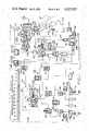
- FIG. 1is a schematic representation of the preferred embodiment of the ventilator system of the present invention
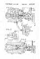
- FIG. 2is a schematic cross-sectional view of the pilot pressure control valve and exhalation valve of the preferred embodiment of the ventilator system of the present invention
- FIG. 3is a plan view taken on lines 3,3 of FIG. 2, and
- FIG. 4is a cross-sectional view of the flow rate control subsystem of the present invention.
- FIG. 1a preferred embodiment of the artificial ventilator system 10 of the present invention is disclosed.
- the preferred embodiment of the ventilator system or ventilator 10 of the present inventionis best described by following the flow path of air, or air oxygen mixtures, through the several components of the ventilator system 10 to a patient 12, and by following the path of the exhalation gases from the patient 12 to the ambient environment.
- An air inlet filter 14 and an oxygen inlet filter 16are shown schematically in the lower left corner of FIG. 1.
- the air filter 14 and the oxygen filter 16receive a pressurized supply of air and oxygen, respectively.
- Air and oxygen which flow through the respective filters 14 and 16enter, through check valves 18 and 20, into an air regulator 22 and an oxygen relay 24, respectively.
- the air and oxygen filters 14 and 16prevent contamination of the ventilator system 10 by aerosols and particulates which may be present in the gases.
- the check valves 18 and 20prevent cross-contamination of the air and oxygen sources.
- Electric pressure switches 26 and 28 and pressure gauges 30 and 32are interposed on the respective lines between the air filter 14 and air regulator 22, and the oxygen filter 16 and the oxygen relay 24.
- the pressure gauge 30measures the actual pressure of air entering the air regulator 22, and pressure gauge 32 measures the actual pressure of oxygen which enters the oxygen relay 24.
- the pressure gauges 30 and 32are preferably mounted on the exterior of the ventilator system 10, so that they can be readily observed by hospital personnel (not shown). Generally speaking, items shown outside of the broken line square box 33 on FIG. 1 are disposed on the exterior of the physical device which embodies the ventilator system 10.
- Each of the pressure switches 26 and 28provides an electric output signal schematically shown on FIG. 1 as 34 and 36, respectively, to the microcomputer controller 38 of the ventilator system 10, to indicate whether or not there is sufficient input pressure of the respective air and oxygen gas. More particularly, in the herein described preferred embodiment the pressure switches 26 and 28 are of the single pole, single throw type, and are preferably calibrated to close when the pressure falls below approximately 28 ⁇ 0.5 pounds per square inch gauge (psig) pressure. When the switches 26 and 28 are open, (as they are during normal operation of the ventilator 10) they send the input signals 34 to 36 to the microcomputer controller 38. When either of the pressure switches is closed because of lack of sufficient pressure on the respective line, the switch sends a signal 34 or 36 directly to a cross-over solenoid valve 40.
- psigpounds per square inch gauge
- the cross-over solenoid valve 40is disposed between the lines leading from the check valves 18 and 20 to the air regulator 22 and oxygen relay 24, respectively.
- the cross-over solenoid 40 valvefunctions in the following manner: During normal operation of the ventilator system 10, the cross-over solenoid valve 40 is closed. When either the air or oxygen supply is interrupted, then the input 34 or 36 of the respective pressure switch 26 or 28 opens the cross-over solenoid valve 40. This permits air or oxygen, as applicable, to enter the air regulator 22, or oxygen relay 24, as applicable.
- the ventilator system 10is able to function with an open cross-over solenoid valve 40 with either air or oxygen supply, although the oxygen concentration level in the respiratory gas delivered to the patient 12 may be compromised.
- the above-mentioned filter, pressure switch, pressure gauge, regulator and solenoid valve components of the ventilator system 10are substantially standard components of state-of-the-art ventilators, and require no detailed structural description.
- the inlet filters 14 and 16are capable of operating in the temperature range of -31 F. to +104 F., have a minimum of 98.5% retention of 0.4 micron sized (or larger) particles, or of 1 micron or larger droplets.
- the range of the pressure gauges 30 and 32is preferably approximately 0 to 100 psig.
- the input pressure of the air and oxygen gases to the respective filters 14 and 16is preferably in the 30 to 100 psig range, since at least 28 ⁇ 0.5 psig is required to keep the system 10 of the preferred embodiment operational.
- the air regulator 22also a substantially standard, state-of-the-art component of the system 10, is a precision instrument which is capable of outputting a substantially constant pressure of air in a wide flow range, preferably in the range of approximately 0 to 80 standard liters per minute (0 to 80 SLPM).
- the air regulator 22is calibrated and set to provide an output of air at 18.2 ⁇ 0.1 psig.
- the oxygen relay 24, also a substantially standard, state-of-the-art component of the system 10,has similar output and pressure regulating characteristics to the air regulator 22. As is shown on the schematic view of FIG. 1, the oxygen relay 24 receives an input pilot pressure from the output of the air regulator 22 to slave the output pressure of the oxygen relay 24 to the air regulator 22. This is important, because in order to have accurate mixing or blending of the air and oxygen gases in the ventilator system 10, the pressures of the two gases must be substantially identical.
- both gasesenter a blender subsystem 44.
- the blender subsystem 44is shown on FIG. 1 enclosed in a box 46 drawn with broken lines.
- the function of the blender subsystem 44is to mix the air and oxygen gases in a ratio which is preselected by the microcomputer controller 38, in accordance with a "respiratory prescription" provided by a physician to suit the individual needs of the patient 12.
- the ratio of air and oxygen in the output of the blender subsystem 44is a preselected control parameter of the ventilator system 10. This ratio is placed into the memory of the microcomputer controller 38 at a front or control panel (not shown) of the system 10.
- the blender subsystem 44 incorporated in the ventilator system 10 of the present inventionmay be state-of-the-art.
- the blender subsystem 44 incorporated in the present inventionincludes a single stage oxygen blending valve 48 which operates on the dual variable orifice principle, as is shown on the schematic view of FIG. 1.
- the pressure balanced air and oxygen linesare connected to separate ports 50 and 52, respectively, of the blending valve 48.
- a stainless steel ball 54 supported by a threaded shaft 56 and a spring loaded pin 57 diametrically opposite the shaft 56moves back and forth between two seats 58 and 60, respectively, to simultaneously control the flow of the two gases.
- the ball 54is moved between the two seats 58 and 60 the flow area of one orifice is increased while that of the opposite one is reduced.
- the total effective flow arearemains constant, regardless of the preselected setting of the blending ratio of the two gases.
- the threaded shaft 56, and therefore the ball 54,are controlled through a flexible coupling 62 by the stepwise rotation of a stepper motor 64.
- the stepper motor 64receives an input 66 from the microcomputer controller 38. This input 66 is responsive, in turn, to the output 68 of optical position sensors 70 which monitor the position of an optical disc 71 mounted to the shaft 56.
- the optical position sensors 70are shown only schematically on FIG. 1.
- the microcomputer controller 38maintains the respiratory gas mixture exiting from the blending valve 48 at the preselected ratio of oxygen and air. As is known, this ratio may vary between approximately 21% O 2 (pure air) to approximately 100% O 2 (pure oxygen gas).
- the respiratory gas mixtureenters into an accumulator 72 of approximately 3.6 liters volume, before it is released from the blender subsystem 44.
- the accumulator 72enables the blender 44 to accomodate sudden demand surges for the respiratory gas.
- the conduit leading from the air regulator 22 to the pilot or control port of the oxygen relay 24is shown to be tapped to lead air at the output pressure of the air regulator 22 (in the herein described preferred embodiment at 18.2 ⁇ 0.1 psig) to and through a drive valve 74.
- the output of the drive valve 74is hereinafter referred to as system air, drive air, or system or drive pressure.
- Another conduitalso tapped from the same source, leads air (at 18.2 ⁇ 0.1 psig) through a safety solenoid valve 76.
- the safety solenoid 76receives its electric control signal 75 from the microcomputer controller 38.
- the control signal 75closes the safety solenoid valve 76.
- the solenoid valve 76is open and allows the pressurized air to pass through into the control or pilot pressure port 78 of the drive valve 74. Therefore, normally, the solenoid valve 76 allows pressurized air to flow through the drive valve 74.
- the drive valve 74has no input and no output regardless of the functioning of the electrical portion of the system 10.
- the drive air output of the drive valve 74is used to drive the pilot pressure control valve of the present invention. Therefore, when there is no pressurized drive air, the artificial ventilation of the system 10 shuts down. In such a case, however, the patient 12 gains access, in a later described manner, to ambient air for spontaneous breathing.
- the blended respiratory gasis led to and through a flow shut-off valve 82.
- the control port 84 of the shut-off valve 82receives the drive air at approximately 18 psig from the drive valve 74. If there is no pilot pressure for the control port 84, the shut-off valve 82 closes. Therefore, if the drive valve 74 has no pressure output, (there is no drive air) the respiratory gas cannot pass through the shut-off valve 82.
- the respiratory gaspasses from the shut-off valve 82 to a flow rate control subsystem 86 of the ventilator 10 of the present invention.
- the hereinafter described structure of the flow rate control subsystem 86is novel.
- the flow rate control subsystem 86is enclosed on FIG. 1 in a box 87 drawn with broken lines. A portion of this subsystem is also shown on the cross-sectional view of FIG. 4. It includes a valve body 88 and a ball valve 90 which interfaces with a valve seat 92. Respiratory gas enters, at approximately 10 to 18 psig pressure, an inlet port 94 of the valve body 88 from the shut-off valve 82. The respiratory gas then passes through the valve formed by the ball 90 and the valve seat 92 and exits from the body 88 through the outlet port 96.
- the position of the ball valve 90 relative to the valve seat 92is controlled by a rod 98 which is mounted in slider bearings 100.
- the rod 98has a cam follower bearing 102 at its end remote from the ball 90.
- the cam follower bearing 102interfaces with an asymmetrical cam 104 mounted to a shaft 106 of a second stepper motor 108. Because the gap between the ball 90 and the valve seat 92 is relatively small even in the fully open position of the valve, the pressure of the respiratory gas drops from approximately 10 to 18 psig to approximately 0 to 2 psig by passing through the valve body 88. Consequently, the pressure on the "high" pressure side of the body 88 presses the cam follower 102 against the asymmetrical cam 104, and no spring or like member is necessary to cause the cam follower 102 to accurately follow the cam 104.
- the second stepper motor 108is controlled by an electric input signal 110 of the microcomputer controller 38.
- the stepper motor 108has 189 steps of rotation which translate to 0.052 inch travel of the control rod 98.
- the stepper motor 108controls the flow rate of respiratory gas through the valve body 88.
- the maximum open and fully closed positions of the valve in the body 88, which correspond to the 189 steps (less than one full rotation) of the stepper motor 108are detected by optical sensors 112.
- the optical sensors 112have light beams (not shown) which are interrupted only in the zero and full flow positions of the valve.
- optical sensors 112 incorporated in the flow control subsystem 86are very similar to the optical sensors incorporated in the pilot pressure control valve of the ventilator 10 of the present invention. Further description of the optical sensors 112 is provided in this specification in connection with the pilot pressure control valve. It is sufficient to note for the purpose of describing the flow control subsystem 86 that an output 114 of the optical sensors 112 provides a reference point to the microcomputer controller 38 to establish and check the two respective extreme positions of the second stepper motor 108.
- the respiratory gasis shown to flow from the outlet port 96 of the valve body 88 to a flow conditioner 116.
- the flow conditioner 116is a state-of-the-art device which minimizes sonic noise and turbulence before the flow enters a flow transducer 118.
- the flow transducer 118is preferably of the type described in U.S. Pat. No. 3,680,375, the specification of which is incorporated herein by reference.
- the flow transducer 118senses the instantaneous flow rate of the respiratory gas, and sends to the microcomputer controller 38 an electronic signal 120 indicative of the sensed flow rate.
- the microcomputer controller 38has stored in its memory, a predetermined flow rate-versus-time function. This function is used to provide a flow rate reference value when the ventilator is delivering a controlled breath, either at preselected time intervals, or in response to a proximal pressure drop indicative of a breathing attempt by the patient.
- a flow rate algorithm stored in the microcomputer's memoryprovides a flow rate reference value which is a function of the patient's instantaneous demand, as measured by changes in the proximal pressure.
- the microcomputer controller 38compares the signal 120 to a flow rate reference value which is required by the stored flow rate-versus-time function, or by the flow rate algorithm, and generates the control signal 110 which is responsive to the difference between the two values.
- the control signal 110is sent to the second stepper motor 108 to control its position, and, if necessary, to adjust the flow rate to match the required value.
- a conduitis shown to lead from the output of the shut-off valve 82 to a purge/bleed valve 121, in parallel with the conduit leading to the flow control subsystem 86.
- the purge/bleed valve 121thus receives respiratory gas at approximately 10 to 18 psig.
- the purge/bleed valve 121which is of substantially standard, state-of-the-art construction, includes a throat 122, a diffuser 124, and two outlets, outlet 126 and orifice 128. In the herein described preferred embodiment the purge/bleed valve 121 is designed to permit an outflow of approximately 2 liters per minute (2 lpm) of respiratory gas through the outlet 126 to the ambient.
- This outflowoccurs through an overboard exhaust outlet 130, which may simply be a tube (not shown specifically) discharging to the environment on the exterior of the ventilator device.
- the orifice 128 of the purge/bleed valve 121provides, in the herein described preferred embodiment an average flow of approximately 0.13 lpm toward the patient 12.
- bias flowIn addition to the continuous flow of respiratory gas through the purge/bleed valve 121, there is a base line (bias) flow of approximately 5 lpm of the gas through the flow control subsystem 86. As will be readily understood from the ensuing description, the bias flow, when not inhaled by the patient 12, is allowed to escape to the environment during the exhalation cycle of the patient.
- the continuous flow of respiratory gas through the purge/bleed valve 121 and the bias flow through the flow control subsystem 86is desirable, because the blender subsystem 44 is unable to blend with sufficient accuracy when the flow is very small.
- the continuous flowpermits the blender 44 to operate at sufficiently high flow rates to assure adequate blending accuracy.
- the small (approximately 0.13 lpm or smaller) flow from the purge/bleed valve 121 toward the patient 12keeps the proximal airway line 129 of the system 10 free of liquids and other material which may originate from the patient 12.
- the respiratory gasis shown on FIG. 1 to enter from the flow transducer 118 into a safety valve subsystem 132.
- the safety valve 132has a control or pilot pressure port 134 which receives drive air from the drive valve 74.
- pilot pressure port 134When there is no input of pilot pressure to the pilot port 134, the safety valve 132 is open through a first outlet port 136 to the overboard exhaust outlet 130, that is to the ambient environment.
- the safety valve 132is closed to the ambient and the respiratory gas flows through a second outlet port 138 of the safety valve 132 toward the patient 12.
- a one-way check valve 140is disposed in the path of the respiratory gas in the safety valve 132 to prevent flow of gas in the opposite direction.
- the respiratory gasflows from the safety valve subsystem 132 through an optional state-of-the-art bacterial filter 142 and a state-of-the-art humidifier 144.
- a temperature sensor 146is incorporated in the safety valve 132 in the path of the respiratory gas to provide an input signal 148 to the microcomputer controller 38.
- the temperature sensor 146is important because the microcomputer controller 38 needs and uses its signal 148 to calculate the volume of gas delivered to the patient 12 under the medically accepted "body temperature, pressure, saturated” conditions.
- a pressure transducer 150is operatively connected to the safety valve 132 to continuously monitor the pressure therein, and to provide an input signal 152 indicative of the pressure to the microcomputer controller 38.
- the pressure which is present in the safety valve 132is commonly termed "machine pressure".
- the machine pressureis an important parameter of the ventilation process in that it is normally only slightly higher than the proximal pressure of the patient 12. Therefore, the pressure transducer 150 functions as a back-up and check on the proximal pressure transducer which is described below.
- the safety valve subsystem 132should be readily apparent from the foregoing description, and inspection of the drawings.
- the safety valve 132opens to provide a conduit through the first outlet port 136 to the ambient environment. Under these conditions the patient 12 is able to inhale ambient air through the safety valve 132.
- the one-way check valve 140prevents the patient 12 from exhaling through the safety valve 132. As it is described below, the patient 12 can always exhale through the exhalation valve of the ventilator 10 of the present invention, even in the event of electrical power or other system failure.
- the one-way check valve 140also prevents water vapors from entering upstream into the system from a humidifier which is described below.
- the respiratory gasflows from the humidifier 144 to a Y-tube 154 which is connected to inhalation tubes (not shown) of the patient 12, and to the exhalation valve.
- a bacterial filter 156is interposed on the conduit between the purge/bleed valve 121 and the Y-tube 150.
- proximal pressureThe pressure which prevails in the Y-tube 154, or its vicinity, is commonly known in the art as "proximal pressure".
- proximal pressureis a very important parameter of the ventilator 10, and of the artificial ventilation process.
- the proximal pressureis continuously monitored, and it is displayed on a pressure gauge 158.
- the proximal pressureis also monitored by a pressure transducer 160 which provides to the microcomputer controller 38 an input signal 162 indicative of the proximal pressure.
- the exhalation valve 164which is connected to the Y-tube 154 (patient circuit) with a conduit is shown in the upper right of FIG. 1 and, in more structural detail, in FIG. 2.
- the exhalation valve 164may be constructed in accordance with the state of the art, as is shown on the drawing Figures.
- An exhalation valvewhich is particularly well adapted for use in the ventilator system 10 of the present invention, is described in detail in a co-pending application filed on the same date with the present application, assigned to the same assignee and titled Low-Noise Exhalation Valve For Medical Ventilator. The specification of this co-pending application is expressly incorporated herein by reference.
- the exhalation valve 164operates as a piloted relief valve. Thus, it has an inlet port 166, an outlet port 168 leading to a condensation trap 170, and a second outlet port 172 to a temperature controlled chamber 174.
- the external flow transducer 176provides to the microcomputer controller 38 an input signal 178 indicative of the flow rate of gases leaving the system 10.
- the temperature controlled chamber 174is necessary, because, as is known in the art, the temperature of the flow transducer 176 must be elevated in order to prevent condensation.
- a balloon valveincluding a balloon 180 and a valve seat 182, is incorporated in the exhalation valve 164.
- the balloon 180is controlled by a pilot pressure, which is the internal pressure in the balloon 180.
- the pilot pressureexceeds the pressure in the exhalation valve 164, the balloon 180 inflates and seats against the valve seat 182 to block the flow of gas through the exhalation valve 164.
- an aluminum or like metal plate 184is molded integrally with the balloon 180 to seat against the valve seat 182 and to add rigidity and stability to the functioning of the valve.
- the pilot pressure governing the balloon 180controls the proximal pressure in the system in the sense that the proximal pressure cannot exceed the pilot pressure of the balloon 180.
- the structure of the pilot pressure control valve which controls the pilot pressure of the balloon 180is a novel aspect of the present invention. Similarly, the manner in which the pilot pressure control valve interfaces and functions in the entire system 10 is considered novel.
- the pressure control subsystem 80is shown to include a valve body 186, an inlet port 188, a first outlet port 190, a second outlet port 192 and an internal conduit or reservoir 194 for air.
- the inlet port 188receives drive air or system air (at approximately 18 psig) from the drive valve 74.
- the drive airflows from the inlet port 188 through a jet 196, a throat 197 and a diffuser duct 198.
- a chamber 200 surrounding the jet 196is connected by another duct 202 to the internal conduit or reservoir 194.
- the gas around the jet peripherymay be entrained with the jet flow causing a greater combined flow, or be flowing counter to the jet flow causing a lesser net flow.
- the air flowcontinues from the diffuser duct 198 through a valve, including a valve seat 204 and a ball 206, to the internal conduit 194.
- the first outlet port 190leads from the internal conduit 194 to the ambient.
- the second outlet port 192is disposed in the air flow between the jet 196 on the one hand, and the valve seat 204 and ball 206 on the other hand.
- the position of the ball 206 relative to the valve seat 204is regulated by a control rod 208 which is mounted in the valve body 186 for longitudinal motion relative to the ball 206 and the valve seat 204.
- the control rod 208has a cam follower bearing 210 at its end which is remote from the ball 206.
- the cam follower 210follows an asymmetrical cam 212 mounted to the rotatable shaft 214 of a third stepper motor 216.
- the cam follower 210is urged against the cam 212 by a spring 218.
- the static pressure in the diffuser duct 198 and therefore in the second, static outlet port 192depends on the flow rate, and therefore on the position of the ball 206 relative to the valve seat 204.
- the static pressure in the outlet port 192is the pilot pressure for the balloon 180 of the exhalation valve 164.
- the jet orificeis 0.016 inch in diameter.
- the static port pressure-versus-ball position curveis not linear. In fact, it is possible for a negative (less than ambient) pressure to exist in the static port 192 when the valve is wide open (the ball 206 is far removed from the valve seat 204).
- An accurate pilot pressure-versus-ball position calibration curveis obtained within the practice of the present invention. This curve may be utilized in connection with the function of the microcomputer controller 38 which governs the pilot pressure control valve. In the operating range of the preferred embodiment, the pressure in the static port 192 varies between approximately zero to approximately 150 centimeters of water (cmH 2 O).
- the asymmetrical cam 212is constructed in such a manner that its configuration compensates for the non-linearity of the pilot (static port) pressure-versus-ball position relationship.
- the configuration of the cam 212results in a substantially linear pilot pressure-versus-stepper motor step position relationship. Further adjustments to obtain a substantially linear and well defined pilot pressure-versus-stepper motor step position relationship can be made by moving (threading) the entire jet-throat assembly in or out until a desired zero point is achieved, and by adjusting the size of the orifice upstream of the jet 196.
- the third stepper motor 216is controlled by the output 220 of the microcomputer controller 38, to rotate the shaft 214, to linearly position the control rod 208 and the ball 206 into the position which provides the desired pressure in the static port 192.
- the output 220 of the microcomputer controller 38is responsive to the input signal 162 received by the microcomputer controller 38 from the proximal pressure transducer 160.
- the microcomputer controller 38has stored in its memory, a predetermined pressure-versus-time function. This function is used to provide a pressure reference value when the ventilator is delivering a controlled breath, either at preselected time intervals, or in response to a proximal pressure drop indicative of a breathing attempt by the patient.
- a pressure algorithm stored in the microcomputer's memoryprovides a pressure reference value which is a function of the patient's instantaneous demand, as measured by changes in the proximal pressure.
- the stored pressure functionmay be proximal pressure-versus-time function, or pilot pressure-versus-time function, or both.
- proximal pressuremay be below the pilot pressure.
- the pilot pressure-versus-time functionmay be relatively simple. For example, in machine controlled volume ventilation the pilot pressure may simply alternate, for predetermined periods of time, between zero and a constant pressure value. For machine controlled volume ventilation with positive end expiratory pressure (PEEP), the pilot pressure may alternate between a higher and lower pressure value, the lower one being the PEEP pressure value.
- PEEPpositive end expiratory pressure
- the preselected pilot pressure-versus-time functionis fundamentally different for machine controlled breathing than it is for assisted or spontaneous breathing.
- the microcomputer controller 38compares the proximal pressure value derived from the input 162 of the pressure transducer 160 to the pilot pressure reference value required by the stored pressure-versus-time function, or by the pressure algorithm. The microcomputer controller 38 then generates an output signal 220 which is indicative of this difference, and which is used to control the third stepper motor 216.
- the optical sensors 224 and 226send to the microcomputer controller 38 a signal 228 or 230, respectively, to indicate that the shaft 214 has reached a respective extreme position.
- the signal 226 or 228is then used by the microcomputer controller 38 to calculate the number of steps necessary to place the stepper motor 216 in the next desired position.
- microcomputer controller 38 of the ventilator system of the present inventionneed not be described here in detail.
- the hereinabove described functions of the microcomputer controller 38may be accomplished, under the governance of appropriate software, by a general purpose computer or microprocessor and associated state-of-the-art electronics.
- the softwarecan be generated by those skilled in the art on the basis of the above description of the functional aspects of the present invention.
Landscapes
- Health & Medical Sciences (AREA)
- Pulmonology (AREA)
- Emergency Medicine (AREA)
- Engineering & Computer Science (AREA)
- Anesthesiology (AREA)
- Biomedical Technology (AREA)
- Heart & Thoracic Surgery (AREA)
- Hematology (AREA)
- Life Sciences & Earth Sciences (AREA)
- Animal Behavior & Ethology (AREA)
- General Health & Medical Sciences (AREA)
- Public Health (AREA)
- Veterinary Medicine (AREA)
- Respiratory Apparatuses And Protective Means (AREA)
Abstract
Description
Claims (34)
Priority Applications (8)
| Application Number | Priority Date | Filing Date | Title |
|---|---|---|---|
| US06/667,115US4527557A (en) | 1984-11-01 | 1984-11-01 | Medical ventilator system |
| CA000485983ACA1237357A (en) | 1984-11-01 | 1985-06-28 | Medical ventilator system |
| EP85903575AEP0200737B1 (en) | 1984-11-01 | 1985-07-01 | Medical ventilator system |
| EP89201993AEP0347015B1 (en) | 1984-11-01 | 1985-07-01 | Medical ventilator system |
| DE8989201993TDE3586895T2 (en) | 1984-11-01 | 1985-07-01 | VENTILATION SYSTEM. |
| PCT/US1985/001239WO1986002563A1 (en) | 1984-11-01 | 1985-07-01 | Medical ventilator system |
| JP60503107AJPS62501051A (en) | 1984-11-01 | 1985-07-01 | medical breathing apparatus |
| DE8585903575TDE3584161D1 (en) | 1984-11-01 | 1985-07-01 | ARTIFICIAL VENTILATION SYSTEM. |
Applications Claiming Priority (1)
| Application Number | Priority Date | Filing Date | Title |
|---|---|---|---|
| US06/667,115US4527557A (en) | 1984-11-01 | 1984-11-01 | Medical ventilator system |
Publications (1)
| Publication Number | Publication Date |
|---|---|
| US4527557Atrue US4527557A (en) | 1985-07-09 |
Family
ID=24676853
Family Applications (1)
| Application Number | Title | Priority Date | Filing Date |
|---|---|---|---|
| US06/667,115Expired - LifetimeUS4527557A (en) | 1984-11-01 | 1984-11-01 | Medical ventilator system |
Country Status (6)
| Country | Link |
|---|---|
| US (1) | US4527557A (en) |
| EP (2) | EP0347015B1 (en) |
| JP (1) | JPS62501051A (en) |
| CA (1) | CA1237357A (en) |
| DE (2) | DE3586895T2 (en) |
| WO (1) | WO1986002563A1 (en) |
Cited By (118)
| Publication number | Priority date | Publication date | Assignee | Title |
|---|---|---|---|---|
| US4611591A (en)* | 1984-07-10 | 1986-09-16 | Sharp Kabushiki Kaisha | Expiration valve control for automatic respirator |
| US4776333A (en)* | 1984-02-02 | 1988-10-11 | Sharp Kabushiki Kaisha | Ventilator with variable flow pattern |
| EP0266963A3 (en)* | 1986-11-04 | 1988-11-23 | Bird Products Corporation | Ventilator exhalation valve |
| US4838257A (en)* | 1987-07-17 | 1989-06-13 | Hatch Guy M | Ventilator |
| US4941469A (en)* | 1987-11-12 | 1990-07-17 | Carmeli Adahan | Portable ventilator apparatus |
| WO1990014121A1 (en)* | 1989-05-19 | 1990-11-29 | Puritan-Bennett Corporation | Inspiratory airway pressure system |
| US5072729A (en)* | 1986-11-04 | 1991-12-17 | Bird Products Corporation | Ventilator exhalation valve |
| US5092326A (en)* | 1987-11-19 | 1992-03-03 | Winn Bryan D | Apparatus and method for a ventilator system |
| US5134995A (en)* | 1989-05-19 | 1992-08-04 | Puritan-Bennett Corporation | Inspiratory airway pressure system with admittance determining apparatus and method |
| US5161525A (en)* | 1990-05-11 | 1992-11-10 | Puritan-Bennett Corporation | System and method for flow triggering of pressure supported ventilation |
| EP0548624A1 (en)* | 1991-12-09 | 1993-06-30 | BOC Health Care, Inc. | Medical ventilator |
| US5331995A (en)* | 1992-07-17 | 1994-07-26 | Bear Medical Systems, Inc. | Flow control system for medical ventilator |
| US5339807A (en)* | 1992-09-22 | 1994-08-23 | Puritan-Bennett Corporation | Exhalation valve stabilizing apparatus |
| EP0615764A1 (en)* | 1993-03-16 | 1994-09-21 | Puritan-Bennett Corporation | System and method for closed loop inspiratory pressure control in a ventilator |
| US5390666A (en)* | 1990-05-11 | 1995-02-21 | Puritan-Bennett Corporation | System and method for flow triggering of breath supported ventilation |
| US5429123A (en)* | 1993-12-15 | 1995-07-04 | Temple University - Of The Commonwealth System Of Higher Education | Process control and apparatus for ventilation procedures with helium and oxygen mixtures |
| US5433193A (en)* | 1989-09-22 | 1995-07-18 | Respironics Inc. | Breathing gas delivery method and apparatus |
| US5438980A (en)* | 1993-01-12 | 1995-08-08 | Puritan-Bennett Corporation | Inhalation/exhalation respiratory phase detection circuit |
| US5474062A (en)* | 1987-11-04 | 1995-12-12 | Bird Products Corporation | Medical ventilator |
| US5494028A (en)* | 1986-11-04 | 1996-02-27 | Bird Products Corporation | Medical ventilator |
| US5540220A (en)* | 1994-12-08 | 1996-07-30 | Bear Medical Systems, Inc. | Pressure-limited, time-cycled pulmonary ventilation with volume-cycle override |
| US5594666A (en)* | 1993-12-20 | 1997-01-14 | Mks Japan, Inc. | Mass flow control system |
| US5632269A (en)* | 1989-09-22 | 1997-05-27 | Respironics Inc. | Breathing gas delivery method and apparatus |
| US5664563A (en)* | 1994-12-09 | 1997-09-09 | Cardiopulmonary Corporation | Pneumatic system |
| US5694926A (en)* | 1994-10-14 | 1997-12-09 | Bird Products Corporation | Portable drag compressor powered mechanical ventilator |
| US5813399A (en)* | 1993-03-16 | 1998-09-29 | Puritan Bennett Corporation | System and method for closed loop airway pressure control during the inspiratory cycle of a breath in a patient ventilator using the exhalation valve as a microcomputer-controlled relief valve |
| US5918597A (en)* | 1998-01-15 | 1999-07-06 | Nellcor Puritan Bennett | Peep control in a piston ventilator |
| FR2784587A1 (en)* | 1998-10-19 | 2000-04-21 | Saime Sarl | Patient respiratory assistance system has exhalation valve fed from controlled air pressure source fitted with regulated discharge valve |
| US6073630A (en)* | 1994-02-28 | 2000-06-13 | Flight Medical Ltd. | Exhalation valve assembly |
| US6076523A (en)* | 1998-01-15 | 2000-06-20 | Nellcor Puritan Bennett | Oxygen blending in a piston ventilator |
| US6119723A (en)* | 1997-02-14 | 2000-09-19 | Resmed Limited, | Apparatus for varying the flow area of a conduit |
| US6135967A (en)* | 1999-04-26 | 2000-10-24 | Fiorenza; Anthony Joseph | Respiratory ventilator with automatic flow calibration |
| WO2000064521A1 (en) | 1999-04-27 | 2000-11-02 | Loma Linda University Medical Center | Device and method for the administration of oxygen |
| US6240919B1 (en) | 1999-06-07 | 2001-06-05 | Macdonald John J. | Method for providing respiratory airway support pressure |
| US6253764B1 (en) | 1996-05-08 | 2001-07-03 | Resmed, Ltd. | Control of delivery pressure in CPAP treatment or assisted respiration |
| EP1118347A1 (en)* | 2000-01-21 | 2001-07-25 | Taema | Anaesthesia breathing device with controlled discharge valve |
| US6532957B2 (en) | 1996-09-23 | 2003-03-18 | Resmed Limited | Assisted ventilation to match patient respiratory need |
| US6581601B2 (en)* | 1999-06-18 | 2003-06-24 | Saeed Ziaee | Nasal mask with balloon exhalation valve |
| US20040200476A1 (en)* | 2003-01-29 | 2004-10-14 | Bamford Owen S. | Method for reducing the work of breathing |
| US20040245658A1 (en)* | 2000-12-08 | 2004-12-09 | Niland William F. | Apparatus and method for delivering water vapor to a gas |
| US20050034721A1 (en)* | 2003-08-11 | 2005-02-17 | Lutz Freitag | Tracheal catheter and prosthesis and method of respiratory support of a patient |
| US20050039740A1 (en)* | 2003-05-13 | 2005-02-24 | Ino Therapeutics Gmbh | Method and system for the controlled admixing of a gas or a gas mixture to a gas (mixture) flow |
| US20060278227A1 (en)* | 2005-06-08 | 2006-12-14 | Imi Norgren, Inc. | Ventilator system |
| WO2006130369A3 (en)* | 2005-05-31 | 2007-11-22 | Ventendo Products Corp Inc | Method and system for non-invasive ventilatory support |
| US20080029088A1 (en)* | 2006-05-18 | 2008-02-07 | Breathe Technologies, Inc. | Tracheostoma spacer, tracheotomy method, and device for inserting a tracheostoma spacer |
| US20080264419A1 (en)* | 2007-04-26 | 2008-10-30 | Joseph Lomask | Integrated ventilator with calibration |
| US20080289631A1 (en)* | 1999-12-10 | 2008-11-27 | Gary Schroeder | Apparatus and method for respiratory tract therapy |
| WO2008147229A1 (en)* | 2007-05-30 | 2008-12-04 | Gilbert Jacobus Kuypers | Improvements to electrically operable resuscitators |
| US7533670B1 (en) | 2005-09-20 | 2009-05-19 | Breathe Technologies, Inc. | Systems, methods and apparatus for respiratory support of a patient |
| US7588033B2 (en) | 2003-06-18 | 2009-09-15 | Breathe Technologies, Inc. | Methods, systems and devices for improving ventilation in a lung area |
| US20100071693A1 (en)* | 2008-08-22 | 2010-03-25 | Breathe Technologies | Methods and devices for providing mechanical ventilation with an open airway interface |
| US20100282257A1 (en)* | 2006-01-24 | 2010-11-11 | Devx Tech Ip Limited [Nz/Nz] | Fluid Mixing Apparatus With an Improved Mixer |
| EP1986723A4 (en)* | 2006-02-21 | 2011-11-23 | Carefusion 207 Inc | HARDWARE CONFIGURATION FOR PRESSURE CONTROL DEVICE |
| USD653749S1 (en) | 2010-04-27 | 2012-02-07 | Nellcor Puritan Bennett Llc | Exhalation module filter body |
| USD655405S1 (en) | 2010-04-27 | 2012-03-06 | Nellcor Puritan Bennett Llc | Filter and valve body for an exhalation module |
| USD655809S1 (en) | 2010-04-27 | 2012-03-13 | Nellcor Puritan Bennett Llc | Valve body with integral flow meter for an exhalation module |
| US8136527B2 (en) | 2003-08-18 | 2012-03-20 | Breathe Technologies, Inc. | Method and device for non-invasive ventilation with nasal interface |
| CN102500020A (en)* | 2011-09-28 | 2012-06-20 | 于邦仲 | Pilot-operated type control air channel system of breathing machine |
| US8381729B2 (en) | 2003-06-18 | 2013-02-26 | Breathe Technologies, Inc. | Methods and devices for minimally invasive respiratory support |
| US8434479B2 (en) | 2009-02-27 | 2013-05-07 | Covidien Lp | Flow rate compensation for transient thermal response of hot-wire anemometers |
| US8439037B2 (en) | 2009-12-01 | 2013-05-14 | Covidien Lp | Exhalation valve assembly with integrated filter and flow sensor |
| US8439036B2 (en) | 2009-12-01 | 2013-05-14 | Covidien Lp | Exhalation valve assembly with integral flow sensor |
| US8457706B2 (en) | 2008-05-16 | 2013-06-04 | Covidien Lp | Estimation of a physiological parameter using a neural network |
| US8469030B2 (en) | 2009-12-01 | 2013-06-25 | Covidien Lp | Exhalation valve assembly with selectable contagious/non-contagious latch |
| US8469031B2 (en) | 2009-12-01 | 2013-06-25 | Covidien Lp | Exhalation valve assembly with integrated filter |
| CN103182142A (en)* | 2011-12-30 | 2013-07-03 | 北京谊安医疗系统股份有限公司 | Oxygen mixing valve |
| US20130206144A1 (en)* | 2010-10-26 | 2013-08-15 | Koninklijke Philips Electronics N.V. | Pressure line purging system for a mechanical ventilator |
| USD692556S1 (en) | 2013-03-08 | 2013-10-29 | Covidien Lp | Expiratory filter body of an exhalation module |
| US8567399B2 (en) | 2007-09-26 | 2013-10-29 | Breathe Technologies, Inc. | Methods and devices for providing inspiratory and expiratory flow relief during ventilation therapy |
| USD693001S1 (en) | 2013-03-08 | 2013-11-05 | Covidien Lp | Neonate expiratory filter assembly of an exhalation module |
| USD701601S1 (en) | 2013-03-08 | 2014-03-25 | Covidien Lp | Condensate vial of an exhalation module |
| CN103751894A (en)* | 2013-12-31 | 2014-04-30 | 沈阳理工大学 | Digital control medical respirator |
| US8770193B2 (en) | 2008-04-18 | 2014-07-08 | Breathe Technologies, Inc. | Methods and devices for sensing respiration and controlling ventilator functions |
| US8776793B2 (en) | 2008-04-18 | 2014-07-15 | Breathe Technologies, Inc. | Methods and devices for sensing respiration and controlling ventilator functions |
| US8776792B2 (en) | 2011-04-29 | 2014-07-15 | Covidien Lp | Methods and systems for volume-targeted minimum pressure-control ventilation |
| US8800557B2 (en) | 2003-07-29 | 2014-08-12 | Covidien Lp | System and process for supplying respiratory gas under pressure or volumetrically |
| US20140283834A1 (en)* | 2013-03-22 | 2014-09-25 | Breathe Technologies, Inc. | Portable ventilator secretion management system |
| US8844526B2 (en) | 2012-03-30 | 2014-09-30 | Covidien Lp | Methods and systems for triggering with unknown base flow |
| US8925545B2 (en) | 2004-02-04 | 2015-01-06 | Breathe Technologies, Inc. | Methods and devices for treating sleep apnea |
| US8939152B2 (en) | 2010-09-30 | 2015-01-27 | Breathe Technologies, Inc. | Methods, systems and devices for humidifying a respiratory tract |
| US9022031B2 (en) | 2012-01-31 | 2015-05-05 | Covidien Lp | Using estimated carinal pressure for feedback control of carinal pressure during ventilation |
| USD731065S1 (en) | 2013-03-08 | 2015-06-02 | Covidien Lp | EVQ pressure sensor filter of an exhalation module |
| USD731048S1 (en) | 2013-03-08 | 2015-06-02 | Covidien Lp | EVQ diaphragm of an exhalation module |
| USD731049S1 (en) | 2013-03-05 | 2015-06-02 | Covidien Lp | EVQ housing of an exhalation module |
| USD736905S1 (en) | 2013-03-08 | 2015-08-18 | Covidien Lp | Exhalation module EVQ housing |
| US9132250B2 (en) | 2009-09-03 | 2015-09-15 | Breathe Technologies, Inc. | Methods, systems and devices for non-invasive ventilation including a non-sealing ventilation interface with an entrainment port and/or pressure feature |
| US9144658B2 (en) | 2012-04-30 | 2015-09-29 | Covidien Lp | Minimizing imposed expiratory resistance of mechanical ventilator by optimizing exhalation valve control |
| US9180270B2 (en) | 2009-04-02 | 2015-11-10 | Breathe Technologies, Inc. | Methods, systems and devices for non-invasive open ventilation with gas delivery nozzles within an outer tube |
| USD744095S1 (en) | 2013-03-08 | 2015-11-24 | Covidien Lp | Exhalation module EVQ internal flow sensor |
| US9358355B2 (en) | 2013-03-11 | 2016-06-07 | Covidien Lp | Methods and systems for managing a patient move |
| US9364624B2 (en) | 2011-12-07 | 2016-06-14 | Covidien Lp | Methods and systems for adaptive base flow |
| US9375542B2 (en) | 2012-11-08 | 2016-06-28 | Covidien Lp | Systems and methods for monitoring, managing, and/or preventing fatigue during ventilation |
| US9492629B2 (en) | 2013-02-14 | 2016-11-15 | Covidien Lp | Methods and systems for ventilation with unknown exhalation flow and exhalation pressure |
| US9498589B2 (en) | 2011-12-31 | 2016-11-22 | Covidien Lp | Methods and systems for adaptive base flow and leak compensation |
| USD775345S1 (en) | 2015-04-10 | 2016-12-27 | Covidien Lp | Ventilator console |
| US9629971B2 (en) | 2011-04-29 | 2017-04-25 | Covidien Lp | Methods and systems for exhalation control and trajectory optimization |
| US9649458B2 (en) | 2008-09-30 | 2017-05-16 | Covidien Lp | Breathing assistance system with multiple pressure sensors |
| EP2289583A3 (en)* | 2003-03-24 | 2017-12-20 | ResMed Paris SAS | Breathing assistance apparatus |
| US9925346B2 (en) | 2015-01-20 | 2018-03-27 | Covidien Lp | Systems and methods for ventilation with unknown exhalation flow |
| US9950135B2 (en) | 2013-03-15 | 2018-04-24 | Covidien Lp | Maintaining an exhalation valve sensor assembly |
| US9956371B2 (en) | 2015-03-24 | 2018-05-01 | Ventec Life Systems, Inc. | Ventilator with integrated cough-assist |
| US9962512B2 (en) | 2009-04-02 | 2018-05-08 | Breathe Technologies, Inc. | Methods, systems and devices for non-invasive ventilation including a non-sealing ventilation interface with a free space nozzle feature |
| US9981096B2 (en) | 2013-03-13 | 2018-05-29 | Covidien Lp | Methods and systems for triggering with unknown inspiratory flow |
| US9993604B2 (en) | 2012-04-27 | 2018-06-12 | Covidien Lp | Methods and systems for an optimized proportional assist ventilation |
| US10058668B2 (en) | 2007-05-18 | 2018-08-28 | Breathe Technologies, Inc. | Methods and devices for sensing respiration and providing ventilation therapy |
| US10099028B2 (en) | 2010-08-16 | 2018-10-16 | Breathe Technologies, Inc. | Methods, systems and devices using LOX to provide ventilatory support |
| US10252020B2 (en) | 2008-10-01 | 2019-04-09 | Breathe Technologies, Inc. | Ventilator with biofeedback monitoring and control for improving patient activity and health |
| US10668239B2 (en) | 2017-11-14 | 2020-06-02 | Covidien Lp | Systems and methods for drive pressure spontaneous ventilation |
| US10773049B2 (en) | 2016-06-21 | 2020-09-15 | Ventec Life Systems, Inc. | Cough-assist systems with humidifier bypass |
| US10792449B2 (en) | 2017-10-03 | 2020-10-06 | Breathe Technologies, Inc. | Patient interface with integrated jet pump |
| US11154672B2 (en) | 2009-09-03 | 2021-10-26 | Breathe Technologies, Inc. | Methods, systems and devices for non-invasive ventilation including a non-sealing ventilation interface with an entrainment port and/or pressure feature |
| WO2021223154A1 (en)* | 2020-05-07 | 2021-11-11 | 雷激 | Ventilator |
| US11191915B2 (en) | 2018-05-13 | 2021-12-07 | Ventec Life Systems, Inc. | Portable medical ventilator system using portable oxygen concentrators |
| US11247015B2 (en) | 2015-03-24 | 2022-02-15 | Ventec Life Systems, Inc. | Ventilator with integrated oxygen production |
| US11517691B2 (en) | 2018-09-07 | 2022-12-06 | Covidien Lp | Methods and systems for high pressure controlled ventilation |
| US11844906B1 (en)* | 2021-04-29 | 2023-12-19 | Selvaanish Selvam | Oxygen-air blender for neonates |
| US11896767B2 (en) | 2020-03-20 | 2024-02-13 | Covidien Lp | Model-driven system integration in medical ventilators |
| US12440634B2 (en) | 2021-12-21 | 2025-10-14 | Ventec Life Systems, Inc. | Ventilator systems with integrated oxygen delivery, and associated devices and methods |
Families Citing this family (8)
| Publication number | Priority date | Publication date | Assignee | Title |
|---|---|---|---|---|
| US5303698A (en)* | 1991-08-27 | 1994-04-19 | The Boc Group, Inc. | Medical ventilator |
| FI92286C (en)* | 1992-02-21 | 1994-10-25 | Instrumentarium Oy | Device for controlling the gas volume supplied to a patient during an inhalation phase |
| EP0667169B1 (en)* | 1994-01-12 | 1999-04-07 | Société d'Applications Industrielles Medicales et Electroniques ( SAIME) | Device for respiratory assistance with limited pressure mode of treating support |
| FR2714837B1 (en)* | 1994-01-12 | 1996-09-06 | Saime | Device for assisting the ventilation of a patient, comprising in particular a volumetric inspiratory assistance mode. |
| US5751606A (en)* | 1996-05-03 | 1998-05-12 | Hk Medical Technologies Incorporated | Automatic valve test apparatus |
| JP2002136598A (en)* | 2000-11-02 | 2002-05-14 | Kawasaki Safety Service Industries Ltd | Expiratory valve device for artificial respirator |
| US20220211968A1 (en)* | 2019-03-13 | 2022-07-07 | Magnamed Tecnologia Medica S/A | Transportable lung ventilator |
| CN112972846B (en)* | 2021-03-04 | 2022-10-04 | 河北北方学院附属第一医院 | Emergency call department is with portable automatic respirator |
Citations (14)
| Publication number | Priority date | Publication date | Assignee | Title |
|---|---|---|---|---|
| US3028860A (en)* | 1957-02-27 | 1962-04-10 | Spirotechnique | Reserve disposal arrangement for breathing apparatus |
| US3903881A (en)* | 1974-04-12 | 1975-09-09 | Bourns Inc | Respirator system and method |
| US4036221A (en)* | 1972-05-01 | 1977-07-19 | Sutter Hospitals Medical Research Foundation | Respirator |
| US4097786A (en)* | 1976-06-16 | 1978-06-27 | E-Systems, Inc. | Limit control apparatus |
| US4204536A (en)* | 1977-06-30 | 1980-05-27 | U.S. Philips Corporation | Respirator |
| US4262689A (en)* | 1978-10-13 | 1981-04-21 | Rodder Jerome A | Respirator valve |
| US4323064A (en)* | 1976-10-26 | 1982-04-06 | Puritan-Bennett Corporation | Volume ventilator |
| US4326513A (en)* | 1979-07-02 | 1982-04-27 | Dragerwerk Ag | Patient data controlled respiration system |
| US4333453A (en)* | 1978-10-13 | 1982-06-08 | Rodder Jerome A | Respirator valve |
| US4336590A (en)* | 1979-05-02 | 1982-06-22 | Intertechnique | Devices for controlling gas flows |
| US4344144A (en)* | 1979-05-02 | 1982-08-10 | Intertechnique | Apparatus for creating gas flow cycles |
| US4345612A (en)* | 1979-06-12 | 1982-08-24 | Citizen Watch Company Limited | Anesthetic gas control apparatus |
| US4401116A (en)* | 1980-12-04 | 1983-08-30 | Bear Medical Systems, Inc. | Gas flow rate control device for medical ventilator |
| US4448192A (en)* | 1982-03-05 | 1984-05-15 | Hewlett Packard Company | Medical ventilator device parametrically controlled for patient ventilation |
Family Cites Families (4)
| Publication number | Priority date | Publication date | Assignee | Title |
|---|---|---|---|---|
| US3820539A (en)* | 1972-10-19 | 1974-06-28 | Veriflo Corp | Ventilator with compliance isolation switch |
| CH568756A5 (en)* | 1973-09-07 | 1975-11-14 | Hoffmann La Roche | |
| USRE29778E (en)* | 1974-06-07 | 1978-09-26 | Bio-Med Devices, Inc. | Pediatric respirator |
| SE418456B (en)* | 1979-06-21 | 1981-06-09 | Engstrom Medical Ab | ventilator |
- 1984
- 1984-11-01USUS06/667,115patent/US4527557A/ennot_activeExpired - Lifetime
- 1985
- 1985-06-28CACA000485983Apatent/CA1237357A/ennot_activeExpired
- 1985-07-01EPEP89201993Apatent/EP0347015B1/ennot_activeExpired - Lifetime
- 1985-07-01WOPCT/US1985/001239patent/WO1986002563A1/enactiveIP Right Grant
- 1985-07-01EPEP85903575Apatent/EP0200737B1/ennot_activeExpired - Lifetime
- 1985-07-01DEDE8989201993Tpatent/DE3586895T2/ennot_activeExpired - Fee Related
- 1985-07-01JPJP60503107Apatent/JPS62501051A/enactiveGranted
- 1985-07-01DEDE8585903575Tpatent/DE3584161D1/ennot_activeExpired - Lifetime
Patent Citations (14)
| Publication number | Priority date | Publication date | Assignee | Title |
|---|---|---|---|---|
| US3028860A (en)* | 1957-02-27 | 1962-04-10 | Spirotechnique | Reserve disposal arrangement for breathing apparatus |
| US4036221A (en)* | 1972-05-01 | 1977-07-19 | Sutter Hospitals Medical Research Foundation | Respirator |
| US3903881A (en)* | 1974-04-12 | 1975-09-09 | Bourns Inc | Respirator system and method |
| US4097786A (en)* | 1976-06-16 | 1978-06-27 | E-Systems, Inc. | Limit control apparatus |
| US4323064A (en)* | 1976-10-26 | 1982-04-06 | Puritan-Bennett Corporation | Volume ventilator |
| US4204536A (en)* | 1977-06-30 | 1980-05-27 | U.S. Philips Corporation | Respirator |
| US4262689A (en)* | 1978-10-13 | 1981-04-21 | Rodder Jerome A | Respirator valve |
| US4333453A (en)* | 1978-10-13 | 1982-06-08 | Rodder Jerome A | Respirator valve |
| US4336590A (en)* | 1979-05-02 | 1982-06-22 | Intertechnique | Devices for controlling gas flows |
| US4344144A (en)* | 1979-05-02 | 1982-08-10 | Intertechnique | Apparatus for creating gas flow cycles |
| US4345612A (en)* | 1979-06-12 | 1982-08-24 | Citizen Watch Company Limited | Anesthetic gas control apparatus |
| US4326513A (en)* | 1979-07-02 | 1982-04-27 | Dragerwerk Ag | Patient data controlled respiration system |
| US4401116A (en)* | 1980-12-04 | 1983-08-30 | Bear Medical Systems, Inc. | Gas flow rate control device for medical ventilator |
| US4448192A (en)* | 1982-03-05 | 1984-05-15 | Hewlett Packard Company | Medical ventilator device parametrically controlled for patient ventilation |
Cited By (212)
| Publication number | Priority date | Publication date | Assignee | Title |
|---|---|---|---|---|
| US4776333A (en)* | 1984-02-02 | 1988-10-11 | Sharp Kabushiki Kaisha | Ventilator with variable flow pattern |
| US4611591A (en)* | 1984-07-10 | 1986-09-16 | Sharp Kabushiki Kaisha | Expiration valve control for automatic respirator |
| EP0266963A3 (en)* | 1986-11-04 | 1988-11-23 | Bird Products Corporation | Ventilator exhalation valve |
| US5072729A (en)* | 1986-11-04 | 1991-12-17 | Bird Products Corporation | Ventilator exhalation valve |
| JP3058881B2 (en) | 1986-11-04 | 2000-07-04 | バード・プロダクツ・コーポレーション | Ventilator delivering multiple substantially identical breaths |
| US5494028A (en)* | 1986-11-04 | 1996-02-27 | Bird Products Corporation | Medical ventilator |
| US4838257A (en)* | 1987-07-17 | 1989-06-13 | Hatch Guy M | Ventilator |
| US5474062A (en)* | 1987-11-04 | 1995-12-12 | Bird Products Corporation | Medical ventilator |
| US4941469A (en)* | 1987-11-12 | 1990-07-17 | Carmeli Adahan | Portable ventilator apparatus |
| US5092326A (en)* | 1987-11-19 | 1992-03-03 | Winn Bryan D | Apparatus and method for a ventilator system |
| WO1990014121A1 (en)* | 1989-05-19 | 1990-11-29 | Puritan-Bennett Corporation | Inspiratory airway pressure system |
| US5134995A (en)* | 1989-05-19 | 1992-08-04 | Puritan-Bennett Corporation | Inspiratory airway pressure system with admittance determining apparatus and method |
| US6948497B2 (en) | 1989-09-22 | 2005-09-27 | Ric Investments, Inc. | Breathing gas delivery method and apparatus |
| US6305374B1 (en) | 1989-09-22 | 2001-10-23 | Respironics, Inc. | Breathing gas delivery method and apparatus |
| US20070044796A1 (en)* | 1989-09-22 | 2007-03-01 | Ric Investments, Inc. | Breathing gas delivery method and apparatus |
| US7100607B2 (en) | 1989-09-22 | 2006-09-05 | Ric Investments, Inc. | Breathing gas delivery method and apparatus |
| US5803065A (en)* | 1989-09-22 | 1998-09-08 | Respironics Inc. | Breathing gas delivery method and apparatus |
| US5433193A (en)* | 1989-09-22 | 1995-07-18 | Respironics Inc. | Breathing gas delivery method and apparatus |
| US20050224078A1 (en)* | 1989-09-22 | 2005-10-13 | Ric Investments, Inc. | Breathing gas delivery method and apparatus |
| US6029664A (en)* | 1989-09-22 | 2000-02-29 | Respironics, Inc. | Breathing gas delivery method and apparatus |
| US5632269A (en)* | 1989-09-22 | 1997-05-27 | Respironics Inc. | Breathing gas delivery method and apparatus |
| US6539940B2 (en) | 1989-09-22 | 2003-04-01 | Respironics, Inc. | Breathing gas delivery method and apparatus |
| US5390666A (en)* | 1990-05-11 | 1995-02-21 | Puritan-Bennett Corporation | System and method for flow triggering of breath supported ventilation |
| US5161525A (en)* | 1990-05-11 | 1992-11-10 | Puritan-Bennett Corporation | System and method for flow triggering of pressure supported ventilation |
| US5315989A (en)* | 1991-12-09 | 1994-05-31 | Boc Health Care, Inc. | Medical ventilator |
| EP0548624A1 (en)* | 1991-12-09 | 1993-06-30 | BOC Health Care, Inc. | Medical ventilator |
| US5331995A (en)* | 1992-07-17 | 1994-07-26 | Bear Medical Systems, Inc. | Flow control system for medical ventilator |
| US5339807A (en)* | 1992-09-22 | 1994-08-23 | Puritan-Bennett Corporation | Exhalation valve stabilizing apparatus |
| US5438980A (en)* | 1993-01-12 | 1995-08-08 | Puritan-Bennett Corporation | Inhalation/exhalation respiratory phase detection circuit |
| US5813399A (en)* | 1993-03-16 | 1998-09-29 | Puritan Bennett Corporation | System and method for closed loop airway pressure control during the inspiratory cycle of a breath in a patient ventilator using the exhalation valve as a microcomputer-controlled relief valve |
| EP0615764A1 (en)* | 1993-03-16 | 1994-09-21 | Puritan-Bennett Corporation | System and method for closed loop inspiratory pressure control in a ventilator |
| US5429123A (en)* | 1993-12-15 | 1995-07-04 | Temple University - Of The Commonwealth System Of Higher Education | Process control and apparatus for ventilation procedures with helium and oxygen mixtures |
| US5594666A (en)* | 1993-12-20 | 1997-01-14 | Mks Japan, Inc. | Mass flow control system |
| US6073630A (en)* | 1994-02-28 | 2000-06-13 | Flight Medical Ltd. | Exhalation valve assembly |
| US5694926A (en)* | 1994-10-14 | 1997-12-09 | Bird Products Corporation | Portable drag compressor powered mechanical ventilator |
| US7222623B2 (en) | 1994-10-14 | 2007-05-29 | Birds Products Corporation | Portable drag compressor powered mechanical ventilator |
| US5881722A (en)* | 1994-10-14 | 1999-03-16 | Bird Products Corporation | Portable drag compressor powered mechanical ventilator |
| US5868133A (en)* | 1994-10-14 | 1999-02-09 | Bird Products Corporation | Portable drag compressor powered mechanical ventilator |
| EP0800412A4 (en)* | 1994-10-14 | 1998-12-23 | Bird Products Corp | Portable drag compressor powered mechanical ventilator |
| US7849854B2 (en)* | 1994-10-14 | 2010-12-14 | Bird Products Corporation | Portable drag compressor powered mechanical ventilator |
| US20050150494A1 (en)* | 1994-10-14 | 2005-07-14 | Devries Douglas F. | Portable drag compressor powered mechanical ventilator |
| US6877511B2 (en) | 1994-10-14 | 2005-04-12 | Bird Products Corporation | Portable drag compressor powered mechanical ventilator |
| US20030230307A1 (en)* | 1994-10-14 | 2003-12-18 | Devries Douglas F. | Portable drag compressor powered mechanical ventilator |
| US6526970B2 (en) | 1994-10-14 | 2003-03-04 | Devries Douglas F. | Portable drag compressor powered mechanical ventilator |
| US5540220A (en)* | 1994-12-08 | 1996-07-30 | Bear Medical Systems, Inc. | Pressure-limited, time-cycled pulmonary ventilation with volume-cycle override |
| US5664563A (en)* | 1994-12-09 | 1997-09-09 | Cardiopulmonary Corporation | Pneumatic system |
| US6253764B1 (en) | 1996-05-08 | 2001-07-03 | Resmed, Ltd. | Control of delivery pressure in CPAP treatment or assisted respiration |
| US8051853B2 (en) | 1996-09-23 | 2011-11-08 | Resmed Limited | Method and apparatus for providing ventilatory assistance |
| US7137389B2 (en) | 1996-09-23 | 2006-11-21 | Resmed Limited | Method and apparatus for determining instantaneous inspired volume of a subject during ventilatory assistance |
| US7644713B2 (en) | 1996-09-23 | 2010-01-12 | Resmed Limited | Method and apparatus for determining instantaneous leak during ventilatory assistance |
| US6688307B2 (en) | 1996-09-23 | 2004-02-10 | Resmed Limited | Methods and apparatus for determining instantaneous elastic recoil and assistance pressure during ventilatory support |
| US8733351B2 (en) | 1996-09-23 | 2014-05-27 | Resmed Limited | Method and apparatus for providing ventilatory assistance |
| US6810876B2 (en) | 1996-09-23 | 2004-11-02 | Resmed Ltd. | Assisted ventilation to match patient respiratory need |
| US6532957B2 (en) | 1996-09-23 | 2003-03-18 | Resmed Limited | Assisted ventilation to match patient respiratory need |
| US9974911B2 (en) | 1996-09-23 | 2018-05-22 | Resmed Limited | Method and apparatus for providing ventilatory assistance |
| US6119723A (en)* | 1997-02-14 | 2000-09-19 | Resmed Limited, | Apparatus for varying the flow area of a conduit |
| US6412483B1 (en) | 1998-01-15 | 2002-07-02 | Nellcor Puritan Bennett | Oxygen blending in a piston ventilator |
| US5918597A (en)* | 1998-01-15 | 1999-07-06 | Nellcor Puritan Bennett | Peep control in a piston ventilator |
| US6076523A (en)* | 1998-01-15 | 2000-06-20 | Nellcor Puritan Bennett | Oxygen blending in a piston ventilator |
| FR2784587A1 (en)* | 1998-10-19 | 2000-04-21 | Saime Sarl | Patient respiratory assistance system has exhalation valve fed from controlled air pressure source fitted with regulated discharge valve |
| US6135967A (en)* | 1999-04-26 | 2000-10-24 | Fiorenza; Anthony Joseph | Respiratory ventilator with automatic flow calibration |
| WO2000064521A1 (en) | 1999-04-27 | 2000-11-02 | Loma Linda University Medical Center | Device and method for the administration of oxygen |
| US6240919B1 (en) | 1999-06-07 | 2001-06-05 | Macdonald John J. | Method for providing respiratory airway support pressure |
| US6581601B2 (en)* | 1999-06-18 | 2003-06-24 | Saeed Ziaee | Nasal mask with balloon exhalation valve |
| US20080289631A1 (en)* | 1999-12-10 | 2008-11-27 | Gary Schroeder | Apparatus and method for respiratory tract therapy |
| EP1118347A1 (en)* | 2000-01-21 | 2001-07-25 | Taema | Anaesthesia breathing device with controlled discharge valve |
| FR2804031A1 (en)* | 2000-01-21 | 2001-07-27 | Taema | RESPIRATORY ANESTHESIA APPARATUS WITH PILOT DISCHARGE VALVE |
| US20040245658A1 (en)* | 2000-12-08 | 2004-12-09 | Niland William F. | Apparatus and method for delivering water vapor to a gas |
| US7708013B2 (en) | 2000-12-08 | 2010-05-04 | Vapotherm, Inc. | Apparatus and method for delivering water vapor to a gas |
| US7827981B2 (en)* | 2003-01-29 | 2010-11-09 | Vapotherm, Inc. | Method for reducing the work of breathing |
| US20040200476A1 (en)* | 2003-01-29 | 2004-10-14 | Bamford Owen S. | Method for reducing the work of breathing |
| EP2289583A3 (en)* | 2003-03-24 | 2017-12-20 | ResMed Paris SAS | Breathing assistance apparatus |
| US20050039740A1 (en)* | 2003-05-13 | 2005-02-24 | Ino Therapeutics Gmbh | Method and system for the controlled admixing of a gas or a gas mixture to a gas (mixture) flow |
| US8955518B2 (en) | 2003-06-18 | 2015-02-17 | Breathe Technologies, Inc. | Methods, systems and devices for improving ventilation in a lung area |
| US8381729B2 (en) | 2003-06-18 | 2013-02-26 | Breathe Technologies, Inc. | Methods and devices for minimally invasive respiratory support |
| US7588033B2 (en) | 2003-06-18 | 2009-09-15 | Breathe Technologies, Inc. | Methods, systems and devices for improving ventilation in a lung area |
| US8800557B2 (en) | 2003-07-29 | 2014-08-12 | Covidien Lp | System and process for supplying respiratory gas under pressure or volumetrically |
| US20050034721A1 (en)* | 2003-08-11 | 2005-02-17 | Lutz Freitag | Tracheal catheter and prosthesis and method of respiratory support of a patient |
| US8418694B2 (en) | 2003-08-11 | 2013-04-16 | Breathe Technologies, Inc. | Systems, methods and apparatus for respiratory support of a patient |
| US7487778B2 (en) | 2003-08-11 | 2009-02-10 | Breathe Technologies, Inc. | Tracheal catheter and prosthesis and method of respiratory support of a patient |
| US8573219B2 (en) | 2003-08-18 | 2013-11-05 | Breathe Technologies, Inc. | Method and device for non-invasive ventilation with nasal interface |
| US8136527B2 (en) | 2003-08-18 | 2012-03-20 | Breathe Technologies, Inc. | Method and device for non-invasive ventilation with nasal interface |
| US8925545B2 (en) | 2004-02-04 | 2015-01-06 | Breathe Technologies, Inc. | Methods and devices for treating sleep apnea |
| WO2006130369A3 (en)* | 2005-05-31 | 2007-11-22 | Ventendo Products Corp Inc | Method and system for non-invasive ventilatory support |
| US20060278227A1 (en)* | 2005-06-08 | 2006-12-14 | Imi Norgren, Inc. | Ventilator system |
| US7533670B1 (en) | 2005-09-20 | 2009-05-19 | Breathe Technologies, Inc. | Systems, methods and apparatus for respiratory support of a patient |
| US20100282257A1 (en)* | 2006-01-24 | 2010-11-11 | Devx Tech Ip Limited [Nz/Nz] | Fluid Mixing Apparatus With an Improved Mixer |
| EP1986723A4 (en)* | 2006-02-21 | 2011-11-23 | Carefusion 207 Inc | HARDWARE CONFIGURATION FOR PRESSURE CONTROL DEVICE |
| US8985099B2 (en) | 2006-05-18 | 2015-03-24 | Breathe Technologies, Inc. | Tracheostoma spacer, tracheotomy method, and device for inserting a tracheostoma spacer |
| US7631642B2 (en) | 2006-05-18 | 2009-12-15 | Breathe Technologies, Inc. | Tracheostoma spacer, tracheotomy method, and device for inserting a tracheostoma spacer |
| US20080029088A1 (en)* | 2006-05-18 | 2008-02-07 | Breathe Technologies, Inc. | Tracheostoma spacer, tracheotomy method, and device for inserting a tracheostoma spacer |
| US8316849B2 (en)* | 2007-04-26 | 2012-11-27 | Buxco Electronics, Inc. | Integrated ventilator with calibration |
| US20080264419A1 (en)* | 2007-04-26 | 2008-10-30 | Joseph Lomask | Integrated ventilator with calibration |
| US10058668B2 (en) | 2007-05-18 | 2018-08-28 | Breathe Technologies, Inc. | Methods and devices for sensing respiration and providing ventilation therapy |
| WO2008147229A1 (en)* | 2007-05-30 | 2008-12-04 | Gilbert Jacobus Kuypers | Improvements to electrically operable resuscitators |
| US11285281B2 (en) | 2007-05-30 | 2022-03-29 | Gilbert Jacobus Kuypers | Electrically operable resuscitators |
| RU2523820C2 (en)* | 2007-05-30 | 2014-07-27 | Джилберт Якобус КУЙПЕРС | Improvements of electric drive devices for artificial lung ventilation |
| EP2164442A4 (en)* | 2007-05-30 | 2014-09-10 | Gilbert Jacobus Kuypers | IMPROVEMENTS IN ELECTRICAL RESUSCITATION DEVICES |
| US8567399B2 (en) | 2007-09-26 | 2013-10-29 | Breathe Technologies, Inc. | Methods and devices for providing inspiratory and expiratory flow relief during ventilation therapy |
| US8770193B2 (en) | 2008-04-18 | 2014-07-08 | Breathe Technologies, Inc. | Methods and devices for sensing respiration and controlling ventilator functions |
| US8776793B2 (en) | 2008-04-18 | 2014-07-15 | Breathe Technologies, Inc. | Methods and devices for sensing respiration and controlling ventilator functions |
| US8457706B2 (en) | 2008-05-16 | 2013-06-04 | Covidien Lp | Estimation of a physiological parameter using a neural network |
| US8677999B2 (en) | 2008-08-22 | 2014-03-25 | Breathe Technologies, Inc. | Methods and devices for providing mechanical ventilation with an open airway interface |
| US20100071693A1 (en)* | 2008-08-22 | 2010-03-25 | Breathe Technologies | Methods and devices for providing mechanical ventilation with an open airway interface |
| US9649458B2 (en) | 2008-09-30 | 2017-05-16 | Covidien Lp | Breathing assistance system with multiple pressure sensors |
| US10252020B2 (en) | 2008-10-01 | 2019-04-09 | Breathe Technologies, Inc. | Ventilator with biofeedback monitoring and control for improving patient activity and health |
| US8905024B2 (en) | 2009-02-27 | 2014-12-09 | Covidien Lp | Flow rate compensation for transient thermal response of hot-wire anemometers |
| US8434479B2 (en) | 2009-02-27 | 2013-05-07 | Covidien Lp | Flow rate compensation for transient thermal response of hot-wire anemometers |
| US10046133B2 (en)* | 2009-04-02 | 2018-08-14 | Breathe Technologies, Inc. | Methods, systems and devices for non-invasive open ventilation for providing ventilation support |
| US10695519B2 (en) | 2009-04-02 | 2020-06-30 | Breathe Technologies, Inc. | Methods, systems and devices for non-invasive open ventilation with gas delivery nozzles within nasal pillows |
| US9675774B2 (en) | 2009-04-02 | 2017-06-13 | Breathe Technologies, Inc. | Methods, systems and devices for non-invasive open ventilation with gas delivery nozzles in free space |
| US12364835B2 (en) | 2009-04-02 | 2025-07-22 | Breathe Technologies, Inc. | Methods, systems and devices for non-invasive ventilation with gas delivery nozzles in free space |
| US12161807B2 (en) | 2009-04-02 | 2024-12-10 | Breathe Technologies, Inc. | Methods, systems and devices for non-invasive open ventilation with gas delivery nozzles within nasal pillows |
| US10232136B2 (en) | 2009-04-02 | 2019-03-19 | Breathe Technologies, Inc. | Methods, systems and devices for non-invasive open ventilation for treating airway obstructions |
| US11896766B2 (en) | 2009-04-02 | 2024-02-13 | Breathe Technologies, Inc. | Methods, systems and devices for non-invasive ventilation with gas delivery nozzles in free space |
| US9180270B2 (en) | 2009-04-02 | 2015-11-10 | Breathe Technologies, Inc. | Methods, systems and devices for non-invasive open ventilation with gas delivery nozzles within an outer tube |
| US9962512B2 (en) | 2009-04-02 | 2018-05-08 | Breathe Technologies, Inc. | Methods, systems and devices for non-invasive ventilation including a non-sealing ventilation interface with a free space nozzle feature |
| US9227034B2 (en) | 2009-04-02 | 2016-01-05 | Beathe Technologies, Inc. | Methods, systems and devices for non-invasive open ventilation for treating airway obstructions |
| US10709864B2 (en) | 2009-04-02 | 2020-07-14 | Breathe Technologies, Inc. | Methods, systems and devices for non-invasive open ventilation with gas delivery nozzles with an outer tube |
| US11103667B2 (en) | 2009-04-02 | 2021-08-31 | Breathe Technologies, Inc. | Methods, systems and devices for non-invasive ventilation with gas delivery nozzles in free space |
| US11154672B2 (en) | 2009-09-03 | 2021-10-26 | Breathe Technologies, Inc. | Methods, systems and devices for non-invasive ventilation including a non-sealing ventilation interface with an entrainment port and/or pressure feature |
| US10265486B2 (en) | 2009-09-03 | 2019-04-23 | Breathe Technologies, Inc. | Methods, systems and devices for non-invasive ventilation including a non-sealing ventilation interface with an entrainment port and/or pressure feature |
| US9132250B2 (en) | 2009-09-03 | 2015-09-15 | Breathe Technologies, Inc. | Methods, systems and devices for non-invasive ventilation including a non-sealing ventilation interface with an entrainment port and/or pressure feature |
| US12048813B2 (en) | 2009-09-03 | 2024-07-30 | Breathe Technologies, Inc. | Methods, systems and devices for non-invasive ventilation including a non-sealing ventilation interface with an entrainment port and/or pressure feature |
| US8469031B2 (en) | 2009-12-01 | 2013-06-25 | Covidien Lp | Exhalation valve assembly with integrated filter |
| US9987457B2 (en) | 2009-12-01 | 2018-06-05 | Covidien Lp | Exhalation valve assembly with integral flow sensor |
| US8439037B2 (en) | 2009-12-01 | 2013-05-14 | Covidien Lp | Exhalation valve assembly with integrated filter and flow sensor |
| US9205221B2 (en) | 2009-12-01 | 2015-12-08 | Covidien Lp | Exhalation valve assembly with integral flow sensor |
| US8469030B2 (en) | 2009-12-01 | 2013-06-25 | Covidien Lp | Exhalation valve assembly with selectable contagious/non-contagious latch |
| US8439036B2 (en) | 2009-12-01 | 2013-05-14 | Covidien Lp | Exhalation valve assembly with integral flow sensor |
| USD653749S1 (en) | 2010-04-27 | 2012-02-07 | Nellcor Puritan Bennett Llc | Exhalation module filter body |
| USD655405S1 (en) | 2010-04-27 | 2012-03-06 | Nellcor Puritan Bennett Llc | Filter and valve body for an exhalation module |
| USD655809S1 (en) | 2010-04-27 | 2012-03-13 | Nellcor Puritan Bennett Llc | Valve body with integral flow meter for an exhalation module |
| US10099028B2 (en) | 2010-08-16 | 2018-10-16 | Breathe Technologies, Inc. | Methods, systems and devices using LOX to provide ventilatory support |
| US9358358B2 (en) | 2010-09-30 | 2016-06-07 | Breathe Technologies, Inc. | Methods, systems and devices for humidifying a respiratory tract |
| US8939152B2 (en) | 2010-09-30 | 2015-01-27 | Breathe Technologies, Inc. | Methods, systems and devices for humidifying a respiratory tract |
| US20130206144A1 (en)* | 2010-10-26 | 2013-08-15 | Koninklijke Philips Electronics N.V. | Pressure line purging system for a mechanical ventilator |
| US9669171B2 (en)* | 2010-10-26 | 2017-06-06 | Koninklijke Philips N.V. | Pressure line purging system for a mechanical ventilator |
| US10850056B2 (en) | 2011-04-29 | 2020-12-01 | Covidien Lp | Methods and systems for exhalation control and trajectory optimization |
| US11638796B2 (en) | 2011-04-29 | 2023-05-02 | Covidien Lp | Methods and systems for exhalation control and trajectory optimization |
| US8776792B2 (en) | 2011-04-29 | 2014-07-15 | Covidien Lp | Methods and systems for volume-targeted minimum pressure-control ventilation |
| US9629971B2 (en) | 2011-04-29 | 2017-04-25 | Covidien Lp | Methods and systems for exhalation control and trajectory optimization |
| CN102500020A (en)* | 2011-09-28 | 2012-06-20 | 于邦仲 | Pilot-operated type control air channel system of breathing machine |
| US9364624B2 (en) | 2011-12-07 | 2016-06-14 | Covidien Lp | Methods and systems for adaptive base flow |
| US10543327B2 (en) | 2011-12-07 | 2020-01-28 | Covidien Lp | Methods and systems for adaptive base flow |
| US11497869B2 (en) | 2011-12-07 | 2022-11-15 | Covidien Lp | Methods and systems for adaptive base flow |
| US9408990B2 (en) | 2011-12-30 | 2016-08-09 | Beijing Aeonmed Co., Ltd. | Oxygen mixing valve |
| EA028251B1 (en)* | 2011-12-30 | 2017-10-31 | Бейджин Аеонмед Ко., Лтд. | Oxygen mixing valve |
| CN103182142B (en)* | 2011-12-30 | 2016-04-20 | 北京谊安医疗系统股份有限公司 | Mixed oxygen valve |
| CN103182142A (en)* | 2011-12-30 | 2013-07-03 | 北京谊安医疗系统股份有限公司 | Oxygen mixing valve |
| WO2013097701A1 (en)* | 2011-12-30 | 2013-07-04 | 北京谊安医疗系统股份有限公司 | Oxygen mixing valve |
| US11833297B2 (en) | 2011-12-31 | 2023-12-05 | Covidien Lp | Methods and systems for adaptive base flow and leak compensation |
| US9498589B2 (en) | 2011-12-31 | 2016-11-22 | Covidien Lp | Methods and systems for adaptive base flow and leak compensation |
| US10709854B2 (en) | 2011-12-31 | 2020-07-14 | Covidien Lp | Methods and systems for adaptive base flow and leak compensation |
| US9022031B2 (en) | 2012-01-31 | 2015-05-05 | Covidien Lp | Using estimated carinal pressure for feedback control of carinal pressure during ventilation |
| US10029057B2 (en) | 2012-03-30 | 2018-07-24 | Covidien Lp | Methods and systems for triggering with unknown base flow |
| US8844526B2 (en) | 2012-03-30 | 2014-09-30 | Covidien Lp | Methods and systems for triggering with unknown base flow |
| US9993604B2 (en) | 2012-04-27 | 2018-06-12 | Covidien Lp | Methods and systems for an optimized proportional assist ventilation |
| US10806879B2 (en) | 2012-04-27 | 2020-10-20 | Covidien Lp | Methods and systems for an optimized proportional assist ventilation |
| US9144658B2 (en) | 2012-04-30 | 2015-09-29 | Covidien Lp | Minimizing imposed expiratory resistance of mechanical ventilator by optimizing exhalation valve control |
| US9375542B2 (en) | 2012-11-08 | 2016-06-28 | Covidien Lp | Systems and methods for monitoring, managing, and/or preventing fatigue during ventilation |
| US10543326B2 (en) | 2012-11-08 | 2020-01-28 | Covidien Lp | Systems and methods for monitoring, managing, and preventing fatigue during ventilation |
| US11229759B2 (en) | 2012-11-08 | 2022-01-25 | Covidien Lp | Systems and methods for monitoring, managing, and preventing fatigue during ventilation |
| US9492629B2 (en) | 2013-02-14 | 2016-11-15 | Covidien Lp | Methods and systems for ventilation with unknown exhalation flow and exhalation pressure |
| USD731049S1 (en) | 2013-03-05 | 2015-06-02 | Covidien Lp | EVQ housing of an exhalation module |
| USD731065S1 (en) | 2013-03-08 | 2015-06-02 | Covidien Lp | EVQ pressure sensor filter of an exhalation module |
| USD744095S1 (en) | 2013-03-08 | 2015-11-24 | Covidien Lp | Exhalation module EVQ internal flow sensor |
| USD736905S1 (en) | 2013-03-08 | 2015-08-18 | Covidien Lp | Exhalation module EVQ housing |
| USD692556S1 (en) | 2013-03-08 | 2013-10-29 | Covidien Lp | Expiratory filter body of an exhalation module |
| USD701601S1 (en) | 2013-03-08 | 2014-03-25 | Covidien Lp | Condensate vial of an exhalation module |
| USD693001S1 (en) | 2013-03-08 | 2013-11-05 | Covidien Lp | Neonate expiratory filter assembly of an exhalation module |
| USD731048S1 (en) | 2013-03-08 | 2015-06-02 | Covidien Lp | EVQ diaphragm of an exhalation module |
| US11559641B2 (en) | 2013-03-11 | 2023-01-24 | Covidien Lp | Methods and systems for managing a patient move |
| US9358355B2 (en) | 2013-03-11 | 2016-06-07 | Covidien Lp | Methods and systems for managing a patient move |
| US10639441B2 (en) | 2013-03-11 | 2020-05-05 | Covidien Lp | Methods and systems for managing a patient move |
| US9981096B2 (en) | 2013-03-13 | 2018-05-29 | Covidien Lp | Methods and systems for triggering with unknown inspiratory flow |
| US9950135B2 (en) | 2013-03-15 | 2018-04-24 | Covidien Lp | Maintaining an exhalation valve sensor assembly |
| US9833584B2 (en)* | 2013-03-22 | 2017-12-05 | Breathe Technologies, Inc. | Portable ventilator secretion management system |
| US20140283834A1 (en)* | 2013-03-22 | 2014-09-25 | Breathe Technologies, Inc. | Portable ventilator secretion management system |
| CN103751894B (en)* | 2013-12-31 | 2016-06-22 | 沈阳理工大学 | A kind of digital control medical respirator |
| CN103751894A (en)* | 2013-12-31 | 2014-04-30 | 沈阳理工大学 | Digital control medical respirator |
| US9925346B2 (en) | 2015-01-20 | 2018-03-27 | Covidien Lp | Systems and methods for ventilation with unknown exhalation flow |
| US11344692B2 (en) | 2015-03-24 | 2022-05-31 | Ventec Life Systems, Inc. | Respiratory therapy systems and methods |
| US10245406B2 (en) | 2015-03-24 | 2019-04-02 | Ventec Life Systems, Inc. | Ventilator with integrated oxygen production |
| US10576237B2 (en) | 2015-03-24 | 2020-03-03 | Ventec Life Systems, Inc. | Active exhalation valve |
| US11185655B2 (en) | 2015-03-24 | 2021-11-30 | Ventec Life Systems, Inc. | Passive leak valve |
| US10518059B2 (en) | 2015-03-24 | 2019-12-31 | Ventec Life Systems, Inc. | Passive leak valve |
| US10046134B2 (en) | 2015-03-24 | 2018-08-14 | Ventec Life Systems, Inc. | Pressure swing adsorption oxygen generator |
| US11247015B2 (en) | 2015-03-24 | 2022-02-15 | Ventec Life Systems, Inc. | Ventilator with integrated oxygen production |
| US10105509B2 (en) | 2015-03-24 | 2018-10-23 | Ventec Life Systems, Inc. | Active exhalation valve |
| US11291791B2 (en) | 2015-03-24 | 2022-04-05 | Ventee Life Systems, Inc. | Ventilator with integrated cough-assist |
| US10758699B2 (en) | 2015-03-24 | 2020-09-01 | Ventec Life Systems, Inc. | Secretion trap |
| US10315002B2 (en) | 2015-03-24 | 2019-06-11 | Ventec Life Systems, Inc. | Ventilator with integrated oxygen production |
| US11992619B2 (en) | 2015-03-24 | 2024-05-28 | Ventec Life Systems, Inc. | Ventilator with integrated cough-assist |
| US9956371B2 (en) | 2015-03-24 | 2018-05-01 | Ventec Life Systems, Inc. | Ventilator with integrated cough-assist |
| USD775345S1 (en) | 2015-04-10 | 2016-12-27 | Covidien Lp | Ventilator console |
| US11679229B2 (en) | 2016-06-21 | 2023-06-20 | Ventec Life Systems, Inc. | Cough-assist systems with humidifier bypass |
| US12246135B2 (en) | 2016-06-21 | 2025-03-11 | Ventec Life Systems, Inc. | Cough-assist systems with humidifier bypass |
| US10773049B2 (en) | 2016-06-21 | 2020-09-15 | Ventec Life Systems, Inc. | Cough-assist systems with humidifier bypass |
| US10792449B2 (en) | 2017-10-03 | 2020-10-06 | Breathe Technologies, Inc. | Patient interface with integrated jet pump |
| US12017002B2 (en) | 2017-10-03 | 2024-06-25 | Breathe Technologies, Inc. | Patient interface with integrated jet pump |
| US11559643B2 (en) | 2017-11-14 | 2023-01-24 | Covidien Lp | Systems and methods for ventilation of patients |
| US11931509B2 (en) | 2017-11-14 | 2024-03-19 | Covidien Lp | Systems and methods for drive pressure spontaneous ventilation |
| US10668239B2 (en) | 2017-11-14 | 2020-06-02 | Covidien Lp | Systems and methods for drive pressure spontaneous ventilation |
| US12434026B2 (en) | 2018-05-13 | 2025-10-07 | Ventec Life Systems, Inc. | Portable medical ventilator system using portable oxygen concentrators |
| US12370333B2 (en) | 2018-05-13 | 2025-07-29 | Ventec Life Systems, Inc. | Portable medical ventilator system using portable oxygen concentrators |
| US11191915B2 (en) | 2018-05-13 | 2021-12-07 | Ventec Life Systems, Inc. | Portable medical ventilator system using portable oxygen concentrators |
| US11517691B2 (en) | 2018-09-07 | 2022-12-06 | Covidien Lp | Methods and systems for high pressure controlled ventilation |
| US11896767B2 (en) | 2020-03-20 | 2024-02-13 | Covidien Lp | Model-driven system integration in medical ventilators |
| WO2021223154A1 (en)* | 2020-05-07 | 2021-11-11 | 雷激 | Ventilator |
| US11844906B1 (en)* | 2021-04-29 | 2023-12-19 | Selvaanish Selvam | Oxygen-air blender for neonates |
| US12440634B2 (en) | 2021-12-21 | 2025-10-14 | Ventec Life Systems, Inc. | Ventilator systems with integrated oxygen delivery, and associated devices and methods |
Also Published As
| Publication number | Publication date |
|---|---|
| EP0347015B1 (en) | 1992-12-09 |
| JPH0417065B2 (en) | 1992-03-25 |
| DE3586895T2 (en) | 1993-04-15 |
| WO1986002563A1 (en) | 1986-05-09 |
| EP0347015A1 (en) | 1989-12-20 |
| EP0200737A1 (en) | 1986-11-12 |
| JPS62501051A (en) | 1987-04-30 |
| CA1237357A (en) | 1988-05-31 |
| DE3586895D1 (en) | 1993-01-21 |
| DE3584161D1 (en) | 1991-10-24 |
| EP0200737B1 (en) | 1991-09-18 |
Similar Documents
| Publication | Publication Date | Title |
|---|---|---|
| US4527557A (en) | Medical ventilator system | |
| US6571796B2 (en) | Tracheal pressure ventilation respiratory system | |
| US5918597A (en) | Peep control in a piston ventilator | |
| US5331995A (en) | Flow control system for medical ventilator | |
| US7066175B2 (en) | Portable gas powered positive pressure breathing apparatus and method | |
| US4082093A (en) | Compensator valve | |
| EP0659445B1 (en) | Nitric oxide delivery system | |
| KR101524100B1 (en) | Breathing-gas delivery and sharing system and method | |
| US4602653A (en) | Electronically-controlled gas blending system | |
| US4928684A (en) | Apparatus for assisting the spontaneous respiration of a patient | |
| US9962515B2 (en) | Ventilator exhalation flow valve | |
| US9962514B2 (en) | Ventilator flow valve | |
| CA2315675A1 (en) | Oxygen blending in a piston ventilator | |
| EP3160561B1 (en) | Ventilator flow valve | |
| WO1987002590A1 (en) | Positive-flow, demand responsive, respiratory regulator | |
| CS211460B1 (en) | Pneumatically controlled respirating instrument | |
| JPH027569Y2 (en) | ||
| CN112584886A (en) | Method for operating an actuator in a medical device and device of this type |
Legal Events
| Date | Code | Title | Description |
|---|---|---|---|
| AS | Assignment | Owner name:BEAR MEDICAL SYSTEMS, INC RIVERSIDE CALIFORNIA A C Free format text:ASSIGNMENT OF ASSIGNORS INTEREST.;ASSIGNOR:COHEN, ARIE;REEL/FRAME:004334/0714 Effective date:19841101 Owner name:BEAR MEDICAL SYSTEMS, INC., RIVERSIDE CA A CORP OF Free format text:ASSIGNMENT OF ASSIGNORS INTEREST.;ASSIGNOR:DEVRIES, DOUGLAS F.;REEL/FRAME:004334/0716 Effective date:19841101 Owner name:BEAR MEDICAL SYSTEMS, INC.,CALIFORNIA Free format text:ASSIGNMENT OF ASSIGNORS INTEREST;ASSIGNOR:COHEN, ARIE;REEL/FRAME:004334/0714 Effective date:19841101 Owner name:BEAR MEDICAL SYSTEMS, INC.,CALIFORNIA Free format text:ASSIGNMENT OF ASSIGNORS INTEREST;ASSIGNOR:DEVRIES, DOUGLAS F.;REEL/FRAME:004334/0716 Effective date:19841101 | |
| STCF | Information on status: patent grant | Free format text:PATENTED CASE | |
| FEPP | Fee payment procedure | Free format text:PAYOR NUMBER ASSIGNED (ORIGINAL EVENT CODE: ASPN); ENTITY STATUS OF PATENT OWNER: LARGE ENTITY | |
| FPAY | Fee payment | Year of fee payment:4 | |
| REFU | Refund | Free format text:REFUND OF EXCESS PAYMENTS PROCESSED (ORIGINAL EVENT CODE: R169); ENTITY STATUS OF PATENT OWNER: LARGE ENTITY | |
| FPAY | Fee payment | Year of fee payment:8 | |
| AS | Assignment | Owner name:BOATMEN'S NATIONAL BANK OF ST. LOUIS, THE, MISSOUR Free format text:SECURITY INTEREST;ASSIGNOR:BEAR MEDICAL SYSTEMS, INC.;REEL/FRAME:007381/0207 Effective date:19950209 | |
| AS | Assignment | Owner name:BOATMEN'S NATIONAL BANK OF ST. LOUIS, THE, AS AGEN Free format text:AMENDED AND RESTATED PATENT COLLATERAL ASSIGNMENT;ASSIGNOR:BEAR MEDICAL SYSTEMS, INC.;REEL/FRAME:007737/0001 Effective date:19951013 | |
| FPAY | Fee payment | Year of fee payment:12 | |
| AS | Assignment | Owner name:FOOTHILL CAPITAL CORPORATION, CALIFORNIA Free format text:SECURITY INTEREST;ASSIGNOR:BEAR MEDICAL SYSTEMS, INC.;REEL/FRAME:008669/0588 Effective date:19970807 | |
| AS | Assignment | Owner name:BEAR MEDICAL SYSTEMS INC., MASSACHUSETTS Free format text:ASSIGNMENT OF ASSIGNORS INTEREST;ASSIGNOR:BEAR MEDICAL SYSTEMS, INC.;REEL/FRAME:009103/0817 Effective date:19971031 |