US4524354A - Apparatus and method for monitoring remote security zones - Google Patents
Apparatus and method for monitoring remote security zonesDownload PDFInfo
- Publication number
- US4524354A US4524354AUS06/376,455US37645582AUS4524354AUS 4524354 AUS4524354 AUS 4524354AUS 37645582 AUS37645582 AUS 37645582AUS 4524354 AUS4524354 AUS 4524354A
- Authority
- US
- United States
- Prior art keywords
- status
- zone
- display
- sensor
- actuated
- Prior art date
- Legal status (The legal status is an assumption and is not a legal conclusion. Google has not performed a legal analysis and makes no representation as to the accuracy of the status listed.)
- Expired - Lifetime
Links
- 238000000034methodMethods0.000titleclaimsabstractdescription8
- 238000012544monitoring processMethods0.000titleclaimsdescription9
- 230000000007visual effectEffects0.000claimsabstractdescription6
- 230000008878couplingEffects0.000claims2
- 238000010168coupling processMethods0.000claims2
- 238000005859coupling reactionMethods0.000claims2
- 230000009471actionEffects0.000abstractdescription4
- 238000010276constructionMethods0.000description3
- 239000004973liquid crystal related substanceSubstances0.000description3
- 238000010586diagramMethods0.000description2
- 238000004519manufacturing processMethods0.000description2
- 230000000246remedial effectEffects0.000description2
- 230000001174ascending effectEffects0.000description1
- 238000004891communicationMethods0.000description1
- 230000002950deficientEffects0.000description1
- 238000013461designMethods0.000description1
- 230000009474immediate actionEffects0.000description1
- 238000012545processingMethods0.000description1
- 239000000779smokeSubstances0.000description1
Images

Classifications
- G—PHYSICS
- G08—SIGNALLING
- G08B—SIGNALLING OR CALLING SYSTEMS; ORDER TELEGRAPHS; ALARM SYSTEMS
- G08B26/00—Alarm systems in which substations are interrogated in succession by a central station
- G08B26/001—Alarm systems in which substations are interrogated in succession by a central station with individual interrogation of substations connected in parallel
- G08B26/002—Alarm systems in which substations are interrogated in succession by a central station with individual interrogation of substations connected in parallel only replying the state of the sensor
- G—PHYSICS
- G08—SIGNALLING
- G08B—SIGNALLING OR CALLING SYSTEMS; ORDER TELEGRAPHS; ALARM SYSTEMS
- G08B29/00—Checking or monitoring of signalling or alarm systems; Prevention or correction of operating errors, e.g. preventing unauthorised operation
- G08B29/02—Monitoring continuously signalling or alarm systems
Definitions
- This inventionrelates to improvements in the monitoring of remote locations by security devices and, more particularly, to apparatus and method for monitoring a plurality of remote security zones spaced from a central control location and for displaying the status of such zones in a sequential fashion.
- Remote zoneshave been monitored for security purposes in the past by placing sensors at the zones and having communication lines extending from the sensors to a central control location. Changes in the operating conditions of the sensors can be detected by the actuation of visual or sound indicators at the central control location.
- systems of conventional design for carrying out these purposeshave been complex in construction and costly to manufacture and operate. For this reason, a need has arisen for improvements in monitoring systems for a plurality of remote zones which give information about status changes of remote zones and permit the monitoring of the zones without requiring special skills and without the need for complex circuitry.
- the present inventionsatisfies the aforesaid need by providing an improved apparatus and method for monitoring the operating status of a plurality of remote security zones spaced from a central control location.
- the apparatusincludes a control unit having a central processor which receives signals on a transponder bus from a plurality of transponders. Each transponder has a number of input sensors at respective, remote security zones for automatic actuation when changes at the zones occur.
- the central processorwhen it receives a signal from a remote sensor, actuates a visual display and a sonic alert indicator to provide an indication of a change in the operating status of the zone and the operating status of the sensor at the zone.
- the operator of the systemcan take immediate action after becoming aware of such changes to meet any challenge presented by the changes after obtaining the information displayed by the control unit.
- the information displayed by the control unitcan be changed by the manipulation of a status switch on the control unit.
- a single actuation switch on the control unitcan cause the processor to display not only the status of a zone whose status has changed, but also cause the processor to display the operating status of the sensor at the zone as to whether the sensor actuation is continuous or of short duration.
- the processorcan also permit any one of the zones to be accessed, i.e., to permit entry to the zone, without causing an alarm event to occur at the zone.
- the present inventionprovides a monitor system which is simple and rugged in construction, is inexpensive to manufacture, install and maintain, and is capable of being used by individuals with no special skills.
- the systemis also useful for a large number of remote security zones so that the cost of operating the system per zone is minimal.
- the primary object of the present inventionis to provide an apparatus and method for monitoring remote security zones spaced from a central control location wherein any change in the status of a zone will be sensed and indicated immediately on a display at the central control location whereupon an operator of the system can take remedial action as required when a change occurs and, to signify such action, can actuate a single status switch at the central control location which will cause the display to indicate whether the change at the remote zone is continuous or of short duration, yet the displayed status of the zone can be returned to its initial state, all to the end that the system is simple to operate and is economical to produce and maintain.
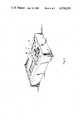
- FIG. 1is a perspective view of a central control unit for the security system of the present invention
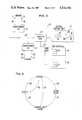
- FIG. 2is a block diagram of the central control unit in combination with a number of sensors at remote zones spaced from the central control unit and map displays near the control unit for simultaneously indicating the status of the sensors at the remote locations;
- FIG. 3is a block diagram of the components of the central control unit.
- FIG. 4is a graphic view of the sequence of steps in determining the status of a remote security zone and its sensor.
- the present inventioncomprises a multiplex monitor and display system and is broadly denoted by the numeral 10.
- System 10is adapted to provide status information relating to a plurality of remote, spaced security zones to be monitored, such as various locations throughout a warehouse or large plant.
- the systemcomprises a control unit 12 shown in FIGS. 1-3, the control unit adapted to be placed at a central location and including a housing 14 provided with a front panel 16.
- a liquid crystal display 18is mounted on panel 16 adjacent to three push button control switches 19, 20 and 22 (FIG. 3) having respective pushbuttons 24, 26 and 28 (FIG. 1) projecting outwardly from front panel 16.
- the control unitis comprised of a number of components, including a central processor 36, as shown in FIG. 3 which will hereinafter be described.
- FIG. 2shows control unit 12 coupled by a junction box 23 and a transponder bus 25 with a plurality of transponders 27, each transponder having a number of inputs 29 from sensors 31 at remote zones to be monitored by system 10.
- system 10can be provided with map displays 30, coupled by a map bus 32, to junction box 23 so that a visual display, such as displays formed by LED's 34, can be formed which represent the status of zones 31 whose sensors are coupled by leads 28 to the inputs of respective transponders 27.
- map display 30for each transponder 27, respectively, if desired.
- Control unit 12is shown in more detail in FIG. 3 and includes central processing unit 36, such as a 6802 CPU having an internal ram of 128 bytes.
- An address bus 38 and a data bus 40extend outwardly from the CPU and are coupled to other components of control unit 12.
- Address bus 38is coupled to an EPROM 42 which stores a program for operating system 10.
- a number of interface units 44are coupled to address bus 38 and data bus 40 and receive data from sensors 31 at respective, remote zones through opto-isolator units 46.
- the leads coupled with units 46form parts of transponder bus 25.
- a baud rate generator 48is coupled with interface units 44 to control the receipt of data directed thereto from opto-isolator units 46.
- Data bus 40is coupled with switches 19, 20 and 22 through a buffer 50.
- Switch 22has an LED 52 coupled with its push-button 28 (FIGS. 1 and 2) and this LED is coupled through an LED/sync latch 54 to address bus 38 and data bus 40.
- a sonic alert indicator 55also is coupled to data bus 40 through latch 54.
- FIG. 3also shows liquid crystal display 18 on the front panel 16 of housing 14.
- the liquid crystal displaycan display three 7-segment numerical digits in a central portion 56 of the display and can display seven different words. Three words can be displayed in a portion 57 to the left of central portion 56, and four words can be displayed in portion 59 to the right of central portion 56. These seven words are comfail, tamper, power, active, alarm, access and secure.
- Display latches 58, 60 and 62are coupled with the word portions 57 and 59 and central portion 56, respectively. Display latches 58 are coupled also to data bus 40.
- Control switches 19 and 20sequence the display of the identifying numbers assigned to various remote zones 31 up and down and cause changes in the numerals displayed by the digits in central portion 56 of display 18.
- Switch 22defines a system status switch which is actuated to change the status of a zone whose identifying number is displayed on display 18.
- control unit 12Immediately upon the application of power to system 10, control unit 12, under the control of central processor 36, scans bus 25 to determine which of the remote zones, which can be as many as 128 zones, are actually in the system. This scanning action is done by sequentially actuating status switch 22 by the operator and one of the two switches 19 and 20.
- each active zone in the systemis displayed in display 18 whenever an alarm event affects that zone.
- An alarm eventoccurs at a zone when the security sensor at that zone is actuated.
- Each sensorcan be of any desired construction.
- the sensor of each zonecan be an infrared detector, a magnetic switch, an ultrasonic motion detector, a smoke alarm, a floor sensor or a microwaver sensors. Other sensors can be used if desired. All system events displayed on display 18 are controlled by switches 19, 20 and 22 (FIG. 3) of control unit 12.
- each switch 19 or 20allows the operator to sequentially display the identifying numbers of all zones present in the system.
- switch 19When switch 19 is actuated, the display sequences identifying zone numbers in ascending order and when switch 20 is actuated, the display sequences down by descending identifying numbers of the zones.
- Switch 22has three functions, namely, to acknowledge an alarm event, to secure a zone, or to access a zone.
- LED 52 mounted on push button 52 as shown in FIGS. 1 and 2will flash and can be accompanied by a sound from sonic alert indicator 55 when an alarm event occurs. The LED will continue to flash and the sound alert indicator will continue to sound until the operator acknowledges the alarm event by actuating status switch 22.
- control unit 12When control unit 12 detects an alarm event at a remote zone, such as when the sensor at the zone sends a signal along bus 25 to control unit 12, CPU 36 receives the signal and causes specific data to be directed along data bus 40 to central portion 56 of display 18 so that the display will display the identifying number of the zone at which the alarm event occurs. Also, latch 54 is actuated to cause LED 52 to be energized and to flash. Sonic alert indicator 55 will also sound to warn of the alarm event. During an alarm event, the switches 19 and 20 are locked out so as to force the operator to acknowledge the alarm by actuating status switch 22. In the case of muliple alarms, the numbers of the various zones in alarm are displayed sequentially in central portion 56 of the display 18. Both the alarm and active words are flashed in portion 59 of display 18 when this occurs.
- the sonic alertis silenced and LED 52 is deactuated.
- the word "active" at portion 59 of display 18goes out and the zone can be secured by actuating the status switch 22. This action returns the zone to an access condition and the word "access” in portion 59 of display 18 will then be visible.
- the word “active” on display 18becomes visible whenever there is an alarm event at a zone and if the actuation of the sensor at the zone is continuous. The word “active” continues to be visible until the cause of that event has been corrected and the sensor is deactuated. If an alarm has been acknowledged and the active indicator appears in display 18, the zone having the alarm may be accessed by actuating status switch 22 one time. If the zone is in alarm, but the active indicator is not present, status switch 22 must be actuated two times, once to change the status of the zone from alarm to secure and a second time to change from secure to access. An alarmed or accessed zone may be secured by actuating status switch 22 when the identifying number of that zone appears in portion 56 of display 18.
- transponder 27ceases to respond to the actuation of status switch 22, such as during monitoring of the zones of the transponder, this will indicate that the line to the transponder is defective.
- the sonic alert indicator 55will sound and the identifying numbers of affected zones of that particular transponder 26 will be displayed sequentially on display 18 with their last known status. Then, the message "comfail" will appear in portion 57 of display 18.
- the transponder 26does eventually respond, the previous status of the zones will be restored.
- Control unit 12has a tamper annunciation portion and will detect a tamper alarm at junction box 23, if tampering does occur. In such a case, the sonic alert indicator 55 will sound and the word "tamper" in portion 57 of display 18 will become visible and will flash on the display. The alarm state is secured automatically when the tamper alarm is no longer detected. Tamper alarms cannot be manually secured or accessed. However, the tamper condition may be acknowledged to stop the sonic alert indicator 55 and allow the actuation of status switch 22.
- the sonic alert indicatorwill sound and the word "power" will be displayed at portion 57 of display 18. Operator acknowledgement is required to stop the sonic alert indicator and free the zone status switch 22 for use. When power is restored, the word "power" at portion 57 will go out.
- the map displays 30provide the operator with status information at a glance for each zone in the system.
- Each map display 30is a modular unit which can contain 16 sets of three color-coded LED's 34. For each zone, a red LED indicates alarm, a yellow LED indicates access, and a green LED indicates secure.
- the map displays 30can be rack mounted or can stand alone with control unit 12.
- FIG. 4shows in graphic form the sequence of events during an alarm event at a particular zone in which the status changes from secure to alarm status and then the return of the status of the zone to a secure condition, either directly or through an access event.
- each zonebefore an alarm event, will be in a secure condition indicated at portion 59 on display 18 by the word "secure”.
- the systemchanges from a secure status to an alarm event status indicated by the word "alarm” at portion 59 of display 18.
- Path 68 of FIG. 4indicates the change from the secure status to the alarm event. If the sensor comprises an alarm event, there will be a sound made by sonic alert indicator 55.
- LED 52 on pushbutton 28(FIGS.
- the operatorWhen the alarm event occurs, the operator will actuate switch 22 indicated by path 70 to acknowledge the alarm. When this occurs, the word “alarm” remains on the display 18, the sonic alert indicator 55 and LED 52 go off, and the red LED on the corresponding map display 30 will become a steady red. The operator can instruct a worker to go to the zone in alarm or can take other remedial action as required.
- actuation of switch 22will return the zone to secure along path 74 of FIG. 4. At this point, the system is returned to its starting condition awaiting the next alarm event. However, if the actuation of the sensor is continuous, such as when a door is opened and remains open, switch 22 is actuated and the sequence follows a path 76 to a location on the chart in FIG. 4 represented by the word "access”. When this condition is reached, the sonic alert indicator 55 is off and the yellow LED 34 of the corresponding map display 30 will be a steady yellow. Finally, the next actuation of status switch 22 will cause the sequence to follow along a path 80 of the chart in FIG.
- the status of the zone displayed on control unit 12the status of the sensor at the zone and the status of the map display will depend upon the conditions immediately before the second actuation of switch 22. If the status of the zone, sensor and map display are active alarm, alarm and steady red, respectively, then the second actuation of switch 22 causes the following conditions to occur:
- the sensorremains actuated, the word active remains visible in portion 59 of display 18 along with the word "access". In such a case, the sensor will continue to be in alarm rather than in secure. If the sensor is only momentarily actuated, it will be secure when the sensor is deactuated. When the zone is in access, entry to the zone can be made by a person without causing an alarm event.
Landscapes
- Physics & Mathematics (AREA)
- General Physics & Mathematics (AREA)
- Business, Economics & Management (AREA)
- Emergency Management (AREA)
- Engineering & Computer Science (AREA)
- Computer Security & Cryptography (AREA)
- Alarm Systems (AREA)
Abstract
Description
______________________________________ CONTROL UNIT SENSOR MAP STATUS STATUS DISPLAY ______________________________________ Secure Secure Green Active Alarm Alarm Flashing Red ______________________________________
______________________________________ CONTROL UNIT SENSOR MAP STATUS STATUS DISPLAY ______________________________________ (Active) Alarm (Alarm) Secure Steady Red ______________________________________
______________________________________ CONTROL UNIT SENSOR MAP STATUS STATUS DISPLAY ______________________________________ (Active) Access (Alarm) Secure Steady Yellow ______________________________________
______________________________________ CONTROL UNIT SENSOR MAP STATUS STATUS DISPLAY ______________________________________ Secure Secure Steady Green ______________________________________
Claims (7)
Priority Applications (1)
| Application Number | Priority Date | Filing Date | Title |
|---|---|---|---|
| US06/376,455US4524354A (en) | 1982-05-10 | 1982-05-10 | Apparatus and method for monitoring remote security zones |
Applications Claiming Priority (1)
| Application Number | Priority Date | Filing Date | Title |
|---|---|---|---|
| US06/376,455US4524354A (en) | 1982-05-10 | 1982-05-10 | Apparatus and method for monitoring remote security zones |
Publications (1)
| Publication Number | Publication Date |
|---|---|
| US4524354Atrue US4524354A (en) | 1985-06-18 |
Family
ID=23485099
Family Applications (1)
| Application Number | Title | Priority Date | Filing Date |
|---|---|---|---|
| US06/376,455Expired - LifetimeUS4524354A (en) | 1982-05-10 | 1982-05-10 | Apparatus and method for monitoring remote security zones |
Country Status (1)
| Country | Link |
|---|---|
| US (1) | US4524354A (en) |
Cited By (18)
| Publication number | Priority date | Publication date | Assignee | Title |
|---|---|---|---|---|
| USD283495S (en) | 1984-10-03 | 1986-04-22 | 3S S.A. | Antitheft unit |
| EP0294532A1 (en)* | 1986-04-11 | 1988-12-14 | ADT, Inc. | Integrity securing monitor and method for a security installation |
| WO1990003625A1 (en)* | 1988-09-23 | 1990-04-05 | Fike Corporation | Graphic annunciator |
| US4933668A (en)* | 1986-09-29 | 1990-06-12 | Shepherd Intelligence Systems, Inc. | Aircraft security system |
| US4952926A (en)* | 1988-04-29 | 1990-08-28 | Baker Industries, Inc. | Selective clearing of latched circuits |
| US5063371A (en)* | 1986-09-29 | 1991-11-05 | Oyer Michael W | Aircraft security system |
| US5379436A (en)* | 1991-05-01 | 1995-01-03 | Sony Corporation | Apparatus and method for responding to abnormal manipulations of an information processing system |
| US5400246A (en)* | 1989-05-09 | 1995-03-21 | Ansan Industries, Ltd. | Peripheral data acquisition, monitor, and adaptive control system via personal computer |
| US5485142A (en)* | 1994-04-08 | 1996-01-16 | The United States Of America As Represented By The Administrator Of The National Aeronautics And Space Administration | Remote monitor alarm system |
| US5646863A (en)* | 1994-03-22 | 1997-07-08 | Morton; Stephen G. | Method and apparatus for detecting and classifying contaminants in water |
| US5676820A (en)* | 1995-02-03 | 1997-10-14 | New Mexico State University Technology Transfer Corp. | Remote electrochemical sensor |
| US5689233A (en)* | 1994-07-29 | 1997-11-18 | Hitachi, Ltd. | Emergency information offering system |
| FR2756084A1 (en)* | 1996-11-18 | 1998-05-22 | Schneider Electric Sa | Intrusion detector system with several sensors linked to central controller |
| US5787429A (en)* | 1996-07-03 | 1998-07-28 | Nikolin, Jr.; Michael A. | Potential hazard and risk-assessment data communication network |
| US5867097A (en)* | 1995-08-18 | 1999-02-02 | Samsung Electronics Co., Ltd. | Method and apparatus for alarm signal processing |
| US5942103A (en)* | 1995-02-03 | 1999-08-24 | New Mexico State University Technology Transfer Corporation | Renewable-reagent electrochemical sensor |
| US6583720B1 (en)* | 1999-02-22 | 2003-06-24 | Early Warning Corporation | Command console for home monitoring system |
| US20080221495A1 (en)* | 2007-03-08 | 2008-09-11 | Steffens Brian J | Blood pump system user interface alarm management |
Citations (5)
| Publication number | Priority date | Publication date | Assignee | Title |
|---|---|---|---|---|
| US3958240A (en)* | 1973-03-06 | 1976-05-18 | Robertshaw Controls Company | Alarm and status monitoring system |
| US4023139A (en)* | 1974-10-24 | 1977-05-10 | Gene Samburg | Security control and alarm system |
| US4067008A (en)* | 1975-12-29 | 1978-01-03 | Denver Fire Reporter & Protective Co., Inc. | Multiplex interrogation system using pulses |
| US4117479A (en)* | 1976-04-16 | 1978-09-26 | American District Telegraph Company | Multi-mode intrusion alarm system |
| US4339746A (en)* | 1980-11-14 | 1982-07-13 | U.S. Philips Corporation | Alarm control center |
- 1982
- 1982-05-10USUS06/376,455patent/US4524354A/ennot_activeExpired - Lifetime
Patent Citations (5)
| Publication number | Priority date | Publication date | Assignee | Title |
|---|---|---|---|---|
| US3958240A (en)* | 1973-03-06 | 1976-05-18 | Robertshaw Controls Company | Alarm and status monitoring system |
| US4023139A (en)* | 1974-10-24 | 1977-05-10 | Gene Samburg | Security control and alarm system |
| US4067008A (en)* | 1975-12-29 | 1978-01-03 | Denver Fire Reporter & Protective Co., Inc. | Multiplex interrogation system using pulses |
| US4117479A (en)* | 1976-04-16 | 1978-09-26 | American District Telegraph Company | Multi-mode intrusion alarm system |
| US4339746A (en)* | 1980-11-14 | 1982-07-13 | U.S. Philips Corporation | Alarm control center |
Cited By (20)
| Publication number | Priority date | Publication date | Assignee | Title |
|---|---|---|---|---|
| USD283495S (en) | 1984-10-03 | 1986-04-22 | 3S S.A. | Antitheft unit |
| EP0294532A1 (en)* | 1986-04-11 | 1988-12-14 | ADT, Inc. | Integrity securing monitor and method for a security installation |
| US4933668A (en)* | 1986-09-29 | 1990-06-12 | Shepherd Intelligence Systems, Inc. | Aircraft security system |
| US5063371A (en)* | 1986-09-29 | 1991-11-05 | Oyer Michael W | Aircraft security system |
| US4952926A (en)* | 1988-04-29 | 1990-08-28 | Baker Industries, Inc. | Selective clearing of latched circuits |
| WO1990003625A1 (en)* | 1988-09-23 | 1990-04-05 | Fike Corporation | Graphic annunciator |
| US4933667A (en)* | 1988-09-23 | 1990-06-12 | Fike Corporation | Graphic annunciator |
| US5400246A (en)* | 1989-05-09 | 1995-03-21 | Ansan Industries, Ltd. | Peripheral data acquisition, monitor, and adaptive control system via personal computer |
| US5379436A (en)* | 1991-05-01 | 1995-01-03 | Sony Corporation | Apparatus and method for responding to abnormal manipulations of an information processing system |
| US5646863A (en)* | 1994-03-22 | 1997-07-08 | Morton; Stephen G. | Method and apparatus for detecting and classifying contaminants in water |
| US5485142A (en)* | 1994-04-08 | 1996-01-16 | The United States Of America As Represented By The Administrator Of The National Aeronautics And Space Administration | Remote monitor alarm system |
| US5689233A (en)* | 1994-07-29 | 1997-11-18 | Hitachi, Ltd. | Emergency information offering system |
| US5676820A (en)* | 1995-02-03 | 1997-10-14 | New Mexico State University Technology Transfer Corp. | Remote electrochemical sensor |
| US5942103A (en)* | 1995-02-03 | 1999-08-24 | New Mexico State University Technology Transfer Corporation | Renewable-reagent electrochemical sensor |
| US5867097A (en)* | 1995-08-18 | 1999-02-02 | Samsung Electronics Co., Ltd. | Method and apparatus for alarm signal processing |
| US5787429A (en)* | 1996-07-03 | 1998-07-28 | Nikolin, Jr.; Michael A. | Potential hazard and risk-assessment data communication network |
| FR2756084A1 (en)* | 1996-11-18 | 1998-05-22 | Schneider Electric Sa | Intrusion detector system with several sensors linked to central controller |
| US6583720B1 (en)* | 1999-02-22 | 2003-06-24 | Early Warning Corporation | Command console for home monitoring system |
| US20080221495A1 (en)* | 2007-03-08 | 2008-09-11 | Steffens Brian J | Blood pump system user interface alarm management |
| US8409124B2 (en)* | 2007-03-08 | 2013-04-02 | Medronic, Inc. | Blood pump system user interface alarm management |
Similar Documents
| Publication | Publication Date | Title |
|---|---|---|
| US4524354A (en) | Apparatus and method for monitoring remote security zones | |
| US5973662A (en) | Analog spectrum display for environmental control | |
| US4701849A (en) | System for summoning service personnel and monitoring their response time | |
| JPH02110692A (en) | Supervisory alarm unit | |
| JPS6239476B2 (en) | ||
| US4117479A (en) | Multi-mode intrusion alarm system | |
| GB2104697A (en) | Testing systems | |
| JP3014595B2 (en) | Fire alarm | |
| US4879547A (en) | Gas zone valve emergency alarm system | |
| JP2004280575A (en) | Fire receiver | |
| JP3279904B2 (en) | Remote monitoring system | |
| JP2886535B2 (en) | Self-fire alarm system | |
| JP2889063B2 (en) | Environmental monitoring device | |
| JP3305986B2 (en) | Disaster prevention display device | |
| JP3193782B2 (en) | Display operation device | |
| JP3288881B2 (en) | Security monitoring system and security monitoring control method | |
| JPH04133198A (en) | Fire sensor | |
| KR960006461A (en) | Automatic condition monitoring system of electronic exchange facility | |
| GB2290644A (en) | Graphical display for alarm system | |
| GB2251106A (en) | Multi-point detection systems | |
| JP2886581B2 (en) | Disaster prevention display device of disaster prevention system | |
| JP3380082B2 (en) | Fire alarm system | |
| CA1270307A (en) | System for summoning service personnel and monitoring their response time | |
| JP3330066B2 (en) | Alarm monitoring panel | |
| JPH0370983B2 (en) |
Legal Events
| Date | Code | Title | Description |
|---|---|---|---|
| AS | Assignment | Owner name:ATVIN ACQUISITION COMPANY, 1445 OAKLAND ROAD, SAN Free format text:ASSIGNMENT OF ASSIGNORS INTEREST.;ASSIGNORS:MORGAN, JACK B.;GUERRA, ANTHONY M.;VINDICATOR CORPORATION;REEL/FRAME:004688/0820 Effective date:19870318 Owner name:ATVIN ACQUISITION COMPANY,CALIFORNIA Free format text:ASSIGNMENT OF ASSIGNORS INTEREST;ASSIGNORS:MORGAN, JACK B.;GUERRA, ANTHONY M.;VINDICATOR CORPORATION;REEL/FRAME:004688/0820 Effective date:19870318 | |
| FEPP | Fee payment procedure | Free format text:PAYOR NUMBER ASSIGNED (ORIGINAL EVENT CODE: ASPN); ENTITY STATUS OF PATENT OWNER: LARGE ENTITY | |
| FPAY | Fee payment | Year of fee payment:4 | |
| FPAY | Fee payment | Year of fee payment:8 | |
| AS | Assignment | Owner name:GRC INTERNATIONAL, INC., VIRGINIA Free format text:ASSIGNMENT OF ASSIGNORS INTEREST;ASSIGNOR:VINDICATOR CORPORATION;REEL/FRAME:007846/0305 Effective date:19960229 | |
| FEPP | Fee payment procedure | Free format text:PETITION RELATED TO MAINTENANCE FEES FILED (ORIGINAL EVENT CODE: PMFP); ENTITY STATUS OF PATENT OWNER: LARGE ENTITY | |
| FEPP | Fee payment procedure | Free format text:PETITION RELATED TO MAINTENANCE FEES GRANTED (ORIGINAL EVENT CODE: PMFG); ENTITY STATUS OF PATENT OWNER: LARGE ENTITY | |
| REMI | Maintenance fee reminder mailed | ||
| REIN | Reinstatement after maintenance fee payment confirmed | ||
| AS | Assignment | Owner name:RAD PARTNERS, LTD., A TEXAS LIMITED PARTNERSHIP, T Free format text:ASSIGNMENT OF ASSIGNORS INTEREST;ASSIGNOR:GRC INTERNATIONAL, INC., A CORP. OF DELAWARE;REEL/FRAME:008613/0635 Effective date:19970605 | |
| AS | Assignment | Owner name:RAD PARTNERS, LTD. A TEXAS LIMITED PARTNERSHIP, TE Free format text:ASSIGNMENT OF ASSIGNORS INTEREST;ASSIGNOR:GRC INTERNATIONAL , INC. A DELAWARE CORPORATION;REEL/FRAME:008650/0888 Effective date:19970605 | |
| FPAY | Fee payment | Year of fee payment:12 | |
| SULP | Surcharge for late payment | ||
| FP | Lapsed due to failure to pay maintenance fee | Effective date:19970518 | |
| STCF | Information on status: patent grant | Free format text:PATENTED CASE | |
| PRDP | Patent reinstated due to the acceptance of a late maintenance fee | Effective date:19970926 |