US4523732A - Adjustable stand for optical observation instruments - Google Patents
Adjustable stand for optical observation instrumentsDownload PDFInfo
- Publication number
- US4523732A US4523732AUS06/302,710US30271081AUS4523732AUS 4523732 AUS4523732 AUS 4523732AUS 30271081 AUS30271081 AUS 30271081AUS 4523732 AUS4523732 AUS 4523732A
- Authority
- US
- United States
- Prior art keywords
- spring
- vertical bar
- elongate
- stand
- bar
- Prior art date
- Legal status (The legal status is an assumption and is not a legal conclusion. Google has not performed a legal analysis and makes no representation as to the accuracy of the status listed.)
- Expired - Fee Related
Links
- 230000003287optical effectEffects0.000titleclaimsabstractdescription7
- 230000007717exclusionEffects0.000claims2
- 230000000694effectsEffects0.000claims1
- 238000006073displacement reactionMethods0.000description9
- 238000010276constructionMethods0.000description5
- 230000006835compressionEffects0.000description4
- 238000007906compressionMethods0.000description4
- 238000010586diagramMethods0.000description4
- 230000035945sensitivityEffects0.000description3
- 230000006978adaptationEffects0.000description1
- 230000001771impaired effectEffects0.000description1
- 230000009347mechanical transmissionEffects0.000description1
- 238000005303weighingMethods0.000description1
Images


Classifications
- F—MECHANICAL ENGINEERING; LIGHTING; HEATING; WEAPONS; BLASTING
- F16—ENGINEERING ELEMENTS AND UNITS; GENERAL MEASURES FOR PRODUCING AND MAINTAINING EFFECTIVE FUNCTIONING OF MACHINES OR INSTALLATIONS; THERMAL INSULATION IN GENERAL
- F16M—FRAMES, CASINGS OR BEDS OF ENGINES, MACHINES OR APPARATUS, NOT SPECIFIC TO ENGINES, MACHINES OR APPARATUS PROVIDED FOR ELSEWHERE; STANDS; SUPPORTS
- F16M11/00—Stands or trestles as supports for apparatus or articles placed thereon ; Stands for scientific apparatus such as gravitational force meters
- F16M11/02—Heads
- F16M11/04—Means for attachment of apparatus; Means allowing adjustment of the apparatus relatively to the stand
- F16M11/043—Allowing translations
- F16M11/046—Allowing translations adapted to upward-downward translation movement
- F—MECHANICAL ENGINEERING; LIGHTING; HEATING; WEAPONS; BLASTING
- F16—ENGINEERING ELEMENTS AND UNITS; GENERAL MEASURES FOR PRODUCING AND MAINTAINING EFFECTIVE FUNCTIONING OF MACHINES OR INSTALLATIONS; THERMAL INSULATION IN GENERAL
- F16M—FRAMES, CASINGS OR BEDS OF ENGINES, MACHINES OR APPARATUS, NOT SPECIFIC TO ENGINES, MACHINES OR APPARATUS PROVIDED FOR ELSEWHERE; STANDS; SUPPORTS
- F16M11/00—Stands or trestles as supports for apparatus or articles placed thereon ; Stands for scientific apparatus such as gravitational force meters
- F16M11/02—Heads
- F16M11/04—Means for attachment of apparatus; Means allowing adjustment of the apparatus relatively to the stand
- F16M11/043—Allowing translations
- F16M11/048—Allowing translations adapted to forward-backward translation movement
- F—MECHANICAL ENGINEERING; LIGHTING; HEATING; WEAPONS; BLASTING
- F16—ENGINEERING ELEMENTS AND UNITS; GENERAL MEASURES FOR PRODUCING AND MAINTAINING EFFECTIVE FUNCTIONING OF MACHINES OR INSTALLATIONS; THERMAL INSULATION IN GENERAL
- F16M—FRAMES, CASINGS OR BEDS OF ENGINES, MACHINES OR APPARATUS, NOT SPECIFIC TO ENGINES, MACHINES OR APPARATUS PROVIDED FOR ELSEWHERE; STANDS; SUPPORTS
- F16M11/00—Stands or trestles as supports for apparatus or articles placed thereon ; Stands for scientific apparatus such as gravitational force meters
- F16M11/20—Undercarriages with or without wheels
- F16M11/2007—Undercarriages with or without wheels comprising means allowing pivoting adjustment
- F16M11/2014—Undercarriages with or without wheels comprising means allowing pivoting adjustment around a vertical axis
- F—MECHANICAL ENGINEERING; LIGHTING; HEATING; WEAPONS; BLASTING
- F16—ENGINEERING ELEMENTS AND UNITS; GENERAL MEASURES FOR PRODUCING AND MAINTAINING EFFECTIVE FUNCTIONING OF MACHINES OR INSTALLATIONS; THERMAL INSULATION IN GENERAL
- F16M—FRAMES, CASINGS OR BEDS OF ENGINES, MACHINES OR APPARATUS, NOT SPECIFIC TO ENGINES, MACHINES OR APPARATUS PROVIDED FOR ELSEWHERE; STANDS; SUPPORTS
- F16M11/00—Stands or trestles as supports for apparatus or articles placed thereon ; Stands for scientific apparatus such as gravitational force meters
- F16M11/42—Stands or trestles as supports for apparatus or articles placed thereon ; Stands for scientific apparatus such as gravitational force meters with arrangement for propelling the support stands on wheels
- G—PHYSICS
- G02—OPTICS
- G02B—OPTICAL ELEMENTS, SYSTEMS OR APPARATUS
- G02B21/00—Microscopes
- G02B21/0004—Microscopes specially adapted for specific applications
- G02B21/0012—Surgical microscopes
- G—PHYSICS
- G02—OPTICS
- G02B—OPTICAL ELEMENTS, SYSTEMS OR APPARATUS
- G02B7/00—Mountings, adjusting means, or light-tight connections, for optical elements
- G02B7/001—Counterbalanced structures, e.g. surgical microscopes
- F—MECHANICAL ENGINEERING; LIGHTING; HEATING; WEAPONS; BLASTING
- F16—ENGINEERING ELEMENTS AND UNITS; GENERAL MEASURES FOR PRODUCING AND MAINTAINING EFFECTIVE FUNCTIONING OF MACHINES OR INSTALLATIONS; THERMAL INSULATION IN GENERAL
- F16M—FRAMES, CASINGS OR BEDS OF ENGINES, MACHINES OR APPARATUS, NOT SPECIFIC TO ENGINES, MACHINES OR APPARATUS PROVIDED FOR ELSEWHERE; STANDS; SUPPORTS
- F16M2200/00—Details of stands or supports
- F16M2200/04—Balancing means
- F16M2200/041—Balancing means for balancing rotational movement of the head
- F—MECHANICAL ENGINEERING; LIGHTING; HEATING; WEAPONS; BLASTING
- F16—ENGINEERING ELEMENTS AND UNITS; GENERAL MEASURES FOR PRODUCING AND MAINTAINING EFFECTIVE FUNCTIONING OF MACHINES OR INSTALLATIONS; THERMAL INSULATION IN GENERAL
- F16M—FRAMES, CASINGS OR BEDS OF ENGINES, MACHINES OR APPARATUS, NOT SPECIFIC TO ENGINES, MACHINES OR APPARATUS PROVIDED FOR ELSEWHERE; STANDS; SUPPORTS
- F16M2200/00—Details of stands or supports
- F16M2200/06—Arms
- F16M2200/063—Parallelogram arms
- F—MECHANICAL ENGINEERING; LIGHTING; HEATING; WEAPONS; BLASTING
- F16—ENGINEERING ELEMENTS AND UNITS; GENERAL MEASURES FOR PRODUCING AND MAINTAINING EFFECTIVE FUNCTIONING OF MACHINES OR INSTALLATIONS; THERMAL INSULATION IN GENERAL
- F16M—FRAMES, CASINGS OR BEDS OF ENGINES, MACHINES OR APPARATUS, NOT SPECIFIC TO ENGINES, MACHINES OR APPARATUS PROVIDED FOR ELSEWHERE; STANDS; SUPPORTS
- F16M2200/00—Details of stands or supports
- F16M2200/06—Arms
- F16M2200/065—Arms with a special structure, e.g. reinforced or adapted for space reduction
Definitions
- the present inventionrelates to an adjustable stand having a stand base, a stand column and a supporting arm for optical observation instruments, particularly operation microscopes, wherein the supporting arm is developed as a four-bar linkage of the parallelogram variety.
- Operation microscopesmust be moved very precisely, both horizontally and vertically. Accordingly, it is necessary to compensate by a counterweight for the weight of the operation microscope carried by the stand. Since space is very limited at the operating table, a compact, self-contained stand construction is particularly desired.
- the object of the present inventionis to provide a stand with which the differing weights of different supported instruments can be rapidly and easily compensated by operating personnel, while requiring only minimum space and permitting a fine sensitivity adjustment of the instrument.
- Another object of the inventionis to accommodate supply lines (such as electric current leads, optical guides) in such manner as to achieve optimum reliability in operation and to assure no interference with the surgeon.
- the stand baseis to be imparted a shape which combines optimum stability with, if necessary, easy mobility of the stand.
- the inventionachieves these objects by providing an adjustable spring within the parallelogram, to compensate for the weight of the involved observation instrument.
- a closed structural form of the parallelogramis obtained by employing two parallel channels of U-shaped profile.
- the channelshave nested side walls and are displaceable with respect to each other, and they coact to define an enclosure for reception of the supply cables.
- Supply cables necessary for illuminating the observation instrument, as well as light guides,can be concealed and protected within the stand.
- the stand baseis advisedly of T-shape, with two rollers on each cross beam and one roller on the longitudinal beam.
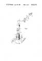
- FIG. 1is an overall view of a stand of the invention, adapted for adjustable-arm support of an observation instrument such as an operation microscope;
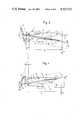
- FIG. 2is a view similar to FIG. 1, but partly broken-away and in partial section to reveal internal features;
- FIG. 3is a simplified diagram schematically showing components of the adjustable arm of the stand of FIG. 1, and involving an adjustable tension spring to compensate for instrument weight;
- FIG. 3ais a fragmentary diagram similar to FIG. 3, but showing an alternative embodiment
- FIG. 3bis a fragmentary vertical section to show further detail for the embodiment of FIG. 3;
- FIG. 4is a diagram similar to FIG. 3, to show an adjustable arm having a compression spring to compensate for instrument weight;
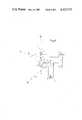
- FIG. 5is a fragmentary view in elevation, partly broken-away and in section through the stand column of the apparatus of FIG. 1;
- FIG. 6is a simplified diagram, viewed downwardly at the top of the stand column, to enable discussion of instrument support for various adjusted relationships.
- FIG. 1identifies the stand base, 2 the stand column, 3 slide-in units for the supply cables; the base 1 is of generally T shape, comprising a longitudinal beam Q and two transverse beams R, S. and 4 the compensating arm.
- a mount 5 for the observation instrument usedis part of the outer end of arm 4.
- the inner end of compensating arm 4is connected (on a vertical pivot axis) via a joint end 9, to a swivel arm 10, mounted for rotation about a vertical pin 8.
- the illustrative embodiment shown in FIGS. 1, 2 and 5is provided with a total of four slide-in supply units 3a to 3d.
- Slide-in unit 3ais for standard equipment; slide-in unit 3b accommodates special instruments, and light guides are supplied by slide-in-unit 3c.
- the slide-in unit 3dserves for photographic, motion-picture and television adaptation. If fewer slide-in units are required, the free openings can be closed by cover plates.
- the stand base 1is shown with floor rollers 6 and is equipped with a flexible power cable 7 and plug. 11 designates light guides, and various sockets 12b are provided for electronic supply of the instrument.
- An adjustment knob for the compensation springis designated 17.
- the supply cablesare designated 12a.
- the other designationsare the same as in FIG. 1.
- FIGS. 3 and 4show alternative spring means to provide adjustability of weight-compensation within the compensating arm 4.
- a tension spring 13is so arranged within elongate members 4a and 4b (developed as channels with U-shaped profiles) that upon displacement of the reference point P of spring attachment, the product of instrument weight G, times the length of weight arm r G , is equal to the product of spring force F F , times the length of force arm r F , i.e.,
- both the spring force F F and the force arm r Fmay be changed by displacement of the reference point P of spring attachment, in such manner that any given weight equalization is sufficiently constant for practical use over an arm-elevation adjustment angle ⁇ .
- the locus of point P as a function of compensated weightcan be determined by mathematical approximation calculations or empirically.
- the locus for Pis a straight line which forms an angle ⁇ of preferably 18° to 24° with the line a connecting the two points of articulation of the elongate members 4a and 4b; selective displacement of Point P is effected by adjustment knob 17 via a lead screw 19.
- FIG. 3the locus for P is a straight line which forms an angle ⁇ of preferably 18° to 24° with the line a connecting the two points of articulation of the elongate members 4a and 4b; selective displacement of Point P is effected by adjustment knob 17 via a lead screw 19.
- FIG. 3the locus for P is a straight line which forms an angle ⁇ of preferably 18
- selective displacement of point Pis effected by adjustment knob 17 via a lead screw 19; in FIG. 3a, selective displacement of point P is effected by adjustment knob 17' via a worm 19'.
- a compression spring 18reacts between the adjustable spring-reference point P and the upper-outer corner of the parallelogram linkage, and the lead screw 19 for adjustment of point P is inclined opposite to the slope discussed for the tension-spring arrangement of FIG. 3.
- Other partscorrespond to those identified in FIG. 3 and have therefore been given the same reference numbers.
- FIGS. 3 and 4are schematic and that for simplicity (i.e., better visibility) the point P of spring-referencing attachment is shown in both cases to be offset to the left of the vertical line a.
- the lead-screw actioni.e., locus of point P displaceability
- mechanical transmission membersnot shown.
- particularly precise equalization of weightcan be obtained for all angles of adjustment if an additional adjustment means is connected to one of the elongate members 4a or 4b to further control the displacement of point P as a function of the instantaneously selected elevation angle ⁇ .
- the described compensation spring meansbe it tension (FIG. 3) or compression (FIG. 4), has the advantage over prior-art use of gas springs, in that it operates virtually free of hysteresis and permits a compact, enclosed construction.
- the downward strokemay be limited by an adjustable stop 14 against which a swing arm 15 is engageable.
- the compensating arm 4is held fast at any desired height by a clamp at 16; in this connection, a bent bar of variable length b is clamped in a triangle with the fixed sides a and c.
- the entire inner cablingnot shown in FIG. 3, is readily accommodated.
- FIG. 5shows a partial section through the stand column and illustrates full utilization of the column 2, being equipped with four slide-in supply units. And a development of the stand base is shown for assurance of optimum stability, the position of the stand rollers being designated 6, and five rollers being used for the stand base, as shown in FIG. 6.
- the possible axis of tilt of the standare designated by aa, bb and cc, and the corresponding extreme orientations 10' and 4' of the swivel arm 10 and of the compensating arm 4 are designated by A, B and C.
- the angle of rotation of the swivel arm 10is limited to the angle ⁇ in order to assure stability.
- link parallelogramsFor expanded possibility of swing and stroke for the operation microscope, a double or multiple scissor arm is possible, two or more of the link parallelograms described working together.
- the link parallelogramscan be connected together rigidly or in articulated manner, as required.
Landscapes
- Engineering & Computer Science (AREA)
- General Engineering & Computer Science (AREA)
- Mechanical Engineering (AREA)
- Physics & Mathematics (AREA)
- General Physics & Mathematics (AREA)
- Optics & Photonics (AREA)
- Health & Medical Sciences (AREA)
- General Health & Medical Sciences (AREA)
- Surgery (AREA)
- Chemical & Material Sciences (AREA)
- Analytical Chemistry (AREA)
- Microscoopes, Condenser (AREA)
Abstract
Description
The present invention relates to an adjustable stand having a stand base, a stand column and a supporting arm for optical observation instruments, particularly operation microscopes, wherein the supporting arm is developed as a four-bar linkage of the parallelogram variety.
Operation microscopes must be moved very precisely, both horizontally and vertically. Accordingly, it is necessary to compensate by a counterweight for the weight of the operation microscope carried by the stand. Since space is very limited at the operating table, a compact, self-contained stand construction is particularly desired.
West German Pat. No. 2,161,396 and West German Pat. No. 2,320,266 disclose adjustable stands for optical observation instruments, wherein a counterweight is used to compensate for the weight of the apparatus. For example, for an apparatus weighing 15 kg, the counterweight must also weigh 15 kg, in order to obtain required sensitivity with the observation instrument. Despite optimum compensation for weight, a very heavy mass must, however, be moved by the user, requiring a greater or lesser amount of displacement depending on the speed of displacement. Furthermore, the compensation weight requires considerable free space for its unimpeded movement. Since the equipment of the instrument differs greatly, depending on its purpose of use and the particular requirements of an operation, the compensating-weight requirements necessarily also differ greatly. Precise compensation for instrument weight therefore places an additional demand on the persons using it.
Prospectus M1600-le-III.80 of Firma Wild of Heerbrugg, Germany, discloses a stand which uses a gas spring for weight compensation. This known stand has the disadvantage that an uncompensated residual moment remains, due to friction on the piston and the piston rod, as a result of which the sensitivity of the instrument is impaired. Furthermore, a gas spring is of an open, bulky construction, which is also undesired at the operating table.
The object of the present invention is to provide a stand with which the differing weights of different supported instruments can be rapidly and easily compensated by operating personnel, while requiring only minimum space and permitting a fine sensitivity adjustment of the instrument. Another object of the invention is to accommodate supply lines (such as electric current leads, optical guides) in such manner as to achieve optimum reliability in operation and to assure no interference with the surgeon. Furthermore, the stand base is to be imparted a shape which combines optimum stability with, if necessary, easy mobility of the stand.
The invention achieves these objects by providing an adjustable spring within the parallelogram, to compensate for the weight of the involved observation instrument.
A closed structural form of the parallelogram is obtained by employing two parallel channels of U-shaped profile. The channels have nested side walls and are displaceable with respect to each other, and they coact to define an enclosure for reception of the supply cables.
Increased reliability in handling is assured by providing an adjustable stop between the U-shaped profiles, to limit vertical movement of the parallelogram.
Supply cables necessary for illuminating the observation instrument, as well as light guides, can be concealed and protected within the stand.
The stand base is advisedly of T-shape, with two rollers on each cross beam and one roller on the longitudinal beam.
The advantages obtained with the invention reside particularly in the possibility of precise horizontal and vertical movements of the observation instrument, and in its closed, compact construction.
An illustrative embodiment of the invention will be described in further detail in conjunction with the accompanying drawings, in which:
FIG. 1 is an overall view of a stand of the invention, adapted for adjustable-arm support of an observation instrument such as an operation microscope;
FIG. 2 is a view similar to FIG. 1, but partly broken-away and in partial section to reveal internal features;
FIG. 3 is a simplified diagram schematically showing components of the adjustable arm of the stand of FIG. 1, and involving an adjustable tension spring to compensate for instrument weight;
FIG. 3a is a fragmentary diagram similar to FIG. 3, but showing an alternative embodiment;
FIG. 3b is a fragmentary vertical section to show further detail for the embodiment of FIG. 3;
FIG. 4 is a diagram similar to FIG. 3, to show an adjustable arm having a compression spring to compensate for instrument weight;
FIG. 5 is a fragmentary view in elevation, partly broken-away and in section through the stand column of the apparatus of FIG. 1; and
FIG. 6 is a simplified diagram, viewed downwardly at the top of the stand column, to enable discussion of instrument support for various adjusted relationships.
The compact space-saving construction of the stand can be clearly noted from the overall view shown in FIG. 1, wherein 1 identifies the stand base, 2 the stand column, 3 slide-in units for the supply cables; thebase 1 is of generally T shape, comprising a longitudinal beam Q and two transverse beams R, S. and 4 the compensating arm. Amount 5 for the observation instrument used is part of the outer end of arm 4. The inner end of compensating arm 4 is connected (on a vertical pivot axis) via ajoint end 9, to aswivel arm 10, mounted for rotation about avertical pin 8. The illustrative embodiment shown in FIGS. 1, 2 and 5 is provided with a total of four slide-insupply units 3a to 3d. Slide-inunit 3a is for standard equipment; slide-inunit 3b accommodates special instruments, and light guides are supplied by slide-in-unit 3c. The slide-inunit 3d serves for photographic, motion-picture and television adaptation. If fewer slide-in units are required, the free openings can be closed by cover plates. Thestand base 1 is shown withfloor rollers 6 and is equipped with aflexible power cable 7 and plug. 11 designates light guides, andvarious sockets 12b are provided for electronic supply of the instrument. An adjustment knob for the compensation spring is designated 17.
In the partial section of FIG. 2, the supply cables are designated 12a. The other designations are the same as in FIG. 1.
FIGS. 3 and 4 show alternative spring means to provide adjustability of weight-compensation within the compensating arm 4. In the form of FIG. 3, atension spring 13 is so arranged withinelongate members
G×r.sub.G =F.sub.F ×r.sub.F
For different weights G of the observation instrument, both the spring force FF and the force arm rF may be changed by displacement of the reference point P of spring attachment, in such manner that any given weight equalization is sufficiently constant for practical use over an arm-elevation adjustment angle ±α. The locus of point P as a function of compensated weight can be determined by mathematical approximation calculations or empirically. In one advantageous embodiment (as shown in FIG. 3), the locus for P is a straight line which forms an angle γ of preferably 18° to 24° with the line a connecting the two points of articulation of theelongate members adjustment knob 17 via alead screw 19. In another particularly advantageous embodiment (FIG. 3a), the locus for P is developed (by a worm wheel) as a circular arc having a radius of preferably 40 to 60 mm, the tangent at the point P forming an angle γ of 18° to 24° with the connecting line a, for the mid-position of elevation of the compensating arm 4, i.e., when α=0. In FIG. 3, selective displacement of point P is effected byadjustment knob 17 via alead screw 19; in FIG. 3a, selective displacement of point P is effected by adjustment knob 17' via a worm 19'.
In the compensating arm of FIG. 4, acompression spring 18 reacts between the adjustable spring-reference point P and the upper-outer corner of the parallelogram linkage, and thelead screw 19 for adjustment of point P is inclined opposite to the slope discussed for the tension-spring arrangement of FIG. 3. Other parts correspond to those identified in FIG. 3 and have therefore been given the same reference numbers.
It will be understood that FIGS. 3 and 4 are schematic and that for simplicity (i.e., better visibility) the point P of spring-referencing attachment is shown in both cases to be offset to the left of the vertical line a. For a sufficiently large angle of elevation adjustment of arm 4, it is preferred to position the lead-screw action (i.e., locus of point P displaceability) in the vicinity of the connecting line a, using mechanical transmission members (not shown). And particularly precise equalization of weight can be obtained for all angles of adjustment if an additional adjustment means is connected to one of theelongate members
It will be seen that the described compensation spring means, be it tension (FIG. 3) or compression (FIG. 4), has the advantage over prior-art use of gas springs, in that it operates virtually free of hysteresis and permits a compact, enclosed construction. The downward stroke may be limited by anadjustable stop 14 against which aswing arm 15 is engageable. The compensating arm 4 is held fast at any desired height by a clamp at 16; in this connection, a bent bar of variable length b is clamped in a triangle with the fixed sides a and c. Within the free space of the compensating arm, i.e., in the volume defined by and between side walls of theopposed channels
It will also be seen that if the involved range of elevation adjustment is limited to relatively small angles, the tension adjustment ofspring 13 or the compression adjustment ofspring 18 may be accomplished through displacement of point P only in the direction of the axis of the involved spring.
FIG. 5 shows a partial section through the stand column and illustrates full utilization of thecolumn 2, being equipped with four slide-in supply units. And a development of the stand base is shown for assurance of optimum stability, the position of the stand rollers being designated 6, and five rollers being used for the stand base, as shown in FIG. 6. The possible axis of tilt of the stand are designated by aa, bb and cc, and the corresponding extreme orientations 10' and 4' of theswivel arm 10 and of the compensating arm 4 are designated by A, B and C. The angle of rotation of theswivel arm 10 is limited to the angle ±β in order to assure stability.
For expanded possibility of swing and stroke for the operation microscope, a double or multiple scissor arm is possible, two or more of the link parallelograms described working together. The link parallelograms can be connected together rigidly or in articulated manner, as required.
Claims (10)
1. An adjustable stand having a stand base, a stand column and a support arm for supporting an operation microscope or the like observation instrument, said arm comprising a four-bar linkage establishing a parallelogram wherein (a) a first vertical bar is mounted to said column, (b) a second vertical bar is adapted to support the instrument, and (c) two vertically spaced parallel elongate bars have upper and lower pivoted connections to said vertical bars, spring-anchor means on said first vertical bar and including means for continuously adjustably positioning the same within a limited range of elevations between the elevations of elongate-bar connection thereto, and prestressed spring means connecting said spring-anchor means to said second vertical bar at one to the exclusion of the other of the points of elongate-bar connection to said second vertical bar, whereby said spring means may be essentially fully contained within the geometrical volume generally defined by and between said elongate bars; whereby for a limited range of elongate-bar angular elevation, said spring means may apply a counterbalancing elevational moment to said linkage, such counterbalancing moment varying as a function of elevation angle; and further whereby, within a limited range of weight of an observation instrument mounted to said second vertical bar, an observation instrument of given weight may be counterbalanced by selectively varied adjustment in the elevational position of said spring-anchor means, said spring-anchor means being adjustably displaceable on said first vertical bar along a straight line which forms an angle of 18° to 24° with the line connecting the upper and lower pivoted connections of said elongate bars to said first vertical bar, whereby adjustment of said spring-anchor means effects a change in moment-arm offset with accompanying relatively small change in spring force.
2. An adjustable stand according to claim 1, in which said two vertically spaced elongate bars are channel members having U-shaped profiles, the channel members having nested side walls and being displaceable with respect to each other.
3. An adjustable stand according to claim 2, characterized by the fact that between the U-shaped profiles there is provided an adjustable stop (14) which limits the vertical movement of the U-shaped profiles.
4. An adjustable stand according to claim 2, characterized by the fact that supply cables necessary for the observation instrument as well as optical guides are arranged invisibly within the stand and within the nested channel members of the parallelogram.
5. An adjustable stand according to claim 1, characterized by the fact that the stand base comprises a longitudinal beam with two oppositely directed transverse beams integrally united with one end of the longitudinal beam to thereby define a generally T shape, there being two spaced rollers in each of the transverse beams and one roller in the longitudinal beam at offset from said transverse beams.
6. An adjustable stand having a stand base, a stand column and a supporting arm for supporting an operation microscope or the like observation instrument, said arm comprising a four-bar linkage establishing a parallelogram wherein (a) a first vertical bar is mounted to said column, (b) a second vertical bar is adapted to support the instrument, and (c) two vertically spaced parallel elongate bars have upper and lower pivoted connections to said vertical bars, spring-anchor means at said first vertical bar and including means for continuously adjustably positioning the same within a limited range of elevations between the elevations of elongate-bar connection thereto, and prestressed spring means connecting said spring-anchor means to said second vertical bar at one to the exclusion of the other of the points of elongate-bar connection to said second vertical bar, whereby said spring means may be essentially fully contained within the geometrical volume generally defined by and between said elongate bars; whereby for a limited range of elongate-bar angular elevation, said spring means may apply a counterbalancing elevational moment to said linkage, such counterbalancing moment varying as a function of elevation angle; and further whereby, within a limited range of weight of an observation instrument mounted to said second vertical bar, an observation instrument of given weight may be counterbalanced by selectively varied adjustment in the elevational position of said spring-anchor means; said spring-anchor means being adjustably displaceable along a circular arc having a radius of preferably 40 to 60 mm, the tangent to the circular arc being inclined at an angle of 18° to 24° with the line connecting the upper and lower pivoted connections of said elongate bars to said first vertical bar.
7. An adjustable stand according to claim 6, in which said two vertically spaced elongate bars are channel members having U-shaped profiles, the channel members having nested side walls and being displaceable with respect to each other.
8. An adjustable stand according to claim 7, characterized by the fact that between the U-shaped profiles there is provided an adjustable stop (14) which limits the vertical movement of the U-shaped profiles.
9. An adjustable stand according to claim 7, characterized by the fact that supply cables necessary for the observation instrument as well as optical guides are arranged invisibly within the stand and within the nested channel members of the parallelogram.
10. An adjustable stand according to claim 6, characterized by the fact that the stand base comprises a longitudinal beam with two oppositely directed transverse beams integrally united with one end of the longitudinal beam to thereby define a generally T shape, there being two spaced rollers in each of the transverse beams and one roller in the longitudinal beam at offset from said transverse beams.
Applications Claiming Priority (2)
| Application Number | Priority Date | Filing Date | Title |
|---|---|---|---|
| DE3035165 | 1980-09-18 | ||
| DE3035165 | 1980-09-18 |
Publications (1)
| Publication Number | Publication Date |
|---|---|
| US4523732Atrue US4523732A (en) | 1985-06-18 |
Family
ID=6112243
Family Applications (1)
| Application Number | Title | Priority Date | Filing Date |
|---|---|---|---|
| US06/302,710Expired - Fee RelatedUS4523732A (en) | 1980-09-18 | 1981-09-16 | Adjustable stand for optical observation instruments |
Country Status (5)
| Country | Link |
|---|---|
| US (1) | US4523732A (en) |
| EP (1) | EP0048404B1 (en) |
| JP (1) | JPS5786806A (en) |
| BR (1) | BR8105947A (en) |
| DE (1) | DE3173714D1 (en) |
Cited By (54)
| Publication number | Priority date | Publication date | Assignee | Title |
|---|---|---|---|---|
| US4763864A (en)* | 1987-10-13 | 1988-08-16 | O'connor Engineering Laboratories | Floating column support pedestal |
| JPH02136211U (en)* | 1989-04-19 | 1990-11-14 | ||
| US5042763A (en)* | 1990-01-05 | 1991-08-27 | Wong William W M | Self-leveling portable camera support apparatus |
| US5048941A (en)* | 1988-10-07 | 1991-09-17 | Olympus Optical Co., Ltd. | Surgical miscroscope with a modular stand |
| US5054725A (en)* | 1989-09-01 | 1991-10-08 | Massimo Bucefari | Apparatus for maneuvering a tv camera remotely in special shooting conditions |
| US5108063A (en)* | 1990-11-01 | 1992-04-28 | Hill-Rom Company, Inc. | Hospital room computer mounting arm |
| US5316260A (en)* | 1992-10-19 | 1994-05-31 | Johnston Jack L | Ophthalmic instrument stand |
| US5609316A (en)* | 1995-09-05 | 1997-03-11 | Tigliev; George S. | Suspension system for surgical microscope |
| EP0816744A1 (en)* | 1996-06-28 | 1998-01-07 | Hill-Rom, Inc. | Monitor arm with constant counterbalance |
| US5746093A (en)* | 1995-03-11 | 1998-05-05 | Carl-Zeiss-Stiftung | Compensating device for compensation of a torque that depends on the angle of rotation, and medical stand with such a compensating device |
| WO1999001693A1 (en)* | 1997-06-30 | 1999-01-14 | Leica Mikroskopie Systeme Ag | Counterweight for stands |
| EP0930055A1 (en)* | 1998-01-15 | 1999-07-21 | Kaltenbach & Voigt Gmbh & Co. | Work table for medical or dental application |
| US6012821A (en)* | 1998-03-30 | 2000-01-11 | Hill-Rom, Inc. | Support arm for surgical light apparatus |
| EP1158238A1 (en)* | 2000-05-23 | 2001-11-28 | USM Holding AG | Holding device for apparatus |
| US6328458B1 (en) | 1998-03-30 | 2001-12-11 | Hill-Rom Services, Inc. | Support arm for surgical light apparatus |
| USD462359S1 (en) | 2000-05-23 | 2002-09-03 | Usm Holding Ag | Screen holding device |
| WO2003025453A1 (en)* | 2001-09-14 | 2003-03-27 | Hill-Rom Services, Inc. | Support arm for a surgical theater system |
| US20030230698A1 (en)* | 2002-05-18 | 2003-12-18 | Wolfgang Strauss | Carrier system for a medical apparatus |
| US20030234328A1 (en)* | 1999-06-07 | 2003-12-25 | Innovative Office Products, Inc. | Arm apparatus for mounting electronic devices with cable management system |
| US20040004170A1 (en)* | 1999-05-10 | 2004-01-08 | Innovative Office Products, Inc. | Arm apparatus for mounting electronic devices |
| US20040128766A1 (en)* | 2002-10-25 | 2004-07-08 | Brian Freeborn | Adjustable bed carriage |
| US20040188578A1 (en)* | 2001-09-14 | 2004-09-30 | Turner Jonathan D | Support arm for a surgical theater system |
| US20040199996A1 (en)* | 2003-03-18 | 2004-10-14 | Newkirk David C. | Radial arm system for patient care equipment |
| US20050057800A1 (en)* | 2002-12-09 | 2005-03-17 | Carl-Zeiss-Stiftung Trading As Carl Zeiss | Surgical microscopy system |
| US20050091747A1 (en)* | 2002-10-25 | 2005-05-05 | M.C. Healthcare Products Inc. | Adjustable bed carriage |
| US6915994B2 (en)* | 1999-06-07 | 2005-07-12 | Innovative Office Products, Inc. | Arm apparatus for mounting electronic devices with cable management system |
| US20050224670A1 (en)* | 2004-04-12 | 2005-10-13 | Andrzej Metelski | Stand, in particular for surgical microscopes, having an energy storage element |
| US20050224664A1 (en)* | 2004-04-12 | 2005-10-13 | Andrzej Metelski | Stand, in particular for surgical microscopes, having an energy storage element |
| US20060006297A1 (en)* | 2004-07-07 | 2006-01-12 | Innovative Office Products, Inc. | Arm apparatus with reinforcement |
| USD514478S1 (en) | 2003-10-21 | 2006-02-07 | M.C. Healthcare Products Inc. | Adjustable bed carriage |
| US20060073713A1 (en)* | 2004-09-22 | 2006-04-06 | Chance Richard W | Patient flatwall system |
| USD520511S1 (en)* | 2005-02-14 | 2006-05-09 | Steelcase Development Corporation | Support arm for a display |
| US20060258495A1 (en)* | 2005-04-15 | 2006-11-16 | Sachtler Gmbh & Co. Kg | Spring arm and body support |
| US20060263082A1 (en)* | 2005-04-15 | 2006-11-23 | Brown Garrett W | Equipoising support apparatus |
| US20060291044A1 (en)* | 2004-01-13 | 2006-12-28 | Olympus Corporation | Surgical microscope |
| US20070080275A1 (en)* | 2005-10-04 | 2007-04-12 | Garrett Brown | Apparatus for hand control, pressure amplification, and stabilization of medical and industrial devices |
| US20070156122A1 (en)* | 2005-01-24 | 2007-07-05 | Cooper Thomas G | Compact counter balance for robotic surgical systems |
| US20090314131A1 (en)* | 2008-06-23 | 2009-12-24 | Intuitive Surgical, Inc. | Spring Counterbalance for Rotating Load |
| US20100008854A1 (en)* | 2008-07-11 | 2010-01-14 | Seung Joo Haam | Metal nanocomposite, preparation method and use thereof |
| US7770860B1 (en)* | 2005-11-10 | 2010-08-10 | Modular Services Company | Medical service system on articulating arm with electromagnetic brakes |
| US8469323B1 (en)* | 2008-04-21 | 2013-06-25 | Yani Deros | Modular monitor support assembly |
| US8794579B2 (en) | 2005-06-03 | 2014-08-05 | Steelcase, Inc. | Support arm assembly |
| US8834489B2 (en) | 2005-01-24 | 2014-09-16 | Intuitive Surgical Operations, Inc. | Modular manipulator support for robotic surgery |
| US20160143167A1 (en)* | 2014-11-19 | 2016-05-19 | Hon Hai Precision Industry Co., Ltd. | Support device for a display |
| CN105759415A (en)* | 2016-05-13 | 2016-07-13 | 镇江市新天医疗器械有限公司 | Operating microscope mounting rack |
| CN105785562A (en)* | 2016-05-13 | 2016-07-20 | 镇江市新天医疗器械有限公司 | Surgical microscope suspension device |
| WO2016112452A1 (en)* | 2015-01-14 | 2016-07-21 | Centre For Imaging Technology Commercialization (Cimtec) | A counterbalance apparatus and/or method for supporting a load |
| CN105796191A (en)* | 2016-05-13 | 2016-07-27 | 镇江市新天医疗器械有限公司 | Operating microscope suspension mechanism |
| US20180112820A1 (en)* | 2016-10-21 | 2018-04-26 | Colebrook Bosson Saunders (Products) Limited | Display support system |
| US10695250B2 (en)* | 2012-07-24 | 2020-06-30 | Maquet (Suzhou) Co., Ltd. | Medical supply unit having an elbow joint part |
| CN115013666A (en)* | 2022-06-18 | 2022-09-06 | 江西登云健康美业互联有限公司 | A facial massage beauty instrument with adjustable function |
| US20230258226A1 (en)* | 2020-06-24 | 2023-08-17 | Ankon Medical Technologies (Shanghai) Co., Ltd. | Mechanical limiting mechanism |
| US11920759B2 (en) | 2021-04-09 | 2024-03-05 | Trumpf Medizin Systeme Gmbh + Co. Kg | Yoke for a suspension system for a medical lamp |
| US20240293192A1 (en)* | 2023-03-02 | 2024-09-05 | Alcon Inc. | Visualization robot with ophthalmic surgery-optimized kinematics |
Families Citing this family (20)
| Publication number | Priority date | Publication date | Assignee | Title |
|---|---|---|---|---|
| JPS59154219U (en)* | 1983-03-31 | 1984-10-16 | 株式会社 コムラ製作所 | support arm |
| US4720505A (en)* | 1983-06-27 | 1988-01-19 | Merck Frosst Canada, Inc. | Leukotriene antagonists |
| JPS6354156A (en)* | 1986-08-23 | 1988-03-08 | オリンパス光学工業株式会社 | Declining and elevating apparatus of operation microscope |
| JPS63187110U (en)* | 1987-05-18 | 1988-11-30 | ||
| DE3933343C2 (en)* | 1988-10-07 | 1996-11-14 | Olympus Optical Co | Surgical microscope |
| DE3921857A1 (en)* | 1989-07-04 | 1991-01-17 | Wild Leitz Ag | TRIPOD EQUIPPED WITH ADDITIONAL DEVICES FOR THE MOUNTING OF A FREELY POSITIONABLE DEVICE |
| US5257767A (en) | 1990-06-13 | 1993-11-02 | Waterloo Furniture Components, Ltd. | Adjustable support mechanism for a keyboard platform |
| DE4111408C2 (en)* | 1991-04-09 | 1993-10-21 | Rose Elektrotech Gmbh | Support arm for a control housing or a control panel |
| US5435515A (en)* | 1992-09-15 | 1995-07-25 | Garrett W. Brown | Adustable, iso-elastic support apparatus |
| DE4318659A1 (en)* | 1993-06-04 | 1994-12-08 | Kreuzer Gmbh & Co Ohg | Tripod with mass balance |
| US5579071A (en)* | 1994-03-21 | 1996-11-26 | Garrett W. Brown | Camera stabilizing support |
| DE19654302A1 (en)* | 1996-12-24 | 1998-06-25 | Moeller J D Optik | Suspension for a surgical microscope |
| DE10142564A1 (en)† | 2000-09-30 | 2002-04-11 | Zeiss Carl | Support for mounting a medical equipment, e.g. for holding an operation microscope |
| DE10163354A1 (en)* | 2001-12-21 | 2003-07-03 | Leica Microsystems | Device for holding an optical viewing device |
| JP4488292B2 (en) | 2004-03-03 | 2010-06-23 | オリンパス株式会社 | Surgical microscope |
| DE102006033054A1 (en)* | 2006-07-14 | 2008-01-17 | Carl Zeiss Surgical Gmbh | Ophthalmic surgical workstation |
| EP2540210B1 (en) | 2010-07-29 | 2015-05-27 | Olympus Medical Systems Corp. | Medical instrument holding device |
| CN107421497A (en)* | 2017-09-09 | 2017-12-01 | 衢州万鹏环境建设有限公司 | A kind of architectural engineering horizontal calibrator |
| DE102020211130A1 (en) | 2020-09-03 | 2022-03-03 | Carl Zeiss Meditec Ag | Method and device for balancing a microscopy system |
| CN114568885B (en)* | 2022-03-15 | 2023-05-02 | 江苏电子信息职业学院 | Multi-angle viewing display device for design |
Citations (8)
| Publication number | Priority date | Publication date | Assignee | Title |
|---|---|---|---|---|
| US198655A (en)* | 1877-12-25 | Improvement in tilting chairs | ||
| US598105A (en)* | 1898-02-01 | Counter-stool | ||
| US911935A (en)* | 1908-05-23 | 1909-02-09 | Fletcher T Smallwood | Rural mail-box. |
| US2967458A (en)* | 1957-05-16 | 1961-01-10 | Jr William Stone | Instrument for use by a surgeon in viewing the field of operation under magnification |
| DE1405783A1 (en)* | 1960-01-23 | 1969-10-23 | Bruns Werkzeugfab Gmbh C | Adjustment device for vibration suspension, especially of vehicle seats |
| US3973748A (en)* | 1975-01-31 | 1976-08-10 | Konan Camera Research Institute | Sustaining device |
| US4339100A (en)* | 1979-07-24 | 1982-07-13 | Contraves Ag | Arrangement at a stand for an optical observation device |
| US4344595A (en)* | 1979-07-24 | 1982-08-17 | Contraves Ag | Auxiliary apparatus at a stand for an optical observation device |
Family Cites Families (6)
| Publication number | Priority date | Publication date | Assignee | Title |
|---|---|---|---|---|
| DE1048474B (en)* | 1959-01-08 | |||
| DE616538C (en)* | 1933-04-02 | 1935-07-31 | Leitz Ernst Gmbh | Device for focal length compensation on enlarging devices with automatic focusing |
| DE860447C (en)* | 1942-01-04 | 1952-12-22 | Agfa Camera Werk Muenchen | Enlargement device with a parallelogram lever linkage |
| DE1713867U (en)* | 1955-08-30 | 1955-12-29 | Leitz Ernst Gmbh | ENLARGEMENT DEVICE WITH AUTOMATIC FOCUSING. |
| US3776614A (en)* | 1972-03-01 | 1973-12-04 | Applied Fiberoptics | Microscope with remote image system |
| DE2604927C2 (en)* | 1976-02-09 | 1982-04-01 | Ernst Leitz Wetzlar Gmbh, 6330 Wetzlar | Device for guiding the projection head in an enlarger |
- 1981
- 1981-09-10EPEP81107127Apatent/EP0048404B1/ennot_activeExpired
- 1981-09-10DEDE8181107127Tpatent/DE3173714D1/ennot_activeExpired
- 1981-09-16USUS06/302,710patent/US4523732A/ennot_activeExpired - Fee Related
- 1981-09-17JPJP56145642Apatent/JPS5786806A/enactivePending
- 1981-09-17BRBR8105947Apatent/BR8105947A/enunknown
Patent Citations (8)
| Publication number | Priority date | Publication date | Assignee | Title |
|---|---|---|---|---|
| US198655A (en)* | 1877-12-25 | Improvement in tilting chairs | ||
| US598105A (en)* | 1898-02-01 | Counter-stool | ||
| US911935A (en)* | 1908-05-23 | 1909-02-09 | Fletcher T Smallwood | Rural mail-box. |
| US2967458A (en)* | 1957-05-16 | 1961-01-10 | Jr William Stone | Instrument for use by a surgeon in viewing the field of operation under magnification |
| DE1405783A1 (en)* | 1960-01-23 | 1969-10-23 | Bruns Werkzeugfab Gmbh C | Adjustment device for vibration suspension, especially of vehicle seats |
| US3973748A (en)* | 1975-01-31 | 1976-08-10 | Konan Camera Research Institute | Sustaining device |
| US4339100A (en)* | 1979-07-24 | 1982-07-13 | Contraves Ag | Arrangement at a stand for an optical observation device |
| US4344595A (en)* | 1979-07-24 | 1982-08-17 | Contraves Ag | Auxiliary apparatus at a stand for an optical observation device |
Non-Patent Citations (2)
| Title |
|---|
| Wild Heerbrugg, Ltd., Prospectus "Wild Series M600", M 1600-1e-III.80. |
| Wild Heerbrugg, Ltd., Prospectus Wild Series M600 , M 1600 1e III.80.* |
Cited By (113)
| Publication number | Priority date | Publication date | Assignee | Title |
|---|---|---|---|---|
| US4763864A (en)* | 1987-10-13 | 1988-08-16 | O'connor Engineering Laboratories | Floating column support pedestal |
| US5048941A (en)* | 1988-10-07 | 1991-09-17 | Olympus Optical Co., Ltd. | Surgical miscroscope with a modular stand |
| JPH02136211U (en)* | 1989-04-19 | 1990-11-14 | ||
| US5054725A (en)* | 1989-09-01 | 1991-10-08 | Massimo Bucefari | Apparatus for maneuvering a tv camera remotely in special shooting conditions |
| US5042763A (en)* | 1990-01-05 | 1991-08-27 | Wong William W M | Self-leveling portable camera support apparatus |
| US5108063A (en)* | 1990-11-01 | 1992-04-28 | Hill-Rom Company, Inc. | Hospital room computer mounting arm |
| US5316260A (en)* | 1992-10-19 | 1994-05-31 | Johnston Jack L | Ophthalmic instrument stand |
| US5746093A (en)* | 1995-03-11 | 1998-05-05 | Carl-Zeiss-Stiftung | Compensating device for compensation of a torque that depends on the angle of rotation, and medical stand with such a compensating device |
| US5609316A (en)* | 1995-09-05 | 1997-03-11 | Tigliev; George S. | Suspension system for surgical microscope |
| EP0816744A1 (en)* | 1996-06-28 | 1998-01-07 | Hill-Rom, Inc. | Monitor arm with constant counterbalance |
| US5826846A (en)* | 1996-06-28 | 1998-10-27 | Hill-Rom, Inc. | Monitor arm with constant counterbalance |
| WO1999001693A1 (en)* | 1997-06-30 | 1999-01-14 | Leica Mikroskopie Systeme Ag | Counterweight for stands |
| US6247673B1 (en) | 1997-06-30 | 2001-06-19 | Leica Microsystems Ag | Counterweight for stands |
| CN1106521C (en)* | 1997-06-30 | 2003-04-23 | 莱卡显微镜系统股份公司 | Weight Balance of the Tripod |
| EP0930055A1 (en)* | 1998-01-15 | 1999-07-21 | Kaltenbach & Voigt Gmbh & Co. | Work table for medical or dental application |
| DE19801314C2 (en)* | 1998-01-15 | 2001-11-08 | Kaltenbach & Voigt | Medical or dental work table |
| US6012821A (en)* | 1998-03-30 | 2000-01-11 | Hill-Rom, Inc. | Support arm for surgical light apparatus |
| US6328458B1 (en) | 1998-03-30 | 2001-12-11 | Hill-Rom Services, Inc. | Support arm for surgical light apparatus |
| US6983917B2 (en) | 1999-05-10 | 2006-01-10 | Innovative Office Products, Inc. | Arm apparatus for mounting electronic devices |
| US20040004170A1 (en)* | 1999-05-10 | 2004-01-08 | Innovative Office Products, Inc. | Arm apparatus for mounting electronic devices |
| US7677516B2 (en) | 1999-05-10 | 2010-03-16 | Innovative Office Products, Inc. | Arm apparatus for mounting electronic devices |
| US7059574B2 (en) | 1999-05-10 | 2006-06-13 | Innovative Office Products, Inc. | Arm apparatus for mounting electronic devices |
| US6854698B2 (en) | 1999-05-10 | 2005-02-15 | Innovative Office Products, Inc. | Arm apparatus for mounting electronic devices |
| US20050023422A1 (en)* | 1999-05-10 | 2005-02-03 | Oddsen Odd N. | Arm apparatus for mounting electronic devices |
| US20050001120A1 (en)* | 1999-05-10 | 2005-01-06 | Oddsen Odd N. | Arm apparatus for mounting electronic devices |
| US7017874B2 (en) | 1999-05-10 | 2006-03-28 | Innovative Office Products, Inc. | Arm apparatus for mounting electronic devices |
| US20030234328A1 (en)* | 1999-06-07 | 2003-12-25 | Innovative Office Products, Inc. | Arm apparatus for mounting electronic devices with cable management system |
| US6915994B2 (en)* | 1999-06-07 | 2005-07-12 | Innovative Office Products, Inc. | Arm apparatus for mounting electronic devices with cable management system |
| US20040222344A1 (en)* | 1999-06-07 | 2004-11-11 | Oddsen Odd N. | Arm apparatus for mounting electronic devices with cable management system |
| US7066433B2 (en) | 1999-06-07 | 2006-06-27 | Innovation Office Products, Inc. | Arm apparatus for mounting electronic devices with cable management system |
| US7100880B2 (en) | 1999-06-07 | 2006-09-05 | Innovative Office Products, Inc. | Arm apparatus for mounting electronic devices with cable management system |
| USD462969S1 (en) | 2000-05-23 | 2002-09-17 | Usm Holding Ag | Screen holding device |
| EP1158238A1 (en)* | 2000-05-23 | 2001-11-28 | USM Holding AG | Holding device for apparatus |
| WO2001090630A1 (en) | 2000-05-23 | 2001-11-29 | Usm Holding Ag | Apparatus mounting device |
| USD472556S1 (en) | 2000-05-23 | 2003-04-01 | Usm Holding Ag | Screen holding device |
| USD462359S1 (en) | 2000-05-23 | 2002-09-03 | Usm Holding Ag | Screen holding device |
| US7097145B2 (en) | 2001-09-14 | 2006-08-29 | Hill-Rom Services, Inc. | Support arm for a surgical theater system |
| WO2003025453A1 (en)* | 2001-09-14 | 2003-03-27 | Hill-Rom Services, Inc. | Support arm for a surgical theater system |
| US20040188578A1 (en)* | 2001-09-14 | 2004-09-30 | Turner Jonathan D | Support arm for a surgical theater system |
| US6899307B2 (en)* | 2002-05-18 | 2005-05-31 | Carl-Zeiss-Stiftung | Carrier system for a medical apparatus |
| US20050109903A1 (en)* | 2002-05-18 | 2005-05-26 | Carl Stiftung | Carrier system for a medical apparatus |
| US20070012853A1 (en)* | 2002-05-18 | 2007-01-18 | Carl-Zeiss-Stiftung | Carrier system for a medical apparatus |
| US20030230698A1 (en)* | 2002-05-18 | 2003-12-18 | Wolfgang Strauss | Carrier system for a medical apparatus |
| US7219864B2 (en) | 2002-05-18 | 2007-05-22 | Carl-Zeiss-Stiftung | Carrier system for a medical apparatus |
| US6941600B2 (en) | 2002-10-25 | 2005-09-13 | M.C. Healthcare Products Inc. | Adjustable bed carriage |
| US20050091747A1 (en)* | 2002-10-25 | 2005-05-05 | M.C. Healthcare Products Inc. | Adjustable bed carriage |
| US20040128766A1 (en)* | 2002-10-25 | 2004-07-08 | Brian Freeborn | Adjustable bed carriage |
| US7134155B2 (en) | 2002-10-25 | 2006-11-14 | M.C. Healthcare Products Inc. | Adjustable bed carriage |
| US20070258135A1 (en)* | 2002-12-09 | 2007-11-08 | Andreas Obrebski | Surgical microscopy system |
| US7248402B2 (en) | 2002-12-09 | 2007-07-24 | Carl Zeiss Surgical Gmbh | Surgical microscopy system |
| US20050057800A1 (en)* | 2002-12-09 | 2005-03-17 | Carl-Zeiss-Stiftung Trading As Carl Zeiss | Surgical microscopy system |
| US7254850B2 (en) | 2003-03-18 | 2007-08-14 | Hill-Rom Services, Inc. | Radial arm system for patient care equipment |
| US8336138B2 (en) | 2003-03-18 | 2012-12-25 | Hill-Rom Services, Inc. | Radial arm system for patient care equipment |
| US7065811B2 (en) | 2003-03-18 | 2006-06-27 | Hill-Rom Services, Inc. | Radial arm system for patient care equipment |
| US7921489B2 (en) | 2003-03-18 | 2011-04-12 | Hill-Rom Services, Inc. | Radial arm system for patient care equipment |
| US20040199996A1 (en)* | 2003-03-18 | 2004-10-14 | Newkirk David C. | Radial arm system for patient care equipment |
| USD514478S1 (en) | 2003-10-21 | 2006-02-07 | M.C. Healthcare Products Inc. | Adjustable bed carriage |
| US20060291044A1 (en)* | 2004-01-13 | 2006-12-28 | Olympus Corporation | Surgical microscope |
| US7283296B2 (en) | 2004-01-13 | 2007-10-16 | Olympus Corporation | Surgical microscope |
| US20050224670A1 (en)* | 2004-04-12 | 2005-10-13 | Andrzej Metelski | Stand, in particular for surgical microscopes, having an energy storage element |
| EP1586925A1 (en)* | 2004-04-12 | 2005-10-19 | Leica Microsystems (Schweiz) AG | Stand, in particular for surgical microscopes, having an energy storage element |
| US20050224664A1 (en)* | 2004-04-12 | 2005-10-13 | Andrzej Metelski | Stand, in particular for surgical microscopes, having an energy storage element |
| US7255311B2 (en)* | 2004-04-12 | 2007-08-14 | Leica Microsystems (Schweiz) Ag | Stand, in particular for surgical microscopes, having an energy storage element |
| US7677515B2 (en) | 2004-07-07 | 2010-03-16 | Innovative Office Products, Inc. | Arm apparatus with reinforcement |
| US20060006297A1 (en)* | 2004-07-07 | 2006-01-12 | Innovative Office Products, Inc. | Arm apparatus with reinforcement |
| US8051610B2 (en) | 2004-09-22 | 2011-11-08 | Hill-Rom Services, Inc. | Patient flatwall system |
| US8678334B2 (en) | 2004-09-22 | 2014-03-25 | Hill-Rom Services, Inc. | Patient flatwall system |
| US20060073713A1 (en)* | 2004-09-22 | 2006-04-06 | Chance Richard W | Patient flatwall system |
| US7837674B2 (en) | 2005-01-24 | 2010-11-23 | Intuitive Surgical Operations, Inc. | Compact counter balance for robotic surgical systems |
| US9291793B2 (en) | 2005-01-24 | 2016-03-22 | Intuitive Surgical Operations, Inc. | Apparatus for compact counter balance arms |
| US9023060B2 (en) | 2005-01-24 | 2015-05-05 | Intuitive Surgical Operations, Inc. | Modular manipulator support for robotic surgery |
| US8834489B2 (en) | 2005-01-24 | 2014-09-16 | Intuitive Surgical Operations, Inc. | Modular manipulator support for robotic surgery |
| US9877792B2 (en) | 2005-01-24 | 2018-01-30 | Intuitive Surgical Operations, Inc. | Compact counter balanced arms |
| US10898281B2 (en) | 2005-01-24 | 2021-01-26 | Intuitive Surgical Operations, Inc. | Modular manipulator support for robotic surgery |
| US9968405B2 (en) | 2005-01-24 | 2018-05-15 | Intuitive Surgical Operations, Inc. | Modular manipulator support for robotic surgery |
| US20110023651A1 (en)* | 2005-01-24 | 2011-02-03 | Intuitive Surgical Operations, Inc. | Apparatus for compact counter balance arms |
| US20110023285A1 (en)* | 2005-01-24 | 2011-02-03 | Intuitive Surgical Operations, Inc. | Methods for compact counter balance arms |
| US20070156122A1 (en)* | 2005-01-24 | 2007-07-05 | Cooper Thomas G | Compact counter balance for robotic surgical systems |
| US10786318B2 (en) | 2005-01-24 | 2020-09-29 | Intuitive Surgical Operations, Inc. | Compact counter balanced arm |
| US8500722B2 (en) | 2005-01-24 | 2013-08-06 | Intuitive Surgical Operations, Inc. | Methods for compact counter balance arms |
| USD520511S1 (en)* | 2005-02-14 | 2006-05-09 | Steelcase Development Corporation | Support arm for a display |
| US20060258495A1 (en)* | 2005-04-15 | 2006-11-16 | Sachtler Gmbh & Co. Kg | Spring arm and body support |
| US7618016B2 (en) | 2005-04-15 | 2009-11-17 | Brown Garrett W | Equipoising support apparatus |
| EP1712828A3 (en)* | 2005-04-15 | 2007-03-28 | Sachtler GmbH & Co. KG | Body-mounted support |
| US20060263082A1 (en)* | 2005-04-15 | 2006-11-23 | Brown Garrett W | Equipoising support apparatus |
| US8066251B2 (en) | 2005-04-15 | 2011-11-29 | Brown Garrett W | Equipoising support apparatus |
| US7562851B2 (en) | 2005-04-15 | 2009-07-21 | Camera Dynamics Gmbh | Spring arm and body support |
| US8794579B2 (en) | 2005-06-03 | 2014-08-05 | Steelcase, Inc. | Support arm assembly |
| US8342467B2 (en)* | 2005-10-04 | 2013-01-01 | Eric Ronald Stachowski | Apparatus for hand control, pressure amplification, and stabilization of medical and industrial devices |
| US20070080275A1 (en)* | 2005-10-04 | 2007-04-12 | Garrett Brown | Apparatus for hand control, pressure amplification, and stabilization of medical and industrial devices |
| US9010709B1 (en)* | 2005-11-10 | 2015-04-21 | Modular Services Company | Medical service system on articulating arm with electromagnetic brakes |
| US7770860B1 (en)* | 2005-11-10 | 2010-08-10 | Modular Services Company | Medical service system on articulating arm with electromagnetic brakes |
| US8469323B1 (en)* | 2008-04-21 | 2013-06-25 | Yani Deros | Modular monitor support assembly |
| US20090314131A1 (en)* | 2008-06-23 | 2009-12-24 | Intuitive Surgical, Inc. | Spring Counterbalance for Rotating Load |
| US8220765B2 (en) | 2008-06-23 | 2012-07-17 | Intuitive Surgical Operations, Inc. | Spring counterbalance for rotating load |
| US20100008854A1 (en)* | 2008-07-11 | 2010-01-14 | Seung Joo Haam | Metal nanocomposite, preparation method and use thereof |
| US10695250B2 (en)* | 2012-07-24 | 2020-06-30 | Maquet (Suzhou) Co., Ltd. | Medical supply unit having an elbow joint part |
| US9575346B2 (en)* | 2014-11-19 | 2017-02-21 | Hon Hai Precision Industry Co., Ltd. | Support device for a display device |
| US20160143167A1 (en)* | 2014-11-19 | 2016-05-19 | Hon Hai Precision Industry Co., Ltd. | Support device for a display |
| WO2016112452A1 (en)* | 2015-01-14 | 2016-07-21 | Centre For Imaging Technology Commercialization (Cimtec) | A counterbalance apparatus and/or method for supporting a load |
| US10066782B2 (en) | 2015-01-14 | 2018-09-04 | Centre For Imaging Technology Commercialization (Cimtec) | Counterbalance apparatus and/or method for supporting a load |
| CN105796191A (en)* | 2016-05-13 | 2016-07-27 | 镇江市新天医疗器械有限公司 | Operating microscope suspension mechanism |
| CN105759415B (en)* | 2016-05-13 | 2018-04-03 | 镇江市新天医疗器械有限公司 | A kind of surgical operation microscope mounting bracket |
| CN105785562A (en)* | 2016-05-13 | 2016-07-20 | 镇江市新天医疗器械有限公司 | Surgical microscope suspension device |
| CN105759415A (en)* | 2016-05-13 | 2016-07-13 | 镇江市新天医疗器械有限公司 | Operating microscope mounting rack |
| US10845000B2 (en)* | 2016-10-21 | 2020-11-24 | Colebrook Bosson Saunders (Products) Limited | Display support system |
| US20180112820A1 (en)* | 2016-10-21 | 2018-04-26 | Colebrook Bosson Saunders (Products) Limited | Display support system |
| US20230258226A1 (en)* | 2020-06-24 | 2023-08-17 | Ankon Medical Technologies (Shanghai) Co., Ltd. | Mechanical limiting mechanism |
| US11920759B2 (en) | 2021-04-09 | 2024-03-05 | Trumpf Medizin Systeme Gmbh + Co. Kg | Yoke for a suspension system for a medical lamp |
| US12188641B2 (en) | 2021-04-09 | 2025-01-07 | Trumpe Medizin Systeme Gmbh + Co. Kg | Yoke for a suspension system for a medical lamp |
| CN115013666A (en)* | 2022-06-18 | 2022-09-06 | 江西登云健康美业互联有限公司 | A facial massage beauty instrument with adjustable function |
| US20240293192A1 (en)* | 2023-03-02 | 2024-09-05 | Alcon Inc. | Visualization robot with ophthalmic surgery-optimized kinematics |
| WO2024180528A1 (en)* | 2023-03-02 | 2024-09-06 | Alcon Inc. | Visualization robot with ophthalmic surgery-optimized kinematics |
Also Published As
| Publication number | Publication date |
|---|---|
| BR8105947A (en) | 1982-06-08 |
| EP0048404B1 (en) | 1986-02-05 |
| JPS5786806A (en) | 1982-05-31 |
| DE3173714D1 (en) | 1986-03-20 |
| EP0048404A1 (en) | 1982-03-31 |
Similar Documents
| Publication | Publication Date | Title |
|---|---|---|
| US4523732A (en) | Adjustable stand for optical observation instruments | |
| US4166602A (en) | Counterbalancing mechanism for X-ray tubeheads | |
| US5173803A (en) | Pivoting device for supporting frames for optical observation equipment | |
| US5213293A (en) | Stand equipped with accessory devices for supporting a freely orientable apparatus | |
| CA1132961A (en) | Auxiliary apparatus at a stand for an optical observation device | |
| US5173802A (en) | Counterbalanced supporting frame for a surgical microscope | |
| US5348260A (en) | Movable supporting arm | |
| US4708312A (en) | Extensible height-adjustable swivel arm for supporting a display or the like | |
| US4082244A (en) | Counterbalancing supporting device | |
| US4684088A (en) | Support apparatus for an optical observation device | |
| US4768744A (en) | Apparatus for supporting a load in a dynamically balanced condition | |
| US5845587A (en) | Two-part table top | |
| US4657220A (en) | Television camera mounting equipment | |
| GB2230946A (en) | Adjustable CRT support stand | |
| CA1209114A (en) | Computer terminal stand | |
| JP2002136527A (en) | Frame apparatus | |
| US7207531B2 (en) | Head manipulable binocular microscope support | |
| US4277044A (en) | Mechanical counterbalance | |
| EP0293227A2 (en) | Stand mechanism for a medical optical equipment | |
| US5713545A (en) | Stand apparatus for medical optical equipments | |
| US4318538A (en) | Counterbalanced support | |
| JP4229844B2 (en) | Tiltable mount for heavy loads or improvements related to it | |
| US5642220A (en) | Microscope balance compensator | |
| US5664747A (en) | Adjustable support device | |
| US5170420A (en) | Radiological apparatus for mammographic examinations |
Legal Events
| Date | Code | Title | Description |
|---|---|---|---|
| AS | Assignment | Owner name:CARL ZEISS-STIFTUNG, 7082 OBERKOCHEN/WUERTTEMBERG, Free format text:ASSIGNMENT OF ASSIGNORS INTEREST.;ASSIGNORS:BIBER, KLAUS;GRUNVOGEL, KARL;LEMCKE, ULRICH;AND OTHERS;REEL/FRAME:003923/0912;SIGNING DATES FROM 19810908 TO 19810910 | |
| AS | Assignment | Owner name:CARL-ZEISS-STIFTUNG, HEIDENHEIM/BRENZ, DBA CARL ZE Free format text:STATEMENT BY ASSIGNEE TO CORRECT THE ADDRESSES OF PREVIOUSLY RECORDED ASSIGNMENTS;ASSIGNOR:CARL-ZEISS-STIFTUNG, DBA CARL ZEISS;REEL/FRAME:004219/0893 Effective date:19840110 | |
| REMI | Maintenance fee reminder mailed | ||
| LAPS | Lapse for failure to pay maintenance fees | ||
| STCH | Information on status: patent discontinuation | Free format text:PATENT EXPIRED DUE TO NONPAYMENT OF MAINTENANCE FEES UNDER 37 CFR 1.362 | |
| FP | Lapsed due to failure to pay maintenance fee | Effective date:19890618 | |
| LAPS | Lapse for failure to pay maintenance fees | Free format text:PATENT EXPIRED FOR FAILURE TO PAY MAINTENANCE FEES (ORIGINAL EVENT CODE: EXP.); ENTITY STATUS OF PATENT OWNER: LARGE ENTITY |