US4523382A - Work-contact probe head for coordinate-measuring instruments - Google Patents
Work-contact probe head for coordinate-measuring instrumentsDownload PDFInfo
- Publication number
- US4523382A US4523382AUS06/480,822US48082283AUS4523382AUS 4523382 AUS4523382 AUS 4523382AUS 48082283 AUS48082283 AUS 48082283AUS 4523382 AUS4523382 AUS 4523382A
- Authority
- US
- United States
- Prior art keywords
- probe
- housing
- base plate
- base
- strips
- Prior art date
- Legal status (The legal status is an assumption and is not a legal conclusion. Google has not performed a legal analysis and makes no representation as to the accuracy of the status listed.)
- Expired - Fee Related
Links
- 239000000523sampleSubstances0.000titleclaimsabstractdescription132
- 238000006073displacement reactionMethods0.000claimsdescription19
- 239000000725suspensionSubstances0.000claimsdescription12
- 229910000831SteelInorganic materials0.000claimsdescription6
- 238000005259measurementMethods0.000claimsdescription6
- 239000010959steelSubstances0.000claimsdescription6
- 125000006850spacer groupChemical group0.000claimsdescription3
- 238000005096rolling processMethods0.000abstractdescription5
- 238000010276constructionMethods0.000description6
- 238000000034methodMethods0.000description4
- 230000006835compressionEffects0.000description2
- 238000007906compressionMethods0.000description2
- 230000000694effectsEffects0.000description2
- 238000004519manufacturing processMethods0.000description2
- 230000002459sustained effectEffects0.000description2
- 238000010586diagramMethods0.000description1
- 210000003127kneeAnatomy0.000description1
- 238000009877renderingMethods0.000description1
- 230000000284resting effectEffects0.000description1
- 230000000717retained effectEffects0.000description1
- 238000005476solderingMethods0.000description1
Images


Classifications
- G—PHYSICS
- G01—MEASURING; TESTING
- G01B—MEASURING LENGTH, THICKNESS OR SIMILAR LINEAR DIMENSIONS; MEASURING ANGLES; MEASURING AREAS; MEASURING IRREGULARITIES OF SURFACES OR CONTOURS
- G01B5/00—Measuring arrangements characterised by the use of mechanical techniques
- G01B5/004—Measuring arrangements characterised by the use of mechanical techniques for measuring coordinates of points
- G01B5/008—Measuring arrangements characterised by the use of mechanical techniques for measuring coordinates of points using coordinate measuring machines
- G01B5/012—Contact-making feeler heads therefor
Definitions
- the present inventionrelates to a work-contact probe head wherein a probe member is forced by restoring forces into a support which determines its zero position, from which support it is displaceable relative to its mount in one direction in space and can be tilted in all directions with respect to this direction of displacement.
- probe headsare described, for example, in West German Pat. No. 2,347,633 or West German Offenlegungsschrift OS No. 2,743,665, and are used in coordinate measuring instruments, preferably multi-coordinate measuring instruments; and they serve to produce a signal when the probe element, i.e., the movable part of the probe head, contacts the workpiece which is to be measured.
- switch elementsare frequently integrated into a support which determines and references the zero position of the probe element, and the switch elements respond upon deflection of the probe element out of its support-referenced position.
- Other probesare also known, for example, from West German Pat. No. 2,712,181, in which production of the signal is independent of probe-element deflection and in which, therefore, the support which determines the zero position serves merely as a flexible knee point to prevent the probe element from being deformed during the course of a work-probing procedure.
- precision of the probe head used for the coordinate measurementdepends on how well the zero position of the probe element is reproduced upon return into its support after each work-contacting procedure.
- the supportconsists of self-centering three-point abutments fixed to the housing of the probe head, the probe element being spring-urged into contact with the abutments.
- the probe elementis frequently indirectly mounted on an intermediate ring, and the latter in turn is mounted (via another three-point reference abutment) to the part which is fixed to the housing; the intermediate ring is preloaded against the housing reference by a spring force which is in the direction opposite to the direction of resiliently urging the probe element to its referencing engagement with the intermediate ring.
- the involved three-point supportsprovide V-shaped depressions into which balls or cylinders have sliding engagement.
- the sliding friction which characterizes these supportsis not negligible; it impedes return of the probe element into its precise zero position and therefore limits the measurement precision of coordinate measuring instruments which are thus equipped.
- the object of the present inventionis to provide a probe head of the aforementioned type which provides substantially friction-free mounting of its probe element and which is of relatively simple construction.
- the inventionachieves this object in a probe head wherein, in the at-rest or zero position, the probe element (a) is suspended friction-free via at least three spaced flexible filaments or strips which extend in the direction of Z-axis displacement and (b) is stabilized by means of a torsionally-rigid centering device.
- the probe of the inventionis characterized by much better reproducibility of the zero position of the probe element, as a result of the friction-free suspension on filaments in the direction of displacement.
- Such a filament or flexible strip suspensionis furthermore easier to manufacture than a self-centering three-point abutment support since ordinary commercially available parts can be used for the suspension, as distinguished from the known three-point devices which must be specially treated for minimal friction.
- the torsionally rigid centering devicecan also be of simple construction; in the simplest case, it uses but two filaments or flexible strips.
- Other advantageous alternative means for a friction-free torsionally-rigid centering of the probe elementemploy diaphragm springs or bellows, to which the stem of the probe element is mounted.
- each stripis advisable to install them with a twist of about 90° between their points of attachment. In this way assurance is had that, for any and all movement associated with work-contact, the strips will yield in the direction of their highly flexible broad side. It is also advantageous to install each strip as a "package" of a plurality of individual strips separated by spacers of small thickness, in order to optimize the ratio of load-carrying capacity to flexibility.
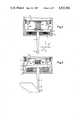
- FIG. 1is a longitudinal section through a first embodiment of a probe head, with its probe element shown in its at-rest position;
- FIG. 2is a similar section to show the probe element of FIG. 1 in a deflected position
- FIG. 3is a longitudinal section through a second probe-head embodiment
- FIG. 4is another sectional view through the embodiment of FIG. 3, along the line IV--IV of FIG. 3;
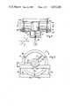
- FIG. 5is a longitudinal sectional through a third probe-head embodiment, the section being on the alignment V--V of FIG. 6;
- FIG. 6is another sectional view through the embodiment of FIG. 5, along the line VI--VI of FIG. 5;
- FIG. 7is a cross-section through a fourth probe-head embodiment which is slightly modified as compared with the embodiment of FIGS. 5 and 6, the section being in a plane perpendicular to the longitudinal axis of the probe element;
- FIG. 8is a perspective view, partly broken-away and in section, to show a fifth embodiment of the invention.
- FIG. 9is an enlarged and more detailed showing of flexible strips used for probe-element suspension in the embodiments of FIGS. 5 to 7.
- the work-contacting probe head in FIGS. 1 and 2comprises a cylindrical housing 1 in which a cylindrical plate 2 mounts a probe element or pin 4, having a work-contacting ball 9 at the projecting end of its stem; plate 2 is suspended from housing 1, on three steel wires 5a-c.
- the steel wireswhich are at 120° spacing on a circle locus concentric with the axis of probe pin 4 (in the at-rest position of FIG. 1) and are tensed by a compression spring 6 referenced at a plate 8 which closes the machine side of housing 1.
- Piezoelectric sensors 7are integrated into the suspension points of the wires 5; they provide an electric-signal output upon a reduction in tension of wires 5a-c, namely, in the course of the probing process (FIG. 2), when probe ball 9 is in contact with the workpiece 10.
- a bellows 3is secured between plate 2, which mounts the probe pin, and that part of the housing 1 which substantially closes the work-contacting side, said bellows being compressed by spring 6 to the extent that the surfaces of the folds of the bellows 3 are close to but not in contact with each other.
- the cushion of air remaining between the surfaces of the foldswill be understood to dampen the movement of the probe element upon return to its at-rest position, which determines the zero point of the probe.
- the probe shown in FIGS. 3 and 4is of a construction similar to that of FIGS. 1 and 2, in that it comprises a housing 11 within which a plate 12 is suspended from three filaments 15a-c.
- the stem 14 of a star-shaped probe-pin combination, having probe balls 19a, b and c,is mounted to and projects from plate 12.
- the plate 12 of FIGS. 3 and 4is not suspended directly from housing 11 but, rather, from an intermediate member 20 which in turn is restrained by three filaments 17a-c.
- Compression springs 16 and 18are referenced to an arm forming part of housing 11 and stress filaments 15 and 17 in tension, to thereby define the zero position of probe balls 19a-c, with respect to the Z direction of displacement, which coincides with the longitudinal axis of the probe.
- the probe-element plate 12 and thus the stem 14 of the probe elementare centered by two balls 13a and 13b in a plane normal to the at-rest longitudinal axis of the probe-pin stem 14 and are retained against torsional displacement about this axis.
- each of the balls 13a and 13bis captive in a cage formed by facing V-shaped grooves in housing 11 and in the plate 12; each of these balls has rolling contact with the walls of its cage, upon a tilting or a Z-displacement of the probe-element plate 12.
- the part 25 of the housing 11 containing the groove for the ball 13ais developed, by reason of slit 24 (as well as a radially limited slit 26), as a lever arm which is flexibly movable about a fulcrum at locally shallow remaining web 22; said arm is inwardly urged by a tension spring 23 in the direction of plate 12, thereby resiliently loading both balls 13a and 13b for rolling contact with their grooves at all times.
- balls 19a-c of the probe elementare movable in all six directions of space, namely, +X, -X; +Y, -Y, +Z, -Z.
- the probe described in FIGS. 1 and 2is movable only in the five directions ⁇ X, ⁇ Y, +Z; however, it will be understood that the probe of FIGS. 1 and 2 can be expanded for probing in -Z direction if the probe pin 4 is suspended indirectly via an intermediate member, as in the manner shown for intermediate member 20 in FIGS. 3 to 4. In the latter event, no direct centering of probe pin 4 with respect to the housing 1 of FIGS.
- the probe element of FIGS. 3 and 4is well suited for horizontal operation, wherein the longitudinal axis of the probe stem 14 lies in the X, Y plane (see axis diagram associated with FIG. 3) since the weight of the probe element can be sustained by balls 13a and 13b, as loaded by spring 23.
- an adjustable tension spring 27applies balancing force between housing 11 and an arm 28 fixed to plate 12.
- FIGS. 5 and 6show another embodiment of a work-contacting probe in which a movable part 32 which mounts a probe pin 34 is not only suspended in the Z-direction of displacement (on flexible strips 35a, b and c which are tensioned by the spring 36) but is also centered by three additional flexible strips 33a, b, c, in a plane normal to the displacement direction and is secured against torsional displacement.
- the flexible strips 33a and 33bare tensioned between two bars 38 and 39; one (38) of these bars is rigidly secured to a cylindrical part 31 fixed to the housing, and the other (39) of these bars is rigidly secured to the movable part 32.
- the bars 38-39separate the points of attachment of strips 33a and 33b as much as possible, so as to widen the base.
- the strip 33cserves for centering in the X-direction; the three strips 33a, b and c are jointly tensioned by a spring 37 which is installed to apply torsion force at an angle to all three of these strips.
- FIGS. 5 and 6can be simplified, with a minor concession as to torsional rigidity if, instead of three centering strips 33a, b and c, two strips 133a and 133b are used in the arrangement sketched in FIG. 7.
- the strips 133a and 133bare inclined to each other, and geometric projections of their respective alignments intersect at a point which is eccentric to the longitudinal axis of the probe head.
- Strips 133a and 113bare tensed by a spring 137, applying tensile force in the direction of the bisector of the angle subtended by the respective alignments of the bands 133a and 133b.
- FIG. 9illustrates, for the case of strip 33c (taken by way of example), that ends of the strips are secured in cylindrical sleeves 134, as by soldering. These sleeves are received in the corresponding boreholes, in that part of the probe which is to be suspended and, after tensioning and twisting to the desired extent, are securely clamped by a screw.
- the angle of twistis about 90°, assurance thus being had that the strips can bend easily in all directions.
- the work-contacting probe of FIG. 8is of particularly simple, symmetrical construction.
- a movable plate 42which mounts a probe pin 44 is suspeneded from a housing part 41, which is provided with a mounting cone 43 at the machine end of the housing.
- Six steel wiresprovide the suspension and are tensed by a central spring 46.
- the steel wiresare arranged in two groups, 45a, b and c and 47a, b and c of three wires each, the groups being skewed in opposite directions about the axis of the probe pin.
- two wires 45a, 47a and 45b, as well as 45c and 47c, from the respective groupswill be understood to cross each other without, however, touching one another. Since the points of connection of wires 45 and 47 to the plate 42 are closer to each other than the points of their connection to the housing part 41, the wires 45 and 47 lie approximately on the surface of a conical frustum.
- the probe of FIG. 8may be made very compact and with small dimensions, without impairing accessibility of all the suspension points of the wires 45 and 47, which may be peripherally accessible via outer surfaces of plate 42 and the closed end of housing part 41.
- the probe of FIG. 8may be modified to incorporate ⁇ Z-direction displacements, using the technique described in connection with FIGS. 3 and 4, namely, by supporting the probe pin 44 indirectly via an intermediate member, thereby rendering the probe movable in all six directions in space.
- the intermediate membercan be suspended from the housing via six wires which cross each other in pairs, and the probe-element plate 42 can similarly be suspended from the intermediate member via six further wires which cross each other in pairs.
- the probe head of FIG. 8 as well as the embodiments of FIGS. 3 to 7desirably include sensors which provide a characteristic output signal upon probe-ball contact with a workpiece.
- piezoelectric elementsmay be employed as described in FIGS. 1 and 2, such elements being arranged at the suspension points of the wires or strips, or they may be integrated at a suitable place into the movable pin-mounting part of the probe head. Such arrangements are known, for example, from West German Pat. No. 2,712,181.
Landscapes
- Physics & Mathematics (AREA)
- General Physics & Mathematics (AREA)
- A Measuring Device Byusing Mechanical Method (AREA)
- Length Measuring Devices With Unspecified Measuring Means (AREA)
- Measurement Of Length, Angles, Or The Like Using Electric Or Magnetic Means (AREA)
Abstract
Description
Claims (20)
Applications Claiming Priority (2)
| Application Number | Priority Date | Filing Date | Title |
|---|---|---|---|
| DE19823215878DE3215878A1 (en) | 1982-04-29 | 1982-04-29 | PROBE HEAD FOR COORDINATE MEASURING DEVICES |
| DE3215878 | 1982-04-29 |
Publications (1)
| Publication Number | Publication Date |
|---|---|
| US4523382Atrue US4523382A (en) | 1985-06-18 |
Family
ID=6162189
Family Applications (1)
| Application Number | Title | Priority Date | Filing Date |
|---|---|---|---|
| US06/480,822Expired - Fee RelatedUS4523382A (en) | 1982-04-29 | 1983-03-31 | Work-contact probe head for coordinate-measuring instruments |
Country Status (4)
| Country | Link |
|---|---|
| US (1) | US4523382A (en) |
| EP (1) | EP0093299B1 (en) |
| JP (1) | JPS58196401A (en) |
| DE (2) | DE3215878A1 (en) |
Cited By (31)
| Publication number | Priority date | Publication date | Assignee | Title |
|---|---|---|---|---|
| US4660296A (en)* | 1984-04-03 | 1987-04-28 | Mauser-Werke Oberndorf Gmbh | Sensing head for a measuring machine |
| US4752166A (en)* | 1987-01-02 | 1988-06-21 | Manuflex Corp. | Probing device |
| US4778313A (en)* | 1987-05-18 | 1988-10-18 | Manuflex Corp. | Intelligent tool system |
| US4879916A (en)* | 1987-06-29 | 1989-11-14 | Meseltron S.A. | Contact sensor for calipering pieces such as workpieces |
| US5074052A (en)* | 1986-12-09 | 1991-12-24 | Renishaw Plc | Contact-sensing probe |
| US5111592A (en)* | 1991-07-12 | 1992-05-12 | Carl-Zeiss-Stiftung, Heidenheim/Brenz | Probe head of the switching type |
| US5209131A (en)* | 1989-11-03 | 1993-05-11 | Rank Taylor Hobson | Metrology |
| US5212873A (en)* | 1990-01-25 | 1993-05-25 | Renishaw Plc | Position-sensing probe |
| US5222304A (en)* | 1988-07-05 | 1993-06-29 | British Technology Group Limited | Probes |
| US5276976A (en)* | 1992-09-15 | 1994-01-11 | Hawkes Hollis D | Indicator tip turret |
| US5299360A (en)* | 1990-03-06 | 1994-04-05 | Marposs Societa' Per Azioni | Probe for checking linear dimensions |
| US5322007A (en)* | 1991-08-15 | 1994-06-21 | Heat And Control, Inc. | Compact, high-capacity oven |
| US5323540A (en)* | 1990-02-23 | 1994-06-28 | Renishaw Metrology Ltd. | Touch probe |
| US5353514A (en)* | 1990-02-23 | 1994-10-11 | Renishaw, Plc | Touch probe |
| US5390424A (en)* | 1990-01-25 | 1995-02-21 | Renishaw Metrology Limited | Analogue probe |
| US5390423A (en)* | 1991-01-22 | 1995-02-21 | Renishaw Plc | Analogue probe |
| US5491904A (en)* | 1990-02-23 | 1996-02-20 | Mcmurtry; David R. | Touch probe |
| US5505005A (en)* | 1990-02-23 | 1996-04-09 | Renishaw Plc | Touch probe |
| US5712961A (en)* | 1995-09-19 | 1998-01-27 | Minolta Co., Ltd. | Contact-type sensor |
| US20050150125A1 (en)* | 2002-04-05 | 2005-07-14 | Renishaw Plc | Kinematic coupling with damper |
| US20060096396A1 (en)* | 2004-11-09 | 2006-05-11 | Perkinelmer Las, Inc. | Methods and systems for determining a position of a probe |
| US20060271420A1 (en)* | 2005-05-27 | 2006-11-30 | Peter Anselmann | System and method for performing capacity checks and resource scheduling within a supply chain management system |
| US7259552B2 (en) | 2002-05-31 | 2007-08-21 | Siemens Power Generation, Inc. | Wear monitor for turbo-machine |
| US20070283762A1 (en)* | 2006-03-28 | 2007-12-13 | Thomas Schroll | Probe |
| US20090100693A1 (en)* | 2006-05-08 | 2009-04-23 | Renishaw Plc | Contact Sensing Probe |
| US20090300929A1 (en)* | 2006-05-08 | 2009-12-10 | Taylor Hobson Limited | Metrological apparatus for measuring surface characteristics |
| CN104246422A (en)* | 2012-04-24 | 2014-12-24 | 赫克斯冈技术中心 | Sensor element for a measuring machine, in particular a coordinate measuring machine |
| CN104406614A (en)* | 2014-12-01 | 2015-03-11 | 哈尔滨同和光学精密机械有限公司 | Autorotation measuring head seat with three-dimensional anticollision function for gear measuring center |
| US20180245906A1 (en)* | 2015-09-15 | 2018-08-30 | Micro-Epsilon Messtechnik Gmbh & Co. Kg | Device and sensor for contactless distance and/or position determination of a measurement |
| US11709045B1 (en)* | 2022-02-19 | 2023-07-25 | National Institute Of Metrology, China | Surface texture probe and measurement apparatus with a vibrational membrane |
| CN118816787A (en)* | 2024-09-19 | 2024-10-22 | 山东艾克赛尔机械制造有限公司 | A trailer axle measuring device |
Families Citing this family (4)
| Publication number | Priority date | Publication date | Assignee | Title |
|---|---|---|---|---|
| FR2569474B1 (en)* | 1984-08-27 | 1986-12-26 | Meseltron Sa | DEVICE FOR MEASURING THE AXIAL POSITION OF A WORKPIECE, PARTICULARLY ON A MACHINE FOR GRINDING EXTERNAL CYLINDRICAL SURFACES |
| DE3506892A1 (en)* | 1985-02-27 | 1986-09-04 | Fa. Carl Zeiss, 7920 Heidenheim | Probe for coordinate measuring machines |
| DE3830806A1 (en)* | 1988-09-09 | 1990-03-22 | Maho Ag | SENSORS FOR SCANING SURFACES |
| DE4300026A1 (en)* | 1993-01-02 | 1994-07-07 | Andreas Lotze | Sensing head for coordinate measurement device |
Citations (4)
| Publication number | Priority date | Publication date | Assignee | Title |
|---|---|---|---|---|
| US2858071A (en)* | 1956-01-16 | 1958-10-28 | Stokes John Arthur | Arrangement for computing the total deflection of a stylus |
| US4136458A (en)* | 1976-10-01 | 1979-01-30 | The Bendix Corporation | Bi-axial probe |
| US4177568A (en)* | 1977-03-19 | 1979-12-11 | Carl Zeiss-Stiftung | Measurement head |
| US4397093A (en)* | 1976-12-24 | 1983-08-09 | Rolls Royce Limited | Probe for use in measuring apparatus |
Family Cites Families (4)
| Publication number | Priority date | Publication date | Assignee | Title |
|---|---|---|---|---|
| CH498371A (en)* | 1967-08-09 | 1970-10-31 | D Assortiments Reunies Succurs | Device for transmitting the polar movement of a probe |
| GB1445977A (en)* | 1972-09-21 | 1976-08-11 | Rolls Royce | Probes |
| CH596538A5 (en)* | 1976-02-12 | 1978-03-15 | Maag Zahnraeder & Maschinen Ag | |
| JPS56168101A (en)* | 1980-05-28 | 1981-12-24 | Mitsubishi Electric Corp | Tracer head |
- 1982
- 1982-04-29DEDE19823215878patent/DE3215878A1/ennot_activeWithdrawn
- 1983
- 1983-03-31USUS06/480,822patent/US4523382A/ennot_activeExpired - Fee Related
- 1983-04-16DEDE8383103708Tpatent/DE3361472D1/ennot_activeExpired
- 1983-04-16EPEP83103708Apatent/EP0093299B1/ennot_activeExpired
- 1983-04-25JPJP58071573Apatent/JPS58196401A/enactivePending
Patent Citations (5)
| Publication number | Priority date | Publication date | Assignee | Title |
|---|---|---|---|---|
| US2858071A (en)* | 1956-01-16 | 1958-10-28 | Stokes John Arthur | Arrangement for computing the total deflection of a stylus |
| US4136458A (en)* | 1976-10-01 | 1979-01-30 | The Bendix Corporation | Bi-axial probe |
| US4136458B1 (en)* | 1976-10-01 | 1989-07-04 | Renishaw Plc | |
| US4397093A (en)* | 1976-12-24 | 1983-08-09 | Rolls Royce Limited | Probe for use in measuring apparatus |
| US4177568A (en)* | 1977-03-19 | 1979-12-11 | Carl Zeiss-Stiftung | Measurement head |
Cited By (39)
| Publication number | Priority date | Publication date | Assignee | Title |
|---|---|---|---|---|
| US4660296A (en)* | 1984-04-03 | 1987-04-28 | Mauser-Werke Oberndorf Gmbh | Sensing head for a measuring machine |
| US5074052A (en)* | 1986-12-09 | 1991-12-24 | Renishaw Plc | Contact-sensing probe |
| US4752166A (en)* | 1987-01-02 | 1988-06-21 | Manuflex Corp. | Probing device |
| US4778313A (en)* | 1987-05-18 | 1988-10-18 | Manuflex Corp. | Intelligent tool system |
| US4879916A (en)* | 1987-06-29 | 1989-11-14 | Meseltron S.A. | Contact sensor for calipering pieces such as workpieces |
| US5222304A (en)* | 1988-07-05 | 1993-06-29 | British Technology Group Limited | Probes |
| US5209131A (en)* | 1989-11-03 | 1993-05-11 | Rank Taylor Hobson | Metrology |
| US5212873A (en)* | 1990-01-25 | 1993-05-25 | Renishaw Plc | Position-sensing probe |
| US5390424A (en)* | 1990-01-25 | 1995-02-21 | Renishaw Metrology Limited | Analogue probe |
| US5323540A (en)* | 1990-02-23 | 1994-06-28 | Renishaw Metrology Ltd. | Touch probe |
| US5339535A (en)* | 1990-02-23 | 1994-08-23 | Renishaw Metrology Limited | Touch probe |
| US5353514A (en)* | 1990-02-23 | 1994-10-11 | Renishaw, Plc | Touch probe |
| US5669152A (en)* | 1990-02-23 | 1997-09-23 | Renishaw, Plc | Touch probe |
| US5491904A (en)* | 1990-02-23 | 1996-02-20 | Mcmurtry; David R. | Touch probe |
| US5505005A (en)* | 1990-02-23 | 1996-04-09 | Renishaw Plc | Touch probe |
| US5299360A (en)* | 1990-03-06 | 1994-04-05 | Marposs Societa' Per Azioni | Probe for checking linear dimensions |
| US5390423A (en)* | 1991-01-22 | 1995-02-21 | Renishaw Plc | Analogue probe |
| US5111592A (en)* | 1991-07-12 | 1992-05-12 | Carl-Zeiss-Stiftung, Heidenheim/Brenz | Probe head of the switching type |
| US5322007A (en)* | 1991-08-15 | 1994-06-21 | Heat And Control, Inc. | Compact, high-capacity oven |
| US5276976A (en)* | 1992-09-15 | 1994-01-11 | Hawkes Hollis D | Indicator tip turret |
| US5712961A (en)* | 1995-09-19 | 1998-01-27 | Minolta Co., Ltd. | Contact-type sensor |
| US20050150125A1 (en)* | 2002-04-05 | 2005-07-14 | Renishaw Plc | Kinematic coupling with damper |
| US7055258B2 (en)* | 2002-04-05 | 2006-06-06 | Renishaw Plc | Kinematic coupling with damper |
| US7259552B2 (en) | 2002-05-31 | 2007-08-21 | Siemens Power Generation, Inc. | Wear monitor for turbo-machine |
| US7353688B2 (en)* | 2004-11-09 | 2008-04-08 | Perkinelmer Las, Inc. | Methods and systems for determining a position of a probe |
| US20060096396A1 (en)* | 2004-11-09 | 2006-05-11 | Perkinelmer Las, Inc. | Methods and systems for determining a position of a probe |
| US20060271420A1 (en)* | 2005-05-27 | 2006-11-30 | Peter Anselmann | System and method for performing capacity checks and resource scheduling within a supply chain management system |
| US7516672B2 (en)* | 2006-03-28 | 2009-04-14 | Dr. Johannes Heidenhain Gmbh | Probe including pressure sensitive sensors |
| US20070283762A1 (en)* | 2006-03-28 | 2007-12-13 | Thomas Schroll | Probe |
| US20090100693A1 (en)* | 2006-05-08 | 2009-04-23 | Renishaw Plc | Contact Sensing Probe |
| US20090300929A1 (en)* | 2006-05-08 | 2009-12-10 | Taylor Hobson Limited | Metrological apparatus for measuring surface characteristics |
| US7856731B2 (en) | 2006-05-08 | 2010-12-28 | Renishaw Plc | Contact sensing probe |
| US8051576B2 (en) | 2006-05-08 | 2011-11-08 | Taylor Hobson Limited | Metrological apparatus for measuring surface characteristics |
| CN104246422A (en)* | 2012-04-24 | 2014-12-24 | 赫克斯冈技术中心 | Sensor element for a measuring machine, in particular a coordinate measuring machine |
| US9459091B2 (en) | 2012-04-24 | 2016-10-04 | Hexagon Technology Center Gmbh | Sensor element for a measuring machine, in particular a coordinate measuring machine |
| CN104406614A (en)* | 2014-12-01 | 2015-03-11 | 哈尔滨同和光学精密机械有限公司 | Autorotation measuring head seat with three-dimensional anticollision function for gear measuring center |
| US20180245906A1 (en)* | 2015-09-15 | 2018-08-30 | Micro-Epsilon Messtechnik Gmbh & Co. Kg | Device and sensor for contactless distance and/or position determination of a measurement |
| US11709045B1 (en)* | 2022-02-19 | 2023-07-25 | National Institute Of Metrology, China | Surface texture probe and measurement apparatus with a vibrational membrane |
| CN118816787A (en)* | 2024-09-19 | 2024-10-22 | 山东艾克赛尔机械制造有限公司 | A trailer axle measuring device |
Also Published As
| Publication number | Publication date |
|---|---|
| JPS58196401A (en) | 1983-11-15 |
| DE3215878A1 (en) | 1983-11-03 |
| DE3361472D1 (en) | 1986-01-23 |
| EP0093299B1 (en) | 1985-12-11 |
| EP0093299A1 (en) | 1983-11-09 |
Similar Documents
| Publication | Publication Date | Title |
|---|---|---|
| US4523382A (en) | Work-contact probe head for coordinate-measuring instruments | |
| US5353514A (en) | Touch probe | |
| US6683780B2 (en) | Capacitive displacement sensor | |
| US5491904A (en) | Touch probe | |
| JPS62501234A (en) | Touch-sensing probe | |
| CN101142461A (en) | Measurement probe | |
| WO1990012998A1 (en) | Position determining apparatus | |
| US12287194B2 (en) | Motion mechanism for measuring probe | |
| US20250130032A1 (en) | A scanning probe | |
| US6886265B2 (en) | Touch probing device | |
| US7392596B2 (en) | Probe head | |
| JPH0575337B2 (en) | ||
| JP7163886B2 (en) | measuring device | |
| JPS6322526B2 (en) | ||
| US4977775A (en) | Torque transducer | |
| KR100806831B1 (en) | Multi-coordinate detection measuring device | |
| TW513554B (en) | Multi-coordinate probe measurement appliance | |
| US3906788A (en) | Self-supporting strain transducer | |
| JP2000258332A (en) | Cantilever for detecting normal force for atomic force microscope | |
| EP0355079A1 (en) | Fastening implement | |
| CN110095050A (en) | A kind of triangular beam flexible constraint variation rigidity micro-nano gauge head | |
| CN120489033B (en) | Contact type machine tool measuring head and measuring equipment | |
| JPS58221146A (en) | Attaching structure of test piece | |
| JPH074488Y2 (en) | Contact detection device | |
| JPH06190639A (en) | Attitude adjusting device for object |
Legal Events
| Date | Code | Title | Description |
|---|---|---|---|
| AS | Assignment | Owner name:CARL ZEISS-STIFTUNG, D/B/U/FIRM ZEISS, CARL, 7082 Free format text:ASSIGNMENT OF ASSIGNORS INTEREST.;ASSIGNORS:WERNER, WALTER;HERZOG, KLAUS;SZENGER, FRANZ;REEL/FRAME:004131/0306 Effective date:19830325 Owner name:CARL ZEISS-STIFTUNG, D/B/U/FIRM ZEISS, CARL, 7082 Free format text:ASSIGNMENT OF ASSIGNORS INTEREST;ASSIGNORS:WERNER, WALTER;HERZOG, KLAUS;SZENGER, FRANZ;REEL/FRAME:004131/0306 Effective date:19830325 | |
| AS | Assignment | Owner name:CARL-ZEISS-STIFTUNG, HEIDENHEIM/BRENZ, DBA CARL ZE Free format text:STATEMENT BY ASSIGNEE TO CORRECT THE ADDRESSES OF PREVIOUSLY RECORDED ASSIGNMENTS;ASSIGNOR:CARL-ZEISS-STIFTUNG, DBA CARL ZEISS;REEL/FRAME:004219/0893 Effective date:19840110 | |
| FEPP | Fee payment procedure | Free format text:PAYOR NUMBER ASSIGNED (ORIGINAL EVENT CODE: ASPN); ENTITY STATUS OF PATENT OWNER: LARGE ENTITY | |
| FPAY | Fee payment | Year of fee payment:4 | |
| FPAY | Fee payment | Year of fee payment:8 | |
| REMI | Maintenance fee reminder mailed | ||
| LAPS | Lapse for failure to pay maintenance fees | ||
| FP | Lapsed due to failure to pay maintenance fee | Effective date:19970518 | |
| STCH | Information on status: patent discontinuation | Free format text:PATENT EXPIRED DUE TO NONPAYMENT OF MAINTENANCE FEES UNDER 37 CFR 1.362 |