US4522270A - Hand-held electric tool - Google Patents
Hand-held electric toolDownload PDFInfo
- Publication number
- US4522270A US4522270AUS06/509,773US50977383AUS4522270AUS 4522270 AUS4522270 AUS 4522270AUS 50977383 AUS50977383 AUS 50977383AUS 4522270 AUS4522270 AUS 4522270A
- Authority
- US
- United States
- Prior art keywords
- housing
- grip
- longitudinal axis
- pivot
- tool
- Prior art date
- Legal status (The legal status is an assumption and is not a legal conclusion. Google has not performed a legal analysis and makes no representation as to the accuracy of the status listed.)
- Expired - Lifetime
Links
Images


Classifications
- B—PERFORMING OPERATIONS; TRANSPORTING
- B23—MACHINE TOOLS; METAL-WORKING NOT OTHERWISE PROVIDED FOR
- B23B—TURNING; BORING
- B23B45/00—Hand-held or like portable drilling machines, e.g. drill guns; Equipment therefor
- B23B45/001—Housing of the drill, e.g. handgrip
- B—PERFORMING OPERATIONS; TRANSPORTING
- B23—MACHINE TOOLS; METAL-WORKING NOT OTHERWISE PROVIDED FOR
- B23B—TURNING; BORING
- B23B45/00—Hand-held or like portable drilling machines, e.g. drill guns; Equipment therefor
- B23B45/008—Gear boxes, clutches, bearings, feeding mechanisms or like equipment
- B—PERFORMING OPERATIONS; TRANSPORTING
- B23—MACHINE TOOLS; METAL-WORKING NOT OTHERWISE PROVIDED FOR
- B23B—TURNING; BORING
- B23B45/00—Hand-held or like portable drilling machines, e.g. drill guns; Equipment therefor
- B23B45/02—Hand-held or like portable drilling machines, e.g. drill guns; Equipment therefor driven by electric power
- Y—GENERAL TAGGING OF NEW TECHNOLOGICAL DEVELOPMENTS; GENERAL TAGGING OF CROSS-SECTIONAL TECHNOLOGIES SPANNING OVER SEVERAL SECTIONS OF THE IPC; TECHNICAL SUBJECTS COVERED BY FORMER USPC CROSS-REFERENCE ART COLLECTIONS [XRACs] AND DIGESTS
- Y10—TECHNICAL SUBJECTS COVERED BY FORMER USPC
- Y10T—TECHNICAL SUBJECTS COVERED BY FORMER US CLASSIFICATION
- Y10T408/00—Cutting by use of rotating axially moving tool
- Y10T408/65—Means to drive tool
- Y—GENERAL TAGGING OF NEW TECHNOLOGICAL DEVELOPMENTS; GENERAL TAGGING OF CROSS-SECTIONAL TECHNOLOGIES SPANNING OVER SEVERAL SECTIONS OF THE IPC; TECHNICAL SUBJECTS COVERED BY FORMER USPC CROSS-REFERENCE ART COLLECTIONS [XRACs] AND DIGESTS
- Y10—TECHNICAL SUBJECTS COVERED BY FORMER USPC
- Y10T—TECHNICAL SUBJECTS COVERED BY FORMER US CLASSIFICATION
- Y10T74/00—Machine element or mechanism
- Y10T74/19—Gearing
- Y10T74/19642—Directly cooperating gears
- Y10T74/19679—Spur
- Y10T74/19684—Motor and gearing
- Y—GENERAL TAGGING OF NEW TECHNOLOGICAL DEVELOPMENTS; GENERAL TAGGING OF CROSS-SECTIONAL TECHNOLOGIES SPANNING OVER SEVERAL SECTIONS OF THE IPC; TECHNICAL SUBJECTS COVERED BY FORMER USPC CROSS-REFERENCE ART COLLECTIONS [XRACs] AND DIGESTS
- Y10—TECHNICAL SUBJECTS COVERED BY FORMER USPC
- Y10T—TECHNICAL SUBJECTS COVERED BY FORMER US CLASSIFICATION
- Y10T74/00—Machine element or mechanism
- Y10T74/20—Control lever and linkage systems
- Y10T74/20576—Elements
- Y10T74/20732—Handles
Definitions
- This inventionis directed to a hand-held electric tool, more particularly to a hand-held tool for fastening and drilling operations by the use of a corresponding bit attached thereto and rotatably driven by an incorporated electric motor.
- the above disadvantages of the prior hand-held electric toolsare obviated by the present invention which provides a novel and improved construction of a hand-held electric tool, allowing an operator to handle the tool in two different operating positions depending upon the available space.
- the electric tool in accordance with the present inventioncomprises an elongated housing having a first longitudinal axis and provided with a motor-driven chuck projecting from the forward end thereof, and an elongated grip having a second longitudinal axis, the grip being pivotally connected at its forward end to the rear end of the housing so as to permit the operator to selectively assume a straight position where the first longitudinal axis is in line with the second longitudinal axis or an angled position where the two axes are crossed.
- This featureenables the tool to be manipulated by the operator to form the straight construction or the angled construction in order to be brought into a proper and easy handling position for use at different working locations and against workpieces. Also with this feature, the tool can be arranged or packed within a relatively small space as in a toolbox and the like by selecting the straight or angled position depending upon the size and shape of storage space.
- a useful structurein which the grip is pivotally connected to the housing so as to effectuate easy and prompt conversion between the above two positions, and the motor is mounted in the housing while an electric battery to be electrically connected thereto is mounted in the grip in order to properly balance the tool for one-hand operation.
- the present inventionpreferably has a retractable cover which telescopes over the grip when moving from the angled position to the straight position to cover the gap formed between the confronting ends of the housing and the grip when in the straight position, preventing the fingers of the operator from being inadvertently nipped in the gap and providing a smooth fit between the tool and the hand grasping it.
- the retractable coverhas means for retaining the grip in both straight and angled positions to prevent its movement unless a force is applied to shift the position of the grip.
- Another object of the present inventionis to provide an electric tool capable of being readily and promptly shifted between two operating positions.
- Still another object of the present inventionis to provide a properly balanced tool which is easily manipulated with one hand.
- a further object of the present inventionis to provide an electric tool which eliminates accidental nipping of the fingers grasping the tool and thereby assuring a comfortable grip.
- Another object of the present inventionis to provide an electric tool which is free from movement of the grip in relation to the housing so as to ensure stable operation.
- FIG. 1is a perspective view showing a hand-held electric tool with the grip arranged in the angled position in accordance with the present invention
- FIG. 2is a perspective view showing the tool with the grip extended in the straight position
- FIG. 3is a side view showing a partial cross-section of the electric tool
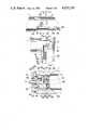
- FIG. 4is an exploded perspective view showing the parts interconnecting the housing and the grip of the tool
- FIG. 5is a transverse sectional view taken along a line substantially corresponding to the line X--X in FIG. 3;
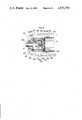
- FIGS. 6a and 6bare enlarged longitudinal sectional views showing the portion interconnecting the housing and the grip respectively in its straight position and angled position;
- FIG. 7is a fragmentary enlarged longitudinal section showing the interior construction of the speed reduction means employed in the electric tool in which a torque limiting clutch is engaged;
- FIG. 8is an exploded perspective view showing the parts of the above speed reduction means
- FIG. 9is a perspective view of the internal gear composing the above speed reduction means.
- FIG. 10ais an exploded fragmentary perspective view showing a part of the retainer ring composing the speed reduction means and the ball to be retained thereby;
- FIG. 10bis a fragmentary sectional view of the above retainer ring and the ball seated therein;
- FIG. 11is a fragmentary perspective view showing parts of the speed reduction means half assembled with the retainer ring kept in position by the sleeve;
- FIG. 12is a fragmentary enlarged longitudinal section showing the interior construction of the speed reduction means in which the torque limiting clutch is disengaged.
- a hand-held electric screwdriveras a preferred embodiment of the present invention, including an elongated cylindrical housing 1 having a first longitudinal axis and an elongated cylindrical grip 2 having a second longitudinal axis and pivotally connected at its forward end to the rearward end of the housing 1.
- an electric motor 5 and speed reduction meanswithin the housing 1 are mounted an electric motor 5 and speed reduction means, the details of which will be hereinafter explained.
- a chuck 4 for holding a screwdriver bitprojects coaxially from the forward end of the housing 1 and is operatively connected to the motor 5 so as to be rotatably driven thereby.
- the housing 1also carries an electric slide switch 6 for electrically connecting and disconnecting the motor 5 to and from an electric battery 7 disposed within the grip 2.
- the battery 7consists of a series of rechargeable battery cells and is supplied with electricity, when required, through a pair of terminals 8 at the rear of the grip 2, which are adapted to be detachable connected to a battery charger (not shown).
- Both housing 1 and grip 2are made of synthetic resin and have approximately equal diameter and length.
- the housing 1is constructed of a pair of two halves 1a, each of which has one part of a pair of cooperating projections 10 at its rear end, such projections being held together to form a pivot tang 11.
- the grip 2is also constructed of a pair of halves 2a, each having at its forward upper side a yoke 20 projecting longitudinally to define at the forward lower side thereof a recessed portion 21.
- a yoke 20projecting longitudinally to define at the forward lower side thereof a recessed portion 21.
- Formed integrally with one of the yokes 20is a hollow post 22 projecting inwardly thereof and in a direction perpendicular to said second longitudinal axis.
- Each projection 10, forming the pivot tang 11has an inwardly projecting hub 12, with a bore 13 extending therethrough.
- hubs 12are combined when two halves 1a are held together to form a pivot bearing, through which said hollow post 22 extends to pivotally connect grip 2 to housing 1, and grip 2 is permitted to pivot in a plane including said first and second longitudinal axes about the hollow post 22, which defines a pivot axis.
- a screw 23engages threadedly into the hollow post 22 to unite the two halves 2a into the grip 2, while retaining the hollow post 22 in rotatable engagement within said pivot bearing, as well as overlapping the pivot tang 11 with the yokes 20.
- first and second stops 24 and 25are circumferentially spaced apart along a circle having the coincident center with with hollow post 22, so that the grip 2 can be rotated relative to the housing 1 in one direction until the first stop 24 abuts against a first seat 14 on the upper rearward end of the housing 1 to assume a straight position, where said first and second longitudinal axes are in line with each other and that the grip 2 can be rotated in the opposite direction until the second stop 25 abuts against the second seat 15 on the lower rearward end of the housing 1 to assume an angled position, where said first and second longitudinal axes cross one another at approximately right angles.
- the grip 2is limited to swing about the pivot axis relative to the housing 1 between such straight and angled positions.
- a retractable cover 3Disposed between the lower rearward end of the housing 1 and the lower forward end of the grip 2 is a retractable cover 3, which telescopes internally of the grip 2, that is, the cover 3 is to be disposed on the side which will constitute the inside of the corner formed by the housing 1 and the grip 2 when in said angled position.
- the retractable cover 3has at its forward end a pair of outwardly projecting pins 30, which are slidably and pivotally received within the corresponding grooves 18, respectively formed on the interior of the halves 1a and elongated along an oblique axis inclined at approximately 45 degrees to said first longitudinal axis.
- the rear portion of the retractable cover 3is slidably received within a longitudinally and circumferentially elongated channel 26, provided within the lower forward portion of the grip 2, with its open end exposed adjacent said recessed portion 21. Accordingly, as shown in FIG. 6a, the cover 3 will extend from the channel 26 to close a gap between the lower portions of the housing 1 and the grip 2 when the tool is extended in said straight position, such gap being largely defined by said recessed portion formed at the lower forward end of the grip 2. As the grip 2 is moved from the straight position to the angled position, the cover 3 will gradually retract into the channel 26 and be received within the grip 2 when the grip 2 is in the angled position, as shown in FIG. 6b. In the straight position, as shown in FIG.
- the upper lateral edge of the cover 3abuts intermediate its longitudinal ends against a rib 16, projecting radially from said hub 12 so as to prevent the accidental inward movement of the cover 3 due to the external force which may be applied thereto by the finger of an operator grasping the tool. Also, in this position, the lower extremity of the forward end of the grip 2 snaps into the cutout 32 formed at the outer rear end of the cover 3 to retain the cover 3 in position, which in turn prevents inadvertent swinging or rotating movement from the angled position of the grip 2 relative to the housing 1.
- the cover 3is further provided with a hook 34, projecting upwardly from the rear end thereof, which snappedly engages with a node 28 projecting inwardly of the rear portion of the channel 26 when the grip 2 is in the angled position, as seen in FIG. 6b, such that the cover 3 locks the grip 2 to likewise prevent inadvertent and unnecessary swinging movement thereof from this position.
- the cover 3acts not only to prevent the fingers of the operator from accidentally being nipped when the tool is in the straight position, but also to restrict inadvertent movement of the grip 2 to retain it both in the straight and the angled positions.
- FIGS. 7-12there is shown the detailed structure of said speed reduction means which, composed of a double planetary gear train and a torque limiting clutch for protecting the motor 5 against overload, provides a driving connection between the motor 5 and the drive spindle 9 carrying the chuck 4.
- the double planetary gear trainincludes a first sun gear 41 fixed on the output shaft 40 of the motor 5, a coaxial internal gear 42 which is axially slidable, a set of circumferentially spaced first planet gears 43 supported on a first planet carrier 44, a second sun gear 45 formed centrally of and integrally with the first planet carrier 44, a set of circumferentially spaced second planet gears 46 intermeshing with the gears 45 and said internal gear 42 and supported on a second planet carrier 47, from the center of which forwardly projects said drive spindle 9 which is rotatably journaled in the bearing received in a concentric hub 48 projecting forwardly from the gear casing 49, fixedly and coaxially mounted within the housing 1 forwardly of the motor 5.
- an intermediate ring 50Disposed on the hub 48 is an intermediate ring 50, which is axially slidable and rotatively fixed with respect to the gear casing 49 and which threadedly engages with a torque adjusting ring 51 rotatably attached to the front end of the housing 1.
- a set of circumferentially spaced apart pins 52which extend through the front face of the gear casing 49, with their respective front ends abutting against the rear end of the intermediate ring 50 and their respective rear ends abutting through a washer 53 against the front end of the internal gear 42, so as to convert the rotational movement of the torque adjusting ring 51 into the longitudinal or axial movement of the internal gear 42.
- said internal gear 42has, on its rear end, a plurality of axially projecting teeth 54, which are angularly spaced about the axis of the internal gear 42.
- the internal gear 42 with these teeth 54is connected by means of a series of circumferentially spaced balls 55 to a clutch plate 57, which is rotatably and slidably mounted on a boss 61, coaxially projecting from a base 60 secured to the front end of the motor 5.
- the balls 55are seated respectively in the circumferentially spaced sockets 63, formed in a retainer ring 56 located between the internal gear 42 and the clutch plate 57, such balls 55 cooperating with said teeth 54 on the internal gear 42 to provide the torque-limiting clutch.
- the clutch plate 57is biased against the internal gear 42 by means of compression springs 59, which are seated at their respective rear ends in the holes 62 formed in the base 60 and engage at their respective front ends with a washer ring 58, which is rotatively fixed and slidably mounted on the boss 61 so as to be arranged in frictional engagement with the clutch plate 57.
- the compression force exerted by the springs 59tends to keep the balls 55 in engagement with the teeth 54, so as to arrest or lock the internal gear 42 in non-rotatory position, wherein the output shaft 40 of the motor 5 drives the first and second planet gears 43 and 46 to revolve along the stationary internal gear 42 in order to rotate the drive spindle 9 about its axis, whereby the drive torque of the output shaft 40 is transmitted to the drive spindle 9 via the double planetary gear train.
- the torque load on the internal gear 42during the driving operation of the tool, such as for tightening the screw, reaches a predetermined magnitude which is determined by the load on the springs 59, the teeth 54 of the internal gear 42 thrusts the balls 55 rearward, as shown in FIG.
- the magnitude of torque at which the teeth 54 roll over the balls 55 to permit the rotational movement of the internal gear 42is adjusted by varying the compression load on the springs 59.
- This adjustmentis effected by turning said torque adjusting ring 51 at the front end of the housing 1, that is, turning the ring 51 moves said intermediate ring 50 axially, which in turn, moves the internal gear 42 axially by use of the pins 52 and the washer 53 to vary the tension load on the springs 59.
- Each socket 63 for retaining the ball 55is shaped in the form of a tapered bore having at the front face of the retainer ring 56 a smaller opening with a diameter slightly smaller than that of the ball 55, so that the balls 55 can be retained in and thus prevented from springing out of the respective sockets 63 when the parts are half assembled, as shown in FIG. 11, wherein a stop member 64 is pressed fixedly into the base 60 with its flange resting on the inner periphery of the front face of the retainer ring 56.
Landscapes
- Engineering & Computer Science (AREA)
- Mechanical Engineering (AREA)
- Drilling And Boring (AREA)
- Details Of Spanners, Wrenches, And Screw Drivers And Accessories (AREA)
- Percussive Tools And Related Accessories (AREA)
Abstract
Description
1. Field of the Invention
This invention is directed to a hand-held electric tool, more particularly to a hand-held tool for fastening and drilling operations by the use of a corresponding bit attached thereto and rotatably driven by an incorporated electric motor.
2. Description of the Prior Art
There has been provided electric tools of this type, as disclosed in U.S. Pat. Nos. 2,789,597 and 3,687,179 comprising a single housing in which an electric motor rotatably drives a suitable bit locked in a chuck. These tools are utilized by grasping the housing to perform an intended driving operation. However, these tools with a single housing are of a relatively bulky mass to be grasped by the hand of an operator and are sometimes inconvenient to use because the housing itself constitutes a hindrance when the driving operation needs to be performed in a limited space.
The above disadvantages of the prior hand-held electric tools are obviated by the present invention which provides a novel and improved construction of a hand-held electric tool, allowing an operator to handle the tool in two different operating positions depending upon the available space. The electric tool in accordance with the present invention comprises an elongated housing having a first longitudinal axis and provided with a motor-driven chuck projecting from the forward end thereof, and an elongated grip having a second longitudinal axis, the grip being pivotally connected at its forward end to the rear end of the housing so as to permit the operator to selectively assume a straight position where the first longitudinal axis is in line with the second longitudinal axis or an angled position where the two axes are crossed. This feature enables the tool to be manipulated by the operator to form the straight construction or the angled construction in order to be brought into a proper and easy handling position for use at different working locations and against workpieces. Also with this feature, the tool can be arranged or packed within a relatively small space as in a toolbox and the like by selecting the straight or angled position depending upon the size and shape of storage space.
In a preferred embodiment of the present invention, there is disclosed a useful structure in which the grip is pivotally connected to the housing so as to effectuate easy and prompt conversion between the above two positions, and the motor is mounted in the housing while an electric battery to be electrically connected thereto is mounted in the grip in order to properly balance the tool for one-hand operation.
The present invention preferably has a retractable cover which telescopes over the grip when moving from the angled position to the straight position to cover the gap formed between the confronting ends of the housing and the grip when in the straight position, preventing the fingers of the operator from being inadvertently nipped in the gap and providing a smooth fit between the tool and the hand grasping it. Besides the above, the retractable cover has means for retaining the grip in both straight and angled positions to prevent its movement unless a force is applied to shift the position of the grip.
Accordingly, it is a primary object of the present invention to provide a hand-held electric tool which is easy to use and efficient in operation, as well as is easily arranged and stored within a relatively small space with the housing and grip aligned or crossed with respect to each other.
Another object of the present invention is to provide an electric tool capable of being readily and promptly shifted between two operating positions.
Still another object of the present invention is to provide a properly balanced tool which is easily manipulated with one hand.
A further object of the present invention is to provide an electric tool which eliminates accidental nipping of the fingers grasping the tool and thereby assuring a comfortable grip.
Another object of the present invention is to provide an electric tool which is free from movement of the grip in relation to the housing so as to ensure stable operation.
Other objects and advantages of the present invention will become more apparent upon reading the following detailed description, taken together with the accompanying drawings, showing a preferred embodiment of the invention.
FIG. 1 is a perspective view showing a hand-held electric tool with the grip arranged in the angled position in accordance with the present invention;
FIG. 2 is a perspective view showing the tool with the grip extended in the straight position;
FIG. 3 is a side view showing a partial cross-section of the electric tool;
FIG. 4 is an exploded perspective view showing the parts interconnecting the housing and the grip of the tool;
FIG. 5 is a transverse sectional view taken along a line substantially corresponding to the line X--X in FIG. 3;
FIGS. 6a and 6b are enlarged longitudinal sectional views showing the portion interconnecting the housing and the grip respectively in its straight position and angled position;
FIG. 7 is a fragmentary enlarged longitudinal section showing the interior construction of the speed reduction means employed in the electric tool in which a torque limiting clutch is engaged;
FIG. 8 is an exploded perspective view showing the parts of the above speed reduction means;
FIG. 9 is a perspective view of the internal gear composing the above speed reduction means;
FIG. 10a is an exploded fragmentary perspective view showing a part of the retainer ring composing the speed reduction means and the ball to be retained thereby;
FIG. 10b is a fragmentary sectional view of the above retainer ring and the ball seated therein;
FIG. 11 is a fragmentary perspective view showing parts of the speed reduction means half assembled with the retainer ring kept in position by the sleeve; and
FIG. 12 is a fragmentary enlarged longitudinal section showing the interior construction of the speed reduction means in which the torque limiting clutch is disengaged.
Referring now to the drawings, and particularly to FIGS. 1-3, there is shown a hand-held electric screwdriver as a preferred embodiment of the present invention, including an elongatedcylindrical housing 1 having a first longitudinal axis and an elongatedcylindrical grip 2 having a second longitudinal axis and pivotally connected at its forward end to the rearward end of thehousing 1. Within thehousing 1 are mounted anelectric motor 5 and speed reduction means, the details of which will be hereinafter explained. Achuck 4 for holding a screwdriver bit (not shown) projects coaxially from the forward end of thehousing 1 and is operatively connected to themotor 5 so as to be rotatably driven thereby. Thehousing 1 also carries anelectric slide switch 6 for electrically connecting and disconnecting themotor 5 to and from anelectric battery 7 disposed within thegrip 2. Thebattery 7 consists of a series of rechargeable battery cells and is supplied with electricity, when required, through a pair ofterminals 8 at the rear of thegrip 2, which are adapted to be detachable connected to a battery charger (not shown). Bothhousing 1 andgrip 2 are made of synthetic resin and have approximately equal diameter and length. As is shown in FIG. 4, thehousing 1 is constructed of a pair of two halves 1a, each of which has one part of a pair ofcooperating projections 10 at its rear end, such projections being held together to form a pivot tang 11. Thegrip 2 is also constructed of a pair ofhalves 2a, each having at its forward upper side ayoke 20 projecting longitudinally to define at the forward lower side thereof arecessed portion 21. Formed integrally with one of theyokes 20 is ahollow post 22 projecting inwardly thereof and in a direction perpendicular to said second longitudinal axis. Eachprojection 10, forming the pivot tang 11, has an inwardly projectinghub 12, with abore 13 extending therethrough. Thesehubs 12 are combined when two halves 1a are held together to form a pivot bearing, through which saidhollow post 22 extends to pivotally connectgrip 2 tohousing 1, andgrip 2 is permitted to pivot in a plane including said first and second longitudinal axes about thehollow post 22, which defines a pivot axis. Ascrew 23 engages threadedly into thehollow post 22 to unite the twohalves 2a into thegrip 2, while retaining thehollow post 22 in rotatable engagement within said pivot bearing, as well as overlapping the pivot tang 11 with theyokes 20. At the upper and lower forward ends of thegrip 2 are formed respectively first andsecond stops hollow post 22, so that thegrip 2 can be rotated relative to thehousing 1 in one direction until thefirst stop 24 abuts against afirst seat 14 on the upper rearward end of thehousing 1 to assume a straight position, where said first and second longitudinal axes are in line with each other and that thegrip 2 can be rotated in the opposite direction until thesecond stop 25 abuts against thesecond seat 15 on the lower rearward end of thehousing 1 to assume an angled position, where said first and second longitudinal axes cross one another at approximately right angles. Thus, thegrip 2 is limited to swing about the pivot axis relative to thehousing 1 between such straight and angled positions.
Disposed between the lower rearward end of thehousing 1 and the lower forward end of thegrip 2 is aretractable cover 3, which telescopes internally of thegrip 2, that is, thecover 3 is to be disposed on the side which will constitute the inside of the corner formed by thehousing 1 and thegrip 2 when in said angled position. Theretractable cover 3 has at its forward end a pair of outwardly projectingpins 30, which are slidably and pivotally received within thecorresponding grooves 18, respectively formed on the interior of the halves 1a and elongated along an oblique axis inclined at approximately 45 degrees to said first longitudinal axis. The rear portion of theretractable cover 3 is slidably received within a longitudinally and circumferentiallyelongated channel 26, provided within the lower forward portion of thegrip 2, with its open end exposed adjacent said recessedportion 21. Accordingly, as shown in FIG. 6a, thecover 3 will extend from thechannel 26 to close a gap between the lower portions of thehousing 1 and thegrip 2 when the tool is extended in said straight position, such gap being largely defined by said recessed portion formed at the lower forward end of thegrip 2. As thegrip 2 is moved from the straight position to the angled position, thecover 3 will gradually retract into thechannel 26 and be received within thegrip 2 when thegrip 2 is in the angled position, as shown in FIG. 6b. In the straight position, as shown in FIG. 6a, the upper lateral edge of thecover 3 abuts intermediate its longitudinal ends against arib 16, projecting radially from saidhub 12 so as to prevent the accidental inward movement of thecover 3 due to the external force which may be applied thereto by the finger of an operator grasping the tool. Also, in this position, the lower extremity of the forward end of thegrip 2 snaps into thecutout 32 formed at the outer rear end of thecover 3 to retain thecover 3 in position, which in turn prevents inadvertent swinging or rotating movement from the angled position of thegrip 2 relative to thehousing 1. Thecover 3 is further provided with ahook 34, projecting upwardly from the rear end thereof, which snappedly engages with anode 28 projecting inwardly of the rear portion of thechannel 26 when thegrip 2 is in the angled position, as seen in FIG. 6b, such that thecover 3 locks thegrip 2 to likewise prevent inadvertent and unnecessary swinging movement thereof from this position. As is apparent from the above arrangement of theretractable cover 3, thecover 3 acts not only to prevent the fingers of the operator from accidentally being nipped when the tool is in the straight position, but also to restrict inadvertent movement of thegrip 2 to retain it both in the straight and the angled positions.
Referring now to FIGS. 7-12, there is shown the detailed structure of said speed reduction means which, composed of a double planetary gear train and a torque limiting clutch for protecting themotor 5 against overload, provides a driving connection between themotor 5 and thedrive spindle 9 carrying thechuck 4. The double planetary gear train includes afirst sun gear 41 fixed on theoutput shaft 40 of themotor 5, a coaxialinternal gear 42 which is axially slidable, a set of circumferentially spaced first planet gears 43 supported on afirst planet carrier 44, asecond sun gear 45 formed centrally of and integrally with thefirst planet carrier 44, a set of circumferentially spaced second planet gears 46 intermeshing with thegears 45 and saidinternal gear 42 and supported on asecond planet carrier 47, from the center of which forwardly projects saiddrive spindle 9 which is rotatably journaled in the bearing received in aconcentric hub 48 projecting forwardly from thegear casing 49, fixedly and coaxially mounted within thehousing 1 forwardly of themotor 5. Disposed on thehub 48 is anintermediate ring 50, which is axially slidable and rotatively fixed with respect to thegear casing 49 and which threadedly engages with atorque adjusting ring 51 rotatably attached to the front end of thehousing 1. Between theintermediate ring 50 and saidinternal gear 42 are disposed a set of circumferentially spaced apart pins 52 which extend through the front face of thegear casing 49, with their respective front ends abutting against the rear end of theintermediate ring 50 and their respective rear ends abutting through awasher 53 against the front end of theinternal gear 42, so as to convert the rotational movement of thetorque adjusting ring 51 into the longitudinal or axial movement of theinternal gear 42. As shown in FIGS. 8 and 9, saidinternal gear 42 has, on its rear end, a plurality of axially projectingteeth 54, which are angularly spaced about the axis of theinternal gear 42. Theinternal gear 42 with theseteeth 54 is connected by means of a series of circumferentially spacedballs 55 to aclutch plate 57, which is rotatably and slidably mounted on aboss 61, coaxially projecting from a base 60 secured to the front end of themotor 5. Theballs 55 are seated respectively in the circumferentially spacedsockets 63, formed in aretainer ring 56 located between theinternal gear 42 and theclutch plate 57,such balls 55 cooperating with saidteeth 54 on theinternal gear 42 to provide the torque-limiting clutch. Theclutch plate 57 is biased against theinternal gear 42 by means of compression springs 59, which are seated at their respective rear ends in theholes 62 formed in thebase 60 and engage at their respective front ends with awasher ring 58, which is rotatively fixed and slidably mounted on theboss 61 so as to be arranged in frictional engagement with theclutch plate 57. The compression force exerted by thesprings 59 tends to keep theballs 55 in engagement with theteeth 54, so as to arrest or lock theinternal gear 42 in non-rotatory position, wherein theoutput shaft 40 of themotor 5 drives the first and second planet gears 43 and 46 to revolve along the stationaryinternal gear 42 in order to rotate thedrive spindle 9 about its axis, whereby the drive torque of theoutput shaft 40 is transmitted to thedrive spindle 9 via the double planetary gear train. When the torque load on theinternal gear 42, during the driving operation of the tool, such as for tightening the screw, reaches a predetermined magnitude which is determined by the load on thesprings 59, theteeth 54 of theinternal gear 42 thrusts theballs 55 rearward, as shown in FIG. 12, and, at the same time, roll over theballs 55 so that theinternal gear 42 starts rotating about its axis in the opposite direction to the rotating direction of thedrive spindle 9, breaking the drive connection between thedrive spindle 9 and theoutput shaft 40 to protect the motor from being overloaded. The magnitude of torque at which theteeth 54 roll over theballs 55 to permit the rotational movement of theinternal gear 42 is adjusted by varying the compression load on thesprings 59. This adjustment is effected by turning saidtorque adjusting ring 51 at the front end of thehousing 1, that is, turning thering 51 moves saidintermediate ring 50 axially, which in turn, moves theinternal gear 42 axially by use of thepins 52 and thewasher 53 to vary the tension load on thesprings 59. Eachsocket 63 for retaining theball 55 is shaped in the form of a tapered bore having at the front face of the retainer ring 56 a smaller opening with a diameter slightly smaller than that of theball 55, so that theballs 55 can be retained in and thus prevented from springing out of therespective sockets 63 when the parts are half assembled, as shown in FIG. 11, wherein astop member 64 is pressed fixedly into the base 60 with its flange resting on the inner periphery of the front face of theretainer ring 56.
The above description and particularly the drawings are set forth for purposes of illustration only. It will be understood that many variations and modifications of the embodiment herein described will be obvious to those skilled in the art, and may be carried out without departing from the spirit and scope of the invention.
Claims (11)
1. An electric tool adapted in use to rotatably drive a bit for fastening, drilling and like operations by an electric motor incorporated therein, comprising:
an elongated housing having a first longitudinal axis and housing said motor and a check for holding the bit, drivingly connected thereto, the chuck being accessible from the forward end of the housing;
an elongated grip having a second longitudinal axis; and
said grip being connected at its forward end to the rearward end of the housing by pivot means so as to be selectively pivotal between a straight position where the second longitudinal axis thereof is in line with the first longitudinal axis of the housing or an angled position where the second longitudinal axis thereof crosses with the first longitudinal axis of the housing;
said pivot means comprising a stationary member on either the rearward end of the housing or the forward end of the grip, and a movable member on the other of said rearward end of the housing or forward end of the grip;
said stationary member comprising (a) a pivot tang of smaller dimension than said housing or grip, (b) a main pivot axis near the distal end of said pivot tang, (c) a retractable cover carried by said stationary member having a proximal end pivotally supported on a secondary axis parallel to said main pivot axis and a distal end projecting outwardly and parallel to said pivot tang; said movable member comprising (a) an open end encompassing the stationary member, except the retractable cover, when the tool is in its straight position; (b) means interconnecting with said main pivot axis to hinge said movable member thereon; (c) means positioned to slidably receive the distal end of said retractable cover so that when said tool is in straight position, the stationary member is substantially encompassed by the open end and the retractable cover and when said tool is in its angled position, the major portion of said retractable cover is slid into said receiving means.
2. The electric tool of claim 1, wherein said grip accommodates an electric battery which is electrically connected to the motor mounted within the housing.
3. The electric tool as set forth in claim 1, wherein said retractable cover has means for restricting the swinging movement of the grip about the pivot axis to retain it in the straight position or the angled position.
4. The tool of claim 1, including slot means mounting the secondary axis so that the proximal end of the retractable cover is movable toward and away from the main pivot axis.
5. The tool of claim 1, in which the distal end of the retractable cover has a cutout portion which overlaps the end of the channel to lock the cover in place.
6. The tool of claim 1, including detent means in said receiving means to lock the retractable cover when slid into the receiving means.
7. The electric tool of claim 1 including a gear reduction means between the motor and the chuck.
8. The electric tool of claim 7 wherein said grip accommodates an electric battery which is electrically connected to the motor mounted within the housing.
9. The electric tool as set forth in claim 7, wherein said retractable cover has means for restricting the swinging movement of the grip about the pivot axis to retain it in the straight position or the angled position.
10. The electric tool of claim 1 including a torque limiting clutch between the motor and the chuck.
11. An electric tool adapted in use to rotatably drive a bit for fastening, drilling and like operations by an electric motor incorporated therein, comprising:
an elongated housing having a first longitudinal axis and housing said motor and a chuck for holding the bit, drivingly connected thereto, the chuck being accessible from the forward end of the housing;
an elongated grip having a second longitudinal axis; and
said grip being connected at its forward end to the rearward end of the housing by pivot means so as to be selectively pivotal between a straight position where the second longitudinal axis thereof is in line with the first longitudinal axis of the housing or an angled position where the second longitudinal axis thereof crosses with the first longitudinal axis of the housing said pivot means having a pivot axis perpendicular to said first and second longitudinal axes to permit the grip to pivot about the pivot axis and a retractable cover which mounted to telescope and to close the gap opened at the portion between the rearward end of the housing and the forward end of the grip when the grip is in said straight position.
Applications Claiming Priority (2)
| Application Number | Priority Date | Filing Date | Title |
|---|---|---|---|
| JP57-124706 | 1982-07-16 | ||
| JP57124706AJPS5914476A (en) | 1982-07-16 | 1982-07-16 | Electric driver |
Publications (1)
| Publication Number | Publication Date |
|---|---|
| US4522270Atrue US4522270A (en) | 1985-06-11 |
Family
ID=14892079
Family Applications (1)
| Application Number | Title | Priority Date | Filing Date |
|---|---|---|---|
| US06/509,773Expired - LifetimeUS4522270A (en) | 1982-07-16 | 1983-06-30 | Hand-held electric tool |
Country Status (5)
| Country | Link |
|---|---|
| US (1) | US4522270A (en) |
| JP (1) | JPS5914476A (en) |
| DE (1) | DE3322876C3 (en) |
| GB (1) | GB2124112B (en) |
| HK (1) | HK91987A (en) |
Cited By (108)
| Publication number | Priority date | Publication date | Assignee | Title |
|---|---|---|---|---|
| US4759240A (en)* | 1987-04-28 | 1988-07-26 | Samson Lin | Electric screwdriver with adjustable joint |
| US4867158A (en)* | 1987-07-20 | 1989-09-19 | Sugg Winfred L | Hand held battery powered bone awl |
| USD304419S (en) | 1986-08-08 | 1989-11-07 | Henck Rex P | Angularly adjustable pneumatic hammer |
| US4912349A (en)* | 1989-05-16 | 1990-03-27 | Chang Jung C | Pivotally adjustable electric hand tool |
| US4962681A (en)* | 1988-11-09 | 1990-10-16 | Yang Tai Her | Modular manual electric appliance |
| US4976173A (en)* | 1987-02-24 | 1990-12-11 | Yang Tai Her | Manual electric tool |
| US5054563A (en)* | 1988-11-25 | 1991-10-08 | Proxxon Werkzeug Gmbh | Electrical hand tool |
| US5161293A (en)* | 1991-04-15 | 1992-11-10 | Ebbert Engineering, Inc. | Adjustable handle for hand tool |
| US5165172A (en)* | 1992-01-16 | 1992-11-24 | Pennies From Heaven, Inc. | Adjustable hair clipper |
| US5269045A (en)* | 1991-02-01 | 1993-12-14 | Ingersoll-Rand Company | Ergonomically adjustable tool handle |
| US5372420A (en)* | 1993-03-11 | 1994-12-13 | Black & Decker Inc. | Device having rotatable head |
| USD360129S (en) | 1994-05-09 | 1995-07-11 | Meccano, S.A. | Power tool for toys |
| US5449043A (en)* | 1993-03-05 | 1995-09-12 | Black & Decker Inc. | Chuck spindle device and power tools incorporating same |
| US5458206A (en)* | 1993-03-05 | 1995-10-17 | Black & Decker Inc. | Power tool and mechanism |
| US5525889A (en)* | 1994-03-30 | 1996-06-11 | Gsl Rechargeable Products Limited | Direct plug-in cordless screwdriver |
| USD377303S (en)* | 1995-07-14 | 1997-01-14 | Azrak-Hamway International, Inc. | Adjustable hand drill |
| US5687802A (en)* | 1995-09-21 | 1997-11-18 | Chicago Pneumatic Tool Company | Power hand tool with rotatable handle |
| US5785572A (en)* | 1996-02-09 | 1998-07-28 | Levy; Richard C. | Transformable power wrench and engine for toy vehicle |
| USD403936S (en) | 1997-07-07 | 1999-01-12 | Black & Decker Inc. | Rotary tool |
| USD404626S (en)* | 1997-12-10 | 1999-01-26 | Black & Decker Inc. | Rotary tool |
| EP0943899A1 (en)* | 1998-03-19 | 1999-09-22 | Testo GmbH & Co. | Measuring apparatus |
| US5984022A (en)* | 1998-07-09 | 1999-11-16 | Black & Decker Inc. | Automatic shaft lock |
| WO1999059756A1 (en)* | 1998-05-15 | 1999-11-25 | Chen, Chung-Chin | A multi-usage electric tool with angle-changeable grip |
| USD418729S (en)* | 1998-08-31 | 2000-01-11 | Black & Decker Inc. | Screwdriver |
| US6026910A (en)* | 1998-01-13 | 2000-02-22 | Chicago Pneumatic Tool Company | Power tool and vibration isolator therefor |
| US6039126A (en)* | 1998-05-15 | 2000-03-21 | Hsieh; An-Fu | Multi-usage electric tool with angle-changeable grip |
| USD427872S (en)* | 1999-01-18 | 2000-07-11 | Black & Decker Inc. | Circular saw |
| US6102134A (en)* | 1998-10-16 | 2000-08-15 | Black & Decker Inc. | Two-position screwdriver |
| USD434959S (en)* | 2000-02-10 | 2000-12-12 | Ingersoll-Rand Company | Pneumatic tool |
| USD441267S1 (en) | 2000-03-15 | 2001-05-01 | Choon Nang Electrical Appliance Mfy., Ltd. | Rotary driving tool |
| USD442455S1 (en) | 2000-07-27 | 2001-05-22 | Hsuan-Sen Shiao | Screwdriver with bit driving seat |
| USD447924S1 (en) | 2000-11-02 | 2001-09-18 | Milwaukee Electric Tool Corporation | Handle arrangement for a reciprocating saw |
| US6364033B1 (en) | 2001-08-27 | 2002-04-02 | Techtronic Industries Co. Ltd. | Portable electric tool |
| EP1203628A2 (en) | 2000-11-02 | 2002-05-08 | Milwaukee Electric Tool Corporation | Handle arrangement for a reciprocating saw |
| US6385834B2 (en)* | 2000-03-22 | 2002-05-14 | General Electric Company | Tool for removal and installation of star-washers |
| US20020153856A1 (en)* | 1993-07-06 | 2002-10-24 | Gilmore Alan A. | Electrical power tool having a motor control circuit for providing control over the torque output of the power tool |
| US6473567B1 (en)* | 1998-12-18 | 2002-10-29 | Canon Kabushiki Kaisha | Lens barrel having facility for maintaining meshed relation between movable lens drive means and movable lens means |
| USD472439S1 (en) | 2001-12-05 | 2003-04-01 | One World Technologies Limited | Pivot driver |
| US20030095842A1 (en)* | 2001-11-20 | 2003-05-22 | Gareth Bone | Power tool having a handle and a pivotal tool body |
| US20030110646A1 (en)* | 2001-12-18 | 2003-06-19 | Phillips Alan Gene | Adjustable reciprocating saw |
| USD476542S1 (en) | 2001-12-05 | 2003-07-01 | One World Technologies Limited | Pivot driver |
| US20030143042A1 (en)* | 2002-01-25 | 2003-07-31 | Doyle Michael C. | Power drill/driver |
| USD484382S1 (en) | 2003-04-02 | 2003-12-30 | Techway Industrial Co., Ltd. | Cordless screwdriver |
| US20040016134A1 (en)* | 2001-12-03 | 2004-01-29 | Bednar Thomas Richard | Handle arrangement for a power tool |
| US6688406B1 (en) | 2003-01-29 | 2004-02-10 | Mobiletron Electronics Co., Ltd. | Power tool having a function control mechanism for controlling operation in one of rotary drive and hammering modes |
| US6691796B1 (en) | 2003-02-24 | 2004-02-17 | Mobiletron Electronics Co., Ltd. | Power tool having an operating knob for controlling operation in one of rotary drive and hammering modes |
| USD487384S1 (en) | 2000-11-02 | 2004-03-09 | Milwaukee Electric Tool Corporation | Corded reciprocating saw |
| US20040148789A1 (en)* | 2002-08-20 | 2004-08-05 | Gist Leslie D. | Rotatable handle for reciprocating saws |
| US20040174345A1 (en)* | 2001-08-01 | 2004-09-09 | Microsoft Corporation | Correction of alignment and linearity errors in a stylus input system |
| US20040231170A1 (en)* | 2000-11-02 | 2004-11-25 | Neitzell Roger Dean | Handle arrangement for a reciprocating saw |
| US20050015097A1 (en)* | 2003-04-10 | 2005-01-20 | Mujwid James R. | Variable-axis surgical driver |
| USD502071S1 (en)* | 2003-08-18 | 2005-02-22 | Black & Decker Inc. | Screwdriver |
| US20050042051A1 (en)* | 2003-08-11 | 2005-02-24 | Josef Obermeier | Handle for a hand-held power tool |
| US20050223569A1 (en)* | 2001-12-03 | 2005-10-13 | Milwaukee Electric Tool Corporation | Handle arrangement for a reciprocating saw |
| US20060074429A1 (en)* | 2004-10-06 | 2006-04-06 | Ralph James D | Adjustable angle handle for surgical instruments |
| US20060086219A1 (en)* | 1998-08-14 | 2006-04-27 | Milwaukee Electric Tool Corporation | Movable handle for a power tool |
| US20060086517A1 (en)* | 2001-11-20 | 2006-04-27 | Gareth Bone | Electrical connection for a power tool |
| USD526550S1 (en)* | 2005-04-22 | 2006-08-15 | Robert Bosch Gmbh | Cordless screwdriver |
| US20060201690A1 (en)* | 2005-03-09 | 2006-09-14 | Siegfried Fehrle | Electric hand-held power tool |
| USD528385S1 (en) | 2004-11-19 | 2006-09-19 | Black & Decker Inc. | Handheld cordless screwdriver |
| US20060267548A1 (en)* | 2005-05-17 | 2006-11-30 | Milwaukee Electric Tool Corporation | Power tool, battery, charger and method of operating the same |
| US20060267556A1 (en)* | 2005-05-17 | 2006-11-30 | Milwaukee Electric Tool Corporation | Power tool, battery, charger and method of operating the same |
| US20070084616A1 (en)* | 2005-10-14 | 2007-04-19 | Lam Chin H | Handheld rotary tool |
| US20070107165A1 (en)* | 2003-03-19 | 2007-05-17 | Remy Oddo | Anti-vibratory handle for percussive and other reciprocating tools |
| US20070144752A1 (en)* | 2005-11-04 | 2007-06-28 | Credo Technology Corporation | Method and apparatus for an articulating drill |
| US20070159917A1 (en)* | 2006-01-09 | 2007-07-12 | Beesley Brian K | Pivoting handheld food preparation appliance and associated method |
| USD551044S1 (en)* | 2005-11-18 | 2007-09-18 | Matsushita Electric Works, Ltd. | Electric drill driver |
| US20070225720A1 (en)* | 2006-03-23 | 2007-09-27 | Wolford Todd A | Angled surgical driver |
| US20070246238A1 (en)* | 2006-04-25 | 2007-10-25 | Mobiletron Electronics Co., Ltd. | Power hand tool |
| USD554461S1 (en)* | 2006-07-03 | 2007-11-06 | Makita Corporation | Portable electric driver |
| USD562226S1 (en) | 2006-05-17 | 2008-02-19 | Milwaukee Electric Tool Corporation | Power tool battery |
| USD587543S1 (en)* | 2007-12-20 | 2009-03-03 | Makita Corporation | Portable electric driver |
| US20100095537A1 (en)* | 2005-09-30 | 2010-04-22 | Serdynski David P | Tool and method of using same |
| US20100226806A1 (en)* | 2009-03-06 | 2010-09-09 | Gm Global Technology Operations, Inc. | Active electric accumulator |
| US20110147029A1 (en)* | 2009-12-18 | 2011-06-23 | Heiko Roehm | Hand-guided power tool having a torque coupling |
| US8061043B2 (en) | 2006-11-15 | 2011-11-22 | Milwaukee Electric Tool Corporation | Power tool |
| US8088163B1 (en) | 2008-02-06 | 2012-01-03 | Kleiner Jeffrey B | Tools and methods for spinal fusion |
| USD656610S1 (en) | 2009-02-06 | 2012-03-27 | Kleiner Jeffrey B | Spinal distraction instrument |
| US8366748B2 (en) | 2008-12-05 | 2013-02-05 | Kleiner Jeffrey | Apparatus and method of spinal implant and fusion |
| USD681419S1 (en)* | 2012-03-09 | 2013-05-07 | Unger Marketing International, Llc | Handle with joint |
| US20140014385A1 (en)* | 2012-07-14 | 2014-01-16 | Hitachi Koki Co., Ltd. | Power tool |
| US8685031B2 (en) | 2009-09-18 | 2014-04-01 | Spinal Surgical Strategies, Llc | Bone graft delivery system |
| US20140262391A1 (en)* | 2013-03-13 | 2014-09-18 | Ingersoll-Rand Company | Adapter for Transferring Electrical Signals to Pneumatic Tool |
| US8864654B2 (en) | 2010-04-20 | 2014-10-21 | Jeffrey B. Kleiner | Method and apparatus for performing retro peritoneal dissection |
| US8906028B2 (en) | 2009-09-18 | 2014-12-09 | Spinal Surgical Strategies, Llc | Bone graft delivery device and method of using the same |
| CN102281994B (en)* | 2009-01-16 | 2015-01-14 | 罗伯特·博世有限公司 | Machine tools, especially hand-held machine tools |
| USD723682S1 (en) | 2013-05-03 | 2015-03-03 | Spinal Surgical Strategies, Llc | Bone graft delivery tool |
| US9060877B2 (en) | 2009-09-18 | 2015-06-23 | Spinal Surgical Strategies, Llc | Fusion cage with combined biological delivery system |
| US9173694B2 (en) | 2009-09-18 | 2015-11-03 | Spinal Surgical Strategies, Llc | Fusion cage with combined biological delivery system |
| US9186193B2 (en) | 2009-09-18 | 2015-11-17 | Spinal Surgical Strategies, Llc | Fusion cage with combined biological delivery system |
| US9247943B1 (en) | 2009-02-06 | 2016-02-02 | Kleiner Intellectual Property, Llc | Devices and methods for preparing an intervertebral workspace |
| USD750249S1 (en) | 2014-10-20 | 2016-02-23 | Spinal Surgical Strategies, Llc | Expandable fusion cage |
| US9539006B2 (en) | 2013-08-27 | 2017-01-10 | Covidien Lp | Hand held electromechanical surgical handle assembly for use with surgical end effectors, and methods of use |
| US9629729B2 (en) | 2009-09-18 | 2017-04-25 | Spinal Surgical Strategies, Llc | Biological delivery system with adaptable fusion cage interface |
| US20170191296A1 (en)* | 2015-12-30 | 2017-07-06 | Robert Bosch Gmbh | Movable joint |
| US9717403B2 (en) | 2008-12-05 | 2017-08-01 | Jeffrey B. Kleiner | Method and apparatus for performing retro peritoneal dissection |
| USD797290S1 (en) | 2015-10-19 | 2017-09-12 | Spinal Surgical Strategies, Llc | Bone graft delivery tool |
| US20180056496A1 (en)* | 2016-08-26 | 2018-03-01 | Robert Bosch Tool Corporation | Modular Handheld Power Tool |
| US9956676B2 (en) | 2013-01-09 | 2018-05-01 | Techtronic Power Tools Technology Limited | Tool with rotatable head |
| US10245159B1 (en) | 2009-09-18 | 2019-04-02 | Spinal Surgical Strategies, Llc | Bone graft delivery system and method for using same |
| USD853560S1 (en) | 2008-10-09 | 2019-07-09 | Nuvasive, Inc. | Spinal implant insertion device |
| US20190292790A1 (en)* | 2016-12-01 | 2019-09-26 | Wilhelm Layher Verwaltungs-Gmbh | Handrail for scaffolding structures |
| US10973656B2 (en) | 2009-09-18 | 2021-04-13 | Spinal Surgical Strategies, Inc. | Bone graft delivery system and method for using same |
| US11666455B2 (en) | 2009-09-18 | 2023-06-06 | Spinal Surgical Strategies, Inc., A Nevada Corporation | Bone graft delivery devices, systems and kits |
| US12279972B2 (en) | 2008-05-22 | 2025-04-22 | Spinal Surgical Strategies, Inc. | Spinal fusion cage system with inserter |
| US12296453B2 (en)* | 2023-04-03 | 2025-05-13 | Caterpillar Inc. | Hammer piston |
| US12390916B2 (en)* | 2020-12-29 | 2025-08-19 | Jiangsu Dongcheng Tools Technology Co., Ltd. | Power tool and clutch assembly thereof |
| USD1093775S1 (en)* | 2025-03-28 | 2025-09-16 | Bo Wei | Electric shoe polisher |
Families Citing this family (9)
| Publication number | Priority date | Publication date | Assignee | Title |
|---|---|---|---|---|
| DE3542637A1 (en)* | 1985-12-03 | 1987-06-04 | Gimelli & Co Ag | Hand-held household appliance |
| DE3636229A1 (en)* | 1986-10-24 | 1988-04-28 | Licentia Gmbh | ELECTRIC HAND TOOL |
| DE8631123U1 (en)* | 1986-11-20 | 1988-02-18 | List, Heinz-Jürgen, 7990 Friedrichshafen | Bone drilling machine |
| GB2229664A (en)* | 1989-03-29 | 1990-10-03 | Earl Alvin Lewis | Electrically powered socket wrench |
| SE465211B (en)* | 1990-01-10 | 1991-08-12 | Bahco Verktyg Ab | BATTERY POWERED CRAFT |
| ES1024763Y (en)* | 1993-05-07 | 1994-06-16 | Bernat Enrique F Sa | DEVICE FOR HOLDING CANDIES WITH A HANDLE. |
| RU2152862C2 (en)* | 1998-08-10 | 2000-07-20 | Закрытое Акционерное Общество "Энерпред" | Hand-grinding machine |
| DE102007057939B4 (en) | 2006-12-13 | 2010-08-19 | Klein, Gerd F. | Electric hand tool with accumulators |
| US9149917B2 (en)* | 2013-05-15 | 2015-10-06 | Snap-On Incorporated | Hand tool head assembly and housing apparatus |
Citations (12)
| Publication number | Priority date | Publication date | Assignee | Title |
|---|---|---|---|---|
| US1301802A (en)* | 1918-02-01 | 1919-04-29 | John Edward Anderson | Tool-handle. |
| US1665240A (en)* | 1926-12-23 | 1928-04-10 | William D Weaver | Screw driver |
| US1835943A (en)* | 1931-07-30 | 1931-12-08 | Leroy K Hoss | Tool handle |
| US2572444A (en)* | 1946-06-21 | 1951-10-23 | Carden Albert | Tool handle |
| US2630730A (en)* | 1949-03-28 | 1953-03-10 | Kearney James R Corp | Elongated foldable handle for tools |
| US2789597A (en)* | 1955-01-03 | 1957-04-23 | Torre Joseph La | Driving and setting tool for blind fasteners |
| US3528510A (en)* | 1969-05-28 | 1970-09-15 | Mohawk Designers Inc | Power tool |
| US3687179A (en)* | 1969-08-06 | 1972-08-29 | Katsuyuki Totsu | Electrically operated screw driver |
| GB1316672A (en)* | 1970-05-04 | 1973-05-09 | Reich J M | Fastener driving tool |
| US3905429A (en)* | 1974-06-10 | 1975-09-16 | Alfred H Berger | Battery powered hand tool |
| US4158970A (en)* | 1977-06-15 | 1979-06-26 | Black & Decker Inc. | Override arrangement and actuating knob for a shifting mechanism in portable tools |
| US4215594A (en)* | 1978-07-14 | 1980-08-05 | Cooper Industries, Inc. | Torque responsive speed shift mechanism for power tool |
Family Cites Families (16)
| Publication number | Priority date | Publication date | Assignee | Title |
|---|---|---|---|---|
| DD40045A (en)* | ||||
| DE713341C (en)* | 1938-05-11 | 1941-11-06 | Aeg | Electrically operated hand drill with drill chuck that can be swiveled in all directions |
| GB555470A (en)* | 1942-11-12 | 1943-08-24 | Alfred Jack Fry | Improvements in drilling devices |
| US2979089A (en)* | 1958-04-24 | 1961-04-11 | Hanns Fickert | Portable battery-energized screw driver |
| GB924225A (en)* | 1960-04-19 | 1963-04-24 | Thomas Speir Welton | Improvements in or relating to hand-held electric drills and the like |
| JPS505999U (en)* | 1973-05-11 | 1975-01-22 | ||
| JPS5048287U (en)* | 1973-08-28 | 1975-05-13 | ||
| JPS5051424A (en)* | 1973-09-07 | 1975-05-08 | ||
| GB1506398A (en)* | 1975-09-29 | 1978-04-05 | Viner B | Automatic screwdriving and feeding apparatus |
| GB1526850A (en)* | 1975-11-04 | 1978-10-04 | Klaus F | Universal joint |
| JPS52126345A (en) | 1976-04-16 | 1977-10-24 | Hitachi Ltd | Hair-treating device |
| JPS5710242Y2 (en)* | 1978-06-02 | 1982-02-27 | ||
| JPS553927U (en)* | 1978-06-23 | 1980-01-11 | ||
| JPS5526675U (en)* | 1978-08-09 | 1980-02-21 | ||
| JPS5580169U (en)* | 1978-11-29 | 1980-06-02 | ||
| JPS5914088Y2 (en)* | 1979-05-09 | 1984-04-25 | 株式会社泉精器製作所 | Electric tool |
- 1982
- 1982-07-16JPJP57124706Apatent/JPS5914476A/enactiveGranted
- 1983
- 1983-06-06GBGB08315434Apatent/GB2124112B/ennot_activeExpired
- 1983-06-24DEDE19833322876patent/DE3322876C3/ennot_activeExpired - Lifetime
- 1983-06-30USUS06/509,773patent/US4522270A/ennot_activeExpired - Lifetime
- 1987
- 1987-12-03HKHK919/87Apatent/HK91987A/ennot_activeIP Right Cessation
Patent Citations (12)
| Publication number | Priority date | Publication date | Assignee | Title |
|---|---|---|---|---|
| US1301802A (en)* | 1918-02-01 | 1919-04-29 | John Edward Anderson | Tool-handle. |
| US1665240A (en)* | 1926-12-23 | 1928-04-10 | William D Weaver | Screw driver |
| US1835943A (en)* | 1931-07-30 | 1931-12-08 | Leroy K Hoss | Tool handle |
| US2572444A (en)* | 1946-06-21 | 1951-10-23 | Carden Albert | Tool handle |
| US2630730A (en)* | 1949-03-28 | 1953-03-10 | Kearney James R Corp | Elongated foldable handle for tools |
| US2789597A (en)* | 1955-01-03 | 1957-04-23 | Torre Joseph La | Driving and setting tool for blind fasteners |
| US3528510A (en)* | 1969-05-28 | 1970-09-15 | Mohawk Designers Inc | Power tool |
| US3687179A (en)* | 1969-08-06 | 1972-08-29 | Katsuyuki Totsu | Electrically operated screw driver |
| GB1316672A (en)* | 1970-05-04 | 1973-05-09 | Reich J M | Fastener driving tool |
| US3905429A (en)* | 1974-06-10 | 1975-09-16 | Alfred H Berger | Battery powered hand tool |
| US4158970A (en)* | 1977-06-15 | 1979-06-26 | Black & Decker Inc. | Override arrangement and actuating knob for a shifting mechanism in portable tools |
| US4215594A (en)* | 1978-07-14 | 1980-08-05 | Cooper Industries, Inc. | Torque responsive speed shift mechanism for power tool |
Cited By (182)
| Publication number | Priority date | Publication date | Assignee | Title |
|---|---|---|---|---|
| USD304419S (en) | 1986-08-08 | 1989-11-07 | Henck Rex P | Angularly adjustable pneumatic hammer |
| US4976173A (en)* | 1987-02-24 | 1990-12-11 | Yang Tai Her | Manual electric tool |
| US4759240A (en)* | 1987-04-28 | 1988-07-26 | Samson Lin | Electric screwdriver with adjustable joint |
| US4867158A (en)* | 1987-07-20 | 1989-09-19 | Sugg Winfred L | Hand held battery powered bone awl |
| US4962681A (en)* | 1988-11-09 | 1990-10-16 | Yang Tai Her | Modular manual electric appliance |
| US5054563A (en)* | 1988-11-25 | 1991-10-08 | Proxxon Werkzeug Gmbh | Electrical hand tool |
| US4912349A (en)* | 1989-05-16 | 1990-03-27 | Chang Jung C | Pivotally adjustable electric hand tool |
| US5269045A (en)* | 1991-02-01 | 1993-12-14 | Ingersoll-Rand Company | Ergonomically adjustable tool handle |
| US5161293A (en)* | 1991-04-15 | 1992-11-10 | Ebbert Engineering, Inc. | Adjustable handle for hand tool |
| US5165172A (en)* | 1992-01-16 | 1992-11-24 | Pennies From Heaven, Inc. | Adjustable hair clipper |
| US5449043A (en)* | 1993-03-05 | 1995-09-12 | Black & Decker Inc. | Chuck spindle device and power tools incorporating same |
| US5458206A (en)* | 1993-03-05 | 1995-10-17 | Black & Decker Inc. | Power tool and mechanism |
| US5704433A (en)* | 1993-03-05 | 1998-01-06 | Black & Decker Inc. | Power tool and mechanism |
| USRE37905E1 (en)* | 1993-03-05 | 2002-11-19 | Black & Decker Inc. | Power tool and mechanism |
| US5372420A (en)* | 1993-03-11 | 1994-12-13 | Black & Decker Inc. | Device having rotatable head |
| US7112934B2 (en) | 1993-07-06 | 2006-09-26 | Black & Decker Inc. | Electrical power tool having a motor control circuit for providing control over the torque output of the power tool |
| US6836614B2 (en)* | 1993-07-06 | 2004-12-28 | Black & Decker Inc. | Electrical power tool having a motor control circuit for providing control over the torque output of the power tool |
| US20040217727A1 (en)* | 1993-07-06 | 2004-11-04 | Gilmore Alan A | Electrical power tool having a motor control circuit for providing control over the torque output of the power tool |
| US20020153856A1 (en)* | 1993-07-06 | 2002-10-24 | Gilmore Alan A. | Electrical power tool having a motor control circuit for providing control over the torque output of the power tool |
| US5525889A (en)* | 1994-03-30 | 1996-06-11 | Gsl Rechargeable Products Limited | Direct plug-in cordless screwdriver |
| USD360129S (en) | 1994-05-09 | 1995-07-11 | Meccano, S.A. | Power tool for toys |
| USD377303S (en)* | 1995-07-14 | 1997-01-14 | Azrak-Hamway International, Inc. | Adjustable hand drill |
| US5924497A (en)* | 1995-09-21 | 1999-07-20 | Chicago Pneumatic Tool Company | Power hand tool with rotatable handle |
| US5687802A (en)* | 1995-09-21 | 1997-11-18 | Chicago Pneumatic Tool Company | Power hand tool with rotatable handle |
| US5785572A (en)* | 1996-02-09 | 1998-07-28 | Levy; Richard C. | Transformable power wrench and engine for toy vehicle |
| USD403936S (en) | 1997-07-07 | 1999-01-12 | Black & Decker Inc. | Rotary tool |
| USD404626S (en)* | 1997-12-10 | 1999-01-26 | Black & Decker Inc. | Rotary tool |
| US6026910A (en)* | 1998-01-13 | 2000-02-22 | Chicago Pneumatic Tool Company | Power tool and vibration isolator therefor |
| US6220367B1 (en) | 1998-01-13 | 2001-04-24 | Chicago Pneumatic Tool Company | Power tool and vibration isolator therefor |
| EP0943899A1 (en)* | 1998-03-19 | 1999-09-22 | Testo GmbH & Co. | Measuring apparatus |
| US6267018B1 (en) | 1998-03-19 | 2001-07-31 | Testo Gmbh & Co. | Measuring device |
| WO1999059756A1 (en)* | 1998-05-15 | 1999-11-25 | Chen, Chung-Chin | A multi-usage electric tool with angle-changeable grip |
| US6039126A (en)* | 1998-05-15 | 2000-03-21 | Hsieh; An-Fu | Multi-usage electric tool with angle-changeable grip |
| US5984022A (en)* | 1998-07-09 | 1999-11-16 | Black & Decker Inc. | Automatic shaft lock |
| US20060107535A1 (en)* | 1998-08-14 | 2006-05-25 | Milwaukee Electric Tool Corporation | Movable handle for a power tool |
| US20060174498A1 (en)* | 1998-08-14 | 2006-08-10 | Zeiler Jeffrey M | Movable handle for a power tool |
| US20060117579A1 (en)* | 1998-08-14 | 2006-06-08 | Zeiler Jeffrey M | Movable handle for a power tool |
| US20060117920A1 (en)* | 1998-08-14 | 2006-06-08 | Zeiler Jeffrey M | Movable handle for a power tool |
| US7497152B2 (en) | 1998-08-14 | 2009-03-03 | Milwaukee Electric Tool Corporation | Movable handle for a power tool |
| US7191526B2 (en) | 1998-08-14 | 2007-03-20 | Milwaukee Electric Tool Corporation | Movable handle for a power tool |
| US20060117921A1 (en)* | 1998-08-14 | 2006-06-08 | Zeiler Jeffrey M | Movable handle for a power tool |
| US20060086219A1 (en)* | 1998-08-14 | 2006-04-27 | Milwaukee Electric Tool Corporation | Movable handle for a power tool |
| US7308764B2 (en) | 1998-08-14 | 2007-12-18 | Milwaukee Electric Tool Corporation | Power tool with movable handle |
| USD418729S (en)* | 1998-08-31 | 2000-01-11 | Black & Decker Inc. | Screwdriver |
| US6321856B1 (en) | 1998-10-16 | 2001-11-27 | Black & Decker Inc. | Two-position screwdriver |
| US6102134A (en)* | 1998-10-16 | 2000-08-15 | Black & Decker Inc. | Two-position screwdriver |
| EP1582296A1 (en)* | 1998-10-16 | 2005-10-05 | BLACK & DECKER INC. | Two position screwdriver |
| EP0993909A3 (en)* | 1998-10-16 | 2001-05-02 | Black & Decker Inc. | Two-position screwdriver housing |
| US6473567B1 (en)* | 1998-12-18 | 2002-10-29 | Canon Kabushiki Kaisha | Lens barrel having facility for maintaining meshed relation between movable lens drive means and movable lens means |
| USD427872S (en)* | 1999-01-18 | 2000-07-11 | Black & Decker Inc. | Circular saw |
| USD434959S (en)* | 2000-02-10 | 2000-12-12 | Ingersoll-Rand Company | Pneumatic tool |
| USD441267S1 (en) | 2000-03-15 | 2001-05-01 | Choon Nang Electrical Appliance Mfy., Ltd. | Rotary driving tool |
| US6385834B2 (en)* | 2000-03-22 | 2002-05-14 | General Electric Company | Tool for removal and installation of star-washers |
| USD442455S1 (en) | 2000-07-27 | 2001-05-22 | Hsuan-Sen Shiao | Screwdriver with bit driving seat |
| US20040231170A1 (en)* | 2000-11-02 | 2004-11-25 | Neitzell Roger Dean | Handle arrangement for a reciprocating saw |
| USD487384S1 (en) | 2000-11-02 | 2004-03-09 | Milwaukee Electric Tool Corporation | Corded reciprocating saw |
| USD475907S1 (en) | 2000-11-02 | 2003-06-17 | Milwaukee Electric Tool Corporation | Handle arrangement for a reciprocating saw |
| USD447924S1 (en) | 2000-11-02 | 2001-09-18 | Milwaukee Electric Tool Corporation | Handle arrangement for a reciprocating saw |
| EP1203628A2 (en) | 2000-11-02 | 2002-05-08 | Milwaukee Electric Tool Corporation | Handle arrangement for a reciprocating saw |
| US20040174345A1 (en)* | 2001-08-01 | 2004-09-09 | Microsoft Corporation | Correction of alignment and linearity errors in a stylus input system |
| US6364033B1 (en) | 2001-08-27 | 2002-04-02 | Techtronic Industries Co. Ltd. | Portable electric tool |
| US7281591B2 (en)* | 2001-11-20 | 2007-10-16 | Black & Decker Inc. | Electrical connection for a power tool |
| US20030095842A1 (en)* | 2001-11-20 | 2003-05-22 | Gareth Bone | Power tool having a handle and a pivotal tool body |
| US20060086517A1 (en)* | 2001-11-20 | 2006-04-27 | Gareth Bone | Electrical connection for a power tool |
| US7055622B2 (en)* | 2001-11-20 | 2006-06-06 | Black & Decker Inc. | Power tool having a handle and a pivotal tool body |
| US20050000097A2 (en)* | 2001-12-03 | 2005-01-06 | Thomas Bednar | Handle arrangement for a power tool |
| US20040016134A1 (en)* | 2001-12-03 | 2004-01-29 | Bednar Thomas Richard | Handle arrangement for a power tool |
| US20050223569A1 (en)* | 2001-12-03 | 2005-10-13 | Milwaukee Electric Tool Corporation | Handle arrangement for a reciprocating saw |
| US20040187322A2 (en)* | 2001-12-03 | 2004-09-30 | Thomas Bednar | Handle arrangement for a power tool |
| US20040117992A2 (en)* | 2001-12-03 | 2004-06-24 | Thomas Bednar | Handle arrangement for a power tool |
| USD472439S1 (en) | 2001-12-05 | 2003-04-01 | One World Technologies Limited | Pivot driver |
| USD476542S1 (en) | 2001-12-05 | 2003-07-01 | One World Technologies Limited | Pivot driver |
| US20030110646A1 (en)* | 2001-12-18 | 2003-06-19 | Phillips Alan Gene | Adjustable reciprocating saw |
| US7204026B2 (en) | 2001-12-18 | 2007-04-17 | Black & Decker, Inc. | Adjustable reciprocating saw |
| US7066691B2 (en) | 2002-01-25 | 2006-06-27 | Black & Decker Inc. | Power drill/driver |
| US20030143042A1 (en)* | 2002-01-25 | 2003-07-31 | Doyle Michael C. | Power drill/driver |
| US20040148789A1 (en)* | 2002-08-20 | 2004-08-05 | Gist Leslie D. | Rotatable handle for reciprocating saws |
| US20050188552A1 (en)* | 2002-08-20 | 2005-09-01 | Gist Leslie D. | Rotatable handle for reciprocating saws |
| US6688406B1 (en) | 2003-01-29 | 2004-02-10 | Mobiletron Electronics Co., Ltd. | Power tool having a function control mechanism for controlling operation in one of rotary drive and hammering modes |
| US6691796B1 (en) | 2003-02-24 | 2004-02-17 | Mobiletron Electronics Co., Ltd. | Power tool having an operating knob for controlling operation in one of rotary drive and hammering modes |
| US7669290B2 (en)* | 2003-03-19 | 2010-03-02 | Universite De Sherbrooke | Anti-vibratory handle for percussive and other reciprocating tools |
| US20070107165A1 (en)* | 2003-03-19 | 2007-05-17 | Remy Oddo | Anti-vibratory handle for percussive and other reciprocating tools |
| USD484382S1 (en) | 2003-04-02 | 2003-12-30 | Techway Industrial Co., Ltd. | Cordless screwdriver |
| US20050015097A1 (en)* | 2003-04-10 | 2005-01-20 | Mujwid James R. | Variable-axis surgical driver |
| US7255703B2 (en)* | 2003-04-10 | 2007-08-14 | Zimmer Spine, Inc. | Variable-axis surgical driver |
| USD526872S1 (en) | 2003-07-09 | 2006-08-22 | Black & Decker Inc. | Screwdriver |
| US7096974B2 (en)* | 2003-08-11 | 2006-08-29 | Hilti Aktiengesellschaft | Handle for a hand-held power tool |
| US20050042051A1 (en)* | 2003-08-11 | 2005-02-24 | Josef Obermeier | Handle for a hand-held power tool |
| USD502071S1 (en)* | 2003-08-18 | 2005-02-22 | Black & Decker Inc. | Screwdriver |
| US20060074429A1 (en)* | 2004-10-06 | 2006-04-06 | Ralph James D | Adjustable angle handle for surgical instruments |
| WO2006041713A3 (en)* | 2004-10-06 | 2008-10-23 | Biodynamics L L C | Adjustable angle handle for surgical instruments |
| USD528385S1 (en) | 2004-11-19 | 2006-09-19 | Black & Decker Inc. | Handheld cordless screwdriver |
| US7987918B2 (en)* | 2005-03-09 | 2011-08-02 | Robert Bosch Gmbh | Electric hand-held power tool |
| US20060201690A1 (en)* | 2005-03-09 | 2006-09-14 | Siegfried Fehrle | Electric hand-held power tool |
| USD526550S1 (en)* | 2005-04-22 | 2006-08-15 | Robert Bosch Gmbh | Cordless screwdriver |
| US20060267548A1 (en)* | 2005-05-17 | 2006-11-30 | Milwaukee Electric Tool Corporation | Power tool, battery, charger and method of operating the same |
| US7814816B2 (en) | 2005-05-17 | 2010-10-19 | Milwaukee Electric Tool Corporation | Power tool, battery, charger and method of operating the same |
| US7932695B2 (en) | 2005-05-17 | 2011-04-26 | Milwaukee Electric Tool Corporation | Power tool, battery, charger and method of operating the same |
| US7649337B2 (en) | 2005-05-17 | 2010-01-19 | Milwaukee Electric Tool Corporation | Power tool including a fuel gauge and method of operating the same |
| US7557534B2 (en) | 2005-05-17 | 2009-07-07 | Milwaukee Electric Tool Corporation | Power tool, battery, charger and method of operating the same |
| US20090102420A1 (en)* | 2005-05-17 | 2009-04-23 | Nancy Uehlein-Proctor | Power tool, battery, charger and method of operating the same |
| US20060267556A1 (en)* | 2005-05-17 | 2006-11-30 | Milwaukee Electric Tool Corporation | Power tool, battery, charger and method of operating the same |
| US20090031865A1 (en)* | 2005-05-17 | 2009-02-05 | Alberti Daniel J | Power tool, battery, charger and method of operating the same |
| US20100095537A1 (en)* | 2005-09-30 | 2010-04-22 | Serdynski David P | Tool and method of using same |
| US20070084616A1 (en)* | 2005-10-14 | 2007-04-19 | Lam Chin H | Handheld rotary tool |
| US20080087449A1 (en)* | 2005-10-14 | 2008-04-17 | Eastway Fair Company Limited Of Trident Chambers | Handheld rotary tool |
| US7926585B2 (en)* | 2005-11-04 | 2011-04-19 | Robert Bosch Gmbh | Method and apparatus for an articulating drill |
| US20070144752A1 (en)* | 2005-11-04 | 2007-06-28 | Credo Technology Corporation | Method and apparatus for an articulating drill |
| USD551044S1 (en)* | 2005-11-18 | 2007-09-18 | Matsushita Electric Works, Ltd. | Electric drill driver |
| US20070159917A1 (en)* | 2006-01-09 | 2007-07-12 | Beesley Brian K | Pivoting handheld food preparation appliance and associated method |
| US20070225720A1 (en)* | 2006-03-23 | 2007-09-27 | Wolford Todd A | Angled surgical driver |
| US8348959B2 (en) | 2006-03-23 | 2013-01-08 | Symmetry Medical Manufacturing, Inc. | Angled surgical driver |
| US20070246238A1 (en)* | 2006-04-25 | 2007-10-25 | Mobiletron Electronics Co., Ltd. | Power hand tool |
| USD562226S1 (en) | 2006-05-17 | 2008-02-19 | Milwaukee Electric Tool Corporation | Power tool battery |
| USD554461S1 (en)* | 2006-07-03 | 2007-11-06 | Makita Corporation | Portable electric driver |
| US8061043B2 (en) | 2006-11-15 | 2011-11-22 | Milwaukee Electric Tool Corporation | Power tool |
| US8640346B2 (en) | 2006-11-15 | 2014-02-04 | Milwaukee Electric Tool Corporation | Power tool |
| USD587543S1 (en)* | 2007-12-20 | 2009-03-03 | Makita Corporation | Portable electric driver |
| US8088163B1 (en) | 2008-02-06 | 2012-01-03 | Kleiner Jeffrey B | Tools and methods for spinal fusion |
| US10179054B2 (en) | 2008-02-06 | 2019-01-15 | Jeffrey B. Kleiner | Spinal fusion cage system with inserter |
| US8808305B2 (en) | 2008-02-06 | 2014-08-19 | Jeffrey B. Kleiner | Spinal fusion cage system with inserter |
| US8715355B2 (en) | 2008-02-06 | 2014-05-06 | Nuvasive, Inc. | Spinal fusion cage with removable planar elements |
| US8277510B2 (en) | 2008-02-06 | 2012-10-02 | Kleiner Intellectual Property, Llc | Tools and methods for spinal fusion |
| US8292960B2 (en) | 2008-02-06 | 2012-10-23 | Kleiner Intellectual Property, Llc | Spinal fusion cage with removable planar elements |
| US9439782B2 (en) | 2008-02-06 | 2016-09-13 | Jeffrey B. Kleiner | Spinal fusion cage system with inserter |
| USD700322S1 (en) | 2008-02-06 | 2014-02-25 | Jeffrey B. Kleiner | Intervertebral surgical tool |
| US11129730B2 (en) | 2008-02-06 | 2021-09-28 | Spinal Surgical Strategies, Inc., a Nevada corpora | Spinal fusion cage system with inserter |
| USD696399S1 (en) | 2008-02-06 | 2013-12-24 | Kleiner Intellectual Property, Llc | Spinal distraction instrument |
| US12279972B2 (en) | 2008-05-22 | 2025-04-22 | Spinal Surgical Strategies, Inc. | Spinal fusion cage system with inserter |
| USD853560S1 (en) | 2008-10-09 | 2019-07-09 | Nuvasive, Inc. | Spinal implant insertion device |
| US8870882B2 (en) | 2008-12-05 | 2014-10-28 | Jeffrey KLEINER | Apparatus and method of spinal implant and fusion |
| US8366748B2 (en) | 2008-12-05 | 2013-02-05 | Kleiner Jeffrey | Apparatus and method of spinal implant and fusion |
| US9717403B2 (en) | 2008-12-05 | 2017-08-01 | Jeffrey B. Kleiner | Method and apparatus for performing retro peritoneal dissection |
| US9427264B2 (en) | 2008-12-05 | 2016-08-30 | Jeffrey KLEINER | Apparatus and method of spinal implant and fusion |
| US10617293B2 (en) | 2008-12-05 | 2020-04-14 | Jeffrey B. Kleiner | Method and apparatus for performing retro peritoneal dissection |
| US9861496B2 (en) | 2008-12-05 | 2018-01-09 | Jeffrey B. Kleiner | Apparatus and method of spinal implant and fusion |
| US9027666B2 (en) | 2009-01-16 | 2015-05-12 | Robert Bosch Gmbh | Machine tool, in particular handheld machine tool |
| CN104625156B (en)* | 2009-01-16 | 2018-05-25 | 罗伯特·博世有限公司 | Toolroom machine, particularly hand held power machine |
| CN102281994B (en)* | 2009-01-16 | 2015-01-14 | 罗伯特·博世有限公司 | Machine tools, especially hand-held machine tools |
| US9776316B2 (en) | 2009-01-16 | 2017-10-03 | Robert Bosch Gmbh | Machine tool, in particular handheld machine tool |
| USD656610S1 (en) | 2009-02-06 | 2012-03-27 | Kleiner Jeffrey B | Spinal distraction instrument |
| US9826988B2 (en) | 2009-02-06 | 2017-11-28 | Kleiner Intellectual Property, Llc | Devices and methods for preparing an intervertebral workspace |
| USD667542S1 (en) | 2009-02-06 | 2012-09-18 | Kleiner Jeffrey B | Spinal distraction instrument |
| US10201355B2 (en) | 2009-02-06 | 2019-02-12 | Kleiner Intellectual Property, Llc | Angled surgical tool for removing tissue from within an intervertebral space |
| US9247943B1 (en) | 2009-02-06 | 2016-02-02 | Kleiner Intellectual Property, Llc | Devices and methods for preparing an intervertebral workspace |
| US8277205B2 (en)* | 2009-03-06 | 2012-10-02 | GM Global Technology Operations LLC | Active electric accumulator |
| US20100226806A1 (en)* | 2009-03-06 | 2010-09-09 | Gm Global Technology Operations, Inc. | Active electric accumulator |
| US9173694B2 (en) | 2009-09-18 | 2015-11-03 | Spinal Surgical Strategies, Llc | Fusion cage with combined biological delivery system |
| US11666455B2 (en) | 2009-09-18 | 2023-06-06 | Spinal Surgical Strategies, Inc., A Nevada Corporation | Bone graft delivery devices, systems and kits |
| US8709088B2 (en) | 2009-09-18 | 2014-04-29 | Spinal Surgical Strategies, Llc | Fusion cage with combined biological delivery system |
| US9629729B2 (en) | 2009-09-18 | 2017-04-25 | Spinal Surgical Strategies, Llc | Biological delivery system with adaptable fusion cage interface |
| US12167971B2 (en) | 2009-09-18 | 2024-12-17 | Spinal Surgical Strategies, Inc. | Bone graft delivery devices, systems and kits |
| US12053393B2 (en) | 2009-09-18 | 2024-08-06 | Spinal Surgical Strategies, Inc. | Bone graft delivery system and method for use |
| US9186193B2 (en) | 2009-09-18 | 2015-11-17 | Spinal Surgical Strategies, Llc | Fusion cage with combined biological delivery system |
| US10195053B2 (en) | 2009-09-18 | 2019-02-05 | Spinal Surgical Strategies, Llc | Bone graft delivery system and method for using same |
| US9060877B2 (en) | 2009-09-18 | 2015-06-23 | Spinal Surgical Strategies, Llc | Fusion cage with combined biological delivery system |
| US11660208B2 (en) | 2009-09-18 | 2023-05-30 | Spinal Surgical Strategies, Inc. | Bone graft delivery system and method for using same |
| US8906028B2 (en) | 2009-09-18 | 2014-12-09 | Spinal Surgical Strategies, Llc | Bone graft delivery device and method of using the same |
| US10973656B2 (en) | 2009-09-18 | 2021-04-13 | Spinal Surgical Strategies, Inc. | Bone graft delivery system and method for using same |
| US8685031B2 (en) | 2009-09-18 | 2014-04-01 | Spinal Surgical Strategies, Llc | Bone graft delivery system |
| US10245159B1 (en) | 2009-09-18 | 2019-04-02 | Spinal Surgical Strategies, Llc | Bone graft delivery system and method for using same |
| US20110147029A1 (en)* | 2009-12-18 | 2011-06-23 | Heiko Roehm | Hand-guided power tool having a torque coupling |
| US8864654B2 (en) | 2010-04-20 | 2014-10-21 | Jeffrey B. Kleiner | Method and apparatus for performing retro peritoneal dissection |
| USD681419S1 (en)* | 2012-03-09 | 2013-05-07 | Unger Marketing International, Llc | Handle with joint |
| US20140014385A1 (en)* | 2012-07-14 | 2014-01-16 | Hitachi Koki Co., Ltd. | Power tool |
| US9956676B2 (en) | 2013-01-09 | 2018-05-01 | Techtronic Power Tools Technology Limited | Tool with rotatable head |
| US9694483B2 (en)* | 2013-03-13 | 2017-07-04 | Ingersoll-Rand Company | Adapter for transferring electrical signals to pneumatic tool |
| US20140262391A1 (en)* | 2013-03-13 | 2014-09-18 | Ingersoll-Rand Company | Adapter for Transferring Electrical Signals to Pneumatic Tool |
| USD723682S1 (en) | 2013-05-03 | 2015-03-03 | Spinal Surgical Strategies, Llc | Bone graft delivery tool |
| US9539006B2 (en) | 2013-08-27 | 2017-01-10 | Covidien Lp | Hand held electromechanical surgical handle assembly for use with surgical end effectors, and methods of use |
| US10251661B2 (en) | 2013-08-27 | 2019-04-09 | Covidien Lp | Hand held electromechanical surgical handle assembly for use with surgical end effectors, and methods of use |
| US11071561B2 (en) | 2013-08-27 | 2021-07-27 | Covidien Lp | Hand held electromechanical surgical handle assembly for use with surgical end effectors, and methods of use |
| USD750249S1 (en) | 2014-10-20 | 2016-02-23 | Spinal Surgical Strategies, Llc | Expandable fusion cage |
| USD797290S1 (en) | 2015-10-19 | 2017-09-12 | Spinal Surgical Strategies, Llc | Bone graft delivery tool |
| US20170191296A1 (en)* | 2015-12-30 | 2017-07-06 | Robert Bosch Gmbh | Movable joint |
| US10030423B2 (en)* | 2015-12-30 | 2018-07-24 | Robert Bosch Gmbh | Movable joint |
| US20180056496A1 (en)* | 2016-08-26 | 2018-03-01 | Robert Bosch Tool Corporation | Modular Handheld Power Tool |
| US11649637B2 (en)* | 2016-12-01 | 2023-05-16 | Wilhelm Layher Verwaltungs-Gmbh | Handrail for scaffolding structures |
| US20190292790A1 (en)* | 2016-12-01 | 2019-09-26 | Wilhelm Layher Verwaltungs-Gmbh | Handrail for scaffolding structures |
| US12390916B2 (en)* | 2020-12-29 | 2025-08-19 | Jiangsu Dongcheng Tools Technology Co., Ltd. | Power tool and clutch assembly thereof |
| US12296453B2 (en)* | 2023-04-03 | 2025-05-13 | Caterpillar Inc. | Hammer piston |
| USD1093775S1 (en)* | 2025-03-28 | 2025-09-16 | Bo Wei | Electric shoe polisher |
Also Published As
| Publication number | Publication date |
|---|---|
| DE3322876A1 (en) | 1984-01-26 |
| DE3322876C2 (en) | 1985-06-13 |
| GB2124112A (en) | 1984-02-15 |
| JPS6134948B2 (en) | 1986-08-11 |
| GB8315434D0 (en) | 1983-07-13 |
| JPS5914476A (en) | 1984-01-25 |
| DE3322876C3 (en) | 1991-10-10 |
| GB2124112B (en) | 1986-08-28 |
| HK91987A (en) | 1987-12-11 |
Similar Documents
| Publication | Publication Date | Title |
|---|---|---|
| US4522270A (en) | Hand-held electric tool | |
| US6206107B1 (en) | Power tool | |
| US6263980B1 (en) | Power tool | |
| US10525578B2 (en) | Multi-function tool system | |
| US6296427B1 (en) | Two speed right angle drill | |
| AU2002302087B2 (en) | A power tool having a handle and a pivotal tool body | |
| US9381625B2 (en) | Electrical wrench | |
| US4389146A (en) | Automatically-driven chuck accessory for hand drill | |
| US6641467B1 (en) | Power tool | |
| US8607891B2 (en) | Electrical power tool | |
| US20220055120A1 (en) | Hand-held power tool | |
| JPS59182069A (en) | Portable power screw driver | |
| JP2002531277A (en) | Reversible ratchet head device | |
| JP2004508211A (en) | Reversible ratchet head assembly | |
| US10315292B2 (en) | Power tool | |
| AU2008201034A1 (en) | Chuck assembly | |
| US20170182647A1 (en) | Power tool | |
| US4209274A (en) | Portable power drive | |
| TWI276514B (en) | Ratcheting tools | |
| US20040029508A1 (en) | Power tool | |
| CN105983946A (en) | Hand-held power tool and operating method thereof | |
| KR101967335B1 (en) | Grinder for Electric Drill | |
| KR200383038Y1 (en) | Double Head Electric Drill | |
| KR20060090040A (en) | Double Axis Drill | |
| JPS5949873B2 (en) | electric screwdriver |
Legal Events
| Date | Code | Title | Description |
|---|---|---|---|
| AS | Assignment | Owner name:MATSUSHITA ELECTRIC WORKS, LTD. 1048 OAZA KADOMA, Free format text:ASSIGNMENT OF ASSIGNORS INTEREST.;ASSIGNOR:KISHI, ICIRO;REEL/FRAME:004149/0796 Effective date:19830617 | |
| STCF | Information on status: patent grant | Free format text:PATENTED CASE | |
| FEPP | Fee payment procedure | Free format text:PAYOR NUMBER ASSIGNED (ORIGINAL EVENT CODE: ASPN); ENTITY STATUS OF PATENT OWNER: LARGE ENTITY | |
| FPAY | Fee payment | Year of fee payment:4 | |
| FPAY | Fee payment | Year of fee payment:8 | |
| FPAY | Fee payment | Year of fee payment:12 |