US4519993A - Process of conversion for disposal of chemically bound nitrogen in industrial waste gas streams - Google Patents
Process of conversion for disposal of chemically bound nitrogen in industrial waste gas streamsDownload PDFInfo
- Publication number
- US4519993A US4519993AUS06/523,644US52364483AUS4519993AUS 4519993 AUS4519993 AUS 4519993AUS 52364483 AUS52364483 AUS 52364483AUS 4519993 AUS4519993 AUS 4519993A
- Authority
- US
- United States
- Prior art keywords
- effluent
- oxidation
- stream
- oxygen
- nitrogen
- Prior art date
- Legal status (The legal status is an assumption and is not a legal conclusion. Google has not performed a legal analysis and makes no representation as to the accuracy of the status listed.)
- Expired - Lifetime
Links
Images

Classifications
- F—MECHANICAL ENGINEERING; LIGHTING; HEATING; WEAPONS; BLASTING
- F23—COMBUSTION APPARATUS; COMBUSTION PROCESSES
- F23G—CREMATION FURNACES; CONSUMING WASTE PRODUCTS BY COMBUSTION
- F23G5/00—Incineration of waste; Incinerator constructions; Details, accessories or control therefor
- F23G5/08—Incineration of waste; Incinerator constructions; Details, accessories or control therefor having supplementary heating
- F23G5/14—Incineration of waste; Incinerator constructions; Details, accessories or control therefor having supplementary heating including secondary combustion
- F23G5/16—Incineration of waste; Incinerator constructions; Details, accessories or control therefor having supplementary heating including secondary combustion in a separate combustion chamber
- B—PERFORMING OPERATIONS; TRANSPORTING
- B01—PHYSICAL OR CHEMICAL PROCESSES OR APPARATUS IN GENERAL
- B01D—SEPARATION
- B01D53/00—Separation of gases or vapours; Recovering vapours of volatile solvents from gases; Chemical or biological purification of waste gases, e.g. engine exhaust gases, smoke, fumes, flue gases, aerosols
- B01D53/34—Chemical or biological purification of waste gases
- B01D53/46—Removing components of defined structure
- B01D53/54—Nitrogen compounds
- B01D53/56—Nitrogen oxides
- F—MECHANICAL ENGINEERING; LIGHTING; HEATING; WEAPONS; BLASTING
- F23—COMBUSTION APPARATUS; COMBUSTION PROCESSES
- F23C—METHODS OR APPARATUS FOR COMBUSTION USING FLUID FUEL OR SOLID FUEL SUSPENDED IN A CARRIER GAS OR AIR
- F23C9/00—Combustion apparatus characterised by arrangements for returning combustion products or flue gases to the combustion chamber
Definitions
- the present inventionrelates to the disposal of industrial waste streams, and more particularly but not by way of limitation, to an improved process for disposing of industrial waste streams containing chemically bound nitrogen.
- Oxides of nitrogen and principal contaminants emitted by process combustion of industrial waste gas streamsIn every combustion process, the high temperatures at the burner result in the fixation of some oxides of nitrogen. These compounds are found in stack gases mainly as nitric oxide (NO), with lesser amounts of nitrogen dioxide (NO 2 ) and traces of other oxides. Since nitric oxide continues to oxidize to nitrogen dioxide in air at ordinary temperatures, there is not a way to predict with accuracy the amount of each compound separately present in vented gases at a given time. Thus, the total amount of nitric oxide plus nitrogen dioxide in a sample is determined and referred to as "oxides of nitrogen", sometimes designated as nitrogen oxides or NO x .
- Another prior art process for reducing the amount of NO x in industrial waste gasesemploys the concept of reducing the nitrogen oxides in the presence of an excess of a hydrocarbon at elevated temperatures. Such a process effectively reduces the amount of NO x present in the waste gases to a level that is satisfactory for release to the atmosphere.
- by-productssuch as carbon monoxide, hydrogen and particulate carbon, are produced in such quantities that the release of the waste gases containing these by-products is harmful to the environment unless additional steps are taken to further treat the waste gases.
- the combustion products of the hydrocarbon fuelare then mixed with gases to be treated containing NO x in a ratio which provides an excess of oxidizable material, under conditions that enable a portion of the combustible products to be oxidized by oxygen made available from the decomposition of the NO x , thus reducing the NO x content.
- This combined combustion mixture of nitrogen and other compounds, i.e., carbon monoxide, hydrocarbons, and other oxidizable materialsis thereafter cooled to a temperature in the range of from about 2000° F. to about 1200° F. with a cooling fluid which is substantially free of oxygen.
- the cooled mixture of nitrogen, combustion products and other oxidizable materialsis thereafter mixed in a second zone with sufficient oxygen to convert substantially all of the oxidizable combustion products remaining to carbon dioxide and water while minimizing the reformation of oxides of nitrogen.
- the oxidation of these combustibles by oxygen in the second oxidation zonemay not be adequately achieved because the combustible components are greatly diluted by nitrogen, carbon dioxide and water vapor.
- nitrogen, carbon dioxide and water vaporAs a result, if these combustible components are not fully oxidized due to this dilution, carbon, carbon monoxide and hydrogen will be present in the vent gases. And if these combustible vent gases are recycled to quench the reducing zone and/or the second oxidation zone, combustion can occur within the recycle stream and subsequently in the stack. Such occurrences are extremely hazardous, and can result in damage to equipment, creating dangerous conditions to operating personnel.
- Another process employed to reduce the amount of NO x in gaseous waste streamsis that disclosed in Japanese Patent Application No. Showa 54-50470, published Apr. 20, 1979.
- a primary fuelis initially burned to produce a waste gas contianing NO x and at least 1% excess oxygen;
- a secondary light petroleum fuelsuch as a light hydrocarbon or kerosene, is then introduced into the primary combustion gases to reduce the NO x therein to elemental nitrogen and more excessively reduced forms of nitrogen such as HCN and NH 3 at a temperature of 1300-1800 F.; and these excessively reduced nitrogen compounds are then reoxidized back to elemental nitrogen in one or more third stages with an oxygen-containing gas.
- the present inventionprovides an improved process for reducing the concentration of chemically bound nitrogen in a combustion effluent.
- the processcomprises the steps of: contacting a waste stream containing chemically bound nitrogen with an effective amount of an oxygen-containing gas and a stoichiometric excess of a reducing agent under combustion conditions to yield a temperature greater than about 2000 F. and provide a combustion effluent substantially free of chemically bound nitrogen; and then contacting the combustion effluent with an effective amount of a gaseous stream containing less than the amount of oxygen or less than the amount of oxidizable materials necessary to propagate a flame therein, at a temperature which minimizes the formation of NO x in the oxidation zone.
- the process of the present inventioncomprises contacting a chemical waste stream containing chemically bound nitrogen with an effective amount of a combustion-supporting oxygen-containing gas and with a stoichiometric excess of a hydrocarbon fuel, based on the total amount of available oxygen, at a temperature greater than about 2000 F. and less than about 3000 F., to achieve reduction of the available oxygen and provide a combustion effluent; and then contacting the combustion effluent with an effective amount at an effective temperature of an oxygen-containing, non-flame-propagating gaseous stream, to bring about oxidation of the combustion effluent at a temperature in a range of from about 1600 F. to about 1800 F.
- the effluent from this oxidationis substantially free of NO x and may be cooled in heat exchange equipment to recover energy prior to venting it to the atmosphere.
- An object of the present inventionis to provide a process for converting waste streams containing chemically bound nitrogen into streams which can be vented safely into the atmosphere without harm to the environment.
- Another object of the present inventionis to provide an improved process for reducing the formation of NO x during the combustion of waste streams containing chemically bound nitrogen.
- Another object of the present inventionis to reduce the NO x content of chemical waste streams by a process which does not suffer from the deficiencies of known processes.
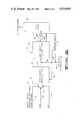
- FIG. 1is a schematic flow diagram depicting the process of the present invention for reducing the amount of NO x in a combustion effluent produced by the combustion of an industrial waste stream containing chemically bound nitrogen;
- FIG. 2is a schematic flow diagram showing the process of the present invention for reducing the amount of NO x in a combustion effluent of an industrial waste stream containing chemically bound nitrogen wherein a heat exchange and recycle effluent are employed.
- the present inventionrelates to an improved process for reducing the amount of nitrogen oxides (NO x ), the present process comprising the combustion of industrial waste streams containing chemically bound nitrogen so that the combustion products of the present process may be vented into the atmosphere without harm to the environment.
- Liquid or gaseous streams containing chemically bound nitrogencan be treated using the process of the present invention.
- Illustrative of such streamsare: NO x bearing waste streams; ammonia waste streams; coke oven gases; nitration process gases; and the waste streams of a nitroparaffin plant and its offsites.
- composition of the chemical waste streamssuch as mentioned above will vary substantially. However, all these streams contain chemically bound nitrogen which, when subjected to a combustion process, produces nitrogen oxides (NO x ). Further, while such streams are suitable for injection into a combustion chamber in the presence of hydrocarbon fuels, they frequently contain components which make their direct atmospheric discharge environmentally unacceptable.
- chemically bound nitrogenis to be understood to include compounds of nitrogen with hydrogen, oxygen or carbon, singly or in combination, as for example, nitrogen oxides, ammonia, nitromethane, acetonitrile, propionitrile, urea and the like.
- the "lower flammability limit”is the minimum concentration of an oxidizable gas in air or oxygen below which propagation of flame does not occur upon contact with the ignition source.
- the “upper flammability limit”is the maximum concentration of oxidizable gas in air or oxygen, above which flame propagation does not occur.
- the source of ignitionmust usually be one which will create a localized temperature in the mixture of oxidizable gas in air or oxygen above the minimum ignition temperature. This results in rapid oxidation and flame propagation within the concentration ranges set by the lower and upper flammability limits.
- the oxygen and/or fuel concentrations within a stream required to prevent flame propagation through that streamwill depend upon the combustibles present as well as the nature of inerts. In general, organic combustible mixtures will not propagate a flame within them if the oxygen in these mixtures is below about 13 and 15 volume percent respectively, for nitrogen and carbon dioxide as the inert gas component, and for a complicated molecular compound such as acetone for the fuel. For a simpler fuel molecule such as methane or propane, the oxygen requirement is reduced a little, to about 12 and 14 volume percent, and for a diatomic molecule such as hydrogen or carbon monoxide as the fuel, the oxygen must be reduced quite a bit further, to about 5 and 6%. Flame-propagation oxygen and fuel requirements for typical combustibles at ambient conditions are given in Table I.
- a reduction zone 10is depicted schematically which comprises a burner 12 and a refractory lined steel reaction shell 14.
- a stream 16 containing chemically bound nitrogensuch as a gaseous stream containing nitrogen oxides, is supplied to the burner 12 via a conduit.
- the stream 16may also contain combustible hydrocarbons.
- an air stream 18 and a fuel stream 20are also injected into the burner 12 via conduits.
- the fuelcan be any suitable hydrocarbon or other reducing agent which is preferably substantially completely oxidized to carbon dioxide and water upon combustion.
- the fuel 20 injected into the burner 12 of the reduction zone 10can comprise paraffinic, olefinic, or aromatic hydrocarbon compounds, including mixtures thereof, such as gasoline and fuel oil; oxygenated hydrocarbons such as aldehydes, ketones or acids; or nitrated hydrocarbons and similar compounds.
- the fuel 20will have a low molecular weight, and comprise, for example, methane, ethane, and mixtures thereof, such as natural gas.
- the amount and rate of injection of fuel into the burner 12 of the reduction zone 10can vary widely and will depend to a large extent upon the amount of hydrocarbon component present in the chemical waste stream being processed.
- the fuel 20is injected into the burner 12 in an amount sufficient to effect a stoichiometric excess of the hydrocarbons component, based on the amount of available oxygen, in the reduction zone 10.
- the amount of fuel 20 injected into the burner 12should not exceed 200 percent of the stoichiometric requirement based on the amount of available oxygen to reduce the chemically bound nitrogen present in the waste steam.
- the temperature of the reduction zone 10is maintained at a level above about 2000 F.
- the temperature of the reduction zonebe controlled so as to be less than about 3000 F. Therefore, the effective temperature range at which the reduction zone 10 is maintained is greater than about 2000 F. but less than about 3000 F. to insure that the chemically bound nitrogen present in the waste stream 16 reacts with the air stream 18 and the fuel stream 20 to form such constituents as nitrogen, carbon dioxide, and water vapor, and such intermediate combustibles as hydrogen and carbon monoxide.
- a combustion effluent 22is discharged from the reduction zone 10 and forms a reduction product stream which is composed primarily of nitrogen, carbon dioxide, water vapor, and intermediate combustibles, principally hydrogen and carbon monoxide formed as a result of the dissociation and partial oxidation of the excess fuel present in the reduction zone 10.
- the combustion effluent 22is withdrawn from the reduction zone 10 via a conduit and passes to an oxidation zone 24.
- the combustion effluent 22, prior to introduction into the oxidation zone 24,is mixed with an oxygen-containing gaseous stream 26 supplied via a conduit to provide a stoichiometric excess of oxygen, relative to the amount of combustibles present in the combustion effluent 22, and which at the same time, provides a reaction temperature in the oxidation zone 24 of between about 1600° F., and to about 1800 F.
- a reaction temperature in the oxidation zone 24of between about 1600° F., and to about 1800 F.
- the oxygen-containing gaseous stream 26is desirably a diluted gaseous stream containing an effective amount of oxygen but insufficient to propagate a flame in stream 26.
- the gaseous stream 26may be an air stream or oxygen-bearing gas stream 26A which is diluted with an inert diluent 28 which is introduced via another conduit so that the diluted gaseous stream 26 has an insufficiency of oxygen to propagate a flame within itself.
- Suitable diluents which may be employed to dilute the oxygen-containing gaseous stream 26Aare nitrogen, carbon dioxide, water vapor, and mixtures thereof.
- the diluted gaseous stream 26is mixed with the combustion effluent 22, resulting in full oxidation of the combustibles present but with minimum reformation of NO x in the combustion effluent in the oxidation zone 24 because high temperatures and high oxygen concentrations are avoided in said oxidation zone 24.
- the gaseous stream 26A and the diluent 28can be supplied from any suitable sources (not shown).
- an effective amount of oxygencan be added to a recycle stream produced by the process, as will be described hereinafter with reference to FIG. 2, to provide a diluted gaseous stream containing the desired amount of oxygen for mixing with the combustion effluent 22 prior to injecting the combustion effluent into the oxidation zone 24.
- the oxidation zone 24is preferably a refractory lined steel shell 30.
- the oxidation products stream vented to the atmosphere via the stack 34is composed of nitrogen, carbon dioxide, water vapor and oxygen, the oxidation products stream being substantially free of smoke, combustibles and nitrogen oxides (NO x ) and environmentally safe.
- the burner 12 of the reduction zone 10is fed the waste chemical stream 16, the air stream 18 and the fuel stream 20 which are combusted in he reaction shell 14 to discharge the combustion effluent 22.
- the oxygen-containing gaseous stream 26is mixed with the combustion effluent 22, the combined streams passing to the oxidation zoner 24.
- the discharge from the oxidation zone 24is the oxidation products stream 32.
- a heat exchanger 40such as a waste heat boiler, a superheater, an economizer or combination thereof, is operably connected to the conduit passing the oxidation products stream 32 so that the oxidation products are in heat exchange relationship with a coolant in the heat exchanger 40 for the recovery of useful energy, a typical coolant being steam.
- the cooled oxidation products stream 32A exiting the heat exchanger 40may be routed to the vent stack 34 for venting to the atmosphere, or a portion of the cooled oxidation products stream 32A may be recycled to various stages of the process via a conduit 42 which communicates with the cooled oxidation products stream 32A.
- a cooling fluidmay be injected into the reaction shell 14 of the reduction zone 10 via a conduit 44 which communicates with the conduit 42 in FIG. 2.
- a conduit 44which communicates with the conduit 42 in FIG. 2.
- other sources of coolantsdesirably an inert gas such as nitrogen, carbon dioxide, water vapor, or mixtures thereof, can be supplied from an independent source (not shown), but as shown, the cooling fluid 44 is a recycle stream consisting of a portion of the cooled oxidation products stream 32A.
- a portion of the cooled oxidation products stream 32Ais passed via the conduits 42 and 44 to the reaction shell 14 and dispersed about the flame to cool the flame envelope, thus insuring that the reduction zone 10 is maintained at a temperature less than about 3000 F.
- a second portion of the cooled oxidation products stream 32Amay be passed via the conduit 42 to the conduit passing the gaseous stream 26A as the diluent 28.
- the diluted gaseous stream 26is mixed with the combustion effluent 22.
- the remaining portion of the cooled oxidation products stream 32A, that which is not passed through the conduit 42,may be vented to the stack 34.
- a waste stream 16consisting of 150 mols per hour total and containing 2 mols per hour of nitrogen oxides (NO x ) is injected into the burner 12 of the reduction zone 10.
- Methane fuel 20is introduced into the burner 12 at a rate of 13.75 mols per hour to provide a stoichiometric excess of hydrocarbon relative to the available oxygen (both free and bound as oxides of nitrogen expressed as NO 2 , NO x ) of 25 percent.
- the temperature in the reaction shell 14 of the reduction zone 10is 2600° F.
- the reduction product streami.e. the combustion effluent stream 22 is removed from the reaction shell 14, and such stream contains a mixture of carbon dioxide, water vapor, nitrogen, carbon monoxide, and hydrogen.
- the flow rate of the air stream 26is 40.91 mols per hour and the flow rate of the inert diluent stream 28 from conduit 42 is 171.42 mols per hour.
- the concentration of oxygenis sufficient to oxidize the combustibles present in the combustion effluent stream 22 and yield 1.5 percent oxygen in the oxidation products stream 32 recovered from the oxidation zone 24.
- the temperature in the oxidation zone 24is 1800° F.
- the oxidation products stream 32 withdrawn from the oxidation zone 24passes through the heat exchanger 40 which cools the oxidation effluent to 400° F.
- the oxidation effluentconsists primarily of carbon dioxide, water vapor, nitrogen and oxygen.
- composition, flow rate and temperature of the various streams, at selected locations in the process described above,are tabulated in Table II.
- the concentration of oxygen in the air stream passed to the oxidation zone 22is 5.26 percent if all the oxidation products stream is recycled as diluent, and the concentration of combustibles, i.e. hydrogen and carbon monoxide, in the combustion effluent stream is 1.47 percent, respectively, for a total of 2.94 percent combustibles.
- the amount of combustibles, i.e., hydrogen and carbon monoxide in the combustion effluentwould be 4.9 percent, respectively, for a total of 9.8 percent combustibles.
- a waste stream 16consisting of 90 mols per hour of air and containing 10 mols per hour of ammonia is injected into the burner 12 of the reduction zone 10.
- the hydrocarbon fuel 20is methane, which is introduced into the burner 12 at a rate of 7.98 mols per hour to provide a stoichiometric excess of hydrocarbon relative to the available oxygen (both free and bound) of eighteen percent (18%).
- the temperature in the reaction shell 14is controlled to 2600° F. by injecting 50.28 mols per hour of the flue gas 44 at 400° F. into the reaction shell 14.
- the combustion effluent 22is removed from the reaction shell 14 via the conduit 22, and such stream contains a mixture of carbon dioxide, water vapor, nitrogen, carbon monoxide, and hydrogen.
- the combustion effluent stream 22, which has a temperature of 2600° F.,is mixed with an air stream 26A which is diluted with a recycle diluent stream 28 consisting of oxidation effluent recovered from the oxidation zone 24 to produce an oxygen containing stream having 10 percent by volume oxygen.
- the flow rate of the air stream 26is 26.30 mols per hour and the inert diluent flow rate through conduit 28 is 143.00 mols per hour.
- the concentration of oxygenis sufficient to oxidize the combustibles in the combustion effluent stream 22 and yield 1.5% oxygen in the oxidation products effluent 32 recovered from the oxidation zone 24.
- the temperature in the oxidation zone 24is 1800° F.
- the oxidation products effluent 32 withdrawn from the oxidation zone 24passes through the heat exchanger 40 which cools the oxidation products effluent 32 to 400° F.
- the oxidation products effluent 32less the portion recycled as diluent and cooling fluid through the conduit 42, flows to the vent stack 34 where it is vented to the atmosphere at a rate of 137.78 mols per hour.
- the oxidation products effluent 32consists primarily of carbon dioxide, water vapor, nitrogen, and oxygen.
- the flow rate of the portion of the cooled oxidation effluent through conduit 42 for use as cooling fluid and diluent, as set forth above,is 193.28 mols per hour.
- composition, flow rate and temperature of the various streams, at selected locations in the process described above,are tabulated in Table III which follows.
- An ammonia vent stream 16was synthesized by combining 1.95 mols per hour of ammonia with 104.10 mols per hour of air. The ammonia was monitored by orifice pressure drop and controlled with a hand valve. The air was monitored by annubar differential pressure reading and controlled by a manual damper. Fuel gas 20 was combined with the ammonia/air stream across a spin type burner 12 at a rate of 13.58 mols per hour and monitored by pressure drop across the orifice openings in the drilled tip.
- the fuel gas 20was controlled by a manual hand valve to an amount in excess of the available oxygen in the ammonia/air stream 16 to create an overall reducing atmosphere 10 as monitored by a teledyne oxygen/combustibles analyzer.
- the temperature in this zone 10was 2560 F.
- Secondary oxidation air 26A at a rate of 33.6 mols per hourwas monitored by an annubar and controlled by a manual damper.
- Diluent stream 28was mixed with the secondary oxidation air 26A at a rate of 104.4 mol per hour as monitored by orifice differential pressure.
- the excess combustibleswere oxidized in zone 24 at a temperature of 1422 F.
Landscapes
- Engineering & Computer Science (AREA)
- Chemical & Material Sciences (AREA)
- General Engineering & Computer Science (AREA)
- Mechanical Engineering (AREA)
- Environmental & Geological Engineering (AREA)
- Analytical Chemistry (AREA)
- General Chemical & Material Sciences (AREA)
- Oil, Petroleum & Natural Gas (AREA)
- Chemical Kinetics & Catalysis (AREA)
- Health & Medical Sciences (AREA)
- Biomedical Technology (AREA)
- Combustion & Propulsion (AREA)
- Treating Waste Gases (AREA)
Abstract
Description
TABLE I ______________________________________ Min. % O.sub.2 for Flame Propagation Min. % Fuel for N.sub.2 CO.sub.2 Flame Propagation diluent diluent (Lower Explosive Limit) ______________________________________ Methane 12.1 14.6 5.3 Propane 11.4 14.3 2.4 Acetone 13.5 15.6 3.0 Carbon monoxide 5.6 5.9 12.5 Hydrogen 5.0 5.9 4.1 ______________________________________
TABLE II __________________________________________________________________________PROCESS CONDITIONS (FIG. 1) Oxidation NOx Con- Hydro- Combustion Oxygen Con- Stream to Vent taining carbon Effluent taining Diluent Oxidation Stream to Gas (16) Fuel (20) Stream (22) Stream (26A) Gas (28) Zone (26A + 28) Atmosphere __________________________________________________________________________Flow Rate 150.00 13.75 171.01 40.91 171.42 212.33 204.66 (Mol/Hr) Temperature 200 80 2600 80 400 324 400 (F.) Composition (Mol %) N.sub.2 75.33 -- 65.60 79.00 71.01 72.55 71.01 O.sub.2 12.67 -- -- 21.00 1.51 5.26 1.51 NO.sub.x 2.00 -- -- -- less than -- less than 150 ppm 150 ppm CH.sub.4 -- 100.00 -- -- -- -- -- CO.sub.2 3.33 -- 10.39 -- 9.16 7.40 9.16 H.sub.2 O 6.67 -- 17.57 -- 18.32 14.79 18.32 CO -- -- 3.22 -- -- -- -- H.sub.2 -- -- 3.22 -- -- -- -- __________________________________________________________________________
TABLE III __________________________________________________________________________PROCESS CONDITIONS (FIG. 2) Cooling Oxidation Vented NOx Con- Hydro- Fluid to Combustion Oxygen Con- Stream to Oxidation taining carbon Reduction Products taining Oxidation Products Gas (16) Fuel (20) Zone (44) Stream (22) Stream (26A) Zone (26A + 28) Stream __________________________________________________________________________Flow Rate 100.00 7.98 50.28 164.07 26.30 143.00 137.78 (Mol/Hr) Temperature 80 80 400 2600 80 400 400 (F.) Composition (Mol %) N.sub.2 71.10 -- 70.40 67.43 79.00 70.40 70.40 O.sub.2 19.90 -- 1.50 -- 21.00 1.50 1.50 NH.sub.3 10.00 -- -- -- -- -- -- CH.sub.4 -- 100.00 -- -- -- -- -- CO.sub.2 -- -- 5.79 5.91 -- 5.79 5.79 H.sub.2 O -- -- 22.47 22.31 -- 22.47 22.47 CO -- -- -- 1.49 -- -- -- H.sub.2 -- -- -- 2.86 -- -- -- __________________________________________________________________________
TABLE IV __________________________________________________________________________PROCESS CONDITIONS Combined Fuel Air Stream Combustion Oxidation Streams Stream Stream Diluent Effluent Products (16,18) (20) (26A) (28) (22) Stream (32) __________________________________________________________________________Flow Rate 106.05 13.58 27.6 104.44 -- -- (Mol/Hr) Temperature 70 70 70 406 2560 1422 (F.) Composition (Mol %) N.sub.2 75.81 -- 77.67 -- 66.10 41.68 O.sub.2 20.18 20.58 -- -- 7.15 NH.sub.3 1.84 -- -- -- -- -- CH.sub.4 -- 100 -- -- -- -- (Assumed) CO.sub.2 -- -- -- -- 10.66 3.66 H.sub.2 O 2.17 -- 1.75 100 18.42 47.50 CO -- -- -- -- 2.07 -- H.sub.2 -- -- -- -- 2.13 -- NO.sub.x -- -- -- -- 87 ppm 71 ppm __________________________________________________________________________
Claims (22)
Priority Applications (1)
| Application Number | Priority Date | Filing Date | Title |
|---|---|---|---|
| US06/523,644US4519993A (en) | 1982-02-16 | 1983-08-15 | Process of conversion for disposal of chemically bound nitrogen in industrial waste gas streams |
Applications Claiming Priority (2)
| Application Number | Priority Date | Filing Date | Title |
|---|---|---|---|
| US06/348,840US4405587A (en) | 1982-02-16 | 1982-02-16 | Process for reduction of oxides of nitrogen |
| US06/523,644US4519993A (en) | 1982-02-16 | 1983-08-15 | Process of conversion for disposal of chemically bound nitrogen in industrial waste gas streams |
Related Parent Applications (1)
| Application Number | Title | Priority Date | Filing Date |
|---|---|---|---|
| US06/348,840Continuation-In-PartUS4405587A (en) | 1982-02-16 | 1982-02-16 | Process for reduction of oxides of nitrogen |
Publications (1)
| Publication Number | Publication Date |
|---|---|
| US4519993Atrue US4519993A (en) | 1985-05-28 |
Family
ID=26995921
Family Applications (1)
| Application Number | Title | Priority Date | Filing Date |
|---|---|---|---|
| US06/523,644Expired - LifetimeUS4519993A (en) | 1982-02-16 | 1983-08-15 | Process of conversion for disposal of chemically bound nitrogen in industrial waste gas streams |
Country Status (1)
| Country | Link |
|---|---|
| US (1) | US4519993A (en) |
Cited By (26)
| Publication number | Priority date | Publication date | Assignee | Title |
|---|---|---|---|---|
| US4617046A (en)* | 1985-10-04 | 1986-10-14 | Gas Research Institute | Method for the heat processing of glass and glass forming material |
| US5055278A (en)* | 1988-07-12 | 1991-10-08 | Apparatebau Rothemuhle Brandt | Method for decreasing nitrogen oxides (nox) in waste furnace gases |
| EP0463218A1 (en)* | 1990-06-29 | 1992-01-02 | Joachim Dr.-Ing. Wünning | Method and device for combustion of fuel in a combustion chamber |
| US5269235A (en)* | 1988-10-03 | 1993-12-14 | Koch Engineering Company, Inc. | Three stage combustion apparatus |
| US5354544A (en)* | 1993-12-27 | 1994-10-11 | Ford Motor Company | Selective reduction of nitric oxide |
| US5372706A (en)* | 1993-03-01 | 1994-12-13 | Mobil Oil Corporation | FCC regeneration process with low NOx CO boiler |
| US5441404A (en)* | 1993-01-29 | 1995-08-15 | Gordan-Piatt Energy Group, Inc. | Burner assembly for reducing nitrogen oxides during combustion of gaseous fuels |
| US5449854A (en)* | 1993-11-26 | 1995-09-12 | The Boc Group, Inc. | Method and incinerator for incinerating halogenated organic compounds |
| WO1997008269A1 (en)* | 1995-08-30 | 1997-03-06 | Mobil Oil Corporation | Fcc nox reduction by turbulent/laminar thermal conversion |
| US5617715A (en)* | 1994-11-15 | 1997-04-08 | Massachusetts Institute Of Technology | Inverse combined steam-gas turbine cycle for the reduction of emissions of nitrogen oxides from combustion processes using fuels having a high nitrogen content |
| US5681158A (en)* | 1995-03-14 | 1997-10-28 | Gfk Consulting Limited | Single-stage process for disposal of chemically bound nitrogen in industrial waste streams |
| US5705053A (en)* | 1995-08-30 | 1998-01-06 | Mobil Oil Corporation | FCC regenerator NOx reduction by homogeneous and catalytic conversion |
| US6109911A (en)* | 1997-10-10 | 2000-08-29 | Kvaerner Pulping Oy | Method and arrangement for optimizing oxidation during burning of gaseous and liquid fuels |
| US6348178B1 (en) | 1996-11-01 | 2002-02-19 | Noxtech, Inc. | Method for reducing NOx from exhaust gases produced by industrial processes |
| US6908297B2 (en)* | 2000-05-26 | 2005-06-21 | Rohm And Haas Company | Hydrogen-fueled flare system |
| US20060008757A1 (en)* | 2004-07-06 | 2006-01-12 | Zamansky Vladimir M | Methods and systems for operating low NOx combustion systems |
| US20070140942A1 (en)* | 2005-12-21 | 2007-06-21 | Lee Rosen | Reduction of CO and NOx in regenerator flue gas |
| WO2009070563A1 (en)* | 2007-11-27 | 2009-06-04 | John Zink Company, Llc | Flameless thermal oxidation apparatus and methods |
| GB2457564A (en)* | 2008-02-25 | 2009-08-26 | Gen Electric | Combustion system with reduced nitrogen oxide emissions |
| US20110207063A1 (en)* | 2008-06-18 | 2011-08-25 | Kuang-Tsai Wu | Reduction of co and nox in full burn regenerator flue gas |
| WO2016055511A1 (en)* | 2014-10-07 | 2016-04-14 | Linde Aktiengesellschaft | Incineration of waste |
| EP3249295A4 (en)* | 2015-01-21 | 2018-08-22 | Taiyo Nippon Sanso Corporation | Exhaust gas treatment method and exhaust gas treatment device |
| GB2571793A (en)* | 2018-03-09 | 2019-09-11 | Edwards Ltd | Abatement |
| US20210364163A1 (en)* | 2018-05-22 | 2021-11-25 | Mitsubishi Power, Ltd. | Burner and combustion device |
| WO2022090737A3 (en)* | 2020-11-02 | 2022-08-18 | Edwards Limited | Gas abatement by plasma |
| EP4060230A1 (en)* | 2021-03-19 | 2022-09-21 | Alfa Laval Corporate AB | An arrangement for combusting purge gas and a method thereof |
Citations (11)
| Publication number | Priority date | Publication date | Assignee | Title |
|---|---|---|---|---|
| GB667342A (en)* | 1949-06-17 | 1952-02-27 | Ciba Ltd | Method of rendering nitrous gases innocuous |
| US3860384A (en)* | 1972-05-25 | 1975-01-14 | Intelcon Rad Tech | Method to control NOX formation in fossil-fueled boiler furnaces |
| US3867507A (en)* | 1972-04-24 | 1975-02-18 | Exxon Research Engineering Co | Method for removing the oxides of nitrogen as air contaminants |
| US3873671A (en)* | 1969-03-27 | 1975-03-25 | Zink Co John | Process for disposal of oxides of nitrogen |
| US3911083A (en)* | 1972-02-24 | 1975-10-07 | Zink Co John | Nitrogen oxide control using steam-hydrocarbon injection |
| US4144313A (en)* | 1976-06-04 | 1979-03-13 | Bayer Aktiengesellschaft | Method of purifying gases by combustion |
| JPS5438431A (en)* | 1977-09-02 | 1979-03-23 | Hitachi Ltd | Turbosupercharger |
| JPS5450470A (en)* | 1977-09-30 | 1979-04-20 | Mitsubishi Heavy Ind Ltd | Decreasing method for nitrogen oxides contained in exhaust gas |
| US4244325A (en)* | 1979-03-01 | 1981-01-13 | John Zink Company | Disposal of oxides of nitrogen and heat recovery in a single self-contained structure |
| US4316878A (en)* | 1979-02-08 | 1982-02-23 | Nittetu Chemical Engineering Ltd. | Method for the combustive treatment of waste fluids containing nitrogen compounds |
| US4405587A (en)* | 1982-02-16 | 1983-09-20 | Mcgill Incorporated | Process for reduction of oxides of nitrogen |
- 1983
- 1983-08-15USUS06/523,644patent/US4519993A/ennot_activeExpired - Lifetime
Patent Citations (11)
| Publication number | Priority date | Publication date | Assignee | Title |
|---|---|---|---|---|
| GB667342A (en)* | 1949-06-17 | 1952-02-27 | Ciba Ltd | Method of rendering nitrous gases innocuous |
| US3873671A (en)* | 1969-03-27 | 1975-03-25 | Zink Co John | Process for disposal of oxides of nitrogen |
| US3911083A (en)* | 1972-02-24 | 1975-10-07 | Zink Co John | Nitrogen oxide control using steam-hydrocarbon injection |
| US3867507A (en)* | 1972-04-24 | 1975-02-18 | Exxon Research Engineering Co | Method for removing the oxides of nitrogen as air contaminants |
| US3860384A (en)* | 1972-05-25 | 1975-01-14 | Intelcon Rad Tech | Method to control NOX formation in fossil-fueled boiler furnaces |
| US4144313A (en)* | 1976-06-04 | 1979-03-13 | Bayer Aktiengesellschaft | Method of purifying gases by combustion |
| JPS5438431A (en)* | 1977-09-02 | 1979-03-23 | Hitachi Ltd | Turbosupercharger |
| JPS5450470A (en)* | 1977-09-30 | 1979-04-20 | Mitsubishi Heavy Ind Ltd | Decreasing method for nitrogen oxides contained in exhaust gas |
| US4316878A (en)* | 1979-02-08 | 1982-02-23 | Nittetu Chemical Engineering Ltd. | Method for the combustive treatment of waste fluids containing nitrogen compounds |
| US4244325A (en)* | 1979-03-01 | 1981-01-13 | John Zink Company | Disposal of oxides of nitrogen and heat recovery in a single self-contained structure |
| US4405587A (en)* | 1982-02-16 | 1983-09-20 | Mcgill Incorporated | Process for reduction of oxides of nitrogen |
Cited By (47)
| Publication number | Priority date | Publication date | Assignee | Title |
|---|---|---|---|---|
| US4617046A (en)* | 1985-10-04 | 1986-10-14 | Gas Research Institute | Method for the heat processing of glass and glass forming material |
| US5055278A (en)* | 1988-07-12 | 1991-10-08 | Apparatebau Rothemuhle Brandt | Method for decreasing nitrogen oxides (nox) in waste furnace gases |
| US5269235A (en)* | 1988-10-03 | 1993-12-14 | Koch Engineering Company, Inc. | Three stage combustion apparatus |
| EP0463218A1 (en)* | 1990-06-29 | 1992-01-02 | Joachim Dr.-Ing. Wünning | Method and device for combustion of fuel in a combustion chamber |
| US5441404A (en)* | 1993-01-29 | 1995-08-15 | Gordan-Piatt Energy Group, Inc. | Burner assembly for reducing nitrogen oxides during combustion of gaseous fuels |
| US5722821A (en)* | 1993-01-29 | 1998-03-03 | Gordon-Piatt Energy Group, Inc. | Burner assembly for reducing nitrogen oxides during combustion of gaseous fuels |
| US5372706A (en)* | 1993-03-01 | 1994-12-13 | Mobil Oil Corporation | FCC regeneration process with low NOx CO boiler |
| US5449854A (en)* | 1993-11-26 | 1995-09-12 | The Boc Group, Inc. | Method and incinerator for incinerating halogenated organic compounds |
| US5609104A (en)* | 1993-11-26 | 1997-03-11 | The Boc Group, Inc. | Incinerator for incinerating halogenated organic compounds |
| US5354544A (en)* | 1993-12-27 | 1994-10-11 | Ford Motor Company | Selective reduction of nitric oxide |
| US5617715A (en)* | 1994-11-15 | 1997-04-08 | Massachusetts Institute Of Technology | Inverse combined steam-gas turbine cycle for the reduction of emissions of nitrogen oxides from combustion processes using fuels having a high nitrogen content |
| US5681158A (en)* | 1995-03-14 | 1997-10-28 | Gfk Consulting Limited | Single-stage process for disposal of chemically bound nitrogen in industrial waste streams |
| US5705053A (en)* | 1995-08-30 | 1998-01-06 | Mobil Oil Corporation | FCC regenerator NOx reduction by homogeneous and catalytic conversion |
| US5716514A (en)* | 1995-08-30 | 1998-02-10 | Mobil Oil Corporation | FCC NOx reduction by turbulent/laminar thermal conversion |
| WO1997008269A1 (en)* | 1995-08-30 | 1997-03-06 | Mobil Oil Corporation | Fcc nox reduction by turbulent/laminar thermal conversion |
| US6348178B1 (en) | 1996-11-01 | 2002-02-19 | Noxtech, Inc. | Method for reducing NOx from exhaust gases produced by industrial processes |
| US6109911A (en)* | 1997-10-10 | 2000-08-29 | Kvaerner Pulping Oy | Method and arrangement for optimizing oxidation during burning of gaseous and liquid fuels |
| US6908297B2 (en)* | 2000-05-26 | 2005-06-21 | Rohm And Haas Company | Hydrogen-fueled flare system |
| US20060008757A1 (en)* | 2004-07-06 | 2006-01-12 | Zamansky Vladimir M | Methods and systems for operating low NOx combustion systems |
| US7168947B2 (en)* | 2004-07-06 | 2007-01-30 | General Electric Company | Methods and systems for operating combustion systems |
| US7470412B2 (en) | 2005-12-21 | 2008-12-30 | Praxair Technology, Inc. | Reduction of CO and NOx in regenerator flue gas |
| KR101354809B1 (en) | 2005-12-21 | 2014-01-22 | 프랙스에어 테크놀로지, 인코포레이티드 | Reduction of co and nox in regenerator flue gas |
| US20070140942A1 (en)* | 2005-12-21 | 2007-06-21 | Lee Rosen | Reduction of CO and NOx in regenerator flue gas |
| EP2314367A2 (en) | 2005-12-21 | 2011-04-27 | Praxair Technology, Inc. | Reduction of CO and NOx in regenerator flue gas |
| EP2314367A3 (en)* | 2005-12-21 | 2011-05-25 | Praxair Technology, Inc. | Reduction of CO and NOx in regenerator flue gas |
| WO2007075397A1 (en)* | 2005-12-21 | 2007-07-05 | Praxair Technology, Inc. | Reduction of co and nox in regenerator flue gas |
| CN101384335B (en)* | 2005-12-21 | 2012-08-01 | 普莱克斯技术有限公司 | Reduction of CO and NOx in regenerator flue gas |
| CN102430329B (en)* | 2005-12-21 | 2014-10-29 | 普莱克斯技术有限公司 | Reduction of CO and NOx in regenerator flue gas |
| WO2009070563A1 (en)* | 2007-11-27 | 2009-06-04 | John Zink Company, Llc | Flameless thermal oxidation apparatus and methods |
| CN101874180B (en)* | 2007-11-27 | 2012-10-03 | 约翰津克公司 | Flameless thermal oxidation apparatus and method |
| GB2457564A (en)* | 2008-02-25 | 2009-08-26 | Gen Electric | Combustion system with reduced nitrogen oxide emissions |
| GB2457564B (en)* | 2008-02-25 | 2013-01-30 | Gen Electric | Combustion systems and processes for burning fossil fuel with reduced nitrogen oxide emissions |
| US8430665B2 (en) | 2008-02-25 | 2013-04-30 | General Electric Company | Combustion systems and processes for burning fossil fuel with reduced nitrogen oxide emissions |
| US20110207063A1 (en)* | 2008-06-18 | 2011-08-25 | Kuang-Tsai Wu | Reduction of co and nox in full burn regenerator flue gas |
| US8425870B2 (en) | 2008-06-18 | 2013-04-23 | Praxair Technology, Inc. | Reduction of CO and NOx in full burn regenerator flue gas |
| WO2016055511A1 (en)* | 2014-10-07 | 2016-04-14 | Linde Aktiengesellschaft | Incineration of waste |
| EP3249295A4 (en)* | 2015-01-21 | 2018-08-22 | Taiyo Nippon Sanso Corporation | Exhaust gas treatment method and exhaust gas treatment device |
| US10502417B2 (en) | 2015-01-21 | 2019-12-10 | Taiyo Nippon Sanso Corporation | Exhaust gas treatment method and exhaust gas treatment device |
| GB2571793A (en)* | 2018-03-09 | 2019-09-11 | Edwards Ltd | Abatement |
| WO2019171067A1 (en)* | 2018-03-09 | 2019-09-12 | Edwards Limited | Abatement by combustion |
| US20210364163A1 (en)* | 2018-05-22 | 2021-11-25 | Mitsubishi Power, Ltd. | Burner and combustion device |
| US11649962B2 (en)* | 2018-05-22 | 2023-05-16 | Mitsubishi Heavy Industries, Ltd. | Burner and combustion device |
| WO2022090737A3 (en)* | 2020-11-02 | 2022-08-18 | Edwards Limited | Gas abatement by plasma |
| EP4060230A1 (en)* | 2021-03-19 | 2022-09-21 | Alfa Laval Corporate AB | An arrangement for combusting purge gas and a method thereof |
| WO2022194804A1 (en)* | 2021-03-19 | 2022-09-22 | Alfa Laval Corporate Ab | An arrangement for combusting purge gas and a method thereof |
| TWI826962B (en)* | 2021-03-19 | 2023-12-21 | 瑞典商阿爾法拉瓦公司 | An arrangement for combusting purge gas and a method thereof |
| JP2024508927A (en)* | 2021-03-19 | 2024-02-28 | アルファ-ラヴァル・コーポレート・アーベー | Device and method for burning purge gas |
Similar Documents
| Publication | Publication Date | Title |
|---|---|---|
| US4519993A (en) | Process of conversion for disposal of chemically bound nitrogen in industrial waste gas streams | |
| US4405587A (en) | Process for reduction of oxides of nitrogen | |
| US4344486A (en) | Method for enhanced oil recovery | |
| US3900554A (en) | Method for the reduction of the concentration of no in combustion effluents using ammonia | |
| US4992249A (en) | Reduction of nitrogen- and carbon-based pollutants through the use of urea solutions | |
| US3873671A (en) | Process for disposal of oxides of nitrogen | |
| US4719092A (en) | Reduction of nitrogen-based pollutants through the use of urea solutions containing oxygenated hydrocarbon solvents | |
| CA1112426A (en) | Disposal of pcb | |
| US9884283B2 (en) | Method for treating sulphur-containing exhaust gases and device thereof | |
| US5718872A (en) | Apparatus for controlling the hydrogen sulfide concentration in the acid gas feedstock of a sulfur recovery unit | |
| US4368057A (en) | Method for reducing ammonia concentration in pre-combusted fuel gas using nitric oxide | |
| KR20010107570A (en) | Hydrogen-fueled flare system | |
| US5269235A (en) | Three stage combustion apparatus | |
| US4014982A (en) | Combined process for upgrading spent alkylation acid and reducing noxious gas content of waste gaseous streams | |
| US3988423A (en) | Method for removing harmful materials from waste gas | |
| US4423017A (en) | Process for reducing NO emissions | |
| US4391790A (en) | Method and apparatus for reducing the ammonia concentration of sulfur recovery facility gas streams | |
| US20080050302A1 (en) | Process for producing ammonium thiosulfate | |
| RU2085480C1 (en) | Method and thermal reactor for producing sulfur from at least one hydrogen sulfide-containing acidic gas | |
| CA1312447C (en) | Method for recovering sulfur from a feed gas stream containing hydrogen sulfide | |
| US4048293A (en) | Process for purifying a sulfur dioxide containing gas | |
| US4073862A (en) | Process for removing ammonia, hydrogen sulfide and hydrocyanic acid from gases | |
| US4012488A (en) | Process for the treatment of sulfur and nitrogen oxides formed during power generation | |
| US4682468A (en) | Non-catalytic method for reducing the NO emissions of gas turbines | |
| US6902713B1 (en) | Method for partially oxidizing a gas stream comprising hydrogen sulphide and ammonia |
Legal Events
| Date | Code | Title | Description |
|---|---|---|---|
| AS | Assignment | Owner name:MCGILL INCORPORATED 5800 WEST 68TH ST., CREEK COUN Free format text:ASSIGNMENT OF ASSIGNORS INTEREST.;ASSIGNORS:MC GILL, EUGENE C.;BELL, RONALD D.;REEL/FRAME:004167/0743 Effective date:19830815 | |
| STCF | Information on status: patent grant | Free format text:PATENTED CASE | |
| CC | Certificate of correction | ||
| FPAY | Fee payment | Year of fee payment:4 | |
| AS | Assignment | Owner name:IT-MCGILL POLLUTION CONTROL SYSTEMS, INC. AN OK Free format text:CHANGE OF NAME;ASSIGNOR:MCGILL ENVIRONMENTAL SYSTEMS, INC.;REEL/FRAME:005673/0160 Effective date:19901016 | |
| FEPP | Fee payment procedure | Free format text:PAT HLDR NO LONGER CLAIMS SMALL ENT STAT AS SMALL BUSINESS (ORIGINAL EVENT CODE: LSM2); ENTITY STATUS OF PATENT OWNER: LARGE ENTITY | |
| AS | Assignment | Owner name:MCGILL ENVIRONMENTAL SYSTEMS, INC., A CORP. OF OK, Free format text:MERGER;ASSIGNORS:MCGILL SYSTEMS MANAGEMENT, INC., A CORP. OF OK;MCGILL INTERNATIONAL, INC., A CORP. OF OK;MCGILL INCORPORATED, A CORP. OF OK (ALL MERGED INTO);AND OTHERS;REEL/FRAME:006047/0225 Effective date:19900824 | |
| AS | Assignment | Owner name:KOCH ENGINEERING COMPANY, INC. A KS CORPORATION, Free format text:ASSIGNMENT EFFECTIVE AS OF 5-15-1992;ASSIGNOR:IT-MCGILL POLLUTION CONTROL SYSTEMS, INC., AN OK CORPORATION;REEL/FRAME:006276/0631 Effective date:19920821 | |
| FPAY | Fee payment | Year of fee payment:8 | |
| FPAY | Fee payment | Year of fee payment:12 | |
| AS | Assignment | Owner name:KOCH-GLITSCH, INC., KANSAS Free format text:CHANGE OF NAME;ASSIGNOR:KOCH ENGINEERING, INC.;REEL/FRAME:009662/0124 Effective date:19980106 | |
| AS | Assignment | Owner name:JOHN ZINK COMPANY, LLC, OKLAHOMA Free format text:ASSIGNMENT OF ASSIGNORS INTEREST;ASSIGNOR:KOCH ENGINEERING COMPANY, INC., A KANSAS CORPORATION;REEL/FRAME:010247/0033 Effective date:19990819 |