US4519598A - Signature gathering machine with segment wheel calibrated to main drive shaft - Google Patents
Signature gathering machine with segment wheel calibrated to main drive shaftDownload PDFInfo
- Publication number
- US4519598A US4519598AUS06/596,233US59623384AUS4519598AUS 4519598 AUS4519598 AUS 4519598AUS 59623384 AUS59623384 AUS 59623384AUS 4519598 AUS4519598 AUS 4519598A
- Authority
- US
- United States
- Prior art keywords
- shaft
- wheel
- drive
- drive shaft
- driven
- Prior art date
- Legal status (The legal status is an assumption and is not a legal conclusion. Google has not performed a legal analysis and makes no representation as to the accuracy of the status listed.)
- Expired - Fee Related
Links
- 239000003292glueSubstances0.000claimsdescription12
- 230000008878couplingEffects0.000abstractdescription3
- 238000010168coupling processMethods0.000abstractdescription3
- 238000005859coupling reactionMethods0.000abstractdescription3
- 238000006073displacement reactionMethods0.000description7
- 238000000926separation methodMethods0.000description4
- 230000001133accelerationEffects0.000description2
- 238000010276constructionMethods0.000description2
- 238000004026adhesive bondingMethods0.000description1
- 230000001143conditioned effectEffects0.000description1
- 238000010586diagramMethods0.000description1
- 230000000694effectsEffects0.000description1
- 230000005484gravityEffects0.000description1
- 238000004519manufacturing processMethods0.000description1
- 239000000463materialSubstances0.000description1
- 230000001360synchronised effectEffects0.000description1
Images


Classifications
- B—PERFORMING OPERATIONS; TRANSPORTING
- B42—BOOKBINDING; ALBUMS; FILES; SPECIAL PRINTED MATTER
- B42C—BOOKBINDING
- B42C1/00—Collating or gathering sheets combined with processes for permanently attaching together sheets or signatures or for interposing inserts
- B42C1/10—Machines for both collating or gathering and interposing inserts
- B—PERFORMING OPERATIONS; TRANSPORTING
- B42—BOOKBINDING; ALBUMS; FILES; SPECIAL PRINTED MATTER
- B42B—PERMANENTLY ATTACHING TOGETHER SHEETS, QUIRES OR SIGNATURES OR PERMANENTLY ATTACHING OBJECTS THERETO
- B42B7/00—Permanently attaching objects, e.g. map sections, to sheets
Definitions
- This inventionrelates to signature gatherers of the kind in which folded sheets are delivered from separate pockets or hoppers to a moving gatherer which collects the signatures one atop another in successive cycles of the machine to complete a book which is afterwards bound and trimmed.
- the present inventionis concerned with a known delivery mechanism having a wheel for capturing an insert at the side of the signature gatherer, moving it past a glue dabber and releasing the insert to one of the signature sheets to which it is adhered by the glue.
- the object of the present inventionis to enable the known arrangement to be incorporated in a signature gatherer in which so-called pin-spacing on the gatherer may be a variable.
- the signature gathererordinarily comprises a chain or even a flat belt having spaced pins, lugs or the like which engage the trailing edges of the signatures to maintain the signatures in proper book array for binding.
- this pin-spacingmay vary because of different books, such that the spacing in one gatherer may be a 14" separation per machine cycle, while at another extreme the spacing may be as much as 20" per machine cycle.
- the known device for adhering the inserts to the successive signature groupscomprises a delivery wheel of definite circumference and we were faced with the problem of the plain fact that a match between the lineal speed of the gatherer and the insert wheel, at the time of releasing the insert to the gathered signatures, could only be a fortuitous event.
- the problemindeed was (or is) exacerbated by the fact that the wheel of the known device has two segments, feeding two inserts per 360° of wheel rotation which introduces the further difficulty that one rotation or cycle of the insert wheel would have to match two cycles of the signature gatherer, a machine cycle being defined herein as the movement of two successive gathering pins past a given point. Indeed the given point may be taken as the point where the insert sheet is to be released and adhered to the signature group.
- Another object of the inventionis to adopt a principle of calibration which itself can be easily corrected for a variation in pin spacing.
- an object of the present inventionis to solve the problem by using in part the principle of a Whitworth drive to enable the calibration to be effectively and readily accomplished.
- FIG. 1is a projection in a horizontal plane of certain equipment for capturing, delivering and releasing the insert to the signature;
- FIG. 2is a plan view on an enlarged scale of the drive means employed for calibrating
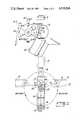
- FIG. 3is a side elevation of a machine constructed in accordance with the present invention.
- FIG. 4is a top plan view of the structure shown in FIG. 3 with a cover plate removed.
- the gathering chain (or belt) of a signature gatherermoves at a continuous lineal speed along a path 10.
- the two segments 15A and 15B of the wheelare displaced by 180° so that for each 360° turn successive inserts are transferred.
- the gathereris a chain supporting spaced pins 18 which move the gathered signatures past the hoppers which feed signatures successively to the gatherer, timed to the cyclical spacing of the pins.
- This spacingmay be 14" per unit of time or it may for example be 15" or 20" per unit of time, defined as a machine cycle.
- the cylical driveis generated by a so-called line shaft 20 which is the main drive shaft.
- the insert applying wheel and its related magazine and associated parts, FIG. 1,represent known equipment and do not constitute part of this invention.
- the wheel 15has a given circumference and it has a gear reduction box, FIG. 3, of fixed and determined ratios.
- RPgear reduction box
- the problemis solved under the present invention by interposing a coupling having the attribute of a so-called Whitworth drive, FIG. 2, interposed between the main machine drive and the drive of the wheel 15.
- the drive shaft 16 for the wheel 15is tilted, FIG. 3, and the segments 15A and 15B which carry the inserts to become part of the books are slanted so that the plane of the insert sheet at the time of release to the signature group will be substantially in the same plane due to the signature group being draped over the saddle SD.
- the wheel drive shaft 16is disposed within a gear box 24 and is rotated by meshed bevel gears 26 and 28, bevel gear 28 being driven by a sprocket 30 on the same shaft 32 as the bevel gear 28.
- the sprocket 30is driven by a chain 33 and this chain is driven in a manner to be described.
- the inserts to become part of the signature groupsare contained in a supply magazine 34, FIG. 1, and they feed by gravity to a transfer wheel 36 provided with grippers (not shown) which clamp the exposed edge of a fresh insert and withdraw it from the magazine in the course of rotation of the wheel 36.
- wheel 36has a driven shaft 38 rotated cyclically with the wheel drive shaft 16 by virtue of meshed bevel gears 42 and 44.
- a card or other sheet constituting the insert to be delivered from magazine 34has its edge presented to the mechanical grippers (not shown) on the wheel 36 by suction cups (not shown), and as the mechanical grippers move therepast they grab the exposed or presented edge of the insert to effectively and forcefully withdraw the insert from the magazine 34.
- the wheel segments 15A and 15Bare provided with air openings 15C.
- suctionprevails in the openings 15C so that the segment as 15B is conditioned to hold an insert when released by the wheel 36.
- the mechanical grippers on the wheel 36when opened release the insert to the wheel 15, held to the wheel segment by the suction.
- the signature gathererderives its speed from the main drive shaft 20.
- a hopper or signature pocket configuration 49positioned, as any other signature pocket, at one side of the gathering path 10.
- This pocket or hopperholds a supply of identical signatures which are fed one by one to the gathering chain to become part of the signature group and it may be assumed that the signature fed from pocket 49 will be the signature with which the insert is to be associated. Since the pocket delivery rate must be coincident with the lineal speed or rate of the gathering chain, the pocket feeder or drive shaft 50, FIG.
- a drive sprocket 52 on drive shaft 20coupled by a chain (not shown) to a driven sprocket 54 on the pocket feeder shaft 50.
- An idler or tensioning sprocket 56may be employed.
- chain 33is driven by a sprocket 33A on a driven shaft 58, FIGS. 3 and 4.
- the driven shaft 58lies in the same vertical plane as an opposed drive shaft 60 but as shown in FIG. 3, the two shafts are offset in this plane so that in the form shown the driven shaft 58 is displaced below the axis of the drive shaft 60.
- the drive shaft 60is provided with a drive sprocket 62, FIG.
- a chain 64which in turn is coupled to a driving sprocket 66 on the main drive shaft 20.
- the sprockets 62 and 66are of the same diameter and hence the drive shaft 60 is synchronized to the main drive shaft 20.
- a drive arm 70is fixed to the drive shaft 60.
- This drive shaftpresents a slot 72.
- a driven arm 74is coupled to the inner end of shaft 58 adjacent the inner end of the drive shaft 60.
- the driven arm 74at its free end, has a roller 76 pinned thereto and this roller is disposed in the slot 72 so that as the drive arm 70 rotates with the drive shaft 60, the driven arm 74 is rotated by virtue of the coupling represented by the roller 76 in the drive slot 72.
- Shaft 58is therefore driven by the rotating arm 74 and the rotation of shaft 58 is transmitted by the chain 33 to shaft 32 which, through the bevel gearing identified above, rotates the wheel shaft 16 and also wheel shaft 38.
- FIG. 2is a diagram showing movement of the roller 76 during a complete turn of the drive arm 70 on shaft 60. It can be seen that the roller 76 will traverse slot 72 from a point of maximum displacement (FAST) to a point of minimum displacement (SLOW) and then back in successive 180° of rotary movement. It can be visualized from FIG. 2 that when roller 76 is at and near its maximum displacement in slot 72 its arm 74 (and therefore driven shaft 58) must necessarily have maximum speed imparted thereto, whereas the converse is the case when the roller is at its minimum displacement in slot 72.
- FASTpoint of maximum displacement
- SLOWpoint of minimum displacement
- the angular velocity of the pin 76(w p ) is a function of the separation between the centers of rotation of the shafts 58 and 60 (a predetermined length b, FIG. 2) and the effective length of the driven arm 74 (which may be denoted c).
- the angular velocity of the pinis also a function of (-cos) of the angle x included between the radius (c) of arm 74 and the separation line denoted b in FIG. 2.
- Angle xvaries with the displacement b.
- the angular velocity of the pinsubscribes to the law of cosines and therefore includes the factor (-2bc cos x) so that it can be seen that the angular velocity of the pin is constantly varied in each 180° of turn of shaft 58 not only by the value of the cosine of x but also whether it is plus or minus.
- the net and practical effect for the purposes of the present inventionis as shown in FIG. 1 (remembering that wheel 15 has two revolutions per revolution of shaft 58) where the wheel 15 is constantly undergoing alternate acceleration and slowing in successive 90° turns. Wheel is turning slowly at significant and appropriate times, namely when the insert is being offset to the signature and when (concurrently) the opposed segment of wheel 15 is receiving a fresh insert from the transfer wheel 36.
- High acceleration at the time of applying the glue dabis not material because this is a mere jet or swipe proposition and no work is being done at the point opposite the glue dabber.
Landscapes
- Engineering & Computer Science (AREA)
- Mechanical Engineering (AREA)
- Collation Of Sheets And Webs (AREA)
- Folding Of Thin Sheet-Like Materials, Special Discharging Devices, And Others (AREA)
Abstract
Description
Claims (5)
Priority Applications (6)
| Application Number | Priority Date | Filing Date | Title |
|---|---|---|---|
| US06/596,233US4519598A (en) | 1984-04-02 | 1984-04-02 | Signature gathering machine with segment wheel calibrated to main drive shaft |
| IT8547798AIT1214402B (en) | 1984-04-02 | 1985-03-12 | IMPROVEMENT IN MACHINES FOR COLLECTING SIGNATURES |
| JP60050219AJPS60236797A (en) | 1984-04-02 | 1985-03-13 | Signature gathering machine |
| GB08507211AGB2156787B (en) | 1984-04-02 | 1985-03-20 | Signature gathering machine |
| CH1291/85ACH667427A5 (en) | 1984-04-02 | 1985-03-22 | CYCLE WORKING MACHINE FOR COLLECTING SIGNATURES. |
| DE19853510878DE3510878A1 (en) | 1984-04-02 | 1985-03-26 | CYCLE WORKING MACHINE FOR COLLECTING SIGNATURE SHEETS |
Applications Claiming Priority (1)
| Application Number | Priority Date | Filing Date | Title |
|---|---|---|---|
| US06/596,233US4519598A (en) | 1984-04-02 | 1984-04-02 | Signature gathering machine with segment wheel calibrated to main drive shaft |
Publications (1)
| Publication Number | Publication Date |
|---|---|
| US4519598Atrue US4519598A (en) | 1985-05-28 |
Family
ID=24386515
Family Applications (1)
| Application Number | Title | Priority Date | Filing Date |
|---|---|---|---|
| US06/596,233Expired - Fee RelatedUS4519598A (en) | 1984-04-02 | 1984-04-02 | Signature gathering machine with segment wheel calibrated to main drive shaft |
Country Status (6)
| Country | Link |
|---|---|
| US (1) | US4519598A (en) |
| JP (1) | JPS60236797A (en) |
| CH (1) | CH667427A5 (en) |
| DE (1) | DE3510878A1 (en) |
| GB (1) | GB2156787B (en) |
| IT (1) | IT1214402B (en) |
Cited By (8)
| Publication number | Priority date | Publication date | Assignee | Title |
|---|---|---|---|---|
| US4711440A (en)* | 1986-11-17 | 1987-12-08 | Mccain Manufacturing Corporation | Signature machine with counterpulse weight shuttle bar drive |
| US5287976A (en)* | 1990-10-31 | 1994-02-22 | R. R. Donnelley & Sons Company | System and method for co-mailing a plurality of diverse publications |
| US5316281A (en)* | 1993-01-12 | 1994-05-31 | International Business Machines Corporation | System and method for monitoring a document assembly system |
| US5326087A (en)* | 1993-01-12 | 1994-07-05 | Internationaal Business Machines Corporation | System and method for calibrating a document assembly system having multiple asynchronously operated sections |
| US5413321A (en)* | 1993-01-12 | 1995-05-09 | International Business Machines Corporation | System and method for operating a document assembly system |
| US5987461A (en)* | 1995-06-07 | 1999-11-16 | R.R. Donnelley & Sons Company | Co-mailing of diverse publications using an electronic press |
| US20010051964A1 (en)* | 1995-06-07 | 2001-12-13 | R.R. Donnelley & Sons Company | Imposition process and apparatus for variable imaging system |
| US7278094B1 (en) | 2000-05-03 | 2007-10-02 | R. R. Donnelley & Sons Co. | Variable text processing for an electronic press |
Families Citing this family (2)
| Publication number | Priority date | Publication date | Assignee | Title |
|---|---|---|---|---|
| DE4036824C2 (en)* | 1990-11-19 | 1994-11-24 | Lemke Wolfgang | Device for feeding a card to be stuck on |
| DE102004011978A1 (en)* | 2004-03-10 | 2005-09-29 | Hohner Maschinenbau Gmbh | Saddle stitcher with two working shafts |
Citations (7)
| Publication number | Priority date | Publication date | Assignee | Title |
|---|---|---|---|---|
| US1267354A (en)* | 1917-10-03 | 1918-05-28 | Cottrell C B & Sons Co | Sheet-collecting mechanism. |
| US1833311A (en)* | 1928-07-13 | 1931-11-24 | Winkler Alfred | Apparatus for insertion or assembly of paper sheets |
| US2626074A (en)* | 1949-06-17 | 1953-01-20 | Clarence W Vogt | Supplying sheet material articles |
| US3087721A (en)* | 1960-02-15 | 1963-04-30 | Chicago Machinery Lab Inc | Signature gathering and stitching machine |
| US3658318A (en)* | 1970-07-10 | 1972-04-25 | Mccall Corp | Method and apparatus for adding loose inserts to magazines |
| US3717337A (en)* | 1970-04-27 | 1973-02-20 | Mccain Mfg Co | Sheet or signature feeding machines |
| US4180255A (en)* | 1977-12-27 | 1979-12-25 | Harris Corporation | Wiper system inserter |
Family Cites Families (2)
| Publication number | Priority date | Publication date | Assignee | Title |
|---|---|---|---|---|
| CH538366A (en)* | 1971-08-13 | 1973-06-30 | Mueller Hans Grapha Masch | Device for gluing inserts to printed sheets |
| EP0127621A1 (en)* | 1982-06-04 | 1984-12-12 | FLENSBURG, Carl Gustav Anders | Apparatus for pasting inserts into publications |
- 1984
- 1984-04-02USUS06/596,233patent/US4519598A/ennot_activeExpired - Fee Related
- 1985
- 1985-03-12ITIT8547798Apatent/IT1214402B/enactive
- 1985-03-13JPJP60050219Apatent/JPS60236797A/enactiveGranted
- 1985-03-20GBGB08507211Apatent/GB2156787B/ennot_activeExpired
- 1985-03-22CHCH1291/85Apatent/CH667427A5/ennot_activeIP Right Cessation
- 1985-03-26DEDE19853510878patent/DE3510878A1/enactiveGranted
Patent Citations (7)
| Publication number | Priority date | Publication date | Assignee | Title |
|---|---|---|---|---|
| US1267354A (en)* | 1917-10-03 | 1918-05-28 | Cottrell C B & Sons Co | Sheet-collecting mechanism. |
| US1833311A (en)* | 1928-07-13 | 1931-11-24 | Winkler Alfred | Apparatus for insertion or assembly of paper sheets |
| US2626074A (en)* | 1949-06-17 | 1953-01-20 | Clarence W Vogt | Supplying sheet material articles |
| US3087721A (en)* | 1960-02-15 | 1963-04-30 | Chicago Machinery Lab Inc | Signature gathering and stitching machine |
| US3717337A (en)* | 1970-04-27 | 1973-02-20 | Mccain Mfg Co | Sheet or signature feeding machines |
| US3658318A (en)* | 1970-07-10 | 1972-04-25 | Mccall Corp | Method and apparatus for adding loose inserts to magazines |
| US4180255A (en)* | 1977-12-27 | 1979-12-25 | Harris Corporation | Wiper system inserter |
Cited By (13)
| Publication number | Priority date | Publication date | Assignee | Title |
|---|---|---|---|---|
| US4711440A (en)* | 1986-11-17 | 1987-12-08 | Mccain Manufacturing Corporation | Signature machine with counterpulse weight shuttle bar drive |
| US5287976A (en)* | 1990-10-31 | 1994-02-22 | R. R. Donnelley & Sons Company | System and method for co-mailing a plurality of diverse publications |
| US5316281A (en)* | 1993-01-12 | 1994-05-31 | International Business Machines Corporation | System and method for monitoring a document assembly system |
| US5326087A (en)* | 1993-01-12 | 1994-07-05 | Internationaal Business Machines Corporation | System and method for calibrating a document assembly system having multiple asynchronously operated sections |
| US5413321A (en)* | 1993-01-12 | 1995-05-09 | International Business Machines Corporation | System and method for operating a document assembly system |
| US5987461A (en)* | 1995-06-07 | 1999-11-16 | R.R. Donnelley & Sons Company | Co-mailing of diverse publications using an electronic press |
| US20010051964A1 (en)* | 1995-06-07 | 2001-12-13 | R.R. Donnelley & Sons Company | Imposition process and apparatus for variable imaging system |
| US20040141207A1 (en)* | 1995-06-07 | 2004-07-22 | R.R. Donnelley & Sons Company | Imposition process and apparatus for variable imaging system |
| US20040216046A1 (en)* | 1995-06-07 | 2004-10-28 | R.R. Donnelley & Sons Company | Imposition process and apparatus for variable imaging system |
| US6844940B2 (en)* | 1995-06-07 | 2005-01-18 | Rr Donnelley & Sons Company | Imposition process and apparatus for variable imaging system |
| US6952801B2 (en) | 1995-06-07 | 2005-10-04 | R.R. Donnelley | Book assembly process and apparatus for variable imaging system |
| US7278094B1 (en) | 2000-05-03 | 2007-10-02 | R. R. Donnelley & Sons Co. | Variable text processing for an electronic press |
| US7949945B2 (en) | 2000-05-03 | 2011-05-24 | Rr Donnelley & Sons | Variable text processing for an electronic press |
Also Published As
| Publication number | Publication date |
|---|---|
| JPH0259800B2 (en) | 1990-12-13 |
| GB2156787A (en) | 1985-10-16 |
| IT1214402B (en) | 1990-01-18 |
| DE3510878C2 (en) | 1990-01-04 |
| IT8547798A0 (en) | 1985-03-12 |
| CH667427A5 (en) | 1988-10-14 |
| DE3510878A1 (en) | 1985-10-10 |
| JPS60236797A (en) | 1985-11-25 |
| GB8507211D0 (en) | 1985-04-24 |
| GB2156787B (en) | 1987-03-18 |
Similar Documents
| Publication | Publication Date | Title |
|---|---|---|
| US5732623A (en) | Printing press with rectilinear substrate transport and turning devices therefor | |
| US4519598A (en) | Signature gathering machine with segment wheel calibrated to main drive shaft | |
| US4533132A (en) | Collating machine | |
| US5110108A (en) | Sheet transporting apparatus | |
| JPH0315596A (en) | Leaf folding machine | |
| US4200275A (en) | Collating machine | |
| US3087721A (en) | Signature gathering and stitching machine | |
| JP2622734B2 (en) | Method and apparatus for picking up printed matter from a rotating bucket wheel of a printing machine | |
| US3663007A (en) | Tipping apparatus for a signature gathering machine | |
| US5988352A (en) | Device for turning an editorial product on a packaging line | |
| US3810612A (en) | Method and apparatus for handling sheet materials, signatures and the like | |
| US20090309289A1 (en) | Apparatus and method for removing flat printed products from a stack and transfering the printed products to a moving transporting device | |
| US4811938A (en) | Apparatus for collating folded printed signatures | |
| US5876555A (en) | Apparatus and method for applying a label to a package | |
| US3544097A (en) | Signature handling apparatus | |
| US3841622A (en) | Apparatus for disposing thin sheet material in a shingled stream | |
| GB2185002A (en) | Sheet gathering apparatus | |
| US4625952A (en) | Signature inserter | |
| GB2108069A (en) | Book reject mechanism | |
| US3510119A (en) | Signature assembling apparatus | |
| US1738586A (en) | Signature gathering and stitching machine | |
| US3311368A (en) | High speed signature gathering machine | |
| US6176483B1 (en) | High speed document separator and sequencing apparatus | |
| US4458892A (en) | Signature delivery devices for use in rotary printing presses | |
| JPS6382274A (en) | Device for positioning sheet-shaped element at inverted position and aligning such sheet in stack |
Legal Events
| Date | Code | Title | Description |
|---|---|---|---|
| AS | Assignment | Owner name:MCCAIN MANUFACTURING CORPORATION CHICAGO, IL A COR Free format text:ASSIGNMENT OF ASSIGNORS INTEREST.;ASSIGNORS:MC CAIN, WILLIAM B.;BEWERSDORF, ELMER;REEL/FRAME:004246/0276 Effective date:19840301 | |
| FEPP | Fee payment procedure | Free format text:PAYOR NUMBER ASSIGNED (ORIGINAL EVENT CODE: ASPN); ENTITY STATUS OF PATENT OWNER: SMALL ENTITY | |
| FPAY | Fee payment | Year of fee payment:4 | |
| AS | Assignment | Owner name:LAKE SHORE NATIONAL BANK Free format text:SECURITY INTEREST;ASSIGNOR:MCCAIN MANUFACTURING CORPORATION, AN CORP. OF IL;REEL/FRAME:006269/0215 Effective date:19920605 | |
| REMI | Maintenance fee reminder mailed | ||
| LAPS | Lapse for failure to pay maintenance fees | ||
| FP | Lapsed due to failure to pay maintenance fee | Effective date:19930530 | |
| AS | Assignment | Owner name:MCCAIN MANUFACTURING CORP., ILLINOIS Free format text:RELEASE BY SECURED PARTY;ASSIGNOR:AMERICAN NATIONAL BANK AND TRUST COMPANY OF CHICAGO (FORMERLY KNOWN AS LAKE SHORE NATIONAL BANK);REEL/FRAME:007521/0808 Effective date:19950602 | |
| AS | Assignment | Owner name:KOEERBER MEDIPAK SYSTEMS GMBH, GERMANY Free format text:CHANGE OF ASSIGNEE ADDRESS;ASSIGNOR:KOERBER MEDIPAK SYSTEMS GMBH;REEL/FRAME:038722/0029 Effective date:20131211 | |
| STCH | Information on status: patent discontinuation | Free format text:PATENT EXPIRED DUE TO NONPAYMENT OF MAINTENANCE FEES UNDER 37 CFR 1.362 |