US4518826A - Vandal-proof communication system - Google Patents
Vandal-proof communication systemDownload PDFInfo
- Publication number
- US4518826A US4518826AUS06/452,094US45209482AUS4518826AUS 4518826 AUS4518826 AUS 4518826AUS 45209482 AUS45209482 AUS 45209482AUS 4518826 AUS4518826 AUS 4518826A
- Authority
- US
- United States
- Prior art keywords
- plate
- horn
- driver unit
- lamp
- mounting
- Prior art date
- Legal status (The legal status is an assumption and is not a legal conclusion. Google has not performed a legal analysis and makes no representation as to the accuracy of the status listed.)
- Expired - Fee Related
Links
- 230000001681protective effectEffects0.000claimsabstractdescription9
- 238000009877renderingMethods0.000claims2
- 238000010276constructionMethods0.000description4
- 239000004677NylonSubstances0.000description3
- 229920001778nylonPolymers0.000description3
- 238000012986modificationMethods0.000description2
- 230000004048modificationEffects0.000description2
- 229910000838Al alloyInorganic materials0.000description1
- 230000015572biosynthetic processEffects0.000description1
- 238000010586diagramMethods0.000description1
- 229920006333epoxy cementPolymers0.000description1
- 238000005755formation reactionMethods0.000description1
- 239000012811non-conductive materialSubstances0.000description1
- 239000010935stainless steelSubstances0.000description1
- 229910001220stainless steelInorganic materials0.000description1
- 239000012780transparent materialSubstances0.000description1
Images


Classifications
- H—ELECTRICITY
- H04—ELECTRIC COMMUNICATION TECHNIQUE
- H04M—TELEPHONIC COMMUNICATION
- H04M1/00—Substation equipment, e.g. for use by subscribers
- H04M1/02—Constructional features of telephone sets
- H04M1/0291—Door telephones
Definitions
- This inventionrelates to the construction of intercom stations and more particularly to a constructional arrangement that is vandal-resistant.
- Intercom stationsare at present provided in many institutions such as prisons or detention centers to establish communication between a master station and a plurality of remote call-in locations.
- the equipment at each of the remote intercom stationsis often subject of physical abuse and vandalization. For example, projecting switch and lamp parts are sometimes removed and expensive microphone driver units damaged by robes inserted into openings in the plates on which such components are mounted.
- a touch type switch and LED type monitor lampare utilized at each intercom station and are completely embedded in a protective plate which also mounts the transducer or microphone enclosed within a box rearwardly secured to the plate within a supporting wall structure.
- the exposed ends of the switch and lampare flush with the planar surface of the plate.
- the only openings in the plateare those through which sound is transmitted to or from the transducer.
- Such sound transmitting openingsare aligned with the open end of an exponential horn folded at four 90° turns to provide the desired sound column length as well as to space the drive unit of the transducer rearwardly of the plate and laterally of the openings therein. All fasteners utilized are arranged to be tamper resistant and projections from the planar surface of the protective plate are avoided.
- FIG. 1is a perspective view showing an intercom station in accordance with the present invention.
- FIG. 2is an electrical circuit diagram of the electronics associated with the intercom station.
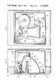
- FIG. 3is a section view taken substantially through a plane indicated by section line 3--3 in FIG. 1.
- FIG. 4is an enlarged partial section view taken substantially through a plane indicated by section line 4--4 in FIG. 1.
- FIG. 5is a transverse section view taken substantially through a plane indicated by section line 5--5 in FIG. 3.
- FIG. 6is a section view taken substantially through a plane indicated by section line 6--6 in FIG. 5.
- FIG. 7is a perspective view of the disassembled transducer associated with the intercom station.
- FIG. 8is a rear perspective view of the front protective plate associated with the intercom station.
- FIG. 1illustrates an intercom station 10 established on a vertical wall 12 of any suitable construction.
- the station location on the exposed side of the wall 12is defined by a front plate 14 to which an enclosure or box 16 is secured extending rearwardly therefrom through an opening 18 in the wall as shown in FIG. 3.
- the front plateis square, and provided with beveled edges 20.
- the platemay be made of a 1/4 inch thick aluminum alloy, for example, having a planar surface with a brushed, anodized natural finish, and fastened to the box by four flat head machine screws 22 threadedly received through inturned tabs 24 projecting inwardly from the box at its open end as shown in FIGS. 3, 5 and 6.
- Threaded openings 28 and 30are also formed in the front plate to mount an LED type monitor lamp 32 and a touch switch 34 as shown in detail in FIG. 4. Also secured to the plate and projecting rearwardly therefrom into the box 16, are a pair of threaded studs 36 through which a transducer assembly 38 is mounted on the front plate and held assembled thereon within the box 16 by nuts 40 as shown in FIGS. 3, 5 and 6. The audible input to and output from the transducer assembly is transmitted through a cluster of closely spaced openings 42 formed in the front plate as shown in FIGS. 1, 5 and 8.
- the electronics associated with the intercom stationis diagrammed in FIG. 2. As shown, signal inputs to the transducer assembly 38 from a speaker line 44 and to the speaker line from the transducer acting as a microphone is applied to the base of a drive transistor 46 to illuminate the monitor lamp 32.
- the touch switch 28controls the operational mode and through a delay circuit 48 controls the duration of an output applied through logic components to the base of a driver transistor 50 to operate relay 52 through which a station identifying lamp 54 at a master station is energized.
- the usual call-in functionsmay be performed at a plurality of such intercom stations 10.
- the electronics diagrammed in FIG. 2,are mounted on a circuit board 56 as shown in FIGS. 3 and 5, and wired to the monitor lamp 32 and touch switch 34 shown in detail in FIG. 4.
- the lamp 32includes a light emitting diode 58 enclosed within a threaded, tubular member or bolt 60 having a hex head portion 62 abutting the rear side of the plate 14.
- the bolt 60is made of a light transmissive or transparent and non-conductive material such as nylon, and the diode 58 is cemented in place by an epoxy cement 64.
- the front end of bolt 60 exposed through plate 14is machined flush with the plate surface.
- the touch switch 34is formed by a non-conductive, tubular machine bolt 66 also made of Nylon, for example, threaded into opening 30.
- a stainless steel machine screw 68electrically connects the switch to the electronics through a terminal lug 70 clamped between the slotted head 72 of screw 68 and the hex head portion 74 of the Nylon bolt 66 abutting the rear side of the front plate 14. The ends of the bolt 66 and screw 68 are machined flush with the exposed surface of the front plate as shown in FIG. 4.
- the transducer assembly 38 shown in FIGS. 3, 5, 6 and 7includes a cylindrical driver unit 76 connected to an exponential, folded horn generally referred to be reference numeral 78.
- the horn configurationincludes four 90° turns to provide the requisite column length and vandal protection for the driver unit 76.
- One input end portion 80 of the horn of smaller cross-sectional passage areaextends axially from the driver unit toward the front plate 14 as shown in FIG. 3.
- End portion 80 of the hornis connected by a first 90° turn to a second diverging passage portion 82 extending closely along the rear side of the plate 14.
- a second 90° turnconnects portion 80 of the horn to a rearwardly extending portion 84 of constant cross-sectional area as more clearly seen in FIG. 5.
- the liner 88supports the circuit board 56 and has two slot formations 94 and 96 through which the studs 36 extend and to which the liner is clamped by the nuts 40 for mounting of the transducer assembly on the front plate as aforementioned.
- the open end 90 of the hornis aligned with the cluster of openings 42 in the front plate from which the driver unit 76 is spaced both rearwardly and laterally so that the input end portion 80 to which the driver unit is connected does not laterally overlap the cluster of openings, as shown.
Landscapes
- Engineering & Computer Science (AREA)
- Signal Processing (AREA)
- Telephone Set Structure (AREA)
Abstract
Description
Claims (7)
Priority Applications (1)
| Application Number | Priority Date | Filing Date | Title |
|---|---|---|---|
| US06/452,094US4518826A (en) | 1982-12-22 | 1982-12-22 | Vandal-proof communication system |
Applications Claiming Priority (1)
| Application Number | Priority Date | Filing Date | Title |
|---|---|---|---|
| US06/452,094US4518826A (en) | 1982-12-22 | 1982-12-22 | Vandal-proof communication system |
Publications (1)
| Publication Number | Publication Date |
|---|---|
| US4518826Atrue US4518826A (en) | 1985-05-21 |
Family
ID=23795009
Family Applications (1)
| Application Number | Title | Priority Date | Filing Date |
|---|---|---|---|
| US06/452,094Expired - Fee RelatedUS4518826A (en) | 1982-12-22 | 1982-12-22 | Vandal-proof communication system |
Country Status (1)
| Country | Link |
|---|---|
| US (1) | US4518826A (en) |
Cited By (30)
| Publication number | Priority date | Publication date | Assignee | Title |
|---|---|---|---|---|
| USD289754S (en) | 1984-02-23 | 1987-05-12 | Electron Corporation (Aust.) Pty. Ltd. | Intercom door answering unit |
| US4851811A (en)* | 1986-07-25 | 1989-07-25 | Xavier Vallat | Communication device for entries of buildings |
| US4974258A (en)* | 1989-07-21 | 1990-11-27 | Raytel, Inc. | Vandal-proof handset for a pay telephone |
| US5086463A (en)* | 1989-10-02 | 1992-02-04 | Vesely Kevin T | Vandal-resistant communications station |
| US5363436A (en)* | 1989-10-02 | 1994-11-08 | Mcmonagle Jr John J | Remotely programmable, vandal-resistant voice communications unit |
| US20030048918A1 (en)* | 2001-09-07 | 2003-03-13 | Dillon Geoffrey M. | Installing a high fidelity sound, voice paging, or music system by mounting an electrical to acoustic transducer inside a wall mounted gang box |
| USD784299S1 (en)* | 2015-04-30 | 2017-04-18 | Shure Acquisition Holdings, Inc. | Array microphone assembly |
| USD865723S1 (en) | 2015-04-30 | 2019-11-05 | Shure Acquisition Holdings, Inc | Array microphone assembly |
| DE102019131859A1 (en)* | 2019-04-04 | 2020-10-08 | Emdion Gmbh | Method for installing a cell communication system and cell communication system |
| USD943552S1 (en) | 2020-05-05 | 2022-02-15 | Shure Acquisition Holdings, Inc. | Audio device |
| USD943558S1 (en) | 2019-11-01 | 2022-02-15 | Shure Acquisition Holdings, Inc. | Housing for ceiling array microphone |
| USD943559S1 (en) | 2019-11-01 | 2022-02-15 | Shure Acquisition Holdings, Inc. | Housing for ceiling array microphone |
| USD944776S1 (en) | 2020-05-05 | 2022-03-01 | Shure Acquisition Holdings, Inc. | Audio device |
| US11297423B2 (en) | 2018-06-15 | 2022-04-05 | Shure Acquisition Holdings, Inc. | Endfire linear array microphone |
| US11297426B2 (en) | 2019-08-23 | 2022-04-05 | Shure Acquisition Holdings, Inc. | One-dimensional array microphone with improved directivity |
| US11302347B2 (en) | 2019-05-31 | 2022-04-12 | Shure Acquisition Holdings, Inc. | Low latency automixer integrated with voice and noise activity detection |
| US11303981B2 (en) | 2019-03-21 | 2022-04-12 | Shure Acquisition Holdings, Inc. | Housings and associated design features for ceiling array microphones |
| US11310596B2 (en) | 2018-09-20 | 2022-04-19 | Shure Acquisition Holdings, Inc. | Adjustable lobe shape for array microphones |
| US11438691B2 (en) | 2019-03-21 | 2022-09-06 | Shure Acquisition Holdings, Inc. | Auto focus, auto focus within regions, and auto placement of beamformed microphone lobes with inhibition functionality |
| US11445294B2 (en) | 2019-05-23 | 2022-09-13 | Shure Acquisition Holdings, Inc. | Steerable speaker array, system, and method for the same |
| US11477327B2 (en) | 2017-01-13 | 2022-10-18 | Shure Acquisition Holdings, Inc. | Post-mixing acoustic echo cancellation systems and methods |
| US11552611B2 (en) | 2020-02-07 | 2023-01-10 | Shure Acquisition Holdings, Inc. | System and method for automatic adjustment of reference gain |
| US11558693B2 (en) | 2019-03-21 | 2023-01-17 | Shure Acquisition Holdings, Inc. | Auto focus, auto focus within regions, and auto placement of beamformed microphone lobes with inhibition and voice activity detection functionality |
| US11678109B2 (en) | 2015-04-30 | 2023-06-13 | Shure Acquisition Holdings, Inc. | Offset cartridge microphones |
| US11706562B2 (en) | 2020-05-29 | 2023-07-18 | Shure Acquisition Holdings, Inc. | Transducer steering and configuration systems and methods using a local positioning system |
| US11785380B2 (en) | 2021-01-28 | 2023-10-10 | Shure Acquisition Holdings, Inc. | Hybrid audio beamforming system |
| US11800281B2 (en) | 2018-06-01 | 2023-10-24 | Shure Acquisition Holdings, Inc. | Pattern-forming microphone array |
| US12028678B2 (en) | 2019-11-01 | 2024-07-02 | Shure Acquisition Holdings, Inc. | Proximity microphone |
| US12250526B2 (en) | 2022-01-07 | 2025-03-11 | Shure Acquisition Holdings, Inc. | Audio beamforming with nulling control system and methods |
| US12289584B2 (en) | 2021-10-04 | 2025-04-29 | Shure Acquisition Holdings, Inc. | Networked automixer systems and methods |
Citations (6)
| Publication number | Priority date | Publication date | Assignee | Title |
|---|---|---|---|---|
| US2578367A (en)* | 1949-07-28 | 1951-12-11 | Bell Telephone Labor Inc | Telephone mounting |
| US3281541A (en)* | 1963-05-13 | 1966-10-25 | Leonard R Learner | Touch sensitive telephone calling apparatus |
| GB1132378A (en)* | 1966-07-02 | 1968-10-30 | Malcolm Neville Shute | Improvements in or relating to telephone equipment |
| US3707607A (en)* | 1970-08-10 | 1972-12-26 | Itt | Hands-free emergency call box |
| US3978479A (en)* | 1975-05-29 | 1976-08-31 | Westinghouse Electric Corporation | Solid state security system |
| US4045629A (en)* | 1974-04-12 | 1977-08-30 | Bassani Ticione S.P.A. | Electrical proximity switch arrangements |
- 1982
- 1982-12-22USUS06/452,094patent/US4518826A/ennot_activeExpired - Fee Related
Patent Citations (6)
| Publication number | Priority date | Publication date | Assignee | Title |
|---|---|---|---|---|
| US2578367A (en)* | 1949-07-28 | 1951-12-11 | Bell Telephone Labor Inc | Telephone mounting |
| US3281541A (en)* | 1963-05-13 | 1966-10-25 | Leonard R Learner | Touch sensitive telephone calling apparatus |
| GB1132378A (en)* | 1966-07-02 | 1968-10-30 | Malcolm Neville Shute | Improvements in or relating to telephone equipment |
| US3707607A (en)* | 1970-08-10 | 1972-12-26 | Itt | Hands-free emergency call box |
| US4045629A (en)* | 1974-04-12 | 1977-08-30 | Bassani Ticione S.P.A. | Electrical proximity switch arrangements |
| US3978479A (en)* | 1975-05-29 | 1976-08-31 | Westinghouse Electric Corporation | Solid state security system |
Cited By (47)
| Publication number | Priority date | Publication date | Assignee | Title |
|---|---|---|---|---|
| USD289754S (en) | 1984-02-23 | 1987-05-12 | Electron Corporation (Aust.) Pty. Ltd. | Intercom door answering unit |
| US4851811A (en)* | 1986-07-25 | 1989-07-25 | Xavier Vallat | Communication device for entries of buildings |
| US4974258A (en)* | 1989-07-21 | 1990-11-27 | Raytel, Inc. | Vandal-proof handset for a pay telephone |
| US5086463A (en)* | 1989-10-02 | 1992-02-04 | Vesely Kevin T | Vandal-resistant communications station |
| US5363436A (en)* | 1989-10-02 | 1994-11-08 | Mcmonagle Jr John J | Remotely programmable, vandal-resistant voice communications unit |
| US5465296A (en)* | 1989-10-02 | 1995-11-07 | Mcmonagle, Jr.; John J. | Remotely programmable, vandal-resistant voice communications unit |
| US5475751A (en)* | 1989-10-02 | 1995-12-12 | Mcmonagle, Jr.; John J. | Remotely programmable, vandal-resistant voice communications unit |
| US5475750A (en)* | 1989-10-02 | 1995-12-12 | Mcmonagle, Jr.; John J. | Vandal-resistant push-button actuator |
| US20030048918A1 (en)* | 2001-09-07 | 2003-03-13 | Dillon Geoffrey M. | Installing a high fidelity sound, voice paging, or music system by mounting an electrical to acoustic transducer inside a wall mounted gang box |
| USD865723S1 (en) | 2015-04-30 | 2019-11-05 | Shure Acquisition Holdings, Inc | Array microphone assembly |
| US11310592B2 (en) | 2015-04-30 | 2022-04-19 | Shure Acquisition Holdings, Inc. | Array microphone system and method of assembling the same |
| USD940116S1 (en) | 2015-04-30 | 2022-01-04 | Shure Acquisition Holdings, Inc. | Array microphone assembly |
| US12262174B2 (en) | 2015-04-30 | 2025-03-25 | Shure Acquisition Holdings, Inc. | Array microphone system and method of assembling the same |
| US11832053B2 (en) | 2015-04-30 | 2023-11-28 | Shure Acquisition Holdings, Inc. | Array microphone system and method of assembling the same |
| US11678109B2 (en) | 2015-04-30 | 2023-06-13 | Shure Acquisition Holdings, Inc. | Offset cartridge microphones |
| USD784299S1 (en)* | 2015-04-30 | 2017-04-18 | Shure Acquisition Holdings, Inc. | Array microphone assembly |
| US12309326B2 (en) | 2017-01-13 | 2025-05-20 | Shure Acquisition Holdings, Inc. | Post-mixing acoustic echo cancellation systems and methods |
| US11477327B2 (en) | 2017-01-13 | 2022-10-18 | Shure Acquisition Holdings, Inc. | Post-mixing acoustic echo cancellation systems and methods |
| US11800281B2 (en) | 2018-06-01 | 2023-10-24 | Shure Acquisition Holdings, Inc. | Pattern-forming microphone array |
| US11770650B2 (en) | 2018-06-15 | 2023-09-26 | Shure Acquisition Holdings, Inc. | Endfire linear array microphone |
| US11297423B2 (en) | 2018-06-15 | 2022-04-05 | Shure Acquisition Holdings, Inc. | Endfire linear array microphone |
| US11310596B2 (en) | 2018-09-20 | 2022-04-19 | Shure Acquisition Holdings, Inc. | Adjustable lobe shape for array microphones |
| US11778368B2 (en) | 2019-03-21 | 2023-10-03 | Shure Acquisition Holdings, Inc. | Auto focus, auto focus within regions, and auto placement of beamformed microphone lobes with inhibition functionality |
| US11438691B2 (en) | 2019-03-21 | 2022-09-06 | Shure Acquisition Holdings, Inc. | Auto focus, auto focus within regions, and auto placement of beamformed microphone lobes with inhibition functionality |
| US12425766B2 (en) | 2019-03-21 | 2025-09-23 | Shure Acquisition Holdings, Inc. | Auto focus, auto focus within regions, and auto placement of beamformed microphone lobes with inhibition and voice activity detection functionality |
| US11558693B2 (en) | 2019-03-21 | 2023-01-17 | Shure Acquisition Holdings, Inc. | Auto focus, auto focus within regions, and auto placement of beamformed microphone lobes with inhibition and voice activity detection functionality |
| US11303981B2 (en) | 2019-03-21 | 2022-04-12 | Shure Acquisition Holdings, Inc. | Housings and associated design features for ceiling array microphones |
| US12284479B2 (en) | 2019-03-21 | 2025-04-22 | Shure Acquisition Holdings, Inc. | Auto focus, auto focus within regions, and auto placement of beamformed microphone lobes with inhibition functionality |
| DE102019131859B4 (en) | 2019-04-04 | 2023-06-29 | Emdion Gmbh | Method for installing a cell communication system and cell communication system |
| DE102019131859A1 (en)* | 2019-04-04 | 2020-10-08 | Emdion Gmbh | Method for installing a cell communication system and cell communication system |
| US11445294B2 (en) | 2019-05-23 | 2022-09-13 | Shure Acquisition Holdings, Inc. | Steerable speaker array, system, and method for the same |
| US11800280B2 (en) | 2019-05-23 | 2023-10-24 | Shure Acquisition Holdings, Inc. | Steerable speaker array, system and method for the same |
| US11302347B2 (en) | 2019-05-31 | 2022-04-12 | Shure Acquisition Holdings, Inc. | Low latency automixer integrated with voice and noise activity detection |
| US11688418B2 (en) | 2019-05-31 | 2023-06-27 | Shure Acquisition Holdings, Inc. | Low latency automixer integrated with voice and noise activity detection |
| US11297426B2 (en) | 2019-08-23 | 2022-04-05 | Shure Acquisition Holdings, Inc. | One-dimensional array microphone with improved directivity |
| US11750972B2 (en) | 2019-08-23 | 2023-09-05 | Shure Acquisition Holdings, Inc. | One-dimensional array microphone with improved directivity |
| USD943559S1 (en) | 2019-11-01 | 2022-02-15 | Shure Acquisition Holdings, Inc. | Housing for ceiling array microphone |
| USD943558S1 (en) | 2019-11-01 | 2022-02-15 | Shure Acquisition Holdings, Inc. | Housing for ceiling array microphone |
| US12028678B2 (en) | 2019-11-01 | 2024-07-02 | Shure Acquisition Holdings, Inc. | Proximity microphone |
| US11552611B2 (en) | 2020-02-07 | 2023-01-10 | Shure Acquisition Holdings, Inc. | System and method for automatic adjustment of reference gain |
| USD944776S1 (en) | 2020-05-05 | 2022-03-01 | Shure Acquisition Holdings, Inc. | Audio device |
| USD943552S1 (en) | 2020-05-05 | 2022-02-15 | Shure Acquisition Holdings, Inc. | Audio device |
| US12149886B2 (en) | 2020-05-29 | 2024-11-19 | Shure Acquisition Holdings, Inc. | Transducer steering and configuration systems and methods using a local positioning system |
| US11706562B2 (en) | 2020-05-29 | 2023-07-18 | Shure Acquisition Holdings, Inc. | Transducer steering and configuration systems and methods using a local positioning system |
| US11785380B2 (en) | 2021-01-28 | 2023-10-10 | Shure Acquisition Holdings, Inc. | Hybrid audio beamforming system |
| US12289584B2 (en) | 2021-10-04 | 2025-04-29 | Shure Acquisition Holdings, Inc. | Networked automixer systems and methods |
| US12250526B2 (en) | 2022-01-07 | 2025-03-11 | Shure Acquisition Holdings, Inc. | Audio beamforming with nulling control system and methods |
Similar Documents
| Publication | Publication Date | Title |
|---|---|---|
| US4518826A (en) | Vandal-proof communication system | |
| CA2164562A1 (en) | Universal mounting plate for audible-visual alarms | |
| US6271763B1 (en) | Audible and audible-visible alarms with interchangeable cover | |
| US5082083A (en) | Structure wall mounted speaker assembly | |
| ATE176362T1 (en) | ELECTRICALLY COMPENSATED CONNECTOR ARRANGEMENT | |
| US5073842A (en) | Anti-theft illuminated display device | |
| KR930002221A (en) | Display member for elevator | |
| GB2262406A (en) | Improvements in and relating to combined television and video devices | |
| US2282384A (en) | Flush wall mounting for radio units | |
| US3155771A (en) | Electronic chassis mounting bracket | |
| CA1233550A (en) | Vandal-proof communication system | |
| DE59406644D1 (en) | Antenna device for electronic anti-theft systems | |
| US3892930A (en) | Loudspeaker enclosure | |
| US6180859B1 (en) | Panel assembly for electronic keyboard musical instrument | |
| US20040075554A1 (en) | Luggage location and identification system | |
| US3739368A (en) | Starter gun attachment | |
| US2386738A (en) | Chime signal | |
| US4203383A (en) | Burglar alarm | |
| US4813192A (en) | Door assembly | |
| JPS63238751A (en) | Inter-indoor communication annunciator | |
| US4508458A (en) | Electric clock movement, particularly a quartz clock movement | |
| GB1182410A (en) | Improvements in or relating to a Mechanically-actuated Warning Device | |
| JPH0686424A (en) | Connection and attachment fitting | |
| CN209199278U (en) | A kind of phonetic alarm | |
| KR940000152Y1 (en) | Burglar alarm |
Legal Events
| Date | Code | Title | Description |
|---|---|---|---|
| AS | Assignment | Owner name:MOUNTAIN SYSTEMS, INC., A NEW MEXICO CORP. Free format text:ASSIGNMENT OF ASSIGNORS INTEREST.;ASSIGNORS:CAUDILL, EDDIE T.;CAUDILL, RICHARD T.;CONLEY, LYLE N.;REEL/FRAME:004078/0498 Effective date:19821206 Owner name:MOUNTAIN SYSTEMS, INC., A NEW MEXICO CORP., DISTRI Free format text:ASSIGNMENT OF ASSIGNORS INTEREST;ASSIGNORS:CAUDILL, EDDIE T.;CAUDILL, RICHARD T.;CONLEY, LYLE N.;REEL/FRAME:004078/0498 Effective date:19821206 | |
| FEPP | Fee payment procedure | Free format text:PAYOR NUMBER ASSIGNED (ORIGINAL EVENT CODE: ASPN); ENTITY STATUS OF PATENT OWNER: SMALL ENTITY | |
| FPAY | Fee payment | Year of fee payment:4 | |
| FEPP | Fee payment procedure | Free format text:PAYOR NUMBER ASSIGNED (ORIGINAL EVENT CODE: ASPN); ENTITY STATUS OF PATENT OWNER: SMALL ENTITY | |
| FPAY | Fee payment | Year of fee payment:8 | |
| SULP | Surcharge for late payment | ||
| REMI | Maintenance fee reminder mailed | ||
| LAPS | Lapse for failure to pay maintenance fees | ||
| FP | Lapsed due to failure to pay maintenance fee | Effective date:19970521 | |
| STCH | Information on status: patent discontinuation | Free format text:PATENT EXPIRED DUE TO NONPAYMENT OF MAINTENANCE FEES UNDER 37 CFR 1.362 |