US4516437A - Microsample handling apparatus - Google Patents
Microsample handling apparatusDownload PDFInfo
- Publication number
- US4516437A US4516437AUS06/478,134US47813483AUS4516437AUS 4516437 AUS4516437 AUS 4516437AUS 47813483 AUS47813483 AUS 47813483AUS 4516437 AUS4516437 AUS 4516437A
- Authority
- US
- United States
- Prior art keywords
- probe
- cleaning chamber
- cleaning
- probe means
- flow
- Prior art date
- Legal status (The legal status is an assumption and is not a legal conclusion. Google has not performed a legal analysis and makes no representation as to the accuracy of the status listed.)
- Expired - Lifetime
Links
- 239000000523sampleSubstances0.000claimsabstractdescription184
- 238000004140cleaningMethods0.000claimsabstractdescription145
- 239000012530fluidSubstances0.000claimsabstractdescription71
- 238000000034methodMethods0.000claimsabstractdescription26
- 238000005406washingMethods0.000claimsdescription37
- 238000001035dryingMethods0.000claimsdescription11
- 230000005499meniscusEffects0.000claimsdescription8
- 239000000356contaminantSubstances0.000claimsdescription4
- 238000007599dischargingMethods0.000claims1
- 230000007246mechanismEffects0.000abstractdescription11
- 238000005070samplingMethods0.000description12
- 238000011109contaminationMethods0.000description3
- 238000013461designMethods0.000description3
- 239000007788liquidSubstances0.000description3
- 229920003023plasticPolymers0.000description3
- 239000004033plasticSubstances0.000description3
- 238000012545processingMethods0.000description3
- 239000002699waste materialSubstances0.000description3
- 229920006362Teflon®Polymers0.000description2
- 239000000463materialSubstances0.000description2
- 238000012986modificationMethods0.000description2
- 230000004048modificationEffects0.000description2
- 238000012546transferMethods0.000description2
- VVQNEPGJFQJSBK-UHFFFAOYSA-NMethyl methacrylateChemical compoundCOC(=O)C(C)=CVVQNEPGJFQJSBK-UHFFFAOYSA-N0.000description1
- 229920005372Plexiglas®Polymers0.000description1
- 239000004809TeflonSubstances0.000description1
- NIXOWILDQLNWCW-UHFFFAOYSA-Nacrylic acid groupChemical groupC(C=C)(=O)ONIXOWILDQLNWCW-UHFFFAOYSA-N0.000description1
- 239000008280bloodSubstances0.000description1
- 210000004369bloodAnatomy0.000description1
- 230000001112coagulating effectEffects0.000description1
- 238000010276constructionMethods0.000description1
- 238000006073displacement reactionMethods0.000description1
- 238000011065in-situ storageMethods0.000description1
- 238000011835investigationMethods0.000description1
- 238000007789sealingMethods0.000description1
- 239000010935stainless steelSubstances0.000description1
- BFKJFAAPBSQJPD-UHFFFAOYSA-NtetrafluoroetheneChemical compoundFC(F)=C(F)FBFKJFAAPBSQJPD-UHFFFAOYSA-N0.000description1
Images


Classifications
- G—PHYSICS
- G01—MEASURING; TESTING
- G01N—INVESTIGATING OR ANALYSING MATERIALS BY DETERMINING THEIR CHEMICAL OR PHYSICAL PROPERTIES
- G01N35/00—Automatic analysis not limited to methods or materials provided for in any single one of groups G01N1/00 - G01N33/00; Handling materials therefor
- G01N35/10—Devices for transferring samples or any liquids to, in, or from, the analysis apparatus, e.g. suction devices, injection devices
- G01N35/1004—Cleaning sample transfer devices
- G—PHYSICS
- G01—MEASURING; TESTING
- G01N—INVESTIGATING OR ANALYSING MATERIALS BY DETERMINING THEIR CHEMICAL OR PHYSICAL PROPERTIES
- G01N35/00—Automatic analysis not limited to methods or materials provided for in any single one of groups G01N1/00 - G01N33/00; Handling materials therefor
- G01N35/10—Devices for transferring samples or any liquids to, in, or from, the analysis apparatus, e.g. suction devices, injection devices
- G01N35/1081—Devices for transferring samples or any liquids to, in, or from, the analysis apparatus, e.g. suction devices, injection devices characterised by the means for relatively moving the transfer device and the containers in an horizontal plane
- G01N35/1083—Devices for transferring samples or any liquids to, in, or from, the analysis apparatus, e.g. suction devices, injection devices characterised by the means for relatively moving the transfer device and the containers in an horizontal plane with one horizontal degree of freedom
Definitions
- the inventionrelates to an apparatus and method for cleaning a probe between fluid sampling operations of the probe. More particularly, this invention concerns the external washing and drying of a probe preparatory to its use with another sample.
- sample analysis and cell sorting systemsit is necessary to virtually eliminate sample contamination, while rapidly and repetitively sampling successive samples, particularly where a large number of different samples are to be processed automatically.
- the apparatusshould be as simple and compact as possible, as well as perform both sampling and cleaning in situ, that is in the same lateral position.
- Some large size sample analysis and cell sorting systemssuch as the DACOSTM Chemistry System, manufactured by Coulter Electronics, Inc., Hialeah, Fla., utilize transfer mechanisms to laterally move an axially movable, vertically oriented, sampling probe between sampling operations for cleaning to a closed bottom cleaning station.
- Another object of the inventionis to provide an improved microsample handling apparatus and method for externally cleaning, washing and drying, its sample probe.
- a further object of the inventionis to provide improved microsample handling apparatus and method for cleaning its sample probe whereby sample contamination is virtually eliminated.
- a still further object of the inventionis to provide a simple and compact microsample handling apparatus and method for cleaning its sample probe.
- Still another object of the inventionis to provide an improved microsample handling apparatus and method for cleaning its sample probe without the necessity of any lateral movement between the probe and its cleaning station.
- Another object of the inventionis to provide an improved microsample handling apparatus and method for cleaning a sample probe wherein said apparatus remains laterally fixed in place when the cleaning is performed after sampling.
- a further object of the inventionis to provide a simple and compact microsample handling apparatus and method for cleaning a sample probe wherein said apparatus remains laterally fixed in place when said cleaning is performed after sampling.
- a still further object of the inventionis to provide an open ended microsampling handling apparatus and method for cleaning a sample probe which does not require an elaborate sample feeding mechanism.
- Another object of the inventionis to provide an open ended microsampling handling apparatus and method for cleaning a sample probe which is ideally suited for automatically processing a large number of open samples.
- the apparatuscomprises the probe means for aspirating a sample and a cleaning mechanism having a passageway within which the probe means is movable.
- the passagewayhas a cleaning chamber having opposite ends, one end being open to the atmosphere and proximate to the sample.
- the cleaning mechanismfurther includes a fluid directing means and two vacuum applying means, said vacuum applying means disposed at opposite ends of said chamber and said fluid directing means disposed between them.
- the fluid directing meansdirects a wash fluid against said probe means during a cleaning mode and said vacuum applying means removes the wash fluid, prevents exiting of the wash fluid and drys the probe means, the later two by permitting gas from the atmosphere to flow into said cleaning chamber.
- the method of cleaning the probe means within the cleaning chamber of the cleaning mechanism, said cleaning chamber which has a first open end and a second end, and a plurality of cleaning portscomprises the step of: moving the probe means to be cleaned within said cleaning chamber and externally: directing a flow of washing fluid against said probe means, drawing said flow of washing fluid past said probe means, and drawing a flow of gas from the atmosphere past said probe tip when it is within said cleaning chamber.
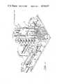
- FIG. 1is a perceptive view of the microsample handling apparatus of the invention and a partial view of a microsample handling system of which it is a part with its tubing and connections fragmentally shown;
- FIG. 2is a side elevation view, partly in section, of the microsample handling apparatus shown in FIG. 1, but without its probe;
- FIG. 3is a bottom elevation view of the embodiment of FIG. 2;
- FIG. 4is a vertical section on line 4--4 of FIG. 2;
- FIG. 5is a horizontal section on line 5--5 of FIG. 4 and a Y-connector assembly coupled to its fitting;
- FIG. 6is an enlarged, simplified, view of FIG. 4 with the probe being shown in its sampling position and, in a phantom view, in its retracted position.
- a microsample handling apparatus 10is constructed in accordance with a preferred embodiment of the invention which is part of a microsample handling system 12 (partially shown).
- the microsample handling system 12operates with cell analyzing and sorting systems for biomedical investigation, such as a COULTER® EPICS®V System, described in its PG,6 product reference manual of February 1982, part number 4235066B, available from Coulter Electronics, Inc., Hialeah, Fla., and is incorporated herein, by reference, and can replace the viable sample handling system subcomponent thereof as the source of the sample into said EPICS®V System.
- COULTERis the registered trademark No. 995,825 of Coulter Electronics, Inc., Hialeah, Fla.
- EPICSis the registered trademark No. 1,175,973 of Coulter Corporation, Hialeah, Fla.
- the microsample handling system 12comprises a carrier assembly 14, which is movable forwards and backwards, as shown by the arrows X, by conventional means such as stepper motors (not shown).
- the microsample handling apparatus 10is fixedly mounted at the front portion of the carrier assembly 14, which apparatus includes a probe means, aspirator or probe 16.
- This probe 16is both axially movable within and movable together with a cleaning mechanism or station 18, described in detail hereinafter.
- the upper end of the probe 16is fixedly connected to a horizontal extension arm 20 seated on the top of the carrier assembly 14 and is axially movable by said arm 20 within the cleaning station 18.
- the other end of the arm 20is vertically movable by conventional pressure actuated means, including an air cylinder 22 which has an air fitting 24 connected to a conventional, controlled source of air pressure (not shown).
- air cylinder 22which has an air fitting 24 connected to a conventional, controlled source of air pressure (not shown).
- samplesare taken from a sequence of wells in a MICROTITER® plate or sample container 26, preferably with ninety-six wells, which plate 26 is laterally moved under the probe 16, forwards and backwards, as shown by arrows Y, on a holder 28 by conventional means, such as a stepper motor (not shown).
- a manual modethe microsample handling apparatus 10 is moved forward in the X direction to take a sample from a single sample or culture tube (not shown) held by an operator and properly positioned below the probe 16. Sampling and cleaning, in both the automatic and the manual mode, are performed while the microsample handling apparatus 10 remains laterally fixed in place, as explained in detail hereinafter.
- the microsample handling apparatus 10comprises the probe means 16, which is axially disposed within the cleaning station 18, for aspirating a sample.
- Probe 16includes a probe tip 30 and is of conventional single tube design, preferably of corrosion resistant steel, type 316 and of half hard temper, with an aspirating opening 32 at its end. Its exterior is preferably TEFLON® coated, 0.002 ⁇ 0.003 thick, in inches. (TEFLON is a registered trademark of Du Pont de Nemours, E.
- the cleaning station or means 18includes a rectangular shaped, elongated, carrier member 34 having an upper bore 36 axially extending through an upper portion of the carrier member 34 and communicating with a concentrically disposed lower bore 38 of slightly greater diameter, which axially extends through a lower portion of the carrier member 34.
- a generally cylindrical manifold 40preferably formed of acrylic PLEXIGLASS® plastic material, is connected in sealing engagement in the lower bore 38 formed in carrier member 34 and includes, as a part of its interior wall, an internal passageway 42 having walls 43 which define or form a cleaning chamber 44.
- bushings 46Disposed at the upper and lower ends of the upper bore 36 are bushings 46 to properly locate and guide probe 16 within the passageway 42 and within which it is axially movable.
- Cleaning chamber 44has opposite ends, lower and upper ends, 48 and 50, respectively, and a plurality of cleaning ports formed in the internal passageway 42, including a pair of opposing upper cleaning ports 52, center cleaning ports 54, preferably four in number each of which is equally spaced around the central portion of the periphery of the passageway 42, and a pair of opposing lower cleaning ports 56.
- the lower or first end 48 of the cleaning chamber 44is open to the atmosphere and is disposed proximate to the sample.
- the other end, upper or second end 50is disposed distally from the sample.
- first and fourth means 58 and 59Communicating with the central portion of the cleaning chamber 44, through the center ports 54, are first and fourth means 58 and 59, respectively, including four center side passageways 60, each directed radially and inwardly toward the center axis of the internal passageway 42, and having their external ends opening into an annular chamber 62 formed in the exterior wall of the manifold 40, which in turn opens into a single center side bore 64, which has a fluid fitting 66 inserted therein.
- the lower portion of the cleaning chamber 44communicates through said lower cleaning ports 56 with a second means 68, including, preferably, a pair of lower side passageways 70 disposed at the mouth 71 of the open-ended chamber 44.
- Each of the lower side passageways 70is directed angularly, preferably sixty degrees from the axis of the chamber 44, and radially inwardly toward the center axis of the internal passageway 42, and having each of their external ends opening directly into a lower side bore 72, which has a fluid fitting 74 inserted therein.
- the upper portion of the cleaning chamber 44communicates through the upper ports 52 with a third means 76, including, preferably, a pair of upper side passageways 78 disposed at the upper end 50 of said chamber 44, each of said upper side passageways 78 are directed radially and inwardly toward the center axis of the internal passageway 42 and having each of their external ends opening directly into a upper side bore 80, which has a fluid fitting 82 inserted therein.
- the first and fourth means 58 and 59respectively, further include, in common, a conduit means or line 84, preferably of clear plastic tubing, connected at one end to the fluid fitting 66 and at its other end to a branch portion 86 of a Y-connector 88.
- the first means 58additionally includes a stem 90 of Y-connector 88 which is coupled to a washing fluid source shown diagrammatically by an arrow W.
- the fourth means 59additionally includes a stem 92 of the Y-connector 88, which is coupled to a vacuum drain shown diagrammatically by an arrow V C .
- the second means 68further includes conduit means (not shown) connected at one end to both fluid fittings 74, has its other end to the vacuum drain and is shown diagrammatically by arrows V L .
- the third means 76further includes conduit means (not shown) connected at one end to both fluid fittings 82, and has its other end coupled to the vacuum drain and is shown diagrammatically by arrows V U .
- portsare specified as being either “close” or “open”, or “closed” or “opened”, or the like, such status refers to a source of a negative pressure (a vacuum), wash fluid, or a flow of air and/or liquid, or the like being either prevented or permitted to flow past or be gated through said ports through controlled valves, such as pinch valves, under the control of a controlling means, such as a microprocessor.
- a negative pressurea vacuum
- wash fluidor a flow of air and/or liquid, or the like
- the lower ports 56are opened to the vaccum V L , and remain open until the probe 16 enters the sample container 26, the probe's down position, at which time each of the three series of cleaning ports, upper ports 52, center ports 54, and lower ports 56, are sequentially opened and closed in the aforesaid order, to air dry the probe 16 by drawing into the cleaning chamber 44, through its mouth, a flow of air or gas from the atmosphere through the opened ports, all prior to aspiration of the sample.
- the first part of a cleaning cycle or modeis initiated to clean the outside of the probe 16 by first reopening lower ports 56 to the vacuum V C and then directing a flow of washing fluid W, such as ISOTON® liquid, against the exterior of the probe 16 through opened center ports 54, while maintaining the lower ports 56 open.
- washing fluid Wsuch as ISOTON® liquid
- the probe 16then is instructed to move to its up position, which initiates the second part of the cleaning mode, and, as it starts to move upwards, the flow of washing fluid W is continued for an appropriate period of time.
- the probe 16reaches its retracted position, the following sequence occurs: the upper ports 52 are open to the vacuum V U , the lower ports 56 are closed, the center ports 54 are closed to the wash fluid while simultaneously these same center ports 54 are opened to the vacuum V C , and then both the center and upper ports 54 and 52, respectively, are closed to their vacuums V C and V U , respectively. Accordingly during the first part of this cleaning mode, when the probe 16 is in its down position, the whole upper outside portion of the probe 16 is washed and dryed in the cleaning chamber 44.
- both series of center and upper ports 54 and 52respectively, now remove any remaining wash liquid W and sample contaminants from the outside of the probe 16 and its passageway 42 and then dry them by drawing into the upper portion of the cleaning chamber 44, through its mouth 71, a flow of air from the atmosphere through both the opened ports 54 and 52. After a desired interval sufficient for such drying, both series of open ports 52 and 54 are closed.
- This cleaning modeis initiated very shortly after the sample is aspirated and while the sample is still fresh, so as to decrease the possibility of the sample, when it constitutes blood, coagulating on the tip 30, or any other portion of the probe 16, or in the passageway 42, or at the mouth 71 of the cleaning chamber 44, which makes subsequent removal more difficult.
- the probe 16While the probe 16 is still in its retracted or up position, the sample is delivered to the associated cell analyzing and sorting system. Then its interior is flushed by introducing washing fluid therethrough under pressure and drawing the washing fluid through the lower and center ports 56 and 54, respectively, which are opened to vacuum V L and V C , respectively, for such purpose. Then the same cleaning cycle or mode, described above, is repeated, except that all the sequence of steps are performed while the probe 16 remains in its retracted or up position, thereby cleaning and drying only the probe tip 30.
- a mixing cycleis initiated prior to aspiration, which preferably includes aspiration of a small amount of sample into the probe, preferably 100 ul, then delivering or returning it back to the same well of the sample container 26, and repeating this procedure another two times. It should also be noted that there is an intersurface flow of washing fluid between or along the walls 43 of said cleaning chamber 44 and the outside or exterior wall of said probe 16 during the period of time the wash fluid is directed against the probe 16 and drawn past it by the vacuums V L , V C and V U .
- the vacuum at the vacuum pump(not shown) is approximately ten PSI and the vacuum at the fittings 76, 66 and 82, is greater than five PSI and the wash fluid is pressurized to a similar, positive, value.
- an improved microsample handling apparatus and methodfor cleaning, washing and drying a sample probe 16, particularly its exterior, which apparatus 10 is both simple, in design and operation, and compact and wherein sample contamination is virtually eliminated.
- the apparatus 10In operation there is no relative lateral movement between the probe 16 and its cleaning station 18; also the probe 16, is contrained to vertical displacement.
- the apparatus 10is fixed in place laterally and is ideally suited for automatically processing a large number of open samples.
- microsample handling apparatus 10can be molded or machined or otherwise formed from plastic or other convenient material.
Landscapes
- Physics & Mathematics (AREA)
- Health & Medical Sciences (AREA)
- Life Sciences & Earth Sciences (AREA)
- Chemical & Material Sciences (AREA)
- Analytical Chemistry (AREA)
- Biochemistry (AREA)
- General Health & Medical Sciences (AREA)
- General Physics & Mathematics (AREA)
- Immunology (AREA)
- Pathology (AREA)
- Automatic Analysis And Handling Materials Therefor (AREA)
- Sampling And Sample Adjustment (AREA)
Abstract
Description
______________________________________ PORT DIAMETERS Lower (56) Center (54) Upper (52) ______________________________________ .086 .013 .086 ______________________________________ CLEANING CHAMBER (44) Length Diameter ______________________________________ 1.68 .090 ______________________________________ Distance from Mouth (71) to Center of the Ports Lower (56) Center (54) Upper (52) ______________________________________ 0.100 0.860 1.460 ______________________________________ PROBE (16) Length Outside Diameter Inside Diameter ______________________________________ 8.07 .062 ± .001 .010 ± .001 ______________________________________
Claims (20)
Priority Applications (1)
| Application Number | Priority Date | Filing Date | Title |
|---|---|---|---|
| US06/478,134US4516437A (en) | 1983-03-23 | 1983-03-23 | Microsample handling apparatus |
Applications Claiming Priority (1)
| Application Number | Priority Date | Filing Date | Title |
|---|---|---|---|
| US06/478,134US4516437A (en) | 1983-03-23 | 1983-03-23 | Microsample handling apparatus |
Publications (1)
| Publication Number | Publication Date |
|---|---|
| US4516437Atrue US4516437A (en) | 1985-05-14 |
Family
ID=23898668
Family Applications (1)
| Application Number | Title | Priority Date | Filing Date |
|---|---|---|---|
| US06/478,134Expired - LifetimeUS4516437A (en) | 1983-03-23 | 1983-03-23 | Microsample handling apparatus |
Country Status (1)
| Country | Link |
|---|---|
| US (1) | US4516437A (en) |
Cited By (28)
| Publication number | Priority date | Publication date | Assignee | Title |
|---|---|---|---|---|
| US4621534A (en)* | 1983-09-14 | 1986-11-11 | Carlo Erba Strumentazione S.P.A. | Automatic sample apparatus, valve and sampling method |
| JPS6325559A (en)* | 1986-06-23 | 1988-02-03 | イー・アイ・デュポン・ドゥ・ヌムール・アンド・カンパニー | Liquid distributor |
| FR2614422A1 (en)* | 1987-04-24 | 1988-10-28 | Smithkline Diagnostics Inc | ENZYMATIC ELECTRODE AND PERFECTED ELECTRODE MODULE AND METHOD OF USE |
| US4799393A (en)* | 1985-09-03 | 1989-01-24 | Technicon Instruments Corporation | Combined closed and open tube sampling apparatus and method |
| US4989623A (en)* | 1989-12-01 | 1991-02-05 | Akzo N.V. | Apparatus and method for cleaning reagent delivery probes |
| US5133373A (en)* | 1989-12-01 | 1992-07-28 | Akzo N.V. | Apparatus and method for cleaning reagent delivery probes |
| EP0602802A1 (en)* | 1992-12-17 | 1994-06-22 | Beckman Instruments, Inc. | Fluid probe washing apparatus and method |
| US5334353A (en)* | 1993-02-03 | 1994-08-02 | Blattner Frederick R | Micropipette device |
| US5474744A (en)* | 1993-10-28 | 1995-12-12 | Hoffmann-La Roche Inc. | Automatic pipetting device with cleaning mechanism |
| US5525515A (en)* | 1993-02-03 | 1996-06-11 | Blattner; Frederick R. | Process of handling liquids in an automated liquid handling apparatus |
| WO1997001750A1 (en)* | 1995-06-29 | 1997-01-16 | Coulter International Corp. | Apparatus for cleaning a fluid sample probe |
| US5646046A (en)* | 1989-12-01 | 1997-07-08 | Akzo Nobel N.V. | Method and instrument for automatically performing analysis relating to thrombosis and hemostasis |
| US5730938A (en)* | 1995-08-09 | 1998-03-24 | Bio-Chem Laboratory Systems, Inc. | Chemistry analyzer |
| WO1998021560A1 (en)* | 1996-11-15 | 1998-05-22 | Biochem Immunosystems Inc. | Open vial aspirator and probe washer |
| US5827744A (en)* | 1995-11-06 | 1998-10-27 | Dade International Inc. | Method and apparatus for cleaning a liquid dispensing probe |
| JP2828711B2 (en) | 1988-10-21 | 1998-11-25 | テクニコン・インストゥルメンツ・コーポレーション | Method and apparatus for supplying sample liquid |
| US6422248B1 (en)* | 1996-03-18 | 2002-07-23 | Roche Diagnostics Gmbh | Device for cleaning pipette needles or stirrers |
| US20020142288A1 (en)* | 2001-02-16 | 2002-10-03 | Kaultkiewicz Peter E. | Auto-sampler for treatment or pretreatment of sample multicellular organisms for a large particle sorting flow cytometer |
| US6551557B1 (en)* | 1998-07-07 | 2003-04-22 | Cartesian Technologies, Inc. | Tip design and random access array for microfluidic transfer |
| US20040096368A1 (en)* | 2002-06-28 | 2004-05-20 | Igen International, Inc. | Assay systems and components |
| US20050279387A1 (en)* | 2004-06-17 | 2005-12-22 | Blackwell Gregory A | Probe washing cups and methods |
| US20060179946A1 (en)* | 2005-02-01 | 2006-08-17 | Beckman Coulter, Inc. | Method and apparatus for washing a probe or the like using ultrasonic energy |
| US20080302393A1 (en)* | 2007-05-11 | 2008-12-11 | Bio-Rad Laboratories, Inc. | Wash ring assembly and method of use |
| CN108931415A (en)* | 2017-05-23 | 2018-12-04 | 北京诚智光辉科技有限公司 | Sectioning cells with wiper mechanism dye all-in-one machine |
| US20190041414A1 (en)* | 2017-08-01 | 2019-02-07 | Euroimmun Medizinische Labordiagnostika Ag | Apparatus and method for cleaning pipetting needles |
| WO2019140549A1 (en)* | 2018-01-16 | 2019-07-25 | 深圳迎凯生物科技有限公司 | Sampling needle cleaning device |
| US10786835B2 (en)* | 2015-06-29 | 2020-09-29 | Hitachi High-Tech Corporation | Ultrasonic cleaner and automatic analyzer using the same |
| US11529656B2 (en)* | 2016-05-11 | 2022-12-20 | Siemens Healthcare Diagnostics Inc. | Probe wash station for analytical instrumentation |
Citations (7)
| Publication number | Priority date | Publication date | Assignee | Title |
|---|---|---|---|---|
| US3266322A (en)* | 1964-06-15 | 1966-08-16 | Technicon Instr | Automatic liquid sample supply and wash apparatus for automatic analysis system |
| US3719086A (en)* | 1971-01-12 | 1973-03-06 | Damon Corp | Liquids sampler with probe-bathing chamber |
| US3911749A (en)* | 1973-10-16 | 1975-10-14 | Chemlab Mfg Ltd | Sampling probes |
| US4064886A (en)* | 1975-11-20 | 1977-12-27 | Riwoplan Medizin-Technische Einrichtungs-Gesellschaft Mbh | Apparatus for cleansing endoscopes |
| US4166305A (en)* | 1976-12-10 | 1979-09-04 | Projectus Industriprodukter Aktiebolag | Device for washing machine parts |
| US4217780A (en)* | 1979-07-09 | 1980-08-19 | Ortho Diagnostic, Inc. | Automated, self-cleaning fluid sampling apparatus |
| US4311484A (en)* | 1980-04-09 | 1982-01-19 | Cortex Research Corporation | Specimen sampling apparatus |
- 1983
- 1983-03-23USUS06/478,134patent/US4516437A/ennot_activeExpired - Lifetime
Patent Citations (7)
| Publication number | Priority date | Publication date | Assignee | Title |
|---|---|---|---|---|
| US3266322A (en)* | 1964-06-15 | 1966-08-16 | Technicon Instr | Automatic liquid sample supply and wash apparatus for automatic analysis system |
| US3719086A (en)* | 1971-01-12 | 1973-03-06 | Damon Corp | Liquids sampler with probe-bathing chamber |
| US3911749A (en)* | 1973-10-16 | 1975-10-14 | Chemlab Mfg Ltd | Sampling probes |
| US4064886A (en)* | 1975-11-20 | 1977-12-27 | Riwoplan Medizin-Technische Einrichtungs-Gesellschaft Mbh | Apparatus for cleansing endoscopes |
| US4166305A (en)* | 1976-12-10 | 1979-09-04 | Projectus Industriprodukter Aktiebolag | Device for washing machine parts |
| US4217780A (en)* | 1979-07-09 | 1980-08-19 | Ortho Diagnostic, Inc. | Automated, self-cleaning fluid sampling apparatus |
| US4311484A (en)* | 1980-04-09 | 1982-01-19 | Cortex Research Corporation | Specimen sampling apparatus |
Cited By (48)
| Publication number | Priority date | Publication date | Assignee | Title |
|---|---|---|---|---|
| US4621534A (en)* | 1983-09-14 | 1986-11-11 | Carlo Erba Strumentazione S.P.A. | Automatic sample apparatus, valve and sampling method |
| US4799393A (en)* | 1985-09-03 | 1989-01-24 | Technicon Instruments Corporation | Combined closed and open tube sampling apparatus and method |
| JPS6325559A (en)* | 1986-06-23 | 1988-02-03 | イー・アイ・デュポン・ドゥ・ヌムール・アンド・カンパニー | Liquid distributor |
| EP0251087A3 (en)* | 1986-06-23 | 1989-03-15 | E.I. Du Pont De Nemours And Company | Movable cleaning assembly for an aspirating needle |
| FR2614422A1 (en)* | 1987-04-24 | 1988-10-28 | Smithkline Diagnostics Inc | ENZYMATIC ELECTRODE AND PERFECTED ELECTRODE MODULE AND METHOD OF USE |
| AU629767B2 (en)* | 1987-11-20 | 1992-10-08 | Miles Inc. | Combined closed and open tube sampling apparatus and method |
| WO1989004955A1 (en)* | 1987-11-20 | 1989-06-01 | Technicon Instruments Corporation | Apparatus and method for combined closed and open tube sampling |
| JP2828711B2 (en) | 1988-10-21 | 1998-11-25 | テクニコン・インストゥルメンツ・コーポレーション | Method and apparatus for supplying sample liquid |
| AU629736B2 (en)* | 1989-12-01 | 1992-10-08 | Akzo N.V. | Apparatus and method for cleaning reagent delivery probes |
| US5646046A (en)* | 1989-12-01 | 1997-07-08 | Akzo Nobel N.V. | Method and instrument for automatically performing analysis relating to thrombosis and hemostasis |
| WO1991008061A1 (en)* | 1989-12-01 | 1991-06-13 | Akzo N.V. | Apparatus and method for cleaning reagent delivery probes |
| US5133373A (en)* | 1989-12-01 | 1992-07-28 | Akzo N.V. | Apparatus and method for cleaning reagent delivery probes |
| US4989623A (en)* | 1989-12-01 | 1991-02-05 | Akzo N.V. | Apparatus and method for cleaning reagent delivery probes |
| EP0602802A1 (en)* | 1992-12-17 | 1994-06-22 | Beckman Instruments, Inc. | Fluid probe washing apparatus and method |
| US5408891A (en)* | 1992-12-17 | 1995-04-25 | Beckman Instruments, Inc. | Fluid probe washing apparatus and method |
| AU666052B2 (en)* | 1992-12-17 | 1996-01-25 | Beckman Instruments, Inc. | Fluid probe washing apparatus and method |
| US5334353A (en)* | 1993-02-03 | 1994-08-02 | Blattner Frederick R | Micropipette device |
| US5525515A (en)* | 1993-02-03 | 1996-06-11 | Blattner; Frederick R. | Process of handling liquids in an automated liquid handling apparatus |
| US5474744A (en)* | 1993-10-28 | 1995-12-12 | Hoffmann-La Roche Inc. | Automatic pipetting device with cleaning mechanism |
| WO1997001750A1 (en)* | 1995-06-29 | 1997-01-16 | Coulter International Corp. | Apparatus for cleaning a fluid sample probe |
| US5603342A (en)* | 1995-06-29 | 1997-02-18 | Coulter Corporation | Apparatus for cleaning a fluid sample probe |
| US5730938A (en)* | 1995-08-09 | 1998-03-24 | Bio-Chem Laboratory Systems, Inc. | Chemistry analyzer |
| US5827744A (en)* | 1995-11-06 | 1998-10-27 | Dade International Inc. | Method and apparatus for cleaning a liquid dispensing probe |
| US6422248B1 (en)* | 1996-03-18 | 2002-07-23 | Roche Diagnostics Gmbh | Device for cleaning pipette needles or stirrers |
| WO1998021560A1 (en)* | 1996-11-15 | 1998-05-22 | Biochem Immunosystems Inc. | Open vial aspirator and probe washer |
| US7736591B2 (en) | 1998-07-07 | 2010-06-15 | Biodot, Inc. | Method and apparatus for liquid dispensing |
| US6551557B1 (en)* | 1998-07-07 | 2003-04-22 | Cartesian Technologies, Inc. | Tip design and random access array for microfluidic transfer |
| US20040072365A1 (en)* | 1998-07-07 | 2004-04-15 | Don Rose | Method and apparatus for liquid dispensing |
| EP1360470A2 (en)* | 2001-02-06 | 2003-11-12 | Union Biometrica, Inc. | Drug discovery system with auto-sampler for multicellular organisms in a sorting flow cytometer |
| US20020142288A1 (en)* | 2001-02-16 | 2002-10-03 | Kaultkiewicz Peter E. | Auto-sampler for treatment or pretreatment of sample multicellular organisms for a large particle sorting flow cytometer |
| US20040096368A1 (en)* | 2002-06-28 | 2004-05-20 | Igen International, Inc. | Assay systems and components |
| US20050279387A1 (en)* | 2004-06-17 | 2005-12-22 | Blackwell Gregory A | Probe washing cups and methods |
| US7621282B2 (en) | 2004-06-17 | 2009-11-24 | Abbott Laboratories, Inc. | Probe washing cups and methods |
| US20100037921A1 (en)* | 2004-06-17 | 2010-02-18 | Abbott Laboratories | Probe washing cups and methods |
| WO2006007245A1 (en)* | 2004-06-17 | 2006-01-19 | Abbott Laboratories | Probe washing cups and methods |
| US8171946B2 (en)* | 2004-06-17 | 2012-05-08 | Abbott Laboratories | Probe washing cups and methods |
| US20060179946A1 (en)* | 2005-02-01 | 2006-08-17 | Beckman Coulter, Inc. | Method and apparatus for washing a probe or the like using ultrasonic energy |
| US20080302393A1 (en)* | 2007-05-11 | 2008-12-11 | Bio-Rad Laboratories, Inc. | Wash ring assembly and method of use |
| US8136539B2 (en) | 2007-05-11 | 2012-03-20 | Bio-Rad Laboratories, Inc. | Wash ring assembly and method of use |
| US8449687B2 (en) | 2007-05-11 | 2013-05-28 | Bio-Rad Laboratories, Inc. | Wash ring assembly and method of use |
| US10786835B2 (en)* | 2015-06-29 | 2020-09-29 | Hitachi High-Tech Corporation | Ultrasonic cleaner and automatic analyzer using the same |
| CN111896763A (en)* | 2015-06-29 | 2020-11-06 | 株式会社日立高新技术 | Ultrasonic cleaner and automatic analyzer using the same |
| US11389838B2 (en) | 2015-06-29 | 2022-07-19 | Hitachi High-Tech Corporation | Ultrasonic cleaner and automatic analyzer using the same |
| US11529656B2 (en)* | 2016-05-11 | 2022-12-20 | Siemens Healthcare Diagnostics Inc. | Probe wash station for analytical instrumentation |
| CN108931415A (en)* | 2017-05-23 | 2018-12-04 | 北京诚智光辉科技有限公司 | Sectioning cells with wiper mechanism dye all-in-one machine |
| US20190041414A1 (en)* | 2017-08-01 | 2019-02-07 | Euroimmun Medizinische Labordiagnostika Ag | Apparatus and method for cleaning pipetting needles |
| US10670619B2 (en)* | 2017-08-01 | 2020-06-02 | Euroimmun Medizinische Labordiagnostika Ag | Apparatus and method for cleaning pipetting needles |
| WO2019140549A1 (en)* | 2018-01-16 | 2019-07-25 | 深圳迎凯生物科技有限公司 | Sampling needle cleaning device |
Similar Documents
| Publication | Publication Date | Title |
|---|---|---|
| US4516437A (en) | Microsample handling apparatus | |
| US3836329A (en) | Method and apparatus for removing liquid from containers | |
| EP0360487B1 (en) | Method and apparatus for analysis of particles contained in a liquid sample | |
| US5603342A (en) | Apparatus for cleaning a fluid sample probe | |
| US5506142A (en) | Probe wash for liquid analysis apparatus | |
| US8171946B2 (en) | Probe washing cups and methods | |
| US3645142A (en) | Pipette system | |
| GB2104656A (en) | Sample handling method and apparatus | |
| JPH06222065A (en) | Device and method for cleaning fluid probe | |
| US5951783A (en) | Universal washing apparatus for microtiter plate and the like | |
| EP0984833B1 (en) | Device for selectively filtering under reduced pressure and for vacuum drying sample liquids or drops of sample liquids as well as use of said device | |
| JPS5916658B2 (en) | Backwash device for diluter | |
| US20020081748A1 (en) | Method and apparatus for automated operation of impactors | |
| KR20220040257A (en) | Apparatus for automatic sampling | |
| EP0482165A1 (en) | Laboratory washing device with swirling current | |
| USRE39600E1 (en) | Liquid sample dispensing methods for precisely delivering liquids without crossover | |
| JPS6015130Y2 (en) | fluid evacuation device | |
| JPH04105065A (en) | Cup washing device | |
| JPH11271331A (en) | Washing mechanism of sampling nozzle | |
| WO2001038882A1 (en) | Apparatus and method for processing sample materials contained in a plurality of sample tubes | |
| US3352486A (en) | Apparatus for washing particle matter | |
| KR20010014676A (en) | Apparatus for degreasing solid parts | |
| JP2663661B2 (en) | Liquid vacuum suction device | |
| CN113834710A (en) | Full-automatic liquid treatment workstation | |
| JPH09171023A (en) | Sample agitating and sucking device |
Legal Events
| Date | Code | Title | Description |
|---|---|---|---|
| AS | Assignment | Owner name:COULTER CORPORATION 590 W. 20TH ST., HIALEAH, FL Free format text:ASSIGNMENT OF ASSIGNORS INTEREST.;ASSIGNORS:PEDROSO, RAUL I.;COULTER, ROBERT S.;REEL/FRAME:004109/0373 Effective date:19830315 | |
| STCF | Information on status: patent grant | Free format text:PATENTED CASE | |
| FEPP | Fee payment procedure | Free format text:PAYOR NUMBER ASSIGNED (ORIGINAL EVENT CODE: ASPN); ENTITY STATUS OF PATENT OWNER: LARGE ENTITY | |
| FPAY | Fee payment | Year of fee payment:4 | |
| FPAY | Fee payment | Year of fee payment:8 | |
| FEPP | Fee payment procedure | Free format text:PAYOR NUMBER ASSIGNED (ORIGINAL EVENT CODE: ASPN); ENTITY STATUS OF PATENT OWNER: LARGE ENTITY Free format text:PAYER NUMBER DE-ASSIGNED (ORIGINAL EVENT CODE: RMPN); ENTITY STATUS OF PATENT OWNER: LARGE ENTITY | |
| FPAY | Fee payment | Year of fee payment:12 | |
| SULP | Surcharge for late payment | ||
| AS | Assignment | Owner name:COULTER INTERNATIONAL CORP., FLORIDA Free format text:ASSIGNMENT OF ASSIGNORS INTEREST;ASSIGNOR:COULTER CORPORATION;REEL/FRAME:011770/0789 Effective date:19960709 |