US4514694A - Quiescent battery testing method and apparatus - Google Patents
Quiescent battery testing method and apparatusDownload PDFInfo
- Publication number
- US4514694A US4514694AUS06/401,383US40138382AUS4514694AUS 4514694 AUS4514694 AUS 4514694AUS 40138382 AUS40138382 AUS 40138382AUS 4514694 AUS4514694 AUS 4514694A
- Authority
- US
- United States
- Prior art keywords
- voltage
- measurement
- battery
- voltage measurement
- change
- Prior art date
- Legal status (The legal status is an assumption and is not a legal conclusion. Google has not performed a legal analysis and makes no representation as to the accuracy of the status listed.)
- Expired - Lifetime
Links
- 238000012360testing methodMethods0.000titleclaimsdescription12
- 238000005259measurementMethods0.000claimsabstractdescription173
- 238000011084recoveryMethods0.000claimsabstractdescription31
- 230000002441reversible effectEffects0.000claimsabstract7
- 230000006870functionEffects0.000claimsdescription79
- 238000012937correctionMethods0.000claimsdescription62
- 230000008859changeEffects0.000claimsdescription50
- 238000000034methodMethods0.000claimsdescription33
- 230000000007visual effectEffects0.000claimsdescription8
- 230000000295complement effectEffects0.000claimsdescription6
- 230000004044responseEffects0.000claimsdescription4
- 230000010355oscillationEffects0.000claims8
- 238000009529body temperature measurementMethods0.000claims1
- 238000012546transferMethods0.000abstractdescription5
- 230000005484gravityEffects0.000description8
- 239000003792electrolyteSubstances0.000description6
- 238000012986modificationMethods0.000description6
- 230000004048modificationEffects0.000description6
- 239000002253acidSubstances0.000description5
- 230000008901benefitEffects0.000description5
- 238000010586diagramMethods0.000description5
- 239000012530fluidSubstances0.000description4
- 230000003321amplificationEffects0.000description3
- 230000001419dependent effectEffects0.000description3
- 238000001514detection methodMethods0.000description3
- 239000000446fuelSubstances0.000description3
- 238000003199nucleic acid amplification methodMethods0.000description3
- 230000000630rising effectEffects0.000description3
- 238000013459approachMethods0.000description2
- 238000007599dischargingMethods0.000description2
- 230000000694effectsEffects0.000description2
- 230000001771impaired effectEffects0.000description2
- 238000012544monitoring processMethods0.000description2
- 238000000926separation methodMethods0.000description2
- 230000006641stabilisationEffects0.000description2
- 238000011105stabilizationMethods0.000description2
- 238000012935AveragingMethods0.000description1
- QAOWNCQODCNURD-UHFFFAOYSA-NSulfuric acidChemical compoundOS(O)(=O)=OQAOWNCQODCNURD-UHFFFAOYSA-N0.000description1
- 238000009825accumulationMethods0.000description1
- 230000004075alterationEffects0.000description1
- 230000005540biological transmissionEffects0.000description1
- 238000012790confirmationMethods0.000description1
- 238000010276constructionMethods0.000description1
- 230000003247decreasing effectEffects0.000description1
- 230000003111delayed effectEffects0.000description1
- 230000000994depressogenic effectEffects0.000description1
- 230000007717exclusionEffects0.000description1
- 239000007788liquidSubstances0.000description1
- 230000005499meniscusEffects0.000description1
- 238000012545processingMethods0.000description1
- 230000001172regenerating effectEffects0.000description1
- 230000006903response to temperatureEffects0.000description1
- 238000005070samplingMethods0.000description1
- 230000000087stabilizing effectEffects0.000description1
- 230000002459sustained effectEffects0.000description1
- 238000010998test methodMethods0.000description1
- 230000003936working memoryEffects0.000description1
Images


Classifications
- B—PERFORMING OPERATIONS; TRANSPORTING
- B60—VEHICLES IN GENERAL
- B60L—PROPULSION OF ELECTRICALLY-PROPELLED VEHICLES; SUPPLYING ELECTRIC POWER FOR AUXILIARY EQUIPMENT OF ELECTRICALLY-PROPELLED VEHICLES; ELECTRODYNAMIC BRAKE SYSTEMS FOR VEHICLES IN GENERAL; MAGNETIC SUSPENSION OR LEVITATION FOR VEHICLES; MONITORING OPERATING VARIABLES OF ELECTRICALLY-PROPELLED VEHICLES; ELECTRIC SAFETY DEVICES FOR ELECTRICALLY-PROPELLED VEHICLES
- B60L3/00—Electric devices on electrically-propelled vehicles for safety purposes; Monitoring operating variables, e.g. speed, deceleration or energy consumption
- B60L3/12—Recording operating variables ; Monitoring of operating variables
- B—PERFORMING OPERATIONS; TRANSPORTING
- B60—VEHICLES IN GENERAL
- B60L—PROPULSION OF ELECTRICALLY-PROPELLED VEHICLES; SUPPLYING ELECTRIC POWER FOR AUXILIARY EQUIPMENT OF ELECTRICALLY-PROPELLED VEHICLES; ELECTRODYNAMIC BRAKE SYSTEMS FOR VEHICLES IN GENERAL; MAGNETIC SUSPENSION OR LEVITATION FOR VEHICLES; MONITORING OPERATING VARIABLES OF ELECTRICALLY-PROPELLED VEHICLES; ELECTRIC SAFETY DEVICES FOR ELECTRICALLY-PROPELLED VEHICLES
- B60L58/00—Methods or circuit arrangements for monitoring or controlling batteries or fuel cells, specially adapted for electric vehicles
- B60L58/10—Methods or circuit arrangements for monitoring or controlling batteries or fuel cells, specially adapted for electric vehicles for monitoring or controlling batteries
- B60L58/12—Methods or circuit arrangements for monitoring or controlling batteries or fuel cells, specially adapted for electric vehicles for monitoring or controlling batteries responding to state of charge [SoC]
- G—PHYSICS
- G01—MEASURING; TESTING
- G01R—MEASURING ELECTRIC VARIABLES; MEASURING MAGNETIC VARIABLES
- G01R31/00—Arrangements for testing electric properties; Arrangements for locating electric faults; Arrangements for electrical testing characterised by what is being tested not provided for elsewhere
- G01R31/36—Arrangements for testing, measuring or monitoring the electrical condition of accumulators or electric batteries, e.g. capacity or state of charge [SoC]
- G01R31/382—Arrangements for monitoring battery or accumulator variables, e.g. SoC
- G01R31/3835—Arrangements for monitoring battery or accumulator variables, e.g. SoC involving only voltage measurements
- B—PERFORMING OPERATIONS; TRANSPORTING
- B60—VEHICLES IN GENERAL
- B60L—PROPULSION OF ELECTRICALLY-PROPELLED VEHICLES; SUPPLYING ELECTRIC POWER FOR AUXILIARY EQUIPMENT OF ELECTRICALLY-PROPELLED VEHICLES; ELECTRODYNAMIC BRAKE SYSTEMS FOR VEHICLES IN GENERAL; MAGNETIC SUSPENSION OR LEVITATION FOR VEHICLES; MONITORING OPERATING VARIABLES OF ELECTRICALLY-PROPELLED VEHICLES; ELECTRIC SAFETY DEVICES FOR ELECTRICALLY-PROPELLED VEHICLES
- B60L2240/00—Control parameters of input or output; Target parameters
- B60L2240/40—Drive Train control parameters
- B60L2240/54—Drive Train control parameters related to batteries
- B60L2240/545—Temperature
- B—PERFORMING OPERATIONS; TRANSPORTING
- B60—VEHICLES IN GENERAL
- B60L—PROPULSION OF ELECTRICALLY-PROPELLED VEHICLES; SUPPLYING ELECTRIC POWER FOR AUXILIARY EQUIPMENT OF ELECTRICALLY-PROPELLED VEHICLES; ELECTRODYNAMIC BRAKE SYSTEMS FOR VEHICLES IN GENERAL; MAGNETIC SUSPENSION OR LEVITATION FOR VEHICLES; MONITORING OPERATING VARIABLES OF ELECTRICALLY-PROPELLED VEHICLES; ELECTRIC SAFETY DEVICES FOR ELECTRICALLY-PROPELLED VEHICLES
- B60L2240/00—Control parameters of input or output; Target parameters
- B60L2240/40—Drive Train control parameters
- B60L2240/54—Drive Train control parameters related to batteries
- B60L2240/547—Voltage
- B—PERFORMING OPERATIONS; TRANSPORTING
- B60—VEHICLES IN GENERAL
- B60L—PROPULSION OF ELECTRICALLY-PROPELLED VEHICLES; SUPPLYING ELECTRIC POWER FOR AUXILIARY EQUIPMENT OF ELECTRICALLY-PROPELLED VEHICLES; ELECTRODYNAMIC BRAKE SYSTEMS FOR VEHICLES IN GENERAL; MAGNETIC SUSPENSION OR LEVITATION FOR VEHICLES; MONITORING OPERATING VARIABLES OF ELECTRICALLY-PROPELLED VEHICLES; ELECTRIC SAFETY DEVICES FOR ELECTRICALLY-PROPELLED VEHICLES
- B60L2240/00—Control parameters of input or output; Target parameters
- B60L2240/40—Drive Train control parameters
- B60L2240/54—Drive Train control parameters related to batteries
- B60L2240/549—Current
- Y—GENERAL TAGGING OF NEW TECHNOLOGICAL DEVELOPMENTS; GENERAL TAGGING OF CROSS-SECTIONAL TECHNOLOGIES SPANNING OVER SEVERAL SECTIONS OF THE IPC; TECHNICAL SUBJECTS COVERED BY FORMER USPC CROSS-REFERENCE ART COLLECTIONS [XRACs] AND DIGESTS
- Y02—TECHNOLOGIES OR APPLICATIONS FOR MITIGATION OR ADAPTATION AGAINST CLIMATE CHANGE
- Y02T—CLIMATE CHANGE MITIGATION TECHNOLOGIES RELATED TO TRANSPORTATION
- Y02T10/00—Road transport of goods or passengers
- Y02T10/60—Other road transportation technologies with climate change mitigation effect
- Y02T10/70—Energy storage systems for electromobility, e.g. batteries
Definitions
- the present inventionrelates to methods and apparatus for determining the condition of charge of an electric storage battery such as a lead acid battery under quiescent conditions when there is no current flow through the battery terminals.
- the above mentioned devicesare sometimes referred to as "fuel gauges" since they are intended to indicate how much operating capacity remains in the battery of the vehicle. These devices are intended to be continuously connected to the vehicle or apparatus whose batteries are being monitored so as to analyze the operating history of the battery as a basis for a continuing calculation and indication of the remaining charge on the battery.
- a battery testerwhich is capable of easily and conveniently providing an indication of the charge state of a battery without the necessity for having the device constantly connected to, or associated with, the battery.
- a testerwould be especially valuable in a battery charging facility where it may be desired to determine the charge state of batteries which are held in temporary storage to make certain which batteries have been charged, and whether they have been fully charged or not, or to determine how much charge they need if they are not charged.
- Such a tester or testing methodwould also be useful for the purpose of determining the charge state of batteries in an electric vehicle or other apparatus which is not equipped with a "fuel gauge" of sufficient accuracy, or which has no "fuel gauge”.
- One of the most common present methods for determining the state of charge of batteries in a test procedureis by checking the specific gravity of the fluid electrolyte. This means removing the cap from each battery cell, inserting the electrolyte tester tube into that cell, drawing electrolyte liquid into the tester, waiting until the fluid level is steady, and then attempting to read the position of the meniscus of the fluid in the tester in relation to a float scale to provide a specific gravity reading. The fluid must then be returned to the cell and the cell cover again closed. This procedure must be repeated eighteen times for a thirty-six volt battery to have a complete reading.
- the present inventorhas discovered that after an interval of current flow through a battery, (a current exchange operation) either because of charging or discharging, the battery terminal voltage tends to adjust rapidly, during an initial brief interval after discontinuance of the current, to a voltage value which is substantially independent of the magnitude of the prior current flow through the battery, and which is substantially completely dependent upon the state of charge of the battery.
- the terminal voltage valuecontinues to change as a very predictable function of the elapsed time after current interruption, adjusting towards the ultimate stabilized open circuit voltage.
- the present inventiontakes advantage of this principle by taking at least two time separated battery terminal voltage samples when the battery is quiescent, and relating those samples to the known voltage recovery characteristics of the battery.
- a quiescent battery testing method for testing a battery which is not connected to a load or to a charging sourcecomprising the steps of taking a first battery terminal voltage measurement, noting said first measurement, taking a second terminal voltage measurement at a subsequent time, and comparing said second measurement with said first measurement to determine the direction of voltage change from said first measurement to said second measurement as a basis for determining whether the battery was last subjected to charge or discharge.
- FIG. 1shows typical plots of battery terminal voltage recovery curves versus time after termination of battery current at various states of charge, with an expanded voltage scale and a logarithmic time scale.
- FIG. 2is a modified version of FIG. 1, in which time is plotted in hours, rather than minutes, and in which the voltage curves are shown as idealized logarithmic functions of time.
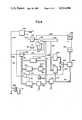
- FIG. 3is a schematic circuit diagram illustrating one preferred apparatus for carrying out the invention and employing a fixed interval of time between two different voltage measurements.
- FIG. 4is a schematic circuit diagram of another preferred apparatus for carrying out the invention in which a variable time interval is measured for the achievement of a predetermined voltage difference between two voltage measurements.
- FIG. 1there is shown two series of voltage curves plotted on an expanded vertical scale for nominal 36 volt battery systems. These curves are plotted on a logarithmic horizontal scale representing the time duration of the quiescent interval after termination of battery current.
- Curve 1represents the condition of 100% charge, and it is so marked.
- Curves 2, 3, 4, and 5respectively represent 80% charge, 60% charge, 40% charge, and 20% charge states.
- curves 6 through 9 and 11respectively represent 10%, 30%, 50%, 70%, and 90% charge states, and are respectively so marked.
- the curvesrepresent voltage stabilization characteristics to be expected from a particular 800 ampere hour lead acid traction battery having 18 cells at a temperature of 25° C.
- the curvesare typical of those to be expected from this battery type.
- the ultimate stabilized open circuit voltagemay be expressed as a function of battery charge to a very close approximation by the following expression:
- This expressioncalls for a fully discharged stabilized open circuit voltage of 35.46, and a fully charged stabilized open circuit voltage of 38.34 volts. These values are respectively shown, for reference purposes, in FIG. 1 at the right margin of the drawing at 13 and 15. Stabilized open circuit voltages for intermediate charge states are indicated at 10% intervals between the extreme values at 13 and 15. These stabilized open circuit voltage values are not related to the horizontal time scale since the stabilized voltage values are not actually achieved until a time substantially beyond the time scale shown, even though the time scale is a logarithmic scale.
- the curves of FIG. 1are idealized to some extent, but they generally represent the character of actual data on actual batteries. In the earliest portions of the quiescent intervals, up to about one tenth of a second, the recovery voltage characteristic has been found to be very much dependent upon the magnitude of the prior battery current. However, it has been discovered that after about one tenth of a minute, and especially after about one minute, all of the curves become quite mathematically predictable and regular, and appear to be substantially independent of the magnitude of the current prior to commencement of the quiescent interval, as long as there is a substantial energy transfer in a nominal period of time. Thus, the curves are almost straight lines, as plotted on the horizontal logarithmic scale, and thus represent essentially logarithmic functions, or at least predictable exponential functions. Because of this, the curves represent a basis for accurate prediction of the ultimate steady state open circuit terminal voltage, and that prediction provides a basis for accurately indicating the state of charge of the battery.
- FIG. 2is an idealized redrawing of FIG. 1 in which the quiescent interval time is plotted in hours, rather than in minutes, beginning with 1/10 of an hour (6 minutes) and continuing to 1000 hours, which is a very substantial extension of the time scale over FIG. 1. Additionally, in FIG. 2, the vertical scale is shown entirely in terms of the percent of stabilized battery capacity (as indicated by the stabilized terminal voltage) rather than by use of a battery terminal voltage scale.
- curves of FIG. 1are all again shown in FIG. 2, and are designated with the same numbers, but with a suffix letter A.
- curve 1 of FIG. 1is again shown in FIG. 2 as curve 1A.
- the curves of FIG. 2are idealized as straight lines on a semi-logarithmic plot. It has been found that such lines provide a rather accurate representation of the voltage recovery characteristics of the terminal voltage of the battery, particularly for the time intervals shown from about 6 minutes after the beginning of quiescence to 1000 hours. It has been found that the recovery curves from a last previously charged state, curves 1A, 2A, 3A, 4A, and 5A, do not have a common slope.
- the 100% charge curve 1Ahas a slope of about minus 12% per decade
- the 80% charge curve 2Ahas a slope of minus 10% per decade
- the 60% charge curve 3Ahas a slope of minus 8% per decade
- the 40% charge curve 4Ahas a slope of about minus 7% per decade
- the 20% charge curve 5Ahas a slope of about 6% per decade.
- a "decade”refers to the interval on the horizontal scale from one point to a subsequent point which represents 10 times the elapsed time. Thus, from 1 to 10 on the horizontal scale is one "decade".
- FIG. 2includes an additional curve 14A at the bottom of the figure which relates to a 0% charge condition.
- FIG. 3is a schematic circuit diagram illustrating a preferred embodiment of apparatus in accordance with the invention for carrying out the method according to the invention.
- the apparatuscan be very briefly described as follows:
- the battery for which the state of charge is to be determinedis schematically illustrated at 16.
- the battery 16is connected to a voltage controlled oscillator 18 which is connected to a counter 20.
- the counter 20is caused to count up for a predetermined fixed interval of time, as determined by a clock counter 22, to record a measurement of the battery voltage in digital form in terms of the count stored in the counter 20. Since the oscillator frequency is a function of voltage, the pulse count over a fixed interval is a function of voltage. The higher order digits of that count are then transferred to a register 24 for storage of the first voltage measurement for future use, and the counter 20 is then reversed to count down during a second voltage measurement interval the same fixed time duration.
- the remainder within the counter 20indicates the difference in voltage as measured by the two different measurements, such difference remaining in the lower order registers of counter 20. If the remainder in register 20 is positive, indicating a negative change in the voltage from battery 16, such positive remainder is analyzed by a digital logic network 26, and the result is used to modify the voltage value as stored in register 24, as will be described in more detail below, to provide a registration on a display meter 28 which indicates the state of charge of the battery 16. The negative change indicates a prior active condition of charging the battery.
- the apparatusis started by connecting the battery to the circuit by a connector schematically indicated at 32 which applies a logical 1 through connection 34 to a delay circuit 40, which may be a "single-shot” monostable multivibrator circuit.
- Delay circuit 40is immediately “set” to provide a logic 1 output at connection 38 for reset purposes as indicated by the symbol "R".
- the reset signalis applied to reset each of the counters 20, and 22, and the register 24.
- poweris supplied to all of the components of the circuit, permitting those components to stabilize in a condition ready for operation. While other power supplies may be provided in the apparatus, it is assumed that the apparatus will be powered by the battery being tested. Voltage dropping and voltage stabilizing circuits will normally be connected in line 34 for this purpose.
- NOR gate 44provides a logic 1 output at connection 46.
- the signal on connection 46is supplied to counter 20 as a "countup" enabling signal, causing the counter 20 to commence its upward count in response to pulses from the voltage controlled oscillator 18.
- a NOR gate 48which is similar to the NOR gate 44, is connected to receive the identical inputs supplied to NOR gate 44, except that an inverter 50 is provided between the output of stage 27 of timer counter 22 and the corresponding input of NOR gate 48. Therefore, at this time, NOR gate 48 is supplied with a logic "1" input from inverter 50 and continues to have a logic zero output on the output connection 52.
- the connection 52provides a count down enable signal to counter 20 when it later goes to a logic 1. Substantially concurrently with the commencement of the count up operation of counter 20, the timer counter 22, having also had the reset signal removed, commences a count up operation under the control of a timer oscillator 54, which provides timing signals through an OR gate 56.
- NOR gate 44by the logic 1 supplied through connection 58A to that NOR gate, to discontinue the count up of counter 20.
- the third functionis the enablement of NOR gate 48 by means of the logic 1 supplied to the input of inverter 50, which is then inverted to logic zero, to provide the logic 1 output from NOR gate 48 as the countdown enablement signal to counter 20 through connection 52.
- stage 27 of the timer counter 22After a countdown interval equal to the previous count up interval, the timer counter 22 counts up again until stage 27 of the timer counter 22 again goes to logic zero and stage 28 goes to logic 1.
- the logic 1 output from stage 28disables the NOR gate 48, and maintains the disablement of NOR gate 44 so that the counter 20 continues to hold and store the difference value achieved in the count up and subsequent countdown operations.
- a measurement completion signalis supplied from the output of stage 28 of counter 22 through a connection 64 to a second input to OR gate 56 to lock that OR gate so as to discontinue further transmissions of pulses to the timer counter 22.
- the completion signalis also supplied through a connection 64A to enable the output meter 28 to thereby provide a visual indication to the operator of the state of charge of the battery. That state of charge is computed by the remaining circuit components which are about to be described below.
- the resultant counting up and counting down of the voltage measurement counter 20occur in two adjacent time intervals. This provides two time-spaced voltage measurements. The difference between the voltage measurements in the two adjacent time intervals represents the equivalent of two different instantaneous voltage measurements spaced apart in time by the equivalent of the time from the middle of the first voltage measurement interval to the middle of the second voltage measurement interval. If desired, the voltage measurement intervals can be separated to provide a greater voltage change. This would require only a minor modification of the circuit as shown.
- the digital quantity stored in register 24is first converted from digital form to an analog voltage in a digital to analog converter 66.
- This voltagerepresents the full terminal voltage of the battery. Since the steady state terminal voltage of the battery does not go to zero when the battery is discharged, a zero offset must be introduced at some point in the system so that the meter 28 will read zero for a discharged battery and full scale for a fully charged battery (or vice versa).
- the zero correctionis preferably adjustable, since the determination of the terminal voltage which is to be regarded as indicating a fully discharged condition is partly a matter of judgment and preference.
- a typical stabilized votage per cell for a fully discharged batteryis 1.969 volts
- a typical stabilized voltage per cell for a fully charged battery cellis 2.131 volts.
- a fixed factor Ncorresponding to the stabilized "empty" voltage per cell, is subtracted from the output signal from converter 66 at 68 in a subtract circuit 70.
- the analog signal voltage at 68, and the factor N signalare preferably scaled down from the typical actual terminal voltage to provide for a full scale reading on meter 28 (after further correction) for a fully charged battery, and a zero reading for a fully discharged battery.
- the scales and voltagesmay be selected, for instance, to provide one volt at meter 28 to indicate 100% charge.
- the subtract circuit 70may be simply carried out by means of an amplifier with the inputs combined in a resistor network so that the voltage output is offset by the amount of the subtracted offset signal N.
- the offset corrected signalis supplied on a connection 72 to an analog add circuit 74, where a correction is added through a connection 82 based upon the detected change in the voltage to the second voltage measurement.
- the corrected signalis then supplied from the adder 74 through connection 76 to the meter 28.
- Add circuit 74may also consist of an amplifier with a resistance network to combine the two input signals at a common amplifier input.
- the correction to be applied at the adder 74is determined by the logic network 30.
- This rising terminal voltage conditionindicates a last previous non-quiescent status of the battery in the discharge mode. This refers back to the curves 6A through 11A, and 14A, of FIG. 2.
- the negative remainder condition in counter 20is characterized by having the counter go into the complement mode, in which, after having counted down to zero, all of the stages of the counter are shifted to the "one" state, and then counted down in the complement mode.
- This complemented conditionis recognized and used by detecting a 1 output from the 20th stage of counter 20 on a connection 78 to a visual indicator 85 and to an electronic switch 80.
- the signal to the visual indicator 85provides the information that the battery was last in the discharge mode.
- Another visual indicatoralso could be provided to indicate the opposite situation where the battery was last in the charge mode.
- Switch 80determines whether the correction signal to adder 74 on input connection 82 is to be supplied from network 30 and a function generator 87 on connection 84, or from network 26 and a function generator 89 on connection 86.
- the switch 80When a logic 1 signal is available at connection 78, the switch 80 is in the position shown to provide the correction signal on connection 84 from network 30 and a function generator 87 to connection 82 to the adder 74.
- the switch 80is switched to the other position to receive the correction signal through connection 86 from logic network 26 and a function generator 89.
- Switch 80is a schematically illustrated electronic switch.
- the logic network 30is designed to provide a stepwise indication of the value of the remainder in counter 20. It has been discovered that stepwise corrections, with a reasonable number of steps, provide sufficient accuracy in the correction factor applied to the voltage to be indicated at indicator 28. Since the counter 20 is a binary digital counter, the highest value step in the negative residue value, as indicated by logic zeros in the 10th or 11th stage of the counter is in the range from a count of 512 to 2047. Thus, starting at the count 512, the 10th stage first goes to zero, and starting at the count 2048, the 12th stage first goes to zero, and the 10th and 11th stages both go to ones.
- the condition of the highest count range, in which either of the 10th or 11th stages provides a logic zero output,is detected by a NAND gate 88, which provides a logic one in that condition.
- the range step from 128 to 511is detected by the NAND gate 90, and other lower order steps are detected by NAND gates 92, 94, and 96.
- the stepsare respectively in the value ranges from 32 to 127, from 8 to 31, and from 2 to 7. However, in each lower range, other logic is necessary to make sure that the range has not been surpassed.
- the range from 128 to 511as determined by stages 8 and 9, there must be an assurance that the count has not already exceeded 511 by checking for logic zeros in stages 10 and 11.
- the signal from NAND gate 88is supplied through an inverter 98 to an AND gate 100, which also receives the output from gate 90, so that, unless there is a logic zero output from NAND gate 88, indicating that the value has not yet exceeded 511, there can be no signal provided from NAND gate 90 through AND gate 100 for an indication of that step value.
- additional AND gates 102, 104, and 106are provided for each of the other lower order ranges which are controlled by NOR gates 108, 110, and 112 to indicate that no higher order stages of the counter 20 have flipped over to zero.
- the correction function generator 87receives any one of the five stepwise signals from the logic network 30, and converts each of those signals to an appropriate correction factor for addition at adder 74.
- a sixth correction factoris available from the correction function generator 87 if none of the five inputs is available. This is the condition which exists when the remainder stored in counter 20 is a count of minus 1, or is in the positive instead of the negative range. However, this correction factor is only effective at the count of minus 1, because the counter 20 is not in the complement state when the remainder is positive. As explained previously, the counter 20 must be in the complement state in order to enable the switch 80 to obtain a correction from the correction function generator 87. At any rate, when the remainder in counter 20 is negative (in the complement mode) and at the smallest measurable count of minus 1, this sixth value from the correction function generator 87 is available at the output of that generator on connection 84.
- curve 7Afor the recovery from a discharge condition in a 30% charge state.
- the beginning of that curve, at 0.1 hours after quiescence beginsis at a value of 14 on the zero corrected percent of charge scale.
- the zero corrected output from subtractor 70would be 0.14 volts.
- the rate of change detected at 0.1 hourswould be in the range of counts in Table 1 at the step of -128 to -511. Therefore, the correction voltage provided by the correction function generator 87 would be 0.17, which when added to the previous value of 0.14 in the adder 74 provides 0.31 volts, which provides a close approximation to a 30% charge reading on meter 28.
- stepwise voltage measurement residue countsessentially represent approximate antilogarithmic functions of the residue counts. While a greater number of steps could be taken to provide greater precision, or a continuous computation could be made, it has been discovered that these stepwise approximations are adequate for providing a measurement within the limits of accuracy within the apparatus.
- the relationships stated in the above Table, together with the zero corrected voltage measurement available from subtractor 70,represent a means for matching the data plotted in FIG. 2 for the recovery curves from a prior discharge condition within this apparatus for computing the state of charge.
- the correction factors shown in the above Table 1 for the different stepshave been selected to match with the slopes of the curves for a particular battery. A different table of correction factors can be selected for a different battery.
- the correction function generator 87can be carried out in various ways which are known to the art.
- the five logic network 30 outputsmay control five electronic switches which connect different voltages from different parts of a voltage divider network to the output connection 84 to be added into the adder 74.
- the voltage controlled oscillator 18may be selected to produce 34,293.55 counts per minute per volt. If greater resolution is desired on the low end of the scale, an oscillator which operates at a higher frequency per volt may be employed, with appropriate adjustments of the correction functions supplied from the correction function generator 87. Greater resolution can also be achieved by designing the circuit to provide for an accumulation of the counts over longer timing intervals than one minute, or by time separation of the two timing intervals.
- Logic network 26operates on principles similar to network 30 to respond to a positive residual in counter 20.
- the positive residualindicates that the battery was last in a prior charge condition, and an appropriate voltage correction signal is needed.
- the situationis complicated by the fact that the slopes of the recovery curves from the prior charge condition are not perfectly uniform. Thus, the slopes are greater for higher conditions of charge, and lower for lower conditions of charge.
- network 26includes a series of five OR gates 114-122.
- OR gate 122detects the condition where the residual count is in the range from 512 to 2047, and provides that signal as one of the input signals to function generator 89 which may be a variable gain amplifier. Thus, if the count is high enough so that either the 10th or 11th stages contain a binary 1, the OR gate 122 provides an output to the variable gain amplifier 89.
- each of the OR gates 114-120indicates the presence of a binary 1 in either one of a connected pair of stages of the counter.
- AND gates 126-132are respectively provided to exclude the condition that higher order binary 1 digits exist.
- NOR gates 134-138, and an inverter 140are provided.
- AND gate 128For a true indication for the second step by means of an output from AND gate 128, not only must there be a binary 1 in the 4th or 5th stage to provide a binary 1 output from OR gate 116, but there must not be a binary 1 output from any of the higher order OR gates 118, 120, and 122, as detected by the NOR gate 136, so that NOR gate 136 will continue to provide a logic 1 to AND gate 128.
- the corrections provided from the variable gain amplifier 89are determined partly by the level of the voltage measured and stored in register 24. This is accomplished by providing the zero corrected output signal on connection 72 to the variable gain amplifier 89 through an adder 142. In the adder 142, a fixed signal M is added. It has been found that an appropriate constant M to be added corresponds to 50% of the full scale full charge signal. This is the signal indicated at the second input to adder 142.
- Adder 142may be implemented by an amplifier with a resistor summing network for summing the two inputs.
- variable gain amplifier 89The output from adder 142 at connection 144 to the variable gain amplifier 89 is then amplified in the amplifier 89 by a selected one of five different amplification factors, determined by the step detected by the logic network 26. The resultant signal is then supplied through connection 86 to switch 80 and thus through connection 82 to the adder 74 for correction of the voltage to be supplied to the meter 28.
- the variable gain amplifier 89is operable, in the absence of any one of the five inputs from network 26, to provide a predetermined small variable gain in recognition that the remainder value stored in register 20 is either zero or 1, and therefore the slope is so low that it is considered to be indeterminate.
- a sixth inputcan be provided to the variable gain amplifier 89 from the first stage of the counter 20, and that stage can be used to provide another gain factor different from any factor provided with a zero count.
- the multiplication factors (amplification factors) provided by the variable gain amplifier (multiplier) 89 for the various different residue countsare preferably as shown in the following table:
- the multiplication factor from Table 2will be -0.242, providing an output on connection 86 of -0.479 which is added (actually subtracted because it is a negative number) to the 1.48 volts in the adder 74 to provide a resultant voltage of just a trifle over 1 volt to the meter 28 as a correct indication of the full charge condition.
- the computationsare carried out by means of analog devices in FIG. 3. It will be quite apparent that digital logic could be easily employed, since the raw data from the counter 20 is in digital form, and since the logic networks 26 and 30 comprise digital elements.
- the correction function generator 87can be simply a "look up" table of values which are selected by the five inputs from the logic network 30.
- the variable gain amplifier 89in digital form, may simply comprise a multiplier with a "look up” table to select different multiplication factors. It will be apparent that the characteristics of the circuit could be easily changed by changing the "look up" tables in the correction function generator 87 and the variable gain amplifier 89.
- the adders 74 and 142, and the subtractor 70,are replaced by digital devices, and the digital-to-analog converter 66 is omitted. It will also be understood that, particularly in a digital version, an appropriately programmed microprocessor, with associated working memory, can be employed to carry out the functions of the system, with a minimum of special dedicated components.
- the voltage recovery curves illustrated in FIG. 1 and FIG. 2assume a substantial prior energy transfer between the battery and another device. For instance, those curves assume a normally heavy load applied for an interval of at least several minutes, or a normally heavy charge current applied for at least five minutes or so. Thus, a very brief interval of regenerative braking, or a very brief application of a normal load, or the application of a very light load for a longer interval, will not result in the substantial deviations of terminal voltage from the ultimate steady state voltages illustrated in FIGS. 1 and 2. Consequently, the voltage recovery curves after such minor current exchange incidents will not be as steep. Therefore, the battery will appear to be closer to its steady state condition at the outset of the quiescent condition.
- the inventionalso tends to automatically compensate for variations in the temperature of the battery for battery systems in which changes in voltage fluctuations caused by changes in temperature are accompanied by similar changes in the voltage recovery characteristics. For instance, in such a system, under load, the terminal voltage will decrease more when the battery is cold. However, the voltage recovery curve will also present a steeper slope, and the battery will look to the system as though it is simply at an earlier stage in the recovery towards a steady state condition compared to operation at normal temperature.
- the embodiment of FIG. 3may incorporate a temperature sensing device to sense the temperature of the battery 16 and to modify the operation of the circuits in accordance with that sensed temperature. If the temperature is higher than normal, the battery becomes more electrochemically active, and if the temperature is lower than normal, the battery becomes less electrochemically active, modifying the voltage characteristics depicted in FIG. 2.
- a temperature signal derived from a temperature sensor at the battery 16may preferably be applied, as indicated at 146 and 148 to the correction function generator 87 and to the variable gain amplifier 89, and as indicated at 150 to the subtract circuit 70.
- the temperature correction input to the subtract circuit 70 at 150will change and adjust, on a continuous, or in a stepwise manner, the offset correction of the voltage value derived from the number stored in register 24.
- the temperature correction at 146 to the correction function generator 87will modify the correction functions selected by each of the five inputs to the correction function generator 87 from network 30. This modification may likewise be on a continuous, or in a stepwise manner.
- the detection of a temperature above or below certain limitsmay simply switch in a new "look up" table of values to be selected by the five inputs.
- the temperature correction input at connection 148may select different variable gain values for the amplifier 89.
- FIG. 3illustrates an embodiment of the invention in which two voltage measurements are made at a fixed time separation, and the voltage difference over the fixed time is used to derive a correction to the total voltage amplitude measurement.
- another very useful procedureis to look for a voltage change of a predetermined fixed amplitude, while measuring the variable time to achieve that voltage change, and then using that time measurement to derive the appropriate correction.
- FIG. 4is a schematic circuit diagram of another embodiment of the invention in which the time between a first voltage measurement and a second voltage measurement is variable, and is measured, until a predetermined voltage difference is achiieved. The elapsed time is then used as a quantity for calculation of the appropriate correction for prediction of the steady state open circuit voltage and the determination of the state of charge.
- connection device 32Bwhich may be of conventional construction. This results in the application of battery terminal voltage at connection 34B to an analog-to-digital converter 20B, and also to a delay circuit 40B, which may be a monostable multi-vibrator, sometimes referred to as a "single-shot" circuit.
- Delay circuit 40Bis immediately “set,” providing an output on connection 38B to reset all of the components of the circuit, the individual reset circuits not being illustrated.
- the setting of the delay circuit 40Binitiates the timing of a delay interval, at the end of which the delay circuit resets, thus terminating the reset signal at 38B.
- Reset of delay circuit 40Balso makes available a delayed signal on connection 42B which is supplied as an input to a gate 152, which is normally enabled by a NAND gate 154 to provide an output at connection 64B.
- the output at 64Bdisables the display device 28B, and enables an AND gate 56B.
- the enablement of AND gate 56Bgates clock signals from a clock oscillator 54B into a counter 22B which serves as an elapsed time indicator, and also as a clock commutator control for the operation of the system.
- the analog-to-digital converter 20Bmay be carried out in various ways. In one embodiment, it may include the voltage responsive variable frequency oscillator 18 of FIG. 3, the counter 20 of FIG. 3, and a timer such as counter 22 of FIG. 3 or it may employ timing connections (not shown) to the existing counter 22B of FIG. 4. At any rate, the analog-to-digital converter 20B is capable of taking the voltage signal available from battery 16 and converting that voltage signal to a digital quantity from time to time when enabled by a control signal pulse on connection 156 from the commutator control 22B. That digital quantity is then available on a data bus 158 to a storage register 24B and to two comparator circuits 160 and 162.
- the commutator control 22Bissues an enablement control pulse on a connection 62B to the register 24B, causing that register to read the number available upon the data bus 158 from the analog-to-digital converter 20B. That quantity, corresponding to the first voltage measurement, then remains stored in register 24B for the remainder of the operation of the apparatus for obtaining a particular reading at meter 28B. No more enabling pulses are emitted on connection 62B to register 24B during that operation of the apparatus. Accordingly, the quantity stored in 24B remains the same, and that quantity appears and continues to be available on an output bus 164.
- the quantity appearing on the output bus 164is incremented by a fixed factor P in an adder 166, and is compared in comparator 160 with new voltage readings from the analog-to-digital converter 20B appearing on bus 158.
- the first voltage reading quantity appearing on bus 164is decremented by a fixed factor L in an adder 168, and is compared in comparator circuit 162 with the new voltage readings from the analog-to-digital converter 20B.
- the comparator 160is operable to provide an output at an output connection 170 as soon as the condition is detected in which the latest number appearing on bus 158 from the analog-to-digital converter (representing the latest voltage reading) exceeds the incremented number from adder 166.
- comparator 162is operable to provide an output signal on connection 172 when it first detects that the number on bus 158 is less than the number on bus 164 as decremented by factor L in adder 168. This is the condition which indicates a match with a second point on one of the decreasing voltage characteristic curves 1A-5A.
- the factors P and Leach represent a fixed voltage difference between a first reading and a second reading which is to be detected by the compare circuits 160 and 162.
- P and Lmay be equal in magnitude, but not necessarily.
- the negative slope curves 1A through 5Ahave a greater slope than do the positive slope curves 6A et seq. Therefore, the factor L, which is used to recognize negative slopes, may be selected to be somewhat smaller than the factor P which is used to recognize positive slopes, since a significant measureable value will be available in a shorter time with the negative slopes.
- Lmay be selected to be larger than P, so that the times to achieve the fixed change in voltage may be comparable for the negative slope curves and the positive slope curves.
- NAND gate 154is also provided with a clock signal on connection 178 after each operation of the analog-to-digital converter 20B. Accordingly, as soon as an operation of the analog-to-digital converter 20B results in an output from one of the comparators 160 or 162, the next succeeding commutation signal to NAND gate 154 on connection 178 results in a logic zero output from NAND gate 154. This disables gate 152, resulting in the disablement of AND gate 56B so as to stop counter 22B. The disablement of gate 152 also removes the disablement signal on connection 64B to the meter 28B, so that the apparatus may indicate the state of charge.
- the state of chargeis derived from the circuitry now to be described.
- the initial voltage measurement number appearing on bus 164is supplied to an adder 70A.
- adder 70Aa factor N is subtracted from the number to provide the "zero" correction so that the meter 28B may read on an expanded scale basis to show zero for fully discharged and full scale for fully charged.
- the quantity from adder 70Ais then transmitted to an adder 74B which provides a correction function based on the voltage difference measurement. That function is added through data switch 80A. After the addition of that correction function, the data is transferred to a data converter 180 to convert the data to a form which is usable by the meter 28B.
- the data converter 180may be a digital-to-analog converter if the meter is an analog meter, as shown, or the converter 180 may be a digital converter for converting the data to a digital form for use by an indicator.
- a formmay be a seven segment code for energizing a decimal digit readout device, or a one out of N code converter for providing a digital display which simulates a moving pointer.
- the correction factors provided through switch 80Aare from correction transform circuits 87A and 89A, and are based upon elapsed time measurements available from the elapsed time counter 22B on a bus 182. Recognition of whether the curve matching by the operation of the comparators 160 and 162 was accomplished for a positive voltage difference by comparator 160, or for a negative voltage difference by comparator 162, is accomplished by means of an extension 170C of the output line 170 from the positive comparator 160 to switch 80A. The resultant enablement of the switch 80A causes the switch to connect the positive correction transform device 87A through to the adder 74B. Otherwise, the switch 80A is normally in the position to connect the negative transform circuit 89A to the adder 74B. It will be appreciated that switch 80A is only schematically shown, as it will typically be an electronic digital switch which may include a number of logic gates.
- the correction transform circuits 87A and 89each generate signals which are representative of an inverse anti-logarithmic function of the elapsed time from the first measurement to the second measurement.
- the elapsed time signalis supplied on connection 182 to each of these transform circuits.
- the function generated by each transform circuitis an inverse function because a greater elapsed time required for the predetermined voltage difference to develop indicates that the battery has been in a quiescent state for a longer interval, and it's closer to the steady state open circuit condition so that a smaller correction is required to provide the correct output.
- the lowest order stages of the counter 22Bmay be used for the clock commutator control of the operations of the converter 20B by the timing pulse on connection 156, and for testing to see if a comparison output is available by means of the timing pulse on connection 178 to the NAND gate 154.
- a new comparisonmay be made and checked.
- timeis essentially a logarithmic function in the curves which are to be matched, as the elapsed time becomes longer, it is not necessary to have equally time spaced tests for comparison.
- an alternative arrangement for the circuit of FIG. 4is to provide for a logarithmic time function advance of the counter 22B. This can be accomplished in various ways by providing for progressively increasing time spacing between successive pulses from the clock 54B.
- One very useful methodis to provide a pulse divider circuit between the clock oscillator 54B and the AND gate 56B in which the division factor is variable and controlled by the accumulated count in the counter 22B.
- temperaturemay be measured, and temperature compensation signals incorporated, as discussed above in connection with FIG. 3.
- temperature compensation input signalsare not indicated in FIG. 4.
- FIG. 3in which the voltage difference is measured over a fixed interval of time, provides the best results when used in the earlier portions of the quiescent battery interval when the voltage changes per unit of time are high.
- FIG. 4in which the time is measured for a predetermined fixed change in voltage, provides better resolution when the test is made later in the quiescent interval when the changes in terminal voltage are less rapid. If the FIG. 3 embodiment is used in the low slope regions of the quiescent interval, the difference in voltage over the fixed interval of time may be so small that it is very difficult to measure. On the other hand, the system of FIG. 4 provides less resolution in the steep slope operating regions.
- the systems of FIG. 3 and FIG. 4may be combined, the operation of both systems being started simultaneously. If, at the end of the fixed time interval, the difference voltage detected by the remainder in counter 20 of the FIG. 3 system is very small, or not measurable, then the system of FIG. 4 is operable to measure for a fixed voltage difference over a variable time interval.
- a combined systemmakes use of the advantages of both of the systems of FIGS. 3 and 4.
- each of the individual systems of FIGS. 3 and 4preferably operate independently of one another, and preferably share a common output meter, with simple logic gates which permit only the first of the two systems which comes up with a meaningful output to take possession of the output meter and place its output on that meter.
- the system of FIG. 3would lock itself out so that only the system of FIG. 4 would ultimately register an output on the meter.
- two sets of FIG. 3 apparatusmay be employed, having two different fixed time intervals. If, at the end of the shorter fixed time interval, the difference voltage detected by the remainder in counter 20 is very small, or not measurable, then the second FIG. 3 apparatus, providing a longer time interval, is switched in and becomes operative. In this same manner, more than two fixed time intervals may be employed until a reading of sufficient significance is obtained.
- the description of the inventionis given entirely in terms of measuring a single voltage difference between one pair of points in time. It will be apparent, however, that the method and apparatus of the invention can be easily expanded to provide for a series of measurements of voltage differences, and for crosschecking from one voltage difference measurement to another to verify the correctness of the measurements in order to enhance the accuracy.
- FIGS. 3 and 4are schematic representations. It will be understood that additional components such as logic gates may be desirable in order to refine the operations of these circuits and to prevent problems such as undesired back circuits. Also, power supplies, voltage scaling circuits, and other refinements are not shown.
- the quiescent voltage recovery characteristics given in FIGS. 1 and 2are typical characteristics for some lead acid system batteries.
- other batteriesmay display other quiescent voltage recovery characteristics, and adjustments in the functions provided by the function generators 87 and 89 of FIG. 3 may be made to accommodate to those other characteristics.
- a function generator similar to the function generator 87may be used for the function generator 89, without the multiplication function.
- the correction function generator 87may be replaced by a function generator similar to function generator 89, incorporating a multiplication function.
- the correction function generator 89operates by multiplication of a factor corresponding to the voltage obtained from register 24 through digital-to-analog converter 66 after modification in the subtractor 70 and the adder 142.
- the subtractor 70subtracts one factor, and the adder 142 adds another factor. Therefore, the signal at the output from adder 142 at connection 144 represents the voltage level signal, with what may be characterized as a "zero level adjustment,” to provide a zero level adjusted value of the voltage level.
- a desirable added feature for the system of FIG. 4is a time-out switching feature which causes the meter to register the zero corrected first voltage measurement supplied through the subtractor 70A, without the addition of a correction factor in adder 74B, after a considerable interval has elapsed without the achievement of the fixed voltage difference. This assumes that the slope of the recovery curve is so low that the difference between the first voltage measurement and steady state battery terminal voltage is inconsequential.
Landscapes
- Engineering & Computer Science (AREA)
- Life Sciences & Earth Sciences (AREA)
- Sustainable Development (AREA)
- Sustainable Energy (AREA)
- Power Engineering (AREA)
- Transportation (AREA)
- Mechanical Engineering (AREA)
- Physics & Mathematics (AREA)
- General Physics & Mathematics (AREA)
- Charge And Discharge Circuits For Batteries Or The Like (AREA)
- Tests Of Electric Status Of Batteries (AREA)
Abstract
Description
TABLE 1 ______________________________________ Range of Residue Count Add Following Percent ______________________________________ -1 4 -2 to -7 8 -8 to -31 11 -32 to -127 14 -128 to -511 17 -512 to -2047 20 ______________________________________
TABLE 2 ______________________________________ RANGE OF MULTIPLICATION RESIDUE COUNT (AMPLIFICATION) FACTOR ______________________________________ 0 to 1 -0.07 2 to 7 -0.137 8 to 31 -0.165 32 to 127 -0.194 128 to 511 -0.218 512 to 2047 -0.242 ______________________________________
Claims (32)
Priority Applications (1)
| Application Number | Priority Date | Filing Date | Title |
|---|---|---|---|
| US06/401,383US4514694A (en) | 1981-07-23 | 1982-07-23 | Quiescent battery testing method and apparatus |
Applications Claiming Priority (2)
| Application Number | Priority Date | Filing Date | Title |
|---|---|---|---|
| US06/286,271US4460870A (en) | 1981-07-23 | 1981-07-23 | Quiescent voltage sampling battery state of charge meter |
| US06/401,383US4514694A (en) | 1981-07-23 | 1982-07-23 | Quiescent battery testing method and apparatus |
Related Parent Applications (1)
| Application Number | Title | Priority Date | Filing Date |
|---|---|---|---|
| US06/286,271Continuation-In-PartUS4460870A (en) | 1981-07-23 | 1981-07-23 | Quiescent voltage sampling battery state of charge meter |
Publications (1)
| Publication Number | Publication Date |
|---|---|
| US4514694Atrue US4514694A (en) | 1985-04-30 |
Family
ID=26963698
Family Applications (1)
| Application Number | Title | Priority Date | Filing Date |
|---|---|---|---|
| US06/401,383Expired - LifetimeUS4514694A (en) | 1981-07-23 | 1982-07-23 | Quiescent battery testing method and apparatus |
Country Status (1)
| Country | Link |
|---|---|
| US (1) | US4514694A (en) |
Cited By (172)
| Publication number | Priority date | Publication date | Assignee | Title |
|---|---|---|---|---|
| US4888716A (en)* | 1986-04-14 | 1989-12-19 | Hitachi, Ltd. | Life diagnosis apparatus for automotive battery |
| US5284719A (en)* | 1992-07-08 | 1994-02-08 | Benchmarq Microelectronics, Inc. | Method and apparatus for monitoring battery capacity |
| US5357203A (en)* | 1992-07-08 | 1994-10-18 | Benchmarq Microelectronics, Inc. | Battery monitoring circuit for operating with high battery discharge rates |
| US5432429A (en)* | 1990-10-23 | 1995-07-11 | Benchmarq Microelectronics, Inc. | System for charging/monitoring batteries for a microprocessor based system |
| US5440221A (en)* | 1992-07-08 | 1995-08-08 | Benchmarg Microelectronics, Inc. | Method and apparatus for monitoring batttery capacity with charge control |
| US5444759A (en)* | 1993-09-20 | 1995-08-22 | Northern Telecom Limited | Method of predicting voltages in telephone line measurement |
| US5552953A (en)* | 1994-01-29 | 1996-09-03 | International Business Machines Corporation | System for supplying power to an apparatus and method for the assessment of the lifetime and capacity of a power-storage device |
| US5565760A (en)* | 1994-11-02 | 1996-10-15 | General Electric Company | Electrical propulsion systems for a golf car |
| US5606592A (en)* | 1993-06-16 | 1997-02-25 | Industrial Technology, Inc. | Method and apparatus for analyzing resistive faults on telephones cables |
| US5698965A (en)* | 1995-12-01 | 1997-12-16 | Flight Systems, Inc. | Apparatus and method for determining the current state of charge of a battery by monitoring battery voltage increases above and decreases below a threshold |
| WO1998004910A1 (en)* | 1996-07-29 | 1998-02-05 | Midtronics, Inc. | Method and apparatus for auditing a battery test |
| USRE36454E (en)* | 1994-11-02 | 1999-12-21 | General Electric Company | Electrical propulsion systems for a vehicle |
| US6081098A (en)* | 1997-11-03 | 2000-06-27 | Midtronics, Inc. | Method and apparatus for charging a battery |
| US6137269A (en)* | 1999-09-01 | 2000-10-24 | Champlin; Keith S. | Method and apparatus for electronically evaluating the internal temperature of an electrochemical cell or battery |
| US6163156A (en)* | 1999-11-01 | 2000-12-19 | Midtronics, Inc. | Electrical connection for electronic battery tester |
| US6172483B1 (en) | 1998-09-11 | 2001-01-09 | Keith S. Champlin | Method and apparatus for measuring complex impedance of cells and batteries |
| US6172505B1 (en) | 1998-04-27 | 2001-01-09 | Midtronics, Inc. | Electronic battery tester |
| US6222369B1 (en) | 1998-09-11 | 2001-04-24 | Keith S. Champlin | Method and apparatus for determining battery properties from complex impedance/admittance |
| US6225808B1 (en) | 2000-02-25 | 2001-05-01 | Midtronics, Inc. | Test counter for electronic battery tester |
| US6249124B1 (en) | 1999-11-01 | 2001-06-19 | Midtronics, Inc. | Electronic battery tester with internal battery |
| US6262563B1 (en) | 1998-09-11 | 2001-07-17 | Keith S. Champlin | Method and apparatus for measuring complex admittance of cells and batteries |
| US6294896B1 (en) | 1998-09-11 | 2001-09-25 | Keith S. Champlin | Method and apparatus for measuring complex self-immitance of a general electrical element |
| US6304087B1 (en) | 2000-09-05 | 2001-10-16 | Midtronics, Inc. | Apparatus for calibrating electronic battery tester |
| US6310481B2 (en) | 1997-01-13 | 2001-10-30 | Midtronics, Inc. | Electronic battery tester |
| US6313607B1 (en) | 1999-09-01 | 2001-11-06 | Keith S. Champlin | Method and apparatus for evaluating stored charge in an electrochemical cell or battery |
| US6316914B1 (en) | 1999-05-05 | 2001-11-13 | Midtronics, Inc. | Testing parallel strings of storage batteries |
| US6323650B1 (en) | 1999-04-08 | 2001-11-27 | Midtronics, Inc. | Electronic battery tester |
| US6329793B1 (en) | 1996-07-29 | 2001-12-11 | Midtronics, Inc. | Method and apparatus for charging a battery |
| US6332113B1 (en) | 1996-10-07 | 2001-12-18 | Midtronics, Inc. | Electronic battery tester |
| US6331762B1 (en) | 1997-11-03 | 2001-12-18 | Midtronics, Inc. | Energy management system for automotive vehicle |
| US6351102B1 (en) | 1999-04-16 | 2002-02-26 | Midtronics, Inc. | Automotive battery charging system tester |
| US6359441B1 (en) | 1999-04-30 | 2002-03-19 | Midtronics, Inc. | Electronic battery tester |
| US6363303B1 (en)* | 1999-11-01 | 2002-03-26 | Midtronics, Inc. | Alternator diagnostic system |
| US6377028B1 (en) | 1990-10-23 | 2002-04-23 | Texas Instruments Incorporated | System for charging monitoring batteries for a microprocessor based method |
| US6417669B1 (en) | 2001-06-11 | 2002-07-09 | Keith S. Champlin | Suppressing interference in AC measurements of cells, batteries and other electrical elements |
| US6424158B2 (en) | 1998-07-27 | 2002-07-23 | Midtronics, Inc. | Apparatus and method for carrying out diagnostic tests on batteries and for rapidly charging batteries |
| US6441585B1 (en) | 1999-06-16 | 2002-08-27 | Midtronics, Inc. | Apparatus and method for testing rechargeable energy storage batteries |
| US6445158B1 (en) | 1996-07-29 | 2002-09-03 | Midtronics, Inc. | Vehicle electrical system tester with encoded output |
| US6456045B1 (en) | 1999-04-16 | 2002-09-24 | Midtronics, Inc. | Integrated conductance and load test based electronic battery tester |
| US6466025B1 (en) | 2000-01-13 | 2002-10-15 | Midtronics, Inc. | Alternator tester |
| US6466026B1 (en) | 2001-10-12 | 2002-10-15 | Keith S. Champlin | Programmable current exciter for measuring AC immittance of cells and batteries |
| US6469511B1 (en) | 2001-07-18 | 2002-10-22 | Midtronics, Inc. | Battery clamp with embedded environment sensor |
| US20020171428A1 (en)* | 1997-11-03 | 2002-11-21 | Bertness Kevin I. | Electronic battery tester with network communication |
| US20020180445A1 (en)* | 2000-09-14 | 2002-12-05 | Bertness Kevin I. | Method and apparatus for testing cells and batteries embedded in series/parallel systems |
| US20030001579A1 (en)* | 1996-07-29 | 2003-01-02 | Bertness Kevin I. | Method and apparatus for auditing a battery test |
| US20030038637A1 (en)* | 1997-11-03 | 2003-02-27 | Bertness Kevin I. | Automotive vehicle electrical system diagnostic device |
| US20030056124A1 (en)* | 2001-09-19 | 2003-03-20 | Amick Brian W. | Digital-based mechanism for determining voltage |
| US6544078B2 (en) | 2001-07-18 | 2003-04-08 | Midtronics, Inc. | Battery clamp with integrated current sensor |
| US20030088375A1 (en)* | 2001-10-17 | 2003-05-08 | Bertness Kevin I. | Electronic battery tester with relative test output |
| US6566883B1 (en) | 1999-11-01 | 2003-05-20 | Midtronics, Inc. | Electronic battery tester |
| US6586941B2 (en) | 2000-03-27 | 2003-07-01 | Midtronics, Inc. | Battery tester with databus |
| US20030124417A1 (en)* | 1999-04-08 | 2003-07-03 | Bertness Kevin I. | Battery test module |
| US20030173971A1 (en)* | 2002-03-14 | 2003-09-18 | Bertness Kevin I. | Electronic battery tester with battery failure temperature determination |
| US20030184258A1 (en)* | 2001-06-22 | 2003-10-02 | Vonderhaar J. David | Booster pack with storage capacitor |
| US20030184306A1 (en)* | 2002-03-29 | 2003-10-02 | Bertness Kevin I. | Battery tester with battery replacement output |
| US6633165B2 (en) | 1997-11-03 | 2003-10-14 | Midtronics, Inc. | In-vehicle battery monitor |
| US20030222867A1 (en)* | 2002-06-04 | 2003-12-04 | Bean Heather N. | Energy consumption-rate indication for a battery-powered electronic device |
| US6696819B2 (en) | 2002-01-08 | 2004-02-24 | Midtronics, Inc. | Battery charge control device |
| US20040036443A1 (en)* | 2000-03-27 | 2004-02-26 | Bertness Kevin I. | Modular battery tester for scan tool |
| US20040046564A1 (en)* | 2002-09-05 | 2004-03-11 | Klang James K. | Battery test outputs adjusted based upon battery temperature and the state of discharge of the battery |
| US20040046566A1 (en)* | 2002-09-05 | 2004-03-11 | Klang James K. | Electronic battery tester configured to predict a load test result |
| US6737831B2 (en) | 1999-09-01 | 2004-05-18 | Keith S. Champlin | Method and apparatus using a circuit model to evaluate cell/battery parameters |
| US20040104728A1 (en)* | 1996-07-29 | 2004-06-03 | Bertness Kevin I. | Alternator tester with encoded output |
| US6759849B2 (en) | 2000-03-27 | 2004-07-06 | Kevin I. Bertness | Battery tester configured to receive a removable digital module |
| US20040140904A1 (en)* | 2003-01-22 | 2004-07-22 | Bertness Kevin I. | Apparatus and method for protecting a battery from overdischarge |
| US20040145371A1 (en)* | 2001-10-17 | 2004-07-29 | Bertness Kevin I | Query based electronic battery tester |
| US20040157113A1 (en)* | 2002-12-31 | 2004-08-12 | Midtronics, Inc. | Apparatus and method for predicting the remaining discharge time of a battery |
| US6781382B2 (en) | 2002-12-05 | 2004-08-24 | Midtronics, Inc. | Electronic battery tester |
| US6788025B2 (en) | 2001-06-22 | 2004-09-07 | Midtronics, Inc. | Battery charger with booster pack |
| US6795782B2 (en) | 1999-04-08 | 2004-09-21 | Midtronics, Inc. | Battery test module |
| US20040189308A1 (en)* | 2003-03-25 | 2004-09-30 | Bertness Kevin I. | Electronic battery tester |
| US20040232918A1 (en)* | 1996-07-29 | 2004-11-25 | Bertness Kevin I. | Automotive battery charging system tester |
| US20040251876A1 (en)* | 2001-06-22 | 2004-12-16 | Midtronics, Inc. | Apparatus and method for counteracting self discharge in a storage battery |
| US20040251908A1 (en)* | 2003-06-16 | 2004-12-16 | Midtronics, Inc. | Electronic battery tester having a user interface to configure a printer |
| US20040257084A1 (en)* | 2003-06-23 | 2004-12-23 | Restaino Harvey A. | Cable for electronic battery tester |
| US20050021475A1 (en)* | 1996-07-29 | 2005-01-27 | Bertness Kevin I. | Electronic battery tester with relative test output |
| US6850037B2 (en) | 1997-11-03 | 2005-02-01 | Midtronics, Inc. | In-vehicle battery monitor |
| US20050035752A1 (en)* | 1996-07-29 | 2005-02-17 | Bertness Kevin I. | Alternator tester |
| US20050052187A1 (en)* | 2003-09-05 | 2005-03-10 | Bertness Kevin I. | Method and apparatus for measuring a parameter of a vehicle electrical system |
| US20050057865A1 (en)* | 2003-07-25 | 2005-03-17 | Midtronics, Inc. | Shunt connection to a PCB of an energy management system employed in an automotive vehicle |
| US20050073314A1 (en)* | 2003-10-03 | 2005-04-07 | Midtronics, Inc. | Electronic battery tester/charger with integrated battery cell temperature measurement device |
| US20050077904A1 (en)* | 2003-10-08 | 2005-04-14 | Midtronics, Inc. | Electronic battery tester with probe light |
| US20050099185A1 (en)* | 2003-11-11 | 2005-05-12 | Klang James K. | Apparatus and method for simulating a battery tester with a fixed resistance load |
| US20050162124A1 (en)* | 2001-06-22 | 2005-07-28 | Midtronics, Inc. | Battery charger with booster pack |
| US20050184732A1 (en)* | 2004-02-20 | 2005-08-25 | Midtronics, Inc. | Replaceable clamp for electronic battery tester |
| US20050206346A1 (en)* | 2004-03-18 | 2005-09-22 | Midtronics, Inc. | Battery charger with automatic customer notification system |
| US20050218902A1 (en)* | 1999-04-08 | 2005-10-06 | Midtronics, Inc. | Battery test module |
| US20050225446A1 (en)* | 2004-04-13 | 2005-10-13 | Bertness Kevin I | Theft prevention device for automotive vehicle service centers |
| US20060006876A1 (en)* | 2004-07-12 | 2006-01-12 | Midtronics, Inc. | Wireless battery tester/charger |
| US20060017447A1 (en)* | 2004-07-22 | 2006-01-26 | Bertness Kevin I | Broad-band low-inductance cables for making kelvin connections to electrochemical cells and batteries |
| US20060038572A1 (en)* | 2004-08-20 | 2006-02-23 | Midtronics, Inc. | System for automatically gathering battery information for use during battery testing/charging |
| US7012433B2 (en) | 2002-09-18 | 2006-03-14 | Midtronics, Inc. | Battery tester upgrade using software key |
| US7058525B2 (en) | 1999-04-08 | 2006-06-06 | Midtronics, Inc. | Battery test module |
| US20060125483A1 (en)* | 2004-12-09 | 2006-06-15 | Midtronics, Inc. | Battery tester that calculates its own reference values |
| US20060192564A1 (en)* | 2005-02-16 | 2006-08-31 | Brown Dennis V | Centrally monitored sales of storage batteries |
| US20060267575A1 (en)* | 2004-04-13 | 2006-11-30 | Midtronics, Inc. | Theft prevention device for automotive vehicle service centers |
| US20060279288A1 (en)* | 2003-11-11 | 2006-12-14 | Midtronics, Inc. | Apparatus and method for simulating a battery tester with a fixed resistance load |
| US7198510B2 (en) | 2001-11-14 | 2007-04-03 | Midtronics, Inc. | Kelvin connector for a battery post |
| US7398176B2 (en) | 2000-03-27 | 2008-07-08 | Midtronics, Inc. | Battery testers with secondary functionality |
| GB2447293A (en)* | 2007-03-09 | 2008-09-10 | Lasermet Ltd | Electronic detecting apparatus for predicting the steady state value of a detector output |
| US7446536B2 (en) | 2000-03-27 | 2008-11-04 | Midtronics, Inc. | Scan tool for electronic battery tester |
| US7545146B2 (en) | 2004-12-09 | 2009-06-09 | Midtronics, Inc. | Apparatus and method for predicting battery capacity and fitness for service from a battery dynamic parameter and a recovery voltage differential |
| US7598743B2 (en) | 2000-03-27 | 2009-10-06 | Midtronics, Inc. | Battery maintenance device having databus connection |
| US7598744B2 (en) | 2000-03-27 | 2009-10-06 | Midtronics, Inc. | Scan tool for electronic battery tester |
| US7642786B2 (en) | 2004-06-01 | 2010-01-05 | Midtronics, Inc. | Battery tester capable of identifying faulty battery post adapters |
| US7688074B2 (en) | 1997-11-03 | 2010-03-30 | Midtronics, Inc. | Energy management system for automotive vehicle |
| US7705602B2 (en) | 1997-11-03 | 2010-04-27 | Midtronics, Inc. | Automotive vehicle electrical system diagnostic device |
| US7706991B2 (en) | 1996-07-29 | 2010-04-27 | Midtronics, Inc. | Alternator tester |
| US20100179897A1 (en)* | 2009-01-09 | 2010-07-15 | Gafford Thomas E | Asset tracking system |
| US7774151B2 (en) | 1997-11-03 | 2010-08-10 | Midtronics, Inc. | Wireless battery monitor |
| US7791348B2 (en) | 2007-02-27 | 2010-09-07 | Midtronics, Inc. | Battery tester with promotion feature to promote use of the battery tester by providing the user with codes having redeemable value |
| US7808375B2 (en) | 2007-04-16 | 2010-10-05 | Midtronics, Inc. | Battery run down indicator |
| US7977914B2 (en) | 2003-10-08 | 2011-07-12 | Midtronics, Inc. | Battery maintenance tool with probe light |
| WO2011162590A1 (en)* | 2010-06-21 | 2011-12-29 | Mimos Berhad | A method and apparatus for predicting steady-state response in slow sensor reaction |
| US8164343B2 (en) | 2003-09-05 | 2012-04-24 | Midtronics, Inc. | Method and apparatus for measuring a parameter of a vehicle electrical system |
| US8203345B2 (en) | 2007-12-06 | 2012-06-19 | Midtronics, Inc. | Storage battery and battery tester |
| US20120200298A1 (en)* | 2011-02-09 | 2012-08-09 | GM Global Technology Operations LLC | Automotive Battery SOC Estimation Based on Voltage Decay |
| WO2012134870A1 (en)* | 2011-04-01 | 2012-10-04 | Continental Automotive Systems, Inc. | Estimating the capacity of a li-ion battery based on initial part of the discharge curve |
| US8306690B2 (en) | 2007-07-17 | 2012-11-06 | Midtronics, Inc. | Battery tester for electric vehicle |
| US8344685B2 (en) | 2004-08-20 | 2013-01-01 | Midtronics, Inc. | System for automatically gathering battery information |
| US20130093430A1 (en)* | 2011-10-12 | 2013-04-18 | Mitsumi Electric Co., Ltd. | Battery state measuring method and apparatus |
| US8436619B2 (en) | 2004-08-20 | 2013-05-07 | Midtronics, Inc. | Integrated tag reader and environment sensor |
| US8442877B2 (en) | 2004-08-20 | 2013-05-14 | Midtronics, Inc. | Simplification of inventory management |
| US20130187611A1 (en)* | 2010-09-16 | 2013-07-25 | Yazaki Corporation | Cell voltage equalizer for multi-cell battery pack |
| US8513949B2 (en) | 2000-03-27 | 2013-08-20 | Midtronics, Inc. | Electronic battery tester or charger with databus connection |
| US20130311118A1 (en)* | 2012-05-17 | 2013-11-21 | Gs Yuasa International Ltd. | Open circuit voltage estimation device, condition estimation device, and method of estimating open circuit voltage |
| US20140097851A1 (en)* | 2012-10-09 | 2014-04-10 | Samsung Sdi Co., Ltd. | Method for Transmitting Data Between a Control Device and at least one Measurement Device by means of a Bus System, and a Battery Management Unit |
| US8738309B2 (en) | 2010-09-30 | 2014-05-27 | Midtronics, Inc. | Battery pack maintenance for electric vehicles |
| US8872517B2 (en) | 1996-07-29 | 2014-10-28 | Midtronics, Inc. | Electronic battery tester with battery age input |
| US8958998B2 (en) | 1997-11-03 | 2015-02-17 | Midtronics, Inc. | Electronic battery tester with network communication |
| US9018958B2 (en) | 2003-09-05 | 2015-04-28 | Midtronics, Inc. | Method and apparatus for measuring a parameter of a vehicle electrical system |
| US9201120B2 (en) | 2010-08-12 | 2015-12-01 | Midtronics, Inc. | Electronic battery tester for testing storage battery |
| US9229062B2 (en) | 2010-05-27 | 2016-01-05 | Midtronics, Inc. | Electronic storage battery diagnostic system |
| US9244100B2 (en) | 2013-03-15 | 2016-01-26 | Midtronics, Inc. | Current clamp with jaw closure detection |
| US9255955B2 (en) | 2003-09-05 | 2016-02-09 | Midtronics, Inc. | Method and apparatus for measuring a parameter of a vehicle electrical system |
| US9274157B2 (en) | 2007-07-17 | 2016-03-01 | Midtronics, Inc. | Battery tester for electric vehicle |
| US9312575B2 (en) | 2013-05-16 | 2016-04-12 | Midtronics, Inc. | Battery testing system and method |
| US9419311B2 (en) | 2010-06-18 | 2016-08-16 | Midtronics, Inc. | Battery maintenance device with thermal buffer |
| US9425487B2 (en) | 2010-03-03 | 2016-08-23 | Midtronics, Inc. | Monitor for front terminal batteries |
| US9496720B2 (en) | 2004-08-20 | 2016-11-15 | Midtronics, Inc. | System for automatically gathering battery information |
| US9588185B2 (en) | 2010-02-25 | 2017-03-07 | Keith S. Champlin | Method and apparatus for detecting cell deterioration in an electrochemical cell or battery |
| US9851411B2 (en) | 2012-06-28 | 2017-12-26 | Keith S. Champlin | Suppressing HF cable oscillations during dynamic measurements of cells and batteries |
| US9923289B2 (en) | 2014-01-16 | 2018-03-20 | Midtronics, Inc. | Battery clamp with endoskeleton design |
| US9966676B2 (en) | 2015-09-28 | 2018-05-08 | Midtronics, Inc. | Kelvin connector adapter for storage battery |
| US10033213B2 (en)* | 2014-09-30 | 2018-07-24 | Johnson Controls Technology Company | Short circuit wake-up system and method for automotive battery while in key-off position |
| US10046649B2 (en) | 2012-06-28 | 2018-08-14 | Midtronics, Inc. | Hybrid and electric vehicle battery pack maintenance device |
| US10222397B2 (en) | 2014-09-26 | 2019-03-05 | Midtronics, Inc. | Cable connector for electronic battery tester |
| US10317468B2 (en) | 2015-01-26 | 2019-06-11 | Midtronics, Inc. | Alternator tester |
| US10429449B2 (en) | 2011-11-10 | 2019-10-01 | Midtronics, Inc. | Battery pack tester |
| US20190324086A1 (en)* | 2016-12-30 | 2019-10-24 | Huawei Technologies Co., Ltd. | Battery Leakage Current Check Method, Apparatus, And Circuit |
| US10473555B2 (en) | 2014-07-14 | 2019-11-12 | Midtronics, Inc. | Automotive maintenance system |
| US10608353B2 (en) | 2016-06-28 | 2020-03-31 | Midtronics, Inc. | Battery clamp |
| US10843574B2 (en) | 2013-12-12 | 2020-11-24 | Midtronics, Inc. | Calibration and programming of in-vehicle battery sensors |
| US11054480B2 (en) | 2016-10-25 | 2021-07-06 | Midtronics, Inc. | Electrical load for electronic battery tester and electronic battery tester including such electrical load |
| CN114047449A (en)* | 2021-11-16 | 2022-02-15 | 深圳市广和通无线股份有限公司 | Battery power display method and device, electronic equipment and storage medium |
| US11325479B2 (en) | 2012-06-28 | 2022-05-10 | Midtronics, Inc. | Hybrid and electric vehicle battery maintenance device |
| US11362187B2 (en) | 2020-06-24 | 2022-06-14 | Samsung Electronics Co., Ltd. | Semiconductor devices including capping layer |
| US11380686B2 (en) | 2020-06-19 | 2022-07-05 | Samsung Electronics Co., Ltd. | Semiconductor devices including work function layers |
| US11474153B2 (en) | 2019-11-12 | 2022-10-18 | Midtronics, Inc. | Battery pack maintenance system |
| US11486930B2 (en) | 2020-01-23 | 2022-11-01 | Midtronics, Inc. | Electronic battery tester with battery clamp storage holsters |
| US11513160B2 (en) | 2018-11-29 | 2022-11-29 | Midtronics, Inc. | Vehicle battery maintenance device |
| US11545839B2 (en) | 2019-11-05 | 2023-01-03 | Midtronics, Inc. | System for charging a series of connected batteries |
| US11566972B2 (en) | 2019-07-31 | 2023-01-31 | Midtronics, Inc. | Tire tread gauge using visual indicator |
| US11600694B2 (en) | 2020-06-24 | 2023-03-07 | Samsung Electronics Co., Ltd. | Integrated circuit device including gate line |
| US11650259B2 (en) | 2010-06-03 | 2023-05-16 | Midtronics, Inc. | Battery pack maintenance for electric vehicle |
| US11668779B2 (en) | 2019-11-11 | 2023-06-06 | Midtronics, Inc. | Hybrid and electric vehicle battery pack maintenance device |
| US11740294B2 (en) | 2010-06-03 | 2023-08-29 | Midtronics, Inc. | High use battery pack maintenance |
| US11973202B2 (en) | 2019-12-31 | 2024-04-30 | Midtronics, Inc. | Intelligent module interface for battery maintenance device |
| US12237482B2 (en) | 2019-12-31 | 2025-02-25 | Midtronics, Inc. | Intelligent module interface for battery maintenance device |
| US12320857B2 (en) | 2016-10-25 | 2025-06-03 | Midtronics, Inc. | Electrical load for electronic battery tester and electronic battery tester including such electrical load |
| US12330513B2 (en) | 2022-02-14 | 2025-06-17 | Midtronics, Inc. | Battery maintenance device with high voltage connector |
| US12392833B2 (en) | 2022-05-09 | 2025-08-19 | Midtronics, Inc. | Electronic battery tester |
Citations (8)
| Publication number | Priority date | Publication date | Assignee | Title |
|---|---|---|---|---|
| US3890556A (en)* | 1972-10-14 | 1975-06-17 | Westinghouse Brake & Signal | Battery chargers |
| US3971980A (en)* | 1974-01-11 | 1976-07-27 | Firma Akkumulatorenfabrik Dr. Leopold Jungfer | Battery testing apparatus |
| US4028616A (en)* | 1976-03-10 | 1977-06-07 | Stevens Carlile R | Battery analyzer |
| US4080560A (en)* | 1976-03-12 | 1978-03-21 | Siemens Aktiengesellschaft | Method and apparatus for determining the maintenance and charge condition of lead storage batteries |
| GB2000596A (en)* | 1977-07-01 | 1979-01-10 | Lucas Industries Ltd | Battery state of charge indicator device |
| US4193025A (en)* | 1977-12-23 | 1980-03-11 | Globe-Union, Inc. | Automatic battery analyzer |
| US4322685A (en)* | 1980-02-29 | 1982-03-30 | Globe-Union Inc. | Automatic battery analyzer including apparatus for determining presence of single bad cell |
| US4342963A (en)* | 1980-02-29 | 1982-08-03 | Globe-Union Inc. | Storage battery electrolyte temperature measuring apparatus |
- 1982
- 1982-07-23USUS06/401,383patent/US4514694A/ennot_activeExpired - Lifetime
Patent Citations (8)
| Publication number | Priority date | Publication date | Assignee | Title |
|---|---|---|---|---|
| US3890556A (en)* | 1972-10-14 | 1975-06-17 | Westinghouse Brake & Signal | Battery chargers |
| US3971980A (en)* | 1974-01-11 | 1976-07-27 | Firma Akkumulatorenfabrik Dr. Leopold Jungfer | Battery testing apparatus |
| US4028616A (en)* | 1976-03-10 | 1977-06-07 | Stevens Carlile R | Battery analyzer |
| US4080560A (en)* | 1976-03-12 | 1978-03-21 | Siemens Aktiengesellschaft | Method and apparatus for determining the maintenance and charge condition of lead storage batteries |
| GB2000596A (en)* | 1977-07-01 | 1979-01-10 | Lucas Industries Ltd | Battery state of charge indicator device |
| US4193025A (en)* | 1977-12-23 | 1980-03-11 | Globe-Union, Inc. | Automatic battery analyzer |
| US4322685A (en)* | 1980-02-29 | 1982-03-30 | Globe-Union Inc. | Automatic battery analyzer including apparatus for determining presence of single bad cell |
| US4342963A (en)* | 1980-02-29 | 1982-08-03 | Globe-Union Inc. | Storage battery electrolyte temperature measuring apparatus |
Non-Patent Citations (2)
| Title |
|---|
| Popular Mechanics, "Guard Your Battery with PM's Charge Checker", vol. 151, No. 5, May 1979, pp. 84, 86, 264. |
| Popular Mechanics, Guard Your Battery with PM s Charge Checker , vol. 151, No. 5, May 1979, pp. 84, 86, 264.* |
Cited By (270)
| Publication number | Priority date | Publication date | Assignee | Title |
|---|---|---|---|---|
| US4888716A (en)* | 1986-04-14 | 1989-12-19 | Hitachi, Ltd. | Life diagnosis apparatus for automotive battery |
| US5432429A (en)* | 1990-10-23 | 1995-07-11 | Benchmarq Microelectronics, Inc. | System for charging/monitoring batteries for a microprocessor based system |
| US6377028B1 (en) | 1990-10-23 | 2002-04-23 | Texas Instruments Incorporated | System for charging monitoring batteries for a microprocessor based method |
| US5454710A (en)* | 1992-07-08 | 1995-10-03 | Benchmarg Microelectronics, Inc. | Display system for a battery monitoring circuit |
| US5440221A (en)* | 1992-07-08 | 1995-08-08 | Benchmarg Microelectronics, Inc. | Method and apparatus for monitoring batttery capacity with charge control |
| US5357203A (en)* | 1992-07-08 | 1994-10-18 | Benchmarq Microelectronics, Inc. | Battery monitoring circuit for operating with high battery discharge rates |
| US5284719A (en)* | 1992-07-08 | 1994-02-08 | Benchmarq Microelectronics, Inc. | Method and apparatus for monitoring battery capacity |
| US5606592A (en)* | 1993-06-16 | 1997-02-25 | Industrial Technology, Inc. | Method and apparatus for analyzing resistive faults on telephones cables |
| US5444759A (en)* | 1993-09-20 | 1995-08-22 | Northern Telecom Limited | Method of predicting voltages in telephone line measurement |
| US5552953A (en)* | 1994-01-29 | 1996-09-03 | International Business Machines Corporation | System for supplying power to an apparatus and method for the assessment of the lifetime and capacity of a power-storage device |
| JP2848554B2 (en) | 1994-01-29 | 1999-01-20 | インターナショナル・ビジネス・マシーンズ・コーポレイション | System for supplying power to a device and method for evaluating the life and capacity of a power storage device |
| US5565760A (en)* | 1994-11-02 | 1996-10-15 | General Electric Company | Electrical propulsion systems for a golf car |
| USRE36454E (en)* | 1994-11-02 | 1999-12-21 | General Electric Company | Electrical propulsion systems for a vehicle |
| US5698965A (en)* | 1995-12-01 | 1997-12-16 | Flight Systems, Inc. | Apparatus and method for determining the current state of charge of a battery by monitoring battery voltage increases above and decreases below a threshold |
| US7295936B2 (en) | 1996-07-29 | 2007-11-13 | Midtronics, Inc. | Electronic battery tester with relative test output |
| US20040263176A1 (en)* | 1996-07-29 | 2004-12-30 | Vonderhaar J. David | Electronic battery tester |
| US6091245A (en)* | 1996-07-29 | 2000-07-18 | Midtronics, Inc. | Method and apparatus for auditing a battery test |
| US7246015B2 (en) | 1996-07-29 | 2007-07-17 | Midtronics, Inc. | Alternator tester |
| US6051976A (en)* | 1996-07-29 | 2000-04-18 | Midtronics, Inc. | Method and apparatus for auditing a battery test |
| US7003410B2 (en) | 1996-07-29 | 2006-02-21 | Midtronics, Inc. | Electronic battery tester with relative test output |
| US6914413B2 (en) | 1996-07-29 | 2005-07-05 | Midtronics, Inc. | Alternator tester with encoded output |
| US7656162B2 (en) | 1996-07-29 | 2010-02-02 | Midtronics Inc. | Electronic battery tester with vehicle type input |
| US7706991B2 (en) | 1996-07-29 | 2010-04-27 | Midtronics, Inc. | Alternator tester |
| US6885195B2 (en) | 1996-07-29 | 2005-04-26 | Midtronics, Inc. | Method and apparatus for auditing a battery test |
| US7940052B2 (en) | 1996-07-29 | 2011-05-10 | Midtronics, Inc. | Electronic battery test based upon battery requirements |
| US20050035752A1 (en)* | 1996-07-29 | 2005-02-17 | Bertness Kevin I. | Alternator tester |
| US20050021475A1 (en)* | 1996-07-29 | 2005-01-27 | Bertness Kevin I. | Electronic battery tester with relative test output |
| US20060282226A1 (en)* | 1996-07-29 | 2006-12-14 | Bertness Kevin I | Electronic battery tester with relative test output |
| US20040232918A1 (en)* | 1996-07-29 | 2004-11-25 | Bertness Kevin I. | Automotive battery charging system tester |
| US6445158B1 (en) | 1996-07-29 | 2002-09-03 | Midtronics, Inc. | Vehicle electrical system tester with encoded output |
| US8198900B2 (en) | 1996-07-29 | 2012-06-12 | Midtronics, Inc. | Automotive battery charging system tester |
| US20040104728A1 (en)* | 1996-07-29 | 2004-06-03 | Bertness Kevin I. | Alternator tester with encoded output |
| US8872517B2 (en) | 1996-07-29 | 2014-10-28 | Midtronics, Inc. | Electronic battery tester with battery age input |
| WO1998004910A1 (en)* | 1996-07-29 | 1998-02-05 | Midtronics, Inc. | Method and apparatus for auditing a battery test |
| US6329793B1 (en) | 1996-07-29 | 2001-12-11 | Midtronics, Inc. | Method and apparatus for charging a battery |
| US20030001579A1 (en)* | 1996-07-29 | 2003-01-02 | Bertness Kevin I. | Method and apparatus for auditing a battery test |
| US6332113B1 (en) | 1996-10-07 | 2001-12-18 | Midtronics, Inc. | Electronic battery tester |
| US6310481B2 (en) | 1997-01-13 | 2001-10-30 | Midtronics, Inc. | Electronic battery tester |
| US6392414B2 (en) | 1997-01-13 | 2002-05-21 | Midtronics, Inc. | Electronic battery tester |
| US20050075807A1 (en)* | 1997-11-03 | 2005-04-07 | Bertness Kevin I. | Electronic battery tester with network communication |
| US8674654B2 (en) | 1997-11-03 | 2014-03-18 | Midtronics, Inc. | In-vehicle battery monitor |
| US6633165B2 (en) | 1997-11-03 | 2003-10-14 | Midtronics, Inc. | In-vehicle battery monitor |
| US6081098A (en)* | 1997-11-03 | 2000-06-27 | Midtronics, Inc. | Method and apparatus for charging a battery |
| US8958998B2 (en) | 1997-11-03 | 2015-02-17 | Midtronics, Inc. | Electronic battery tester with network communication |
| US6313608B1 (en) | 1997-11-03 | 2001-11-06 | Midtronics, Inc. | Method and apparatus for charging a battery |
| US6850037B2 (en) | 1997-11-03 | 2005-02-01 | Midtronics, Inc. | In-vehicle battery monitor |
| US8493022B2 (en) | 1997-11-03 | 2013-07-23 | Midtronics, Inc. | Automotive vehicle electrical system diagnostic device |
| US7642787B2 (en) | 1997-11-03 | 2010-01-05 | Midtronics Inc. | Automotive vehicle electrical system diagnostic device |
| US6104167A (en)* | 1997-11-03 | 2000-08-15 | Midtronics, Inc. | Method and apparatus for charging a battery |
| US7705602B2 (en) | 1997-11-03 | 2010-04-27 | Midtronics, Inc. | Automotive vehicle electrical system diagnostic device |
| US20020171428A1 (en)* | 1997-11-03 | 2002-11-21 | Bertness Kevin I. | Electronic battery tester with network communication |
| US6871151B2 (en) | 1997-11-03 | 2005-03-22 | Midtronics, Inc. | Electronic battery tester with network communication |
| US7688074B2 (en) | 1997-11-03 | 2010-03-30 | Midtronics, Inc. | Energy management system for automotive vehicle |
| US6331762B1 (en) | 1997-11-03 | 2001-12-18 | Midtronics, Inc. | Energy management system for automotive vehicle |
| US20030038637A1 (en)* | 1997-11-03 | 2003-02-27 | Bertness Kevin I. | Automotive vehicle electrical system diagnostic device |
| US20050068039A1 (en)* | 1997-11-03 | 2005-03-31 | Midtronics, Inc. | In-vehicle battery monitor |
| US7999505B2 (en) | 1997-11-03 | 2011-08-16 | Midtronics, Inc. | In-vehicle battery monitor |
| US7774151B2 (en) | 1997-11-03 | 2010-08-10 | Midtronics, Inc. | Wireless battery monitor |
| US7003411B2 (en) | 1997-11-03 | 2006-02-21 | Midtronics, Inc. | Electronic battery tester with network communication |
| US6909287B2 (en) | 1997-11-03 | 2005-06-21 | Midtronics, Inc. | Energy management system for automotive vehicle |
| US7126341B2 (en) | 1997-11-03 | 2006-10-24 | Midtronics, Inc. | Automotive vehicle electrical system diagnostic device |
| US6172505B1 (en) | 1998-04-27 | 2001-01-09 | Midtronics, Inc. | Electronic battery tester |
| US6424158B2 (en) | 1998-07-27 | 2002-07-23 | Midtronics, Inc. | Apparatus and method for carrying out diagnostic tests on batteries and for rapidly charging batteries |
| US6172483B1 (en) | 1998-09-11 | 2001-01-09 | Keith S. Champlin | Method and apparatus for measuring complex impedance of cells and batteries |
| US6222369B1 (en) | 1998-09-11 | 2001-04-24 | Keith S. Champlin | Method and apparatus for determining battery properties from complex impedance/admittance |
| US6262563B1 (en) | 1998-09-11 | 2001-07-17 | Keith S. Champlin | Method and apparatus for measuring complex admittance of cells and batteries |
| US6294896B1 (en) | 1998-09-11 | 2001-09-25 | Keith S. Champlin | Method and apparatus for measuring complex self-immitance of a general electrical element |
| US7505856B2 (en) | 1999-04-08 | 2009-03-17 | Midtronics, Inc. | Battery test module |
| US7039533B2 (en) | 1999-04-08 | 2006-05-02 | Midtronics, Inc. | Battery test module |
| US20030124417A1 (en)* | 1999-04-08 | 2003-07-03 | Bertness Kevin I. | Battery test module |
| US20050218902A1 (en)* | 1999-04-08 | 2005-10-06 | Midtronics, Inc. | Battery test module |
| US6806716B2 (en) | 1999-04-08 | 2004-10-19 | Kevin I. Bertness | Electronic battery tester |
| US6707303B2 (en) | 1999-04-08 | 2004-03-16 | Midtronics, Inc. | Electronic battery tester |
| US6795782B2 (en) | 1999-04-08 | 2004-09-21 | Midtronics, Inc. | Battery test module |
| US6323650B1 (en) | 1999-04-08 | 2001-11-27 | Midtronics, Inc. | Electronic battery tester |
| US7058525B2 (en) | 1999-04-08 | 2006-06-06 | Midtronics, Inc. | Battery test module |
| US6351102B1 (en) | 1999-04-16 | 2002-02-26 | Midtronics, Inc. | Automotive battery charging system tester |
| US6456045B1 (en) | 1999-04-16 | 2002-09-24 | Midtronics, Inc. | Integrated conductance and load test based electronic battery tester |
| US6556019B2 (en) | 1999-04-30 | 2003-04-29 | Midtronics, Inc. | Electronic battery tester |
| US6359441B1 (en) | 1999-04-30 | 2002-03-19 | Midtronics, Inc. | Electronic battery tester |
| US6316914B1 (en) | 1999-05-05 | 2001-11-13 | Midtronics, Inc. | Testing parallel strings of storage batteries |
| US6441585B1 (en) | 1999-06-16 | 2002-08-27 | Midtronics, Inc. | Apparatus and method for testing rechargeable energy storage batteries |
| US6495990B2 (en) | 1999-09-01 | 2002-12-17 | Keith S. Champlin | Method and apparatus for evaluating stored charge in an electrochemical cell or battery |
| US6137269A (en)* | 1999-09-01 | 2000-10-24 | Champlin; Keith S. | Method and apparatus for electronically evaluating the internal temperature of an electrochemical cell or battery |
| US6313607B1 (en) | 1999-09-01 | 2001-11-06 | Keith S. Champlin | Method and apparatus for evaluating stored charge in an electrochemical cell or battery |
| US6737831B2 (en) | 1999-09-01 | 2004-05-18 | Keith S. Champlin | Method and apparatus using a circuit model to evaluate cell/battery parameters |
| US6294897B1 (en) | 1999-09-01 | 2001-09-25 | Keith S. Champlin | Method and apparatus for electronically evaluating the internal temperature of an electrochemical cell or battery |
| US6249124B1 (en) | 1999-11-01 | 2001-06-19 | Midtronics, Inc. | Electronic battery tester with internal battery |
| US8754653B2 (en) | 1999-11-01 | 2014-06-17 | Midtronics, Inc. | Electronic battery tester |
| US6363303B1 (en)* | 1999-11-01 | 2002-03-26 | Midtronics, Inc. | Alternator diagnostic system |
| US7557586B1 (en) | 1999-11-01 | 2009-07-07 | Midtronics, Inc. | Electronic battery tester |
| US6163156A (en)* | 1999-11-01 | 2000-12-19 | Midtronics, Inc. | Electrical connection for electronic battery tester |
| US6566883B1 (en) | 1999-11-01 | 2003-05-20 | Midtronics, Inc. | Electronic battery tester |
| US6466025B1 (en) | 2000-01-13 | 2002-10-15 | Midtronics, Inc. | Alternator tester |
| US6225808B1 (en) | 2000-02-25 | 2001-05-01 | Midtronics, Inc. | Test counter for electronic battery tester |
| US7728597B2 (en) | 2000-03-27 | 2010-06-01 | Midtronics, Inc. | Electronic battery tester with databus |
| US9052366B2 (en) | 2000-03-27 | 2015-06-09 | Midtronics, Inc. | Battery testers with secondary functionality |
| US6759849B2 (en) | 2000-03-27 | 2004-07-06 | Kevin I. Bertness | Battery tester configured to receive a removable digital module |
| US7924015B2 (en) | 2000-03-27 | 2011-04-12 | Midtronics, Inc. | Automotive vehicle battery test system |
| US20040036443A1 (en)* | 2000-03-27 | 2004-02-26 | Bertness Kevin I. | Modular battery tester for scan tool |
| US20110208454A1 (en)* | 2000-03-27 | 2011-08-25 | Bertness Kevin I | Scan tool for electronic battery tester |
| US7598743B2 (en) | 2000-03-27 | 2009-10-06 | Midtronics, Inc. | Battery maintenance device having databus connection |
| US8872516B2 (en) | 2000-03-27 | 2014-10-28 | Midtronics, Inc. | Electronic battery tester mounted in a vehicle |
| US7398176B2 (en) | 2000-03-27 | 2008-07-08 | Midtronics, Inc. | Battery testers with secondary functionality |
| US7446536B2 (en) | 2000-03-27 | 2008-11-04 | Midtronics, Inc. | Scan tool for electronic battery tester |
| US6998847B2 (en) | 2000-03-27 | 2006-02-14 | Midtronics, Inc. | Electronic battery tester with data bus for removable module |
| US6586941B2 (en) | 2000-03-27 | 2003-07-01 | Midtronics, Inc. | Battery tester with databus |
| US8513949B2 (en) | 2000-03-27 | 2013-08-20 | Midtronics, Inc. | Electronic battery tester or charger with databus connection |
| US6967484B2 (en) | 2000-03-27 | 2005-11-22 | Midtronics, Inc. | Electronic battery tester with automotive scan tool communication |
| US8237448B2 (en) | 2000-03-27 | 2012-08-07 | Midtronics, Inc. | Battery testers with secondary functionality |
| US7598744B2 (en) | 2000-03-27 | 2009-10-06 | Midtronics, Inc. | Scan tool for electronic battery tester |
| US20050001626A1 (en)* | 2000-03-27 | 2005-01-06 | Bertness Kevin I. | Modular electronic battery tester |
| US6304087B1 (en) | 2000-09-05 | 2001-10-16 | Midtronics, Inc. | Apparatus for calibrating electronic battery tester |
| US20020180445A1 (en)* | 2000-09-14 | 2002-12-05 | Bertness Kevin I. | Method and apparatus for testing cells and batteries embedded in series/parallel systems |
| US6906523B2 (en) | 2000-09-14 | 2005-06-14 | Midtronics, Inc. | Method and apparatus for testing cells and batteries embedded in series/parallel systems |
| US6417669B1 (en) | 2001-06-11 | 2002-07-09 | Keith S. Champlin | Suppressing interference in AC measurements of cells, batteries and other electrical elements |
| US6788025B2 (en) | 2001-06-22 | 2004-09-07 | Midtronics, Inc. | Battery charger with booster pack |
| US20040251876A1 (en)* | 2001-06-22 | 2004-12-16 | Midtronics, Inc. | Apparatus and method for counteracting self discharge in a storage battery |
| US7479763B2 (en) | 2001-06-22 | 2009-01-20 | Midtronics, Inc. | Apparatus and method for counteracting self discharge in a storage battery |
| US7501795B2 (en) | 2001-06-22 | 2009-03-10 | Midtronics Inc. | Battery charger with booster pack |
| US20030184258A1 (en)* | 2001-06-22 | 2003-10-02 | Vonderhaar J. David | Booster pack with storage capacitor |
| US20050162124A1 (en)* | 2001-06-22 | 2005-07-28 | Midtronics, Inc. | Battery charger with booster pack |
| US7015674B2 (en) | 2001-06-22 | 2006-03-21 | Midtronics, Inc. | Booster pack with storage capacitor |
| US6544078B2 (en) | 2001-07-18 | 2003-04-08 | Midtronics, Inc. | Battery clamp with integrated current sensor |
| US6469511B1 (en) | 2001-07-18 | 2002-10-22 | Midtronics, Inc. | Battery clamp with embedded environment sensor |
| US20030056124A1 (en)* | 2001-09-19 | 2003-03-20 | Amick Brian W. | Digital-based mechanism for determining voltage |
| US6466026B1 (en) | 2001-10-12 | 2002-10-15 | Keith S. Champlin | Programmable current exciter for measuring AC immittance of cells and batteries |
| US6621272B2 (en) | 2001-10-12 | 2003-09-16 | Keith S. Champlin | Programmable current exciter for measuring AC immittance of cells and batteries |
| US20030088375A1 (en)* | 2001-10-17 | 2003-05-08 | Bertness Kevin I. | Electronic battery tester with relative test output |
| US7034541B2 (en) | 2001-10-17 | 2006-04-25 | Midtronics, Inc. | Query based electronic battery tester |
| US7363175B2 (en) | 2001-10-17 | 2008-04-22 | Midtronics, Inc. | Query based electronic battery tester |
| US20040145371A1 (en)* | 2001-10-17 | 2004-07-29 | Bertness Kevin I | Query based electronic battery tester |
| US6941234B2 (en) | 2001-10-17 | 2005-09-06 | Midtronics, Inc. | Query based electronic battery tester |
| US20060279287A1 (en)* | 2001-10-17 | 2006-12-14 | Bertness Kevin I | Query based electronic battery tester |
| US7198510B2 (en) | 2001-11-14 | 2007-04-03 | Midtronics, Inc. | Kelvin connector for a battery post |
| US6696819B2 (en) | 2002-01-08 | 2004-02-24 | Midtronics, Inc. | Battery charge control device |
| US20030173971A1 (en)* | 2002-03-14 | 2003-09-18 | Bertness Kevin I. | Electronic battery tester with battery failure temperature determination |
| US6930485B2 (en) | 2002-03-14 | 2005-08-16 | Midtronics, Inc. | Electronic battery tester with battery failure temperature determination |
| US20030184306A1 (en)* | 2002-03-29 | 2003-10-02 | Bertness Kevin I. | Battery tester with battery replacement output |
| US6906522B2 (en) | 2002-03-29 | 2005-06-14 | Midtronics, Inc. | Battery tester with battery replacement output |
| US20030222867A1 (en)* | 2002-06-04 | 2003-12-04 | Bean Heather N. | Energy consumption-rate indication for a battery-powered electronic device |
| US7081755B2 (en) | 2002-09-05 | 2006-07-25 | Midtronics, Inc. | Battery tester capable of predicting a discharge voltage/discharge current of a battery |
| US7723993B2 (en) | 2002-09-05 | 2010-05-25 | Midtronics, Inc. | Electronic battery tester configured to predict a load test result based on open circuit voltage, temperature, cranking size rating, and a dynamic parameter |
| US20040046564A1 (en)* | 2002-09-05 | 2004-03-11 | Klang James K. | Battery test outputs adjusted based upon battery temperature and the state of discharge of the battery |
| US20040046566A1 (en)* | 2002-09-05 | 2004-03-11 | Klang James K. | Electronic battery tester configured to predict a load test result |
| US7012433B2 (en) | 2002-09-18 | 2006-03-14 | Midtronics, Inc. | Battery tester upgrade using software key |
| US6781382B2 (en) | 2002-12-05 | 2004-08-24 | Midtronics, Inc. | Electronic battery tester |
| US7619417B2 (en) | 2002-12-31 | 2009-11-17 | Midtronics, Inc. | Battery monitoring system |
| US7208914B2 (en) | 2002-12-31 | 2007-04-24 | Midtronics, Inc. | Apparatus and method for predicting the remaining discharge time of a battery |
| US20040157113A1 (en)* | 2002-12-31 | 2004-08-12 | Midtronics, Inc. | Apparatus and method for predicting the remaining discharge time of a battery |
| US6888468B2 (en) | 2003-01-22 | 2005-05-03 | Midtronics, Inc. | Apparatus and method for protecting a battery from overdischarge |
| US20040140904A1 (en)* | 2003-01-22 | 2004-07-22 | Bertness Kevin I. | Apparatus and method for protecting a battery from overdischarge |
| US20040189308A1 (en)* | 2003-03-25 | 2004-09-30 | Bertness Kevin I. | Electronic battery tester |
| US20040189309A1 (en)* | 2003-03-25 | 2004-09-30 | Bertness Kevin I. | Electronic battery tester cable |
| US6933727B2 (en) | 2003-03-25 | 2005-08-23 | Midtronics, Inc. | Electronic battery tester cable |
| US6891378B2 (en) | 2003-03-25 | 2005-05-10 | Midtronics, Inc. | Electronic battery tester |
| US7408358B2 (en) | 2003-06-16 | 2008-08-05 | Midtronics, Inc. | Electronic battery tester having a user interface to configure a printer |
| US20040251908A1 (en)* | 2003-06-16 | 2004-12-16 | Midtronics, Inc. | Electronic battery tester having a user interface to configure a printer |
| US6913483B2 (en) | 2003-06-23 | 2005-07-05 | Midtronics, Inc. | Cable for electronic battery tester |
| US20040257084A1 (en)* | 2003-06-23 | 2004-12-23 | Restaino Harvey A. | Cable for electronic battery tester |
| US7319304B2 (en) | 2003-07-25 | 2008-01-15 | Midtronics, Inc. | Shunt connection to a PCB of an energy management system employed in an automotive vehicle |
| US20050057865A1 (en)* | 2003-07-25 | 2005-03-17 | Midtronics, Inc. | Shunt connection to a PCB of an energy management system employed in an automotive vehicle |
| US9018958B2 (en) | 2003-09-05 | 2015-04-28 | Midtronics, Inc. | Method and apparatus for measuring a parameter of a vehicle electrical system |
| US9255955B2 (en) | 2003-09-05 | 2016-02-09 | Midtronics, Inc. | Method and apparatus for measuring a parameter of a vehicle electrical system |
| US20050052187A1 (en)* | 2003-09-05 | 2005-03-10 | Bertness Kevin I. | Method and apparatus for measuring a parameter of a vehicle electrical system |
| US8674711B2 (en) | 2003-09-05 | 2014-03-18 | Midtronics, Inc. | Method and apparatus for measuring a parameter of a vehicle electrical system |
| US8164343B2 (en) | 2003-09-05 | 2012-04-24 | Midtronics, Inc. | Method and apparatus for measuring a parameter of a vehicle electrical system |
| US7154276B2 (en) | 2003-09-05 | 2006-12-26 | Midtronics, Inc. | Method and apparatus for measuring a parameter of a vehicle electrical system |
| US6919725B2 (en) | 2003-10-03 | 2005-07-19 | Midtronics, Inc. | Electronic battery tester/charger with integrated battery cell temperature measurement device |
| US20050073314A1 (en)* | 2003-10-03 | 2005-04-07 | Midtronics, Inc. | Electronic battery tester/charger with integrated battery cell temperature measurement device |
| US20050077904A1 (en)* | 2003-10-08 | 2005-04-14 | Midtronics, Inc. | Electronic battery tester with probe light |
| US7977914B2 (en) | 2003-10-08 | 2011-07-12 | Midtronics, Inc. | Battery maintenance tool with probe light |
| US20060279288A1 (en)* | 2003-11-11 | 2006-12-14 | Midtronics, Inc. | Apparatus and method for simulating a battery tester with a fixed resistance load |
| US20050099185A1 (en)* | 2003-11-11 | 2005-05-12 | Klang James K. | Apparatus and method for simulating a battery tester with a fixed resistance load |
| US7595643B2 (en) | 2003-11-11 | 2009-09-29 | Midtronics, Inc. | Apparatus and method for simulating a battery tester with a fixed resistance load |
| US7116109B2 (en) | 2003-11-11 | 2006-10-03 | Midtronics, Inc. | Apparatus and method for simulating a battery tester with a fixed resistance load |
| US20050184732A1 (en)* | 2004-02-20 | 2005-08-25 | Midtronics, Inc. | Replaceable clamp for electronic battery tester |
| US7598699B2 (en) | 2004-02-20 | 2009-10-06 | Midtronics, Inc. | Replaceable clamp for electronic battery tester |
| US20050206346A1 (en)* | 2004-03-18 | 2005-09-22 | Midtronics, Inc. | Battery charger with automatic customer notification system |
| US7777612B2 (en) | 2004-04-13 | 2010-08-17 | Midtronics, Inc. | Theft prevention device for automotive vehicle service centers |
| US20050225446A1 (en)* | 2004-04-13 | 2005-10-13 | Bertness Kevin I | Theft prevention device for automotive vehicle service centers |
| US20060267575A1 (en)* | 2004-04-13 | 2006-11-30 | Midtronics, Inc. | Theft prevention device for automotive vehicle service centers |
| US7119686B2 (en) | 2004-04-13 | 2006-10-10 | Midtronics, Inc. | Theft prevention device for automotive vehicle service centers |
| US7642786B2 (en) | 2004-06-01 | 2010-01-05 | Midtronics, Inc. | Battery tester capable of identifying faulty battery post adapters |
| US7772850B2 (en) | 2004-07-12 | 2010-08-10 | Midtronics, Inc. | Wireless battery tester with information encryption means |
| US20060006876A1 (en)* | 2004-07-12 | 2006-01-12 | Midtronics, Inc. | Wireless battery tester/charger |
| US7106070B2 (en) | 2004-07-22 | 2006-09-12 | Midtronics, Inc. | Broad-band low-inductance cables for making Kelvin connections to electrochemical cells and batteries |
| US20060017447A1 (en)* | 2004-07-22 | 2006-01-26 | Bertness Kevin I | Broad-band low-inductance cables for making kelvin connections to electrochemical cells and batteries |
| US7425833B2 (en) | 2004-07-22 | 2008-09-16 | Midtronics, Inc. | Broad-band low-inductance cables for making Kelvin connections to electrochemical cells and batteries |
| US8704483B2 (en) | 2004-08-20 | 2014-04-22 | Midtronics, Inc. | System for automatically gathering battery information |
| US20060038572A1 (en)* | 2004-08-20 | 2006-02-23 | Midtronics, Inc. | System for automatically gathering battery information for use during battery testing/charging |
| US8963550B2 (en) | 2004-08-20 | 2015-02-24 | Midtronics, Inc. | System for automatically gathering battery information |
| US9496720B2 (en) | 2004-08-20 | 2016-11-15 | Midtronics, Inc. | System for automatically gathering battery information |
| US8442877B2 (en) | 2004-08-20 | 2013-05-14 | Midtronics, Inc. | Simplification of inventory management |
| US8436619B2 (en) | 2004-08-20 | 2013-05-07 | Midtronics, Inc. | Integrated tag reader and environment sensor |
| US8344685B2 (en) | 2004-08-20 | 2013-01-01 | Midtronics, Inc. | System for automatically gathering battery information |
| US20060125483A1 (en)* | 2004-12-09 | 2006-06-15 | Midtronics, Inc. | Battery tester that calculates its own reference values |
| US7545146B2 (en) | 2004-12-09 | 2009-06-09 | Midtronics, Inc. | Apparatus and method for predicting battery capacity and fitness for service from a battery dynamic parameter and a recovery voltage differential |
| US7710119B2 (en) | 2004-12-09 | 2010-05-04 | Midtronics, Inc. | Battery tester that calculates its own reference values |
| US20060192564A1 (en)* | 2005-02-16 | 2006-08-31 | Brown Dennis V | Centrally monitored sales of storage batteries |
| US7498767B2 (en) | 2005-02-16 | 2009-03-03 | Midtronics, Inc. | Centralized data storage of condition of a storage battery at its point of sale |
| US7791348B2 (en) | 2007-02-27 | 2010-09-07 | Midtronics, Inc. | Battery tester with promotion feature to promote use of the battery tester by providing the user with codes having redeemable value |
| US7940053B2 (en) | 2007-02-27 | 2011-05-10 | Midtronics, Inc. | Battery tester with promotion feature |
| US20080217518A1 (en)* | 2007-03-09 | 2008-09-11 | Lasermet Limited | Electronic detecting apparatus |
| GB2447293A (en)* | 2007-03-09 | 2008-09-10 | Lasermet Ltd | Electronic detecting apparatus for predicting the steady state value of a detector output |
| US7808375B2 (en) | 2007-04-16 | 2010-10-05 | Midtronics, Inc. | Battery run down indicator |
| US8306690B2 (en) | 2007-07-17 | 2012-11-06 | Midtronics, Inc. | Battery tester for electric vehicle |
| US9274157B2 (en) | 2007-07-17 | 2016-03-01 | Midtronics, Inc. | Battery tester for electric vehicle |
| US9335362B2 (en) | 2007-07-17 | 2016-05-10 | Midtronics, Inc. | Battery tester for electric vehicle |
| US8203345B2 (en) | 2007-12-06 | 2012-06-19 | Midtronics, Inc. | Storage battery and battery tester |
| US20120200405A1 (en)* | 2009-01-09 | 2012-08-09 | Geometris Lp | Asset tracking system |
| US8660739B2 (en)* | 2009-01-09 | 2014-02-25 | Gpsi, Llc | Monitoring the status of a vehicle |
| US20100179897A1 (en)* | 2009-01-09 | 2010-07-15 | Gafford Thomas E | Asset tracking system |
| US9588185B2 (en) | 2010-02-25 | 2017-03-07 | Keith S. Champlin | Method and apparatus for detecting cell deterioration in an electrochemical cell or battery |
| US9425487B2 (en) | 2010-03-03 | 2016-08-23 | Midtronics, Inc. | Monitor for front terminal batteries |
| US9229062B2 (en) | 2010-05-27 | 2016-01-05 | Midtronics, Inc. | Electronic storage battery diagnostic system |
| US12196813B2 (en) | 2010-06-03 | 2025-01-14 | Midtronics, Inc. | High use battery pack maintenance |
| US11740294B2 (en) | 2010-06-03 | 2023-08-29 | Midtronics, Inc. | High use battery pack maintenance |
| US11650259B2 (en) | 2010-06-03 | 2023-05-16 | Midtronics, Inc. | Battery pack maintenance for electric vehicle |
| US9419311B2 (en) | 2010-06-18 | 2016-08-16 | Midtronics, Inc. | Battery maintenance device with thermal buffer |
| WO2011162590A1 (en)* | 2010-06-21 | 2011-12-29 | Mimos Berhad | A method and apparatus for predicting steady-state response in slow sensor reaction |
| US9201120B2 (en) | 2010-08-12 | 2015-12-01 | Midtronics, Inc. | Electronic battery tester for testing storage battery |
| US20130187611A1 (en)* | 2010-09-16 | 2013-07-25 | Yazaki Corporation | Cell voltage equalizer for multi-cell battery pack |
| US9444267B2 (en)* | 2010-09-16 | 2016-09-13 | Yazaki Corporation | Cell voltage equalizer for multi-cell battery pack which determines the waiting time between equalization operations based on the voltage difference and the state of charge level |
| US8738309B2 (en) | 2010-09-30 | 2014-05-27 | Midtronics, Inc. | Battery pack maintenance for electric vehicles |
| US20120200298A1 (en)* | 2011-02-09 | 2012-08-09 | GM Global Technology Operations LLC | Automotive Battery SOC Estimation Based on Voltage Decay |
| WO2012134870A1 (en)* | 2011-04-01 | 2012-10-04 | Continental Automotive Systems, Inc. | Estimating the capacity of a li-ion battery based on initial part of the discharge curve |
| US20130093430A1 (en)* | 2011-10-12 | 2013-04-18 | Mitsumi Electric Co., Ltd. | Battery state measuring method and apparatus |
| US10429449B2 (en) | 2011-11-10 | 2019-10-01 | Midtronics, Inc. | Battery pack tester |
| US10901039B2 (en)* | 2012-05-17 | 2021-01-26 | Gs Yuasa International Ltd. | Open circuit voltage estimation device, condition estimation device, and method of estimating open circuit voltage |
| EP2664938A3 (en)* | 2012-05-17 | 2015-07-22 | GS Yuasa International Ltd. | Open circuit voltage estimation device, condition estimation device, and method of estimating open circuit voltage |
| CN103424708A (en)* | 2012-05-17 | 2013-12-04 | 株式会社杰士汤浅国际 | Open circuit voltage estimation device, condition estimation device, and method of estimating open circuit voltage |
| KR20130129096A (en)* | 2012-05-17 | 2013-11-27 | 가부시키가이샤 지에스 유아사 | Open circuit voltage estimation device, state estimation device, method of open circuit voltage estimation |
| US20130311118A1 (en)* | 2012-05-17 | 2013-11-21 | Gs Yuasa International Ltd. | Open circuit voltage estimation device, condition estimation device, and method of estimating open circuit voltage |
| CN103424708B (en)* | 2012-05-17 | 2017-12-22 | 株式会社杰士汤浅国际 | Open-circuit voltage apparatus for predicting, device for estimating state and open-circuit voltage estimating method |
| US10046649B2 (en) | 2012-06-28 | 2018-08-14 | Midtronics, Inc. | Hybrid and electric vehicle battery pack maintenance device |
| US11926224B2 (en) | 2012-06-28 | 2024-03-12 | Midtronics, Inc. | Hybrid and electric vehicle battery pack maintenance device |
| US9851411B2 (en) | 2012-06-28 | 2017-12-26 | Keith S. Champlin | Suppressing HF cable oscillations during dynamic measurements of cells and batteries |
| US11548404B2 (en) | 2012-06-28 | 2023-01-10 | Midtronics, Inc. | Hybrid and electric vehicle battery pack maintenance device |
| US11325479B2 (en) | 2012-06-28 | 2022-05-10 | Midtronics, Inc. | Hybrid and electric vehicle battery maintenance device |
| US20140097851A1 (en)* | 2012-10-09 | 2014-04-10 | Samsung Sdi Co., Ltd. | Method for Transmitting Data Between a Control Device and at least one Measurement Device by means of a Bus System, and a Battery Management Unit |
| US9194917B2 (en)* | 2012-10-09 | 2015-11-24 | Robert Bosch Gmbh | Method for transmitting data between a control device and at least one measurement device by means of a bus system, and a battery management unit |
| US9244100B2 (en) | 2013-03-15 | 2016-01-26 | Midtronics, Inc. | Current clamp with jaw closure detection |
| US9312575B2 (en) | 2013-05-16 | 2016-04-12 | Midtronics, Inc. | Battery testing system and method |
| US10843574B2 (en) | 2013-12-12 | 2020-11-24 | Midtronics, Inc. | Calibration and programming of in-vehicle battery sensors |
| US9923289B2 (en) | 2014-01-16 | 2018-03-20 | Midtronics, Inc. | Battery clamp with endoskeleton design |
| US10473555B2 (en) | 2014-07-14 | 2019-11-12 | Midtronics, Inc. | Automotive maintenance system |
| US10222397B2 (en) | 2014-09-26 | 2019-03-05 | Midtronics, Inc. | Cable connector for electronic battery tester |
| US11038363B2 (en) | 2014-09-30 | 2021-06-15 | Cps Technology Holdings Llc | Battery system to be implemented in an automotive vehicle, wake-up control unit configured to determine whether a short circuit is expected to be present in an electrical system, and short circuit detection unit of an electrical system |
| US10033213B2 (en)* | 2014-09-30 | 2018-07-24 | Johnson Controls Technology Company | Short circuit wake-up system and method for automotive battery while in key-off position |
| US10317468B2 (en) | 2015-01-26 | 2019-06-11 | Midtronics, Inc. | Alternator tester |
| US9966676B2 (en) | 2015-09-28 | 2018-05-08 | Midtronics, Inc. | Kelvin connector adapter for storage battery |
| US10608353B2 (en) | 2016-06-28 | 2020-03-31 | Midtronics, Inc. | Battery clamp |
| US12320857B2 (en) | 2016-10-25 | 2025-06-03 | Midtronics, Inc. | Electrical load for electronic battery tester and electronic battery tester including such electrical load |
| US11054480B2 (en) | 2016-10-25 | 2021-07-06 | Midtronics, Inc. | Electrical load for electronic battery tester and electronic battery tester including such electrical load |
| US20190324086A1 (en)* | 2016-12-30 | 2019-10-24 | Huawei Technologies Co., Ltd. | Battery Leakage Current Check Method, Apparatus, And Circuit |
| US11513160B2 (en) | 2018-11-29 | 2022-11-29 | Midtronics, Inc. | Vehicle battery maintenance device |
| US11566972B2 (en) | 2019-07-31 | 2023-01-31 | Midtronics, Inc. | Tire tread gauge using visual indicator |
| US11545839B2 (en) | 2019-11-05 | 2023-01-03 | Midtronics, Inc. | System for charging a series of connected batteries |
| US11668779B2 (en) | 2019-11-11 | 2023-06-06 | Midtronics, Inc. | Hybrid and electric vehicle battery pack maintenance device |
| US11474153B2 (en) | 2019-11-12 | 2022-10-18 | Midtronics, Inc. | Battery pack maintenance system |
| US11973202B2 (en) | 2019-12-31 | 2024-04-30 | Midtronics, Inc. | Intelligent module interface for battery maintenance device |
| US12237482B2 (en) | 2019-12-31 | 2025-02-25 | Midtronics, Inc. | Intelligent module interface for battery maintenance device |
| US11486930B2 (en) | 2020-01-23 | 2022-11-01 | Midtronics, Inc. | Electronic battery tester with battery clamp storage holsters |
| US11380686B2 (en) | 2020-06-19 | 2022-07-05 | Samsung Electronics Co., Ltd. | Semiconductor devices including work function layers |
| US11600694B2 (en) | 2020-06-24 | 2023-03-07 | Samsung Electronics Co., Ltd. | Integrated circuit device including gate line |
| US11362187B2 (en) | 2020-06-24 | 2022-06-14 | Samsung Electronics Co., Ltd. | Semiconductor devices including capping layer |
| CN114047449A (en)* | 2021-11-16 | 2022-02-15 | 深圳市广和通无线股份有限公司 | Battery power display method and device, electronic equipment and storage medium |
| US12330513B2 (en) | 2022-02-14 | 2025-06-17 | Midtronics, Inc. | Battery maintenance device with high voltage connector |
| US12392833B2 (en) | 2022-05-09 | 2025-08-19 | Midtronics, Inc. | Electronic battery tester |
Similar Documents
| Publication | Publication Date | Title |
|---|---|---|
| US4514694A (en) | Quiescent battery testing method and apparatus | |
| EP0071439B1 (en) | Quiescent battery testing method and apparatus | |
| US7821232B2 (en) | Method of calculating remaining capacity of rechargeable battery | |
| US3984762A (en) | Method for determining battery state of charge by measuring A.C. electrical phase angle change | |
| US4021718A (en) | Battery monitoring apparatus | |
| EP0546569B1 (en) | A method and device for representing a residual capacity of a battery | |
| US4677363A (en) | Method of and apparatus for monitoring the state of charge of a rechargeable battery | |
| US4390841A (en) | Monitoring apparatus and method for battery power supply | |
| US4595880A (en) | Battery state of charge gauge | |
| US5352968A (en) | Battery charge state determination | |
| EP2664938B1 (en) | Open circuit voltage estimation device, condition estimation device, and method of estimating open circuit voltage | |
| EP0711016A2 (en) | Parameter measuring method, charge/discharge control method and apparatus and life predicting method for secondary batteries and power storage apparatus using the same | |
| US20010009370A1 (en) | Method for determining the state of charge of storage batteries | |
| US4008405A (en) | Motion detection circuit for electronic weighing system | |
| US4176556A (en) | Electronic thermometer | |
| JP2008522152A (en) | Battery state and parameter estimation system and method | |
| CN101116003A (en) | Secondary cell charge/discharge electricity amount estimation method and device, secondary cell polarization voltage estimation method and device, and secondary cell remaining capacity estimation meth | |
| US10573936B2 (en) | Remaining battery life prediction device and battery pack | |
| US4320334A (en) | Battery state-of-charge indicator | |
| CN115308616A (en) | OCV-SOC calibration and estimation method, device, medium and vehicle | |
| US20230028368A1 (en) | Method For Determining A Loss Of Capacity Of A Battery Storage Device, Apparatus, And Computer Program Product | |
| US4573126A (en) | Process and device for measuring the state of charge of an electrochemical generator while operating | |
| JP3769821B2 (en) | High-precision relative digital voltage measurement method and apparatus | |
| JP4523099B2 (en) | Battery voltage detection circuit and battery voltage detection method | |
| CN114089197A (en) | Door lock monitoring method and device, electronic equipment and storage medium |
Legal Events
| Date | Code | Title | Description |
|---|---|---|---|
| AS | Assignment | Owner name:CURTIS INSTRUMENTS, INC. 200 KISCO AVE., MOUNT KIS Free format text:ASSIGNMENT OF ASSIGNORS INTEREST.;ASSIGNOR:FINGER, EUGENE P.;REEL/FRAME:004083/0664 Effective date:19820721 | |
| STCF | Information on status: patent grant | Free format text:PATENTED CASE | |
| FPAY | Fee payment | Year of fee payment:4 | |
| FEPP | Fee payment procedure | Free format text:PAYOR NUMBER ASSIGNED (ORIGINAL EVENT CODE: ASPN); ENTITY STATUS OF PATENT OWNER: SMALL ENTITY | |
| FPAY | Fee payment | Year of fee payment:8 | |
| FPAY | Fee payment | Year of fee payment:12 | |
| AS | Assignment | Owner name:BANK OF NEW YORK, THE, NEW YORK Free format text:SECURITY AGREEMENT;ASSIGNOR:CURTIS INSTRUMENTS, INC.;REEL/FRAME:011887/0746 Effective date:20010530 | |
| AS | Assignment | Owner name:BANK OF NEW YORK, THE, AS COLLATERAL AGENT, NEW YO Free format text:GRANT OF SECURITY INTEREST (PATENTS);ASSIGNOR:CURTIS INSTRUMENTS, INC.;REEL/FRAME:012391/0590 Effective date:20010914 | |
| AS | Assignment | Owner name:BANK OF NEW YORK, AS ADMINISTRATIVE AGENT, THE, NE Free format text:GRANT OF SECURITY INTEREST;ASSIGNOR:CURTIS INSTRUMENTS, INC.;REEL/FRAME:017125/0460 Effective date:20051216 | |
| AS | Assignment | Owner name:THE BANK OF NEW YORK, NEW YORK Free format text:SECURITY INTEREST;ASSIGNOR:CURTIS INSTRUMENTS, INC.;REEL/FRAME:017230/0312 Effective date:20051216 | |
| AS | Assignment | Owner name:TD BANK, N.A., NEW YORK Free format text:SECURITY AGREEMENT;ASSIGNOR:CURTIS INSTRUMENTS, INC.;REEL/FRAME:036151/0428 Effective date:20150707 | |
| AS | Assignment | Owner name:CURTIS INSTRUMENTS, INC., NEW YORK Free format text:TERMINATION AND RELEASE OF GRANT OF SECURITY INTEREST (PATENTS);ASSIGNOR:THE BANK OF NEW YORK MELLON (FORMERLY THE BANK OF NEW YORK);REEL/FRAME:036347/0406 Effective date:20150810 Owner name:CURTIS INSTRUMENTS, INC., NEW YORK Free format text:TERMINATION AND RELEASE OF GRANT OF SECURITY INTEREST (PATENTS);ASSIGNOR:THE BANK OF NEW YORK MELLON (FORMERLY THE BANK OF NEW YORK);REEL/FRAME:036355/0260 Effective date:20150810 | |
| AS | Assignment | Owner name:TD BANK, N.A., NEW YORK Free format text:AMENDED AND RESTATED SECURITY AGREEMENT;ASSIGNOR:CURTIS INSTRUMENTS, INC.;REEL/FRAME:050048/0354 Effective date:20190812 | |
| AS | Assignment | Owner name:CURTIS INSTRUMENTS, INC., NEW YORK Free format text:RELEASE BY SECURED PARTY;ASSIGNOR:TD BANK, N.A.;REEL/FRAME:058597/0776 Effective date:20211222 |