US4513805A - Decelerator for use in roller blinds - Google Patents
Decelerator for use in roller blindsDownload PDFInfo
- Publication number
- US4513805A US4513805AUS06/486,577US48657783AUS4513805AUS 4513805 AUS4513805 AUS 4513805AUS 48657783 AUS48657783 AUS 48657783AUS 4513805 AUS4513805 AUS 4513805A
- Authority
- US
- United States
- Prior art keywords
- tube
- sun gear
- brake
- decelerator
- planet gears
- Prior art date
- Legal status (The legal status is an assumption and is not a legal conclusion. Google has not performed a legal analysis and makes no representation as to the accuracy of the status listed.)
- Expired - Lifetime
Links
Images

Classifications
- E—FIXED CONSTRUCTIONS
- E06—DOORS, WINDOWS, SHUTTERS, OR ROLLER BLINDS IN GENERAL; LADDERS
- E06B—FIXED OR MOVABLE CLOSURES FOR OPENINGS IN BUILDINGS, VEHICLES, FENCES OR LIKE ENCLOSURES IN GENERAL, e.g. DOORS, WINDOWS, BLINDS, GATES
- E06B9/00—Screening or protective devices for wall or similar openings, with or without operating or securing mechanisms; Closures of similar construction
- E06B9/56—Operating, guiding or securing devices or arrangements for roll-type closures; Spring drums; Tape drums; Counterweighting arrangements therefor
- E06B9/80—Safety measures against dropping or unauthorised opening; Braking or immobilising devices; Devices for limiting unrolling
- E06B9/82—Safety measures against dropping or unauthorised opening; Braking or immobilising devices; Devices for limiting unrolling automatic
- E—FIXED CONSTRUCTIONS
- E06—DOORS, WINDOWS, SHUTTERS, OR ROLLER BLINDS IN GENERAL; LADDERS
- E06B—FIXED OR MOVABLE CLOSURES FOR OPENINGS IN BUILDINGS, VEHICLES, FENCES OR LIKE ENCLOSURES IN GENERAL, e.g. DOORS, WINDOWS, BLINDS, GATES
- E06B9/00—Screening or protective devices for wall or similar openings, with or without operating or securing mechanisms; Closures of similar construction
- E06B9/56—Operating, guiding or securing devices or arrangements for roll-type closures; Spring drums; Tape drums; Counterweighting arrangements therefor
- E06B9/80—Safety measures against dropping or unauthorised opening; Braking or immobilising devices; Devices for limiting unrolling
- E06B2009/807—Brakes preventing fast screen movement
Definitions
- This inventionrelates to a decelerator for use in roller blinds of the type having a spring-motor to wind up a screen on a tube.
- FIG. 2is a section along line of II--II of FIG. 1, illustrating the epicyclic gearing
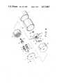
- FIG. 4is a pictorial view of the roller blind of FIG. 1 in disassembled position.
- the tube 1has an inner projection fitted in the recess in the outer periphery of the brake drum 18 with the intervention of the absorbing rubber 25.
- the both arcuate weights 22 with the brake shoes 23are rotatable about the respective pins 21 on the arm 19 and pulled to each other by a coil spring 24 behind the nut 20.
- the brake coil spring 6 of FIG. 1loosens when the rotator 7 or pins 11 rotates in the direction opposite to the arrow A of FIG. 2. Therefore, ring gear 13, planet gears 12, and sun gear 16 rotates together with tube 1, as one body, while the screen (not shown) is payed out to rotate tube in the direction opposite to the arrow A of FIG. 2.
- the brake shoe 23exerts a centrifugally braking force in proportion to the rotary speed of tube 1 on brake drum 18, so that the screen-winding speed is always reduced to the extent that the screen is quietly wound up even if the screen is fully payed out and then released.
- the teeth number of the ring gear, the sun gear, and the planet gear, the number of the brake shoes and the shape of the arcuate weightmay differ from those as seen in the drawings.
- the sound-absorbing member 25absorbs noise produced both by gearing engagement among ring gear 13, planet gears 12, and sun gear 16 and by frictional contact between brake drum 18 and brake shoes 23 with the result that screen-winding is always performed without noise.
Landscapes
- Engineering & Computer Science (AREA)
- Structural Engineering (AREA)
- Architecture (AREA)
- Civil Engineering (AREA)
- Operating, Guiding And Securing Of Roll- Type Closing Members (AREA)
Abstract
Description
Claims (5)
Applications Claiming Priority (2)
| Application Number | Priority Date | Filing Date | Title |
|---|---|---|---|
| JP1982061938UJPS58165188U (en) | 1982-04-30 | 1982-04-30 | Roll blind reduction gear |
| JP57-61938[U] | 1982-04-30 |
Publications (1)
| Publication Number | Publication Date |
|---|---|
| US4513805Atrue US4513805A (en) | 1985-04-30 |
Family
ID=13185620
Family Applications (1)
| Application Number | Title | Priority Date | Filing Date |
|---|---|---|---|
| US06/486,577Expired - LifetimeUS4513805A (en) | 1982-04-30 | 1983-04-19 | Decelerator for use in roller blinds |
Country Status (4)
| Country | Link |
|---|---|
| US (1) | US4513805A (en) |
| EP (1) | EP0093289B1 (en) |
| JP (1) | JPS58165188U (en) |
| DE (1) | DE3379065D1 (en) |
Cited By (63)
| Publication number | Priority date | Publication date | Assignee | Title |
|---|---|---|---|---|
| US4838333A (en)* | 1986-12-17 | 1989-06-13 | Mottura S.P.A. | Roller blind with a centrifugal-mass brake located outside the roller and an end support containing the brake |
| US5137073A (en)* | 1991-02-19 | 1992-08-11 | Teh Yor Industrial Co., Ltd. | Chain pulling device |
| AU676641B2 (en)* | 1994-08-17 | 1997-03-13 | Johnson Service Company | An actuating drive having a spring return feature |
| US5857553A (en)* | 1996-05-28 | 1999-01-12 | Somfy | Reducer with Oldham coupling |
| FR2787501A1 (en)* | 1998-12-21 | 2000-06-23 | Raymond Mitjavila | PROCESS FOR THE MANUFACTURE OF A MOTOR ASSEMBLY FOR OPERATING BLINDS, ROLLER SHUTTERS OR THE LIKE AND MOTOR ASSEMBLY OBTAINED BY THIS PROCESS |
| EP0922831A3 (en)* | 1997-12-12 | 2002-02-06 | Hunter Douglas Industries B.V. | Winding mechanism |
| GB2367087A (en)* | 2000-07-06 | 2002-03-27 | Newell Operating Co | Blind having variable resistance to movement |
| US20020174961A1 (en)* | 1999-03-23 | 2002-11-28 | Hunter Douglas Inc. | Modular transport system for coverings for architectural openings |
| US6570627B1 (en)* | 1999-10-08 | 2003-05-27 | Lg Electronics Inc. | Flat-type monitor |
| EP1327744A1 (en)* | 2001-12-18 | 2003-07-16 | MOTTURA S.p.A. | Roller blind device with centrifugal brake |
| US20030221799A1 (en)* | 2002-03-20 | 2003-12-04 | David Cross | Semi-cordless unbalanced spring driven blind system and methods for adjusting and making same |
| US6688438B2 (en)* | 2001-05-18 | 2004-02-10 | Siemens Building Technologies Ag | Actuator with a centrifugal brake |
| GB2397292A (en)* | 2003-01-15 | 2004-07-21 | Nifco Inc | Unidirectional brake for a winding mechanism |
| GB2398288A (en)* | 2003-02-12 | 2004-08-18 | Shinsei Seiki Co Ltd | Fire and smoke doorway screen apparatus for elevator |
| US20040216849A1 (en)* | 2001-10-22 | 2004-11-04 | 420820 Ontario Limited | Screen frame with integral roll screen compartment and improvements thereof |
| US20040261958A1 (en)* | 2002-10-07 | 2004-12-30 | Noboru Sugiyama | Automatic wind-up screen device |
| EP1591616A1 (en)* | 2004-04-26 | 2005-11-02 | Inalfa Roof Systems Group B.V. | Sunscreen assembly |
| US20050284589A1 (en)* | 2004-06-29 | 2005-12-29 | Dickinson Reynolds H Iii | Constant viscosity speed reducer |
| US7057360B1 (en)* | 2004-12-13 | 2006-06-06 | Mu-Chuan Hsu | Motor assembly for folding/unfolding foldable screen |
| US20060162878A1 (en)* | 2005-01-27 | 2006-07-27 | Paul Lin | Window blind with a resistance-providing unit |
| US20060283561A1 (en)* | 2003-09-05 | 2006-12-21 | Pierre-Lue Maumi | Device for controlling a venetian blind |
| US20070035828A1 (en)* | 2005-08-12 | 2007-02-15 | Guangzhou Grandview Crystal Screen Co., Ltd. | Decelerating and locking mechanism for a projection screen and the manually operated projection screen using the mechanism |
| US20070084570A1 (en)* | 2005-10-18 | 2007-04-19 | Gwo-Tsair Lin | Lift device of a blind |
| US20070181729A1 (en)* | 2005-12-02 | 2007-08-09 | Schuster Donald S | Re-spooling fishing reel |
| US20090078380A1 (en)* | 2007-09-26 | 2009-03-26 | Li-Ming Cheng | Damping apparatus for retraction and extension of window shades |
| WO2009052693A1 (en)* | 2007-10-24 | 2009-04-30 | Zhu, Xiaoying | A wind-up screen device |
| US20100018655A1 (en)* | 2006-12-08 | 2010-01-28 | Nichibei Co., Ltd. | Braking Apparatus for Blind |
| US20100243394A1 (en)* | 2009-03-30 | 2010-09-30 | Chun-Tang Lee | Drive mechanism |
| CN101625516B (en)* | 2008-07-10 | 2010-12-01 | 苏州璨宇光学有限公司 | Speed reducer and translucent screen reel releasing mechanism |
| US20110011543A1 (en)* | 2009-07-16 | 2011-01-20 | Zhu xiang-rong | Drum Driving Device for Window Shade |
| WO2011139355A1 (en)* | 2010-05-04 | 2011-11-10 | Homerun Holdings Corp. | Anti-reversible power spring apparatus and method |
| CN101672336B (en)* | 2008-09-08 | 2011-12-14 | 苏州璨宇光学有限公司 | Deceleration mechanism |
| US20120060276A1 (en)* | 2010-09-10 | 2012-03-15 | Heidlage John K | Height Adjustable Bed Framework with a Lift Chain and a Planetary Gear Train |
| US20120152470A1 (en)* | 2010-12-15 | 2012-06-21 | Chicology, Inc. | Decelerating device integrated with blind structure |
| US20120241111A1 (en)* | 2010-03-07 | 2012-09-27 | Jerzy Wolek | Mechanism for controlling the rotation of a roller blind winding roller having a spring drive |
| US8544525B2 (en) | 2011-05-13 | 2013-10-01 | Xiang-Rong Zhu | Bidirectionally operable/switchable pull cord mechanism for a window shade |
| JP2013542353A (en)* | 2010-11-10 | 2013-11-21 | ホームラン ホールディングス コーポレイション アン オハイオ コーポレイション | Modular non-reversible power spring apparatus and method |
| CN103615506A (en)* | 2013-11-22 | 2014-03-05 | 杭州欧卡索拉科技有限公司 | Double-shaft rotation sequence generator |
| US20140083631A1 (en)* | 2012-09-26 | 2014-03-27 | Taicang Kingfu Plastic Manufacture Co., Ltd. | Pull cord device and window covering including the same |
| US8763675B2 (en) | 2011-05-13 | 2014-07-01 | Xiang-Rong Zhu | Bead chain type pull cord mechanism for a window shade |
| US20140290875A1 (en)* | 2013-04-02 | 2014-10-02 | Hsueh Tsung Chen | Apparatus for a blind |
| US8851143B2 (en) | 2012-07-23 | 2014-10-07 | Xiang-Rong Zhu | Single pull rope driving device for a window shade |
| US20140332172A1 (en)* | 2013-05-13 | 2014-11-13 | Chung-Hsien Hsieh | Door Curtain Anti-Dropping Device for Electric Rolling Door |
| US20150136336A1 (en)* | 2013-11-15 | 2015-05-21 | Taicang Kingfu Plastic Manufacture Co., Ltd. | Cord-winding device for venetian blind |
| US20150176331A1 (en)* | 2013-12-20 | 2015-06-25 | Hsiao-Yin Chen | Damping Positioner |
| US20150275572A1 (en)* | 2014-03-28 | 2015-10-01 | Taicang Kingfu Plastic Manufacture Co., Ltd. | Window shade |
| US20150308188A1 (en)* | 2014-04-29 | 2015-10-29 | Macauto Industrial Co., Ltd. | Roll control device for a vehicle curtain |
| US9574396B2 (en) | 1997-11-04 | 2017-02-21 | Russell L. Hinckley, SR. | Systems for maintaining window covers |
| US20170130528A1 (en)* | 2015-08-18 | 2017-05-11 | Hunter Douglas Inc. | Brake assembly for a covering for an architectural opening |
| US20170138127A1 (en)* | 2008-08-26 | 2017-05-18 | Hunter Douglas Inc. | Roll-up retractable covering for architectural openings |
| US20170183904A1 (en)* | 2015-02-03 | 2017-06-29 | Hunter Douglas Industries Switzerland Gmbh | Window System Covering and Operating System |
| US20170211320A1 (en)* | 2016-01-22 | 2017-07-27 | Nien Made Enterprise Co., Ltd. | System and device for window covering system |
| US20170218703A1 (en)* | 2016-01-29 | 2017-08-03 | Nien Made Enterprise Co., Ltd. | Window covering system and displacement controlling device thereof |
| US20170226799A1 (en)* | 2016-02-04 | 2017-08-10 | Mechoshade Systems, Inc. | Quick release window shade system |
| US20180106100A1 (en)* | 2016-10-19 | 2018-04-19 | Hunter Douglas, Inc. | Dual mode architectural structure covering |
| US9963933B2 (en)* | 2015-03-12 | 2018-05-08 | Chin-Fu Chen | Blind body braking mechanism for non-cord window blind assembly |
| US10781635B2 (en)* | 2018-06-11 | 2020-09-22 | Chen Tian Co., Ltd. | Fast positioning structure of safe position limiting device of roller blind |
| US11261660B2 (en) | 2016-02-04 | 2022-03-01 | Mechoshade Systems, Llc | Magnetic quick release shade system |
| US11512531B2 (en)* | 2017-09-06 | 2022-11-29 | Tok, Inc. | Restriction mechanism for manual shutter device |
| CN115740628A (en)* | 2022-03-24 | 2023-03-07 | 东台立一工业技术有限公司 | Integrated edge rolling and chamfering equipment for manufacturing sliding bearing shaft sleeve |
| US11643865B2 (en) | 2018-01-23 | 2023-05-09 | Pella Corporation | Roller assembly and screen end retention features for a hidden screen assembly and a fenestration assembly |
| CN116368284A (en)* | 2020-11-11 | 2023-06-30 | 株式会社欧利生 | Centrifugal brake |
| US12000208B2 (en) | 2020-01-31 | 2024-06-04 | Pella Corporation | Integrated pleated screen assembly |
Families Citing this family (14)
| Publication number | Priority date | Publication date | Assignee | Title |
|---|---|---|---|---|
| US5117893A (en)* | 1985-08-07 | 1992-06-02 | Excel Shutter Systems, Inc. | Rolling shutter system |
| EP0330804A1 (en)* | 1988-03-01 | 1989-09-06 | MOTTURA S.p.A. | Roller blind, having a braking device with centrifugal masses arranged outside the roller and an end support including this braking device |
| US4884618A (en)* | 1988-08-05 | 1989-12-05 | Christopher Steeves | Roller blind mounting and rolling system |
| US5099906A (en)* | 1989-09-19 | 1992-03-31 | Metaco Co., Ltd. | Roller screen unit |
| IT1267206B1 (en)* | 1994-12-16 | 1997-01-28 | Mottura Spa | SUPPORT AND CONTROL DEVICE FOR A ROLLER BLIND. |
| EP0761925A1 (en)* | 1995-09-07 | 1997-03-12 | Becker Antriebe GmbH | Braking device for a smoke curtain, fire curtain or similar curtain |
| DE69820074T2 (en)* | 1997-07-16 | 2004-09-09 | Aktieselskabet Chr. Fabers Fabriker | ROLLER DEVICE FOR ROLLER BLINDS |
| AU782302B2 (en)* | 1997-07-16 | 2005-07-14 | A/S Chr. Fabers Fabriker | Winding mechanism for roller blinds |
| JP4994778B2 (en)* | 2006-10-13 | 2012-08-08 | トーソー株式会社 | Reduction device for solar radiation shielding member |
| DE102009028872A1 (en)* | 2009-08-26 | 2011-03-03 | Robert Bosch Gmbh | Electric motor, in particular starter motor for an internal combustion engine |
| DE102011050666B4 (en) | 2011-05-27 | 2014-06-12 | Achim Lienert | rewinder |
| JP6973790B2 (en)* | 2017-12-28 | 2021-12-01 | 株式会社Tok | Clutch mechanism and braking device |
| JP2020172780A (en)* | 2019-04-10 | 2020-10-22 | 中央発條株式会社 | Curtain body winding device |
| CN112607552B (en)* | 2020-12-18 | 2022-04-05 | 亿涛建设集团有限公司 | Multiple anti-falling hoisting mechanism |
Citations (12)
| Publication number | Priority date | Publication date | Assignee | Title |
|---|---|---|---|---|
| US219747A (en)* | 1879-09-16 | Improvement in curtain-fixtures | ||
| FR519735A (en)* | 1919-12-13 | 1921-06-14 | Alfred Coindet | Brake for awning mechanism |
| US1494503A (en)* | 1922-09-11 | 1924-05-20 | Rackham George John | Change-speed gear for automobile engines |
| FR756882A (en)* | 1932-09-13 | 1933-12-16 | Roudayre Et Cie | Simplified gear change device without clutch, adaptable to the rear hub of a motor-bike or motorcycle |
| US2332588A (en)* | 1940-10-07 | 1943-10-26 | Borg Warner | Variable transmission |
| US2892521A (en)* | 1957-07-08 | 1959-06-30 | Bendix Aviat Corp | Two-speed transmission for vehicles |
| FR1366457A (en)* | 1962-08-18 | 1964-07-10 | Fichtel & Sachs Ag | Two-speed transmission hub with automatically controlled gear change according to the travel speed of the bicycle |
| US3285089A (en)* | 1964-04-13 | 1966-11-15 | Nihon Bunka Roller Shutter Com | Drive mechanism for a shutter winding device |
| US3388617A (en)* | 1962-10-04 | 1968-06-18 | Blanche G Nelson | Automatic variable speed bicycle transmission |
| US4059339A (en)* | 1976-01-08 | 1977-11-22 | Knox Manufacturing Co. | Brake mechanism for motor driven projection screen |
| US4172563A (en)* | 1975-03-19 | 1979-10-30 | Siemens Aktiengesellschaft | Shut-off unit in a drive unit for awnings and roller blinds |
| JPS5536185A (en)* | 1979-08-16 | 1980-03-13 | Honda Motor Co Ltd | Automatic speed change gear of vehicle |
Family Cites Families (8)
| Publication number | Priority date | Publication date | Assignee | Title |
|---|---|---|---|---|
| GB156500A (en)* | 1919-12-13 | 1921-06-30 | Alfred Coindet | Improvements in and relating to blinds |
| GB166901A (en)* | 1920-07-24 | 1922-10-25 | L Ph Hemmer Ges Mit Beschraenk | Improvements in friction clutches |
| GB238426A (en)* | 1924-11-19 | 1925-08-20 | Reginald Harold Tutty | An internal check action to a spring blind roller |
| CH259639A (en)* | 1947-12-03 | 1949-01-31 | Eisen Und Stahlwerke Oehler & | Tow brake for ski lift. |
| US3618721A (en)* | 1970-08-24 | 1971-11-09 | Richard C Hare | One-way clutch |
| JPS4736027U (en)* | 1971-05-06 | 1972-12-21 | ||
| US4188992A (en)* | 1977-12-07 | 1980-02-19 | Segerljung Bo V | Brake device for rotatable and spring loaded rods, foil or cloth material being attachable to said rods |
| JPS5828155Y2 (en)* | 1980-01-22 | 1983-06-18 | メタコ企業株式会社 | Roll screen hoisting braking device |
- 1982
- 1982-04-30JPJP1982061938Upatent/JPS58165188U/enactiveGranted
- 1983
- 1983-04-13EPEP83103564Apatent/EP0093289B1/ennot_activeExpired
- 1983-04-13DEDE8383103564Tpatent/DE3379065D1/ennot_activeExpired
- 1983-04-19USUS06/486,577patent/US4513805A/ennot_activeExpired - Lifetime
Patent Citations (12)
| Publication number | Priority date | Publication date | Assignee | Title |
|---|---|---|---|---|
| US219747A (en)* | 1879-09-16 | Improvement in curtain-fixtures | ||
| FR519735A (en)* | 1919-12-13 | 1921-06-14 | Alfred Coindet | Brake for awning mechanism |
| US1494503A (en)* | 1922-09-11 | 1924-05-20 | Rackham George John | Change-speed gear for automobile engines |
| FR756882A (en)* | 1932-09-13 | 1933-12-16 | Roudayre Et Cie | Simplified gear change device without clutch, adaptable to the rear hub of a motor-bike or motorcycle |
| US2332588A (en)* | 1940-10-07 | 1943-10-26 | Borg Warner | Variable transmission |
| US2892521A (en)* | 1957-07-08 | 1959-06-30 | Bendix Aviat Corp | Two-speed transmission for vehicles |
| FR1366457A (en)* | 1962-08-18 | 1964-07-10 | Fichtel & Sachs Ag | Two-speed transmission hub with automatically controlled gear change according to the travel speed of the bicycle |
| US3388617A (en)* | 1962-10-04 | 1968-06-18 | Blanche G Nelson | Automatic variable speed bicycle transmission |
| US3285089A (en)* | 1964-04-13 | 1966-11-15 | Nihon Bunka Roller Shutter Com | Drive mechanism for a shutter winding device |
| US4172563A (en)* | 1975-03-19 | 1979-10-30 | Siemens Aktiengesellschaft | Shut-off unit in a drive unit for awnings and roller blinds |
| US4059339A (en)* | 1976-01-08 | 1977-11-22 | Knox Manufacturing Co. | Brake mechanism for motor driven projection screen |
| JPS5536185A (en)* | 1979-08-16 | 1980-03-13 | Honda Motor Co Ltd | Automatic speed change gear of vehicle |
Cited By (110)
| Publication number | Priority date | Publication date | Assignee | Title |
|---|---|---|---|---|
| US4838333A (en)* | 1986-12-17 | 1989-06-13 | Mottura S.P.A. | Roller blind with a centrifugal-mass brake located outside the roller and an end support containing the brake |
| US5137073A (en)* | 1991-02-19 | 1992-08-11 | Teh Yor Industrial Co., Ltd. | Chain pulling device |
| AU676641B2 (en)* | 1994-08-17 | 1997-03-13 | Johnson Service Company | An actuating drive having a spring return feature |
| US5857553A (en)* | 1996-05-28 | 1999-01-12 | Somfy | Reducer with Oldham coupling |
| US9574396B2 (en) | 1997-11-04 | 2017-02-21 | Russell L. Hinckley, SR. | Systems for maintaining window covers |
| US6666252B2 (en) | 1997-12-12 | 2003-12-23 | Hunter Douglas Industries Bv | Winding mechanism |
| EP1405982A3 (en)* | 1997-12-12 | 2004-06-23 | Hunter Douglas Industries B.V. | A winding mechanism for an architectural covering |
| EP0922831A3 (en)* | 1997-12-12 | 2002-02-06 | Hunter Douglas Industries B.V. | Winding mechanism |
| US6443210B1 (en) | 1997-12-12 | 2002-09-03 | Hunter Douglas Industries Bv | Winding mechanism |
| FR2787501A1 (en)* | 1998-12-21 | 2000-06-23 | Raymond Mitjavila | PROCESS FOR THE MANUFACTURE OF A MOTOR ASSEMBLY FOR OPERATING BLINDS, ROLLER SHUTTERS OR THE LIKE AND MOTOR ASSEMBLY OBTAINED BY THIS PROCESS |
| EP1013872A1 (en)* | 1998-12-21 | 2000-06-28 | Raymond Mitjavila | Manufacturing process for a motor assembly for driving blinds, roller shutters or the like and motor assembly obtained by said manufacturing process |
| US7802608B2 (en) | 1999-03-23 | 2010-09-28 | Hunter Douglas Inc. | Modular transport system for coverings for architectural openings |
| US20080093034A1 (en)* | 1999-03-23 | 2008-04-24 | Hunter Douglas Inc. | Modular transport system for coverings for architectural openings |
| US7311133B2 (en) | 1999-03-23 | 2007-12-25 | Hunter Douglas, Inc. | Lift and tilt station for a covering for an architectural opening |
| US20020174961A1 (en)* | 1999-03-23 | 2002-11-28 | Hunter Douglas Inc. | Modular transport system for coverings for architectural openings |
| US20110000628A1 (en)* | 1999-03-23 | 2011-01-06 | Hunter Douglas Inc. | Modular transport system for coverings for architectural openings |
| US8230896B2 (en) | 1999-03-23 | 2012-07-31 | Hunter Douglas Inc | Modular transport system for coverings for architectural openings |
| US6968884B2 (en)* | 1999-03-23 | 2005-11-29 | Hunter Douglas Inc. | Modular transport system for coverings for architectural openings |
| US20060000561A1 (en)* | 1999-03-23 | 2006-01-05 | Hunter Douglas Inc. | Modular transport system for coverings for architectural openings |
| US6570627B1 (en)* | 1999-10-08 | 2003-05-27 | Lg Electronics Inc. | Flat-type monitor |
| GB2367087A (en)* | 2000-07-06 | 2002-03-27 | Newell Operating Co | Blind having variable resistance to movement |
| US6688438B2 (en)* | 2001-05-18 | 2004-02-10 | Siemens Building Technologies Ag | Actuator with a centrifugal brake |
| US20040216849A1 (en)* | 2001-10-22 | 2004-11-04 | 420820 Ontario Limited | Screen frame with integral roll screen compartment and improvements thereof |
| US7210513B2 (en)* | 2001-10-22 | 2007-05-01 | 420820 Ontario Limited | Screen frame with integral roll screen compartment and improvements thereof |
| EP1327744A1 (en)* | 2001-12-18 | 2003-07-16 | MOTTURA S.p.A. | Roller blind device with centrifugal brake |
| US6854503B2 (en)* | 2002-03-20 | 2005-02-15 | Rollease, Inc. | Semi-cordless unbalanced spring driven blind system and methods for adjusting and making same |
| US20030221799A1 (en)* | 2002-03-20 | 2003-12-04 | David Cross | Semi-cordless unbalanced spring driven blind system and methods for adjusting and making same |
| US6938667B2 (en)* | 2002-10-07 | 2005-09-06 | Seiki Juko Co., Ltd. | Automatic wind-up screen device |
| US20040261958A1 (en)* | 2002-10-07 | 2004-12-30 | Noboru Sugiyama | Automatic wind-up screen device |
| GB2397292A (en)* | 2003-01-15 | 2004-07-21 | Nifco Inc | Unidirectional brake for a winding mechanism |
| GB2398288A (en)* | 2003-02-12 | 2004-08-18 | Shinsei Seiki Co Ltd | Fire and smoke doorway screen apparatus for elevator |
| US20060283561A1 (en)* | 2003-09-05 | 2006-12-21 | Pierre-Lue Maumi | Device for controlling a venetian blind |
| US7360574B2 (en)* | 2003-09-05 | 2008-04-22 | Mariton S.A. | Device for controlling a venetian blind |
| EP1591616A1 (en)* | 2004-04-26 | 2005-11-02 | Inalfa Roof Systems Group B.V. | Sunscreen assembly |
| US20050284589A1 (en)* | 2004-06-29 | 2005-12-29 | Dickinson Reynolds H Iii | Constant viscosity speed reducer |
| US20110174450A1 (en)* | 2004-06-29 | 2011-07-21 | Dickinson Iii Reynolds H | Constant viscosity speed reducer |
| US7918264B2 (en)* | 2004-06-29 | 2011-04-05 | Dickinson Iii Reynolds H | Constant viscosity speed reducer |
| US20060125432A1 (en)* | 2004-12-13 | 2006-06-15 | Mu-Chuan Hsu | Motor assembly for folding/unfolding foldable screen |
| US7057360B1 (en)* | 2004-12-13 | 2006-06-06 | Mu-Chuan Hsu | Motor assembly for folding/unfolding foldable screen |
| US20060162878A1 (en)* | 2005-01-27 | 2006-07-27 | Paul Lin | Window blind with a resistance-providing unit |
| US20070035828A1 (en)* | 2005-08-12 | 2007-02-15 | Guangzhou Grandview Crystal Screen Co., Ltd. | Decelerating and locking mechanism for a projection screen and the manually operated projection screen using the mechanism |
| US7706067B2 (en)* | 2005-08-12 | 2010-04-27 | Guangzhou Grandview Crystal Screen Co., Ltd. | Decelerating and locking mechanism for a projection screen and the manually operated projection screen using the mechanism |
| US20070084570A1 (en)* | 2005-10-18 | 2007-04-19 | Gwo-Tsair Lin | Lift device of a blind |
| US20070181729A1 (en)* | 2005-12-02 | 2007-08-09 | Schuster Donald S | Re-spooling fishing reel |
| US20100018655A1 (en)* | 2006-12-08 | 2010-01-28 | Nichibei Co., Ltd. | Braking Apparatus for Blind |
| US8051960B2 (en)* | 2006-12-08 | 2011-11-08 | Nichibei Co., Ltd. | Braking apparatus for blind |
| AU2007335555B2 (en)* | 2006-12-18 | 2013-07-18 | Nichibei Co., Ltd. | Braking apparatus for blind |
| US20090078380A1 (en)* | 2007-09-26 | 2009-03-26 | Li-Ming Cheng | Damping apparatus for retraction and extension of window shades |
| GB2466174B (en)* | 2007-10-24 | 2013-03-13 | Xiaoying Zhu | Curtain |
| WO2009052693A1 (en)* | 2007-10-24 | 2009-04-30 | Zhu, Xiaoying | A wind-up screen device |
| GB2466174A (en)* | 2007-10-24 | 2010-06-16 | Xiaoying Zhu | A wind-up screen device |
| US8281846B2 (en) | 2007-10-24 | 2012-10-09 | Xiangrong Zhu | Curtain |
| CN101625516B (en)* | 2008-07-10 | 2010-12-01 | 苏州璨宇光学有限公司 | Speed reducer and translucent screen reel releasing mechanism |
| US10724298B2 (en)* | 2008-08-26 | 2020-07-28 | Hunter Douglas Inc. | Roll-up retractable covering for architectural openings |
| US20170138127A1 (en)* | 2008-08-26 | 2017-05-18 | Hunter Douglas Inc. | Roll-up retractable covering for architectural openings |
| CN101672336B (en)* | 2008-09-08 | 2011-12-14 | 苏州璨宇光学有限公司 | Deceleration mechanism |
| US20100243394A1 (en)* | 2009-03-30 | 2010-09-30 | Chun-Tang Lee | Drive mechanism |
| US8357066B2 (en) | 2009-03-30 | 2013-01-22 | Aixin Technologies, Llc | Drive mechanism |
| US8365802B2 (en) | 2009-07-16 | 2013-02-05 | Zhu xiang-rong | Drum driving device for window shade |
| US20110011543A1 (en)* | 2009-07-16 | 2011-01-20 | Zhu xiang-rong | Drum Driving Device for Window Shade |
| US20120241111A1 (en)* | 2010-03-07 | 2012-09-27 | Jerzy Wolek | Mechanism for controlling the rotation of a roller blind winding roller having a spring drive |
| AU2010347808B2 (en)* | 2010-03-07 | 2016-11-10 | Franc Gardiner Sp. Z.O.O. | Mechanism controlling the rotation of roller blinds winding roller with a spring drive |
| US20140103157A1 (en)* | 2010-03-07 | 2014-04-17 | Jerzy Wolek | Mechanism for controlling the rotation of a roller blind winding roller having a spring drive |
| US9371690B2 (en)* | 2010-03-07 | 2016-06-21 | Jerzy Wolek | Mechanism for controlling the rotation of a roller blind winding roller having a spring drive |
| WO2011139355A1 (en)* | 2010-05-04 | 2011-11-10 | Homerun Holdings Corp. | Anti-reversible power spring apparatus and method |
| US9737149B2 (en)* | 2010-09-10 | 2017-08-22 | Hill-Rom Services, Inc. | Height adjustable bed framework with a lift chain and a planetary gear train |
| US20120060276A1 (en)* | 2010-09-10 | 2012-03-15 | Heidlage John K | Height Adjustable Bed Framework with a Lift Chain and a Planetary Gear Train |
| JP2013542353A (en)* | 2010-11-10 | 2013-11-21 | ホームラン ホールディングス コーポレイション アン オハイオ コーポレイション | Modular non-reversible power spring apparatus and method |
| US20120152470A1 (en)* | 2010-12-15 | 2012-06-21 | Chicology, Inc. | Decelerating device integrated with blind structure |
| US8544525B2 (en) | 2011-05-13 | 2013-10-01 | Xiang-Rong Zhu | Bidirectionally operable/switchable pull cord mechanism for a window shade |
| US8763675B2 (en) | 2011-05-13 | 2014-07-01 | Xiang-Rong Zhu | Bead chain type pull cord mechanism for a window shade |
| US8851143B2 (en) | 2012-07-23 | 2014-10-07 | Xiang-Rong Zhu | Single pull rope driving device for a window shade |
| US8893763B2 (en)* | 2012-09-26 | 2014-11-25 | Taicang Kingfu Plastic Manufacture Co., Ltd. | Pull cord device and window covering including the same |
| US20140083631A1 (en)* | 2012-09-26 | 2014-03-27 | Taicang Kingfu Plastic Manufacture Co., Ltd. | Pull cord device and window covering including the same |
| US20140290875A1 (en)* | 2013-04-02 | 2014-10-02 | Hsueh Tsung Chen | Apparatus for a blind |
| US20140332172A1 (en)* | 2013-05-13 | 2014-11-13 | Chung-Hsien Hsieh | Door Curtain Anti-Dropping Device for Electric Rolling Door |
| US9376864B2 (en)* | 2013-05-13 | 2016-06-28 | Chung-Hsien Hsieh | Door curtain anti-dropping device for electric rolling door |
| US9127500B2 (en)* | 2013-11-15 | 2015-09-08 | Taicang Kingfu Plastic Manufacture Co., Ltd. | Cord-winding device for venetian blind |
| US20150136336A1 (en)* | 2013-11-15 | 2015-05-21 | Taicang Kingfu Plastic Manufacture Co., Ltd. | Cord-winding device for venetian blind |
| CN103615506A (en)* | 2013-11-22 | 2014-03-05 | 杭州欧卡索拉科技有限公司 | Double-shaft rotation sequence generator |
| CN103615506B (en)* | 2013-11-22 | 2016-02-17 | 杭州欧卡索拉科技有限公司 | Double-shaft rotation sequence generator |
| US9194176B2 (en)* | 2013-12-20 | 2015-11-24 | Hsiao-Yin Chen | Damping positioner |
| US20150176331A1 (en)* | 2013-12-20 | 2015-06-25 | Hsiao-Yin Chen | Damping Positioner |
| US20150275572A1 (en)* | 2014-03-28 | 2015-10-01 | Taicang Kingfu Plastic Manufacture Co., Ltd. | Window shade |
| US9689202B2 (en)* | 2014-04-29 | 2017-06-27 | Macauto Industrial Co., Ltd. | Roll control device for a vehicle curtain |
| US20150308188A1 (en)* | 2014-04-29 | 2015-10-29 | Macauto Industrial Co., Ltd. | Roll control device for a vehicle curtain |
| US20170183904A1 (en)* | 2015-02-03 | 2017-06-29 | Hunter Douglas Industries Switzerland Gmbh | Window System Covering and Operating System |
| US10626667B2 (en)* | 2015-02-03 | 2020-04-21 | Hunter Dougls Industries Switzerland GmbH | Window system covering and operating system |
| US9963933B2 (en)* | 2015-03-12 | 2018-05-08 | Chin-Fu Chen | Blind body braking mechanism for non-cord window blind assembly |
| US10450798B2 (en)* | 2015-08-18 | 2019-10-22 | Hunter Douglas Inc. | Brake assembly for a covering for an architectural opening |
| US10890028B2 (en) | 2015-08-18 | 2021-01-12 | Hunter Douglas Inc. | Brake assembly for a covering for an architectural opening |
| US20170130528A1 (en)* | 2015-08-18 | 2017-05-11 | Hunter Douglas Inc. | Brake assembly for a covering for an architectural opening |
| US20170211320A1 (en)* | 2016-01-22 | 2017-07-27 | Nien Made Enterprise Co., Ltd. | System and device for window covering system |
| US10451145B2 (en)* | 2016-01-22 | 2019-10-22 | Nien Made Enterprise Co., Ltd. | System and device for window covering system |
| US10731408B2 (en)* | 2016-01-29 | 2020-08-04 | Nien Made Enterprise Co., Ltd. | Window covering system and displacement controlling device thereof |
| US20170218703A1 (en)* | 2016-01-29 | 2017-08-03 | Nien Made Enterprise Co., Ltd. | Window covering system and displacement controlling device thereof |
| US10472887B2 (en)* | 2016-02-04 | 2019-11-12 | Mechoshade Systems, Llc. | Quick release window shade system |
| US20170226799A1 (en)* | 2016-02-04 | 2017-08-10 | Mechoshade Systems, Inc. | Quick release window shade system |
| US11261660B2 (en) | 2016-02-04 | 2022-03-01 | Mechoshade Systems, Llc | Magnetic quick release shade system |
| US20180106100A1 (en)* | 2016-10-19 | 2018-04-19 | Hunter Douglas, Inc. | Dual mode architectural structure covering |
| US10655384B2 (en)* | 2016-10-19 | 2020-05-19 | Hunter Douglas, Inc. | Dual mode architectural structure covering |
| US11512531B2 (en)* | 2017-09-06 | 2022-11-29 | Tok, Inc. | Restriction mechanism for manual shutter device |
| US11993983B2 (en) | 2017-09-06 | 2024-05-28 | Tok, Inc. | Restriction mechanism for suspended sliding door device |
| US12173553B2 (en) | 2018-01-23 | 2024-12-24 | Pella Corporation | Screen edge retention and screen rethreading features for a hidden screen assembly and a fenestration assembly |
| US11643865B2 (en) | 2018-01-23 | 2023-05-09 | Pella Corporation | Roller assembly and screen end retention features for a hidden screen assembly and a fenestration assembly |
| US11643864B2 (en) | 2018-01-23 | 2023-05-09 | Pella Corporation | Screen edge retention and screen rethreading features for a hidden screen assembly and a fenestration assembly |
| US10781635B2 (en)* | 2018-06-11 | 2020-09-22 | Chen Tian Co., Ltd. | Fast positioning structure of safe position limiting device of roller blind |
| US12000208B2 (en) | 2020-01-31 | 2024-06-04 | Pella Corporation | Integrated pleated screen assembly |
| CN116368284A (en)* | 2020-11-11 | 2023-06-30 | 株式会社欧利生 | Centrifugal brake |
| CN115740628A (en)* | 2022-03-24 | 2023-03-07 | 东台立一工业技术有限公司 | Integrated edge rolling and chamfering equipment for manufacturing sliding bearing shaft sleeve |
Also Published As
| Publication number | Publication date |
|---|---|
| EP0093289B1 (en) | 1989-01-25 |
| EP0093289A2 (en) | 1983-11-09 |
| JPH0145353Y2 (en) | 1989-12-27 |
| DE3379065D1 (en) | 1989-03-02 |
| JPS58165188U (en) | 1983-11-02 |
| EP0093289A3 (en) | 1985-10-23 |
Similar Documents
| Publication | Publication Date | Title |
|---|---|---|
| US4513805A (en) | Decelerator for use in roller blinds | |
| ES2306866T3 (en) | CLUTCH OF ROLLABLE DISPLAY WITH INTERNAL GEARS. | |
| US4498517A (en) | Braking device for use in a roller blind | |
| JP4538836B2 (en) | Equipment for attaching tension cables, especially bundles of multiple tension cables in cable-type shoes | |
| EP1009904B1 (en) | Winding mechanism for roller blinds | |
| CN104806148B (en) | Rolling control mechanism of automobile rolling screen device | |
| US4848433A (en) | Two-speed reducing mechanism for controlling closure devices with adjustable luminosity, of the type such as blinds with orientable slats and the like | |
| US4487245A (en) | Torque-adjusting device for use in a roller blind | |
| EP0210381A2 (en) | Screen-positioning device for use in roll blind | |
| JPH11501375A (en) | Actuator for shielding device | |
| KR910003410B1 (en) | Roller blinds with adjustable speed | |
| EP0180832B1 (en) | A screen-locking device for use in roll blinds | |
| US3139241A (en) | Fishing reel clutch | |
| US4343442A (en) | Arrangement in fishing reels for compensating for the line retrieval in relation to the brake force on line withdrawal | |
| JPH11513560A (en) | Drive unit with adjustable torque | |
| US20240151103A1 (en) | Adjustable resistance tail plug | |
| JP2708240B2 (en) | Roll screen braking device | |
| US3642231A (en) | Brake mechanism for fishing reels | |
| EP0330804A1 (en) | Roller blind, having a braking device with centrifugal masses arranged outside the roller and an end support including this braking device | |
| EP2807322A1 (en) | Window treatment operating apparatus with cycloidal drive | |
| US2284521A (en) | Wind motor with variable pitch automatic speed control | |
| JP7576420B2 (en) | Roller blinds | |
| TWM561128U (en) | Rolling device of window covering | |
| JP3895619B2 (en) | Fishing reel | |
| JPS5910428Y2 (en) | Ratchet mechanism |
Legal Events
| Date | Code | Title | Description |
|---|---|---|---|
| AS | Assignment | Owner name:TOSO KABUSHIKI KAISHA 4-9, SHINKAWA 1-CHOME, CHUO- Free format text:ASSIGNMENT OF ASSIGNORS INTEREST.;ASSIGNOR:MASE, RYOICHI;REEL/FRAME:004120/0607 Effective date:19830325 | |
| STCF | Information on status: patent grant | Free format text:PATENTED CASE | |
| FEPP | Fee payment procedure | Free format text:PAYOR NUMBER ASSIGNED (ORIGINAL EVENT CODE: ASPN); ENTITY STATUS OF PATENT OWNER: SMALL ENTITY | |
| FPAY | Fee payment | Year of fee payment:4 | |
| FEPP | Fee payment procedure | Free format text:PAYOR NUMBER ASSIGNED (ORIGINAL EVENT CODE: ASPN); ENTITY STATUS OF PATENT OWNER: SMALL ENTITY Free format text:PAYER NUMBER DE-ASSIGNED (ORIGINAL EVENT CODE: RMPN); ENTITY STATUS OF PATENT OWNER: SMALL ENTITY | |
| FPAY | Fee payment | Year of fee payment:8 | |
| FEPP | Fee payment procedure | Free format text:PAYOR NUMBER ASSIGNED (ORIGINAL EVENT CODE: ASPN); ENTITY STATUS OF PATENT OWNER: SMALL ENTITY Free format text:PAYER NUMBER DE-ASSIGNED (ORIGINAL EVENT CODE: RMPN); ENTITY STATUS OF PATENT OWNER: SMALL ENTITY | |
| FPAY | Fee payment | Year of fee payment:12 |