US4513744A - Surgical compression plate - Google Patents
Surgical compression plateDownload PDFInfo
- Publication number
- US4513744A US4513744AUS06/441,633US44163382AUS4513744AUS 4513744 AUS4513744 AUS 4513744AUS 44163382 AUS44163382 AUS 44163382AUS 4513744 AUS4513744 AUS 4513744A
- Authority
- US
- United States
- Prior art keywords
- screw
- hole
- plate
- slope
- bone
- Prior art date
- Legal status (The legal status is an assumption and is not a legal conclusion. Google has not performed a legal analysis and makes no representation as to the accuracy of the status listed.)
- Expired - Fee Related
Links
Images


Classifications
- A—HUMAN NECESSITIES
- A61—MEDICAL OR VETERINARY SCIENCE; HYGIENE
- A61B—DIAGNOSIS; SURGERY; IDENTIFICATION
- A61B17/00—Surgical instruments, devices or methods
- A61B17/56—Surgical instruments or methods for treatment of bones or joints; Devices specially adapted therefor
- A61B17/58—Surgical instruments or methods for treatment of bones or joints; Devices specially adapted therefor for osteosynthesis, e.g. bone plates, screws or setting implements
- A61B17/68—Internal fixation devices, including fasteners and spinal fixators, even if a part thereof projects from the skin
- A61B17/80—Cortical plates, i.e. bone plates; Instruments for holding or positioning cortical plates, or for compressing bones attached to cortical plates
- A61B17/8004—Cortical plates, i.e. bone plates; Instruments for holding or positioning cortical plates, or for compressing bones attached to cortical plates with means for distracting or compressing the bone or bones
- A61B17/8014—Cortical plates, i.e. bone plates; Instruments for holding or positioning cortical plates, or for compressing bones attached to cortical plates with means for distracting or compressing the bone or bones the extension or compression force being caused by interaction of the plate hole and the screws
Definitions
- This inventionrelates to compression plates for use in reducing bone fractures.
- itrelates to an improved compression plate which is easier for the surgeon to use and reduces the danger of placing excessive load on the screws used to secure the plate.
- the compression plate described and claimed in U.S. Pat. No. Re 28,841has one or more elongated holes or slots for receiving screws, preferably round headed screws, in which the sides of the slots are sloped inwardly and downwardly in cylindrical configuration so that when the screw is advanced into the bone the bone fragments are brought together by a camming action and then compressed. Further description of this and other styles of compression plates may be found in the following references:
- a compression platehaving elongated holes or slots whose side surfaces are sloped inwardly and downwardly with variable slope, bowing outwardly in the direction of the hole opening or longitudinal screw displacement, the slope being designed to maintain constant torque or gradually increasing torque during the longitudinal displacement and compression stages, with a sudden, abrupt increase in torque as the screw is seated; or, preferably, with a diminution of the torque toward the end of the compression stage followed by a sudden increase as the screw is seated.
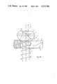
- FIGS. 1A to 1Care views taken in side elevation and partly in vertical section of a plate according to the invention, together with a screw in various positions corresponding to the longitudinal displacement, compression and seating stages.
- FIG. 2is a curve of the points of tangency of a spherical screw head and the wall of the elongated hole or slot in a plate according to the invention.
- FIG. 3is a diagram showing the relationship of forces in the longitudinal displacement phase with a system according to the invention.
- FIG. 4is a diagram showing the relationship of forces toward the end of the compression phase with a system according to the invention.
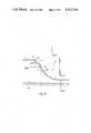
- FIG. 5is a graph of torque and displacement comparing a plate according to the invention with a more conventional plate.
- FIG. 6is a diagram representing, in a simplified way, the locus of the center of a screw head used with a plate of preferred design according to the invention.
- FIG. 7is a diagrammatic view of a plate according to the invention, illustrating the initial and final positions of the screw.
- FIG. 8is a graph of torque vs. displacement for a plate of preferred design according to the invention.
- a system according to the inventioncomprises a plate 1 having an elongated hole or slot 7 and a screw 3 having a head 5 which is preferably, but not necessarily hemispheric in shape.
- the side walls of the slotare sloped inwardly and downwardly to provide a surface 11 against which the bottom surface of the screw bears as it is advanced vertically downwardly into the bone (not shown).
- the effect of this plate/screw contactis to move the screw longitudinally along the axis of the plate.
- FIG. 1Ashows the screw at the beginning of its travel.
- FIG. 1Bshows the screw advanced downwardly into the bone and displaced longitudinally to the right.
- FIG. 1Cshows the screw seated in the slot. It will be observed that the screw in FIG. 1C can still have longitudinal displacement. Thus the effect of other screws in the same plate can be provided for.
- the travel of the screw longitudinallyis not a straight line but is a combination of intersecting straight lines or a curve which bows outwardly in the direction of longitudinal displacement.
- Thiscan be observed from FIGS. 1A-1C where the locus of a point at the center of the screw head, as displacement occurs, is shown by line 13.
- the slope of curve 13is intended as illustrative rather than definitive.
- FIG. 2is a graph of the points of contact of the plate and screw in a vertical plane through the axis of the plate. As shown in FIG. 2 in phase A the slope of the curve at a point of contact is about 43°; in phase B it increases and at the point shown is 63°. The result of this in terms of forces in the two major directions is shown in FIGS. 3 and 4. In this particular case the relationship between F XA , the force in the X direction in phase A, and F XB , the force in the X direction in phase B is
- FIGS. 3 and 4is a function of the friction between screw and plate.
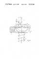
- the movement of the screw headcan be considered in terms of two straight lines of different slope. This is illustrated in FIG. 6 where the screw moves from the initial point of contact A along an upper path 30 which makes an angle ⁇ 1 with the horizontal to a point (X 1 , Y 1 ). At the lower section of its travel, from a point (X 2 , Y 2 ) to point B, the path 31 of the screw head is more nearly vertical, making an angle ⁇ 2 with the horizontal. In some instances the points (X 1 , Y 1 ) and (X 2 , X 2 ) may coincide, i.e., the travel may be two intersecting straight lines.
- the chief constraints to be consideredare minimum and maximum plate thickness, minimum and maximum horizontal travel and the minimum vertical travel for the terminal portion of the screw travel.
- the plate thicknessis obviously determined by the particular application, but typically is from 3.6 to 3.9 mm.
- Horizontal travelalso depends on the purpose but is typically 1-2 mm.
- the minimum vertical travelwill depend on screw size and pitch but should conform to at least 270° of screw rotation, or in general at least 1.27 mm.
- FRtravel length (of the center of the screw head)/contact length, which is a measure of the plate abrasion.
- points D and Erepresent the initial and final contact points (or contact lines) between the plate and the screw head, R s being the radius of the screw head (shown greatly foreshortened in FIG. 6).
- the ratio referred to, designated FRis: ##EQU2## where DE is the distance between D and E, t is the total vertical travel, and ⁇ is the maximum horizontal travel.
- corner sharpnessthe abruptness of transition from the initial angle, to the terminal angle.
- the travel pathis represented by a third order polynomial.
- the following program(Fortran 77) has been developed for obtaining the maximum final angle and minimum initial angle and the other parameters of the system, namely, the location of the screw head at the initial and final positions relative to a chosen origin (R 1 , R 2 ), the total horizontal travel, the total vertical travel, the vertical travel in the steep portion (YC), the FR factor, the SH factor and the plate thickness, give limiting values for horizontal travel (minimum and maximum) minimum vertical travel for the steep portion, maximum FR, maximum SH, and minimum and maximum plate thickness.
- the radii R 1 and R 2 at the initial and final positions of the screware taken from an arbitrary origin at the level of the bottom of the screw head when fully seated and at a point 7.25 mm from the center of the screw when fully seated. Any other convenient origin could equally well be chosen.
- Distances a, b and crepresent the longitudinal distances along the axis of the plate corresponding to displacement, compression and seating.
- Distances a' and b'represent travel of the center of the screwhead on plates a and b.
- the point c'is the position of the center of the screwhead when the screwhead is seated.
Landscapes
- Health & Medical Sciences (AREA)
- Orthopedic Medicine & Surgery (AREA)
- Surgery (AREA)
- Life Sciences & Earth Sciences (AREA)
- Heart & Thoracic Surgery (AREA)
- Nuclear Medicine, Radiotherapy & Molecular Imaging (AREA)
- Engineering & Computer Science (AREA)
- Biomedical Technology (AREA)
- Neurology (AREA)
- Medical Informatics (AREA)
- Molecular Biology (AREA)
- Animal Behavior & Ethology (AREA)
- General Health & Medical Sciences (AREA)
- Public Health (AREA)
- Veterinary Medicine (AREA)
- Surgical Instruments (AREA)
Abstract
Description
F.sub.XA /F.sub.XA =6.4.
Rc=[(t+δ)/2]
Y=C.sub.1 X.sup.3 +C.sub.2 X.sup.2 +C.sub.3 X+C.sub.4
d.sup.2 y/dx.sup.2 =(tan θ.sub.1 -tan θ.sub.2)
Claims (9)
Priority Applications (1)
| Application Number | Priority Date | Filing Date | Title |
|---|---|---|---|
| GB08330347AGB2132487B (en) | 1982-11-15 | 1983-11-14 | Surgical compression plate system |
Applications Claiming Priority (2)
| Application Number | Priority Date | Filing Date | Title |
|---|---|---|---|
| CH1773/81ACH650915A5 (en) | 1981-03-16 | 1981-03-16 | DEVICE FOR STABILIZING THE AREA OF A BONE BREAK OR OSTEOTOMY. |
| CH17731/81 | 1981-03-16 |
Related Parent Applications (1)
| Application Number | Title | Priority Date | Filing Date |
|---|---|---|---|
| US06358389Continuation-In-Part | 1982-03-15 |
Publications (1)
| Publication Number | Publication Date |
|---|---|
| US4513744Atrue US4513744A (en) | 1985-04-30 |
Family
ID=4218263
Family Applications (1)
| Application Number | Title | Priority Date | Filing Date |
|---|---|---|---|
| US06/441,633Expired - Fee RelatedUS4513744A (en) | 1981-03-16 | 1982-11-15 | Surgical compression plate |
Country Status (4)
| Country | Link |
|---|---|
| US (1) | US4513744A (en) |
| CA (1) | CA1190107A (en) |
| CH (1) | CH650915A5 (en) |
| GB (1) | GB2096900B (en) |
Cited By (130)
| Publication number | Priority date | Publication date | Assignee | Title |
|---|---|---|---|---|
| EP0374084A1 (en)* | 1988-11-11 | 1990-06-20 | Joachim Dr.-Med. Schmidt | Sliding hole plate for osteosynthesis |
| US5006120A (en)* | 1989-10-10 | 1991-04-09 | Carter Peter R | Distal radial fracture set and method for repairing distal radial fractures |
| US5057111A (en)* | 1987-11-04 | 1991-10-15 | Park Joon B | Non-stress-shielding bone fracture healing device |
| US5810823A (en)* | 1994-09-12 | 1998-09-22 | Synthes (U.S.A.) | Osteosynthetic bone plate and lock washer |
| US5885299A (en)* | 1994-09-15 | 1999-03-23 | Surgical Dynamics, Inc. | Apparatus and method for implant insertion |
| US5938664A (en)* | 1998-03-31 | 1999-08-17 | Zimmer, Inc. | Orthopaedic bone plate |
| US6004323A (en)* | 1997-02-04 | 1999-12-21 | The University Of Iowa Research Foundation | Surgically implantable fastening system |
| WO2001026566A1 (en)* | 1999-10-13 | 2001-04-19 | Sdgi Holdings, Inc. | Anterior cervical plating system and method |
| US6315780B1 (en) | 1999-04-12 | 2001-11-13 | Accurate Surgical & Scientific Instruments Corporation | Bone clamp for dynamic and non-dynamic compression of transverse fractures and method of use thereof |
| US20020156474A1 (en)* | 2001-04-20 | 2002-10-24 | Michael Wack | Polyaxial locking plate |
| US20030114854A1 (en)* | 1994-09-15 | 2003-06-19 | Howmedica Osteonics Corp. | Conically shaped anterior fusion cage and method of implantation |
| US6585769B1 (en) | 1999-04-05 | 2003-07-01 | Howmedica Osteonics Corp. | Artificial spinal ligament |
| US20030149434A1 (en)* | 2000-11-28 | 2003-08-07 | Paul Kamaljit S. | Bone support assembly |
| US6668688B2 (en) | 2001-06-28 | 2003-12-30 | Mayo Foundation | Expandable screw apparatus and method thereof |
| US6669701B2 (en) | 2000-01-27 | 2003-12-30 | Synthes (Usa) | Bone plate |
| US20040010255A1 (en)* | 2000-09-22 | 2004-01-15 | Warburton Mark J. | Intramedullary interlocking fixation device for the distal radius |
| US20040030338A1 (en)* | 2001-12-14 | 2004-02-12 | Paul Kamaljit S. | Spinal plate assembly |
| US6692503B2 (en) | 1999-10-13 | 2004-02-17 | Sdgi Holdings, Inc | System and method for securing a plate to the spinal column |
| US20040034354A1 (en)* | 2002-07-24 | 2004-02-19 | Paul Kamaljit S. | Bone support assembly |
| US20040059335A1 (en)* | 1999-09-13 | 2004-03-25 | Synthes (U.S.A.) | Bone plating system |
| US6719759B2 (en) | 1999-03-09 | 2004-04-13 | Synthes Ag Chur | Bone plate |
| US20040097940A1 (en)* | 2001-12-14 | 2004-05-20 | Paul Kamaljit S. | Bone treatment plate assembly |
| US20040102777A1 (en)* | 2002-11-19 | 2004-05-27 | Huebner Randall J. | Deformable bone plates |
| US20040102778A1 (en)* | 2002-11-19 | 2004-05-27 | Huebner Randall J. | Adjustable bone plates |
| US20040102775A1 (en)* | 2002-11-19 | 2004-05-27 | Huebner Randall J. | Bone plates with slots |
| US20040116930A1 (en)* | 2002-06-10 | 2004-06-17 | O'driscoll Shawn W. | Bone plates |
| US20040122430A1 (en)* | 2001-05-08 | 2004-06-24 | Henrik Hansson | Implant |
| US20040158246A1 (en)* | 1998-04-30 | 2004-08-12 | Sofamor S.N.C. | Anterior implant for the spine |
| US20040172028A1 (en)* | 2001-06-05 | 2004-09-02 | Roger Greogory James | High tibial osteotomy device |
| US20040177847A1 (en)* | 2003-03-10 | 2004-09-16 | Foley Kevin T. | Posterior pedicle screw and plate system and methods |
| US20040204712A1 (en)* | 2003-04-09 | 2004-10-14 | Eric Kolb | Bone fixation plates |
| US20040204717A1 (en)* | 2003-04-09 | 2004-10-14 | Jonathan Fanger | Guide for spinal tools, implants, and devices |
| US20040204716A1 (en)* | 2003-04-09 | 2004-10-14 | Jonathan Fanger | Drill guide with alignment feature |
| US20040204710A1 (en)* | 2003-04-09 | 2004-10-14 | Tushar Patel | Drill guide and plate inserter |
| US20040220571A1 (en)* | 1998-04-30 | 2004-11-04 | Richard Assaker | Bone plate assembly |
| US6821278B2 (en) | 2000-06-26 | 2004-11-23 | Synthes Ag Chur | Bone plate |
| US20040260291A1 (en)* | 2003-06-20 | 2004-12-23 | Jensen David G. | Bone plates with intraoperatively tapped apertures |
| US20040267274A1 (en)* | 2003-06-27 | 2004-12-30 | Tushar Patel | Tissue retractor and drill guide |
| US20040267269A1 (en)* | 2001-06-01 | 2004-12-30 | Middleton Lance M. | Tissue cavitation device and method |
| US20050010227A1 (en)* | 2000-11-28 | 2005-01-13 | Paul Kamaljit S. | Bone support plate assembly |
| US20050010226A1 (en)* | 2003-05-30 | 2005-01-13 | Grady Mark P. | Bone plate |
| US20050015089A1 (en)* | 2003-03-26 | 2005-01-20 | Young Robert Allan | Locking bone plate |
| US20050021033A1 (en)* | 2001-02-16 | 2005-01-27 | Claudius Zeiler | Implant plate, method and facility for the manufacture thereof |
| US20050049595A1 (en)* | 2003-09-03 | 2005-03-03 | Suh Sean S. | Track-plate carriage system |
| US20050049593A1 (en)* | 2003-09-03 | 2005-03-03 | Duong Lan Anh Nguyen | Bone plate with captive clips |
| US20050059970A1 (en)* | 2003-09-17 | 2005-03-17 | Eric Kolb | Bone fixation systems |
| US20050131413A1 (en)* | 2003-06-20 | 2005-06-16 | O'driscoll Shawn W. | Bone plate with interference fit screw |
| US20050165487A1 (en)* | 2004-01-28 | 2005-07-28 | Muhanna Nabil L. | Artificial intervertebral disc |
| US20050171544A1 (en)* | 2004-02-02 | 2005-08-04 | Acumed Llc | Bone plate with toothed aperture |
| US20050261688A1 (en)* | 2004-05-11 | 2005-11-24 | Grady Mark P Jr | Bone plate |
| US20050267483A1 (en)* | 2004-05-28 | 2005-12-01 | Middleton Lance M | Instruments and methods for reducing and stabilizing bone fractures |
| US20060004361A1 (en)* | 2004-06-21 | 2006-01-05 | Garry Hayeck | Bone plate |
| US20060015123A1 (en)* | 2004-07-15 | 2006-01-19 | Wright Medical Technology, Inc. | Guide assembly for intramedullary fixation and method of using the same |
| US20060015101A1 (en)* | 2004-07-15 | 2006-01-19 | Wright Medical Technology, Inc. | Intramedullary fixation assembly and devices and methods for installing the same |
| US20060173458A1 (en)* | 2004-10-07 | 2006-08-03 | Micah Forstein | Bone fracture fixation system |
| US20060173461A1 (en)* | 2005-01-28 | 2006-08-03 | Kay David B | Cannulated orthopedic screw |
| US20060173462A1 (en)* | 2005-01-28 | 2006-08-03 | Kay David B | Orthopedic screw for use in repairing small bones |
| US20060189996A1 (en)* | 2005-01-28 | 2006-08-24 | Orbay Jorge L | Nail plate and implantation jig therefor |
| US20060189987A1 (en)* | 2002-05-30 | 2006-08-24 | Orbay Jorge L | Nail plate |
| US20060200151A1 (en)* | 2005-01-28 | 2006-09-07 | Dustin Ducharme | Orthopedic screw for use in repairing small bones |
| US20060217722A1 (en)* | 2003-09-08 | 2006-09-28 | Christof Dutoit | Bone-fixation device |
| US20060235400A1 (en)* | 2003-08-26 | 2006-10-19 | Rolf Schneider | Bone plate |
| US20060264946A1 (en)* | 2003-03-26 | 2006-11-23 | Young Robert A | Locking bone plate |
| US7153309B2 (en) | 2002-11-19 | 2006-12-26 | Acumed Llc | Guide system for bone-repair devices |
| US20070005070A1 (en)* | 2005-06-16 | 2007-01-04 | Kay David B | Self-centering screw and retaining screw driver for use in surgery |
| US20070016205A1 (en)* | 2003-10-30 | 2007-01-18 | Florian Beutter | Bone plate |
| US20070123877A1 (en)* | 2005-11-15 | 2007-05-31 | Aoi Medical, Inc. | Inflatable Device for Restoring Anatomy of Fractured Bone |
| US20080039851A1 (en)* | 2004-03-25 | 2008-02-14 | Schulz Kurt S | Device and template for canine humeral slide osteotomy |
| US20080045960A1 (en)* | 2004-03-25 | 2008-02-21 | Bruecker Kenneth | Locking tpo plate and method of use |
| US20080082102A1 (en)* | 2003-03-26 | 2008-04-03 | Bruecker Kenneth | Locking tpo plate and method of use |
| US20080140130A1 (en)* | 2004-01-26 | 2008-06-12 | Chan Jason S | Highly-versatile variable-angle bone plate system |
| US20080294167A1 (en)* | 2007-05-21 | 2008-11-27 | Brian Schumacher | Articulating cavitation device |
| US7537603B2 (en) | 2002-07-22 | 2009-05-26 | Acumed Llc | Bone fusion system |
| US20090157077A1 (en)* | 2007-12-17 | 2009-06-18 | Wright Medical Technology, Inc. | Guide assembly for intramedullary fixation and method of using the same |
| US7578825B2 (en) | 2004-04-19 | 2009-08-25 | Acumed Llc | Placement of fasteners into bone |
| US20090254126A1 (en)* | 2008-04-04 | 2009-10-08 | Skeletal Dynamics Llc | Compression/distraction osteotomy system, plate, method, drill guide and saw guide |
| US20090312803A1 (en)* | 2003-09-29 | 2009-12-17 | Austin Gene E | Bone Plate and Bone Plate Assemblies Including Polyaxial Fasteners |
| US7635365B2 (en) | 2003-08-28 | 2009-12-22 | Ellis Thomas J | Bone plates |
| US7655029B2 (en) | 2001-05-28 | 2010-02-02 | Synthes Usa, Llc | Bone plate |
| US20100076496A1 (en)* | 2004-01-26 | 2010-03-25 | Alberto Angel Fernandez | Variable Angle Locked Bone Fixation System |
| WO2010037984A1 (en)* | 2008-10-02 | 2010-04-08 | Memometal Technologies | Orthopedic implant in the form of a plate to be fixed between two bone parts |
| US7717945B2 (en) | 2002-07-22 | 2010-05-18 | Acumed Llc | Orthopedic systems |
| US7744638B2 (en) | 2004-01-23 | 2010-06-29 | Depuy Products, Inc. | System for stabilization of fractures of convex articular bone surfaces including subchondral support structure |
| US7780710B2 (en) | 2004-01-23 | 2010-08-24 | Depuy Products, Inc. | System for stabilization of fractures of convex articular bone surfaces including subchondral support structure |
| US20100217328A1 (en)* | 2009-02-24 | 2010-08-26 | Osteomed L.P. | Multiple Bone Fusion Plate |
| US20100274293A1 (en)* | 2009-04-28 | 2010-10-28 | Osteomed L.P. | Bone Plate with a Transfixation Screw Hole |
| US7857836B2 (en) | 2005-07-13 | 2010-12-28 | Acumed Llc | Bone plates with movable locking elements |
| US20110046681A1 (en)* | 2008-10-02 | 2011-02-24 | Bernard Prandi | Orthopedic implant in the form of a plate to be fixed between two bone parts |
| US7909848B2 (en) | 2003-06-27 | 2011-03-22 | Depuy Spine, Inc. | Tissue retractor and guide device |
| US7909860B2 (en) | 2003-09-03 | 2011-03-22 | Synthes Usa, Llc | Bone plate with captive clips |
| US20110071573A1 (en)* | 2009-09-18 | 2011-03-24 | Robert Sixto | Disposable Orthopaedic Surgery Kit and Components |
| US20110152867A1 (en)* | 2009-12-18 | 2011-06-23 | Joseph Petrzelka | Articulating Tool and Methods of Using |
| AT508196B1 (en)* | 2009-04-29 | 2011-07-15 | Christian Dipl Ing Maier | FIXING SYSTEM FOR BONE WITH CONVEX DRILLING |
| US20110224671A1 (en)* | 2009-09-14 | 2011-09-15 | Kenny Koay | Variable angle compression plate |
| US8177819B2 (en) | 2004-04-22 | 2012-05-15 | Acumed Llc | Expanded fixation of bones |
| US8221420B2 (en) | 2009-02-16 | 2012-07-17 | Aoi Medical, Inc. | Trauma nail accumulator |
| US8382807B2 (en) | 2005-07-25 | 2013-02-26 | Smith & Nephew, Inc. | Systems and methods for using polyaxial plates |
| US8394132B2 (en) | 2008-09-16 | 2013-03-12 | Orthohelix Surgical Designs, Inc. | Orthopedic compression screw |
| US8551095B2 (en) | 2011-02-02 | 2013-10-08 | Bionet Manufacturing, LLC | Bone plate having combination locking and compression screw holes |
| US20140243901A1 (en)* | 2013-02-27 | 2014-08-28 | Biomet C.V. | Dynamic Compression Plate |
| US8852249B2 (en) | 2005-12-23 | 2014-10-07 | Implantate Ag | Bone plate |
| US8940028B2 (en) | 2005-07-25 | 2015-01-27 | Smith & Nephew, Inc. | Systems and methods for using polyaxial plates |
| US9237910B2 (en) | 2012-01-26 | 2016-01-19 | Acute Innovations Llc | Clip for rib stabilization |
| US9333526B2 (en) | 2011-02-17 | 2016-05-10 | Frank A. Liporace | Device for coating bone plate |
| US9408647B2 (en) | 2014-02-27 | 2016-08-09 | Biomedical Enterprises, Inc. | Method and apparatus for use of a compressing plate |
| WO2017048909A1 (en)* | 2015-09-18 | 2017-03-23 | Smith & Nephew, Inc. | Bone plate |
| US9649118B2 (en) | 2013-02-27 | 2017-05-16 | Biomet C.V. | Jig with guide adapted to lock relative to both of threaded holes and non-threaded slots in a bone plate |
| US9775657B2 (en) | 2011-09-30 | 2017-10-03 | Acute Innovations Llc | Bone fixation system with opposed mounting portions |
| US9883897B2 (en) | 2014-09-25 | 2018-02-06 | Biomedical Enterprises, Inc. | Method and apparatus for a compressing plate |
| US9956015B2 (en) | 2014-07-03 | 2018-05-01 | Acumed Llc | Bone plate with movable joint |
| JP2018110864A (en)* | 2017-01-13 | 2018-07-19 | グローバス メディカル インコーポレイティッド | Stabilization systems |
| US10390867B2 (en) | 2009-09-18 | 2019-08-27 | Biomet C.V. | Bone plate system and method |
| US10390866B2 (en) | 2011-06-15 | 2019-08-27 | Smith & Nephew, Inc. | Variable angle locking implant |
| US10624686B2 (en) | 2016-09-08 | 2020-04-21 | DePuy Synthes Products, Inc. | Variable angel bone plate |
| WO2020097484A1 (en)* | 2018-11-09 | 2020-05-14 | Daniel Chan | Fracture fixation system |
| US10772665B2 (en) | 2018-03-29 | 2020-09-15 | DePuy Synthes Products, Inc. | Locking structures for affixing bone anchors to a bone plate, and related systems and methods |
| US10820930B2 (en) | 2016-09-08 | 2020-11-03 | DePuy Synthes Products, Inc. | Variable angle bone plate |
| WO2021005281A1 (en)* | 2019-07-08 | 2021-01-14 | Novastep | Osteosynthesis plate with anchor orifice intended to collaborate with an osteosynthesis screw for compressing two bone fragments |
| US10905476B2 (en) | 2016-09-08 | 2021-02-02 | DePuy Synthes Products, Inc. | Variable angle bone plate |
| US10925651B2 (en) | 2018-12-21 | 2021-02-23 | DePuy Synthes Products, Inc. | Implant having locking holes with collection cavity for shavings |
| US11013541B2 (en) | 2018-04-30 | 2021-05-25 | DePuy Synthes Products, Inc. | Threaded locking structures for affixing bone anchors to a bone plate, and related systems and methods |
| US11026727B2 (en) | 2018-03-20 | 2021-06-08 | DePuy Synthes Products, Inc. | Bone plate with form-fitting variable-angle locking hole |
| US11259851B2 (en) | 2003-08-26 | 2022-03-01 | DePuy Synthes Products, Inc. | Bone plate |
| US11291484B2 (en) | 2004-01-26 | 2022-04-05 | DePuy Synthes Products, Inc. | Highly-versatile variable-angle bone plate system |
| US11426220B2 (en) | 2017-10-11 | 2022-08-30 | Howmedica Osteonics Corp. | Humeral fixation plate guides |
| US11432857B2 (en) | 2016-08-17 | 2022-09-06 | Globus Medical, Inc. | Stabilization systems |
| US11612422B2 (en) | 2016-08-17 | 2023-03-28 | Globus Medical Inc. | Stabilization systems |
| CN116942284A (en)* | 2023-08-18 | 2023-10-27 | 青岛和旭商贸有限公司 | Cable fixing screw |
| US11896271B2 (en) | 2016-08-17 | 2024-02-13 | Globus Medical, Inc. | Stabilization systems |
| US12285197B2 (en) | 2008-10-10 | 2025-04-29 | Acumed Llc | Bone fixation system with opposed mounting portions |
Families Citing this family (1)
| Publication number | Priority date | Publication date | Assignee | Title |
|---|---|---|---|---|
| GB2132487B (en)* | 1982-11-15 | 1986-10-29 | Synthes Ag | Surgical compression plate system |
Citations (5)
| Publication number | Priority date | Publication date | Assignee | Title |
|---|---|---|---|---|
| FR1505513A (en)* | 1966-11-02 | 1967-12-15 | Benoist & Girard Reunis | Osteosynthesis plate |
| GB1153090A (en)* | 1966-06-22 | 1969-05-21 | Synthes Ag | Osteosynthetic Pressure Plates |
| US3779240A (en)* | 1972-03-31 | 1973-12-18 | S Kondo | Compression plate for osteosynthesis |
| US4219015A (en)* | 1977-04-22 | 1980-08-26 | Institut Straumann Ag | Plates for osteosynthesis |
| US4408601A (en)* | 1980-04-14 | 1983-10-11 | Wilh, Wenk Ag | Bone compression plate |
- 1981
- 1981-03-16CHCH1773/81Apatent/CH650915A5/ennot_activeIP Right Cessation
- 1982
- 1982-03-15CACA000398310Apatent/CA1190107A/ennot_activeExpired
- 1982-03-16GBGB8207692Apatent/GB2096900B/ennot_activeExpired
- 1982-11-15USUS06/441,633patent/US4513744A/ennot_activeExpired - Fee Related
Patent Citations (6)
| Publication number | Priority date | Publication date | Assignee | Title |
|---|---|---|---|---|
| GB1153090A (en)* | 1966-06-22 | 1969-05-21 | Synthes Ag | Osteosynthetic Pressure Plates |
| US3552389A (en)* | 1966-06-22 | 1971-01-05 | Synthes Ag | Osteosynthetic pressure plate construction |
| FR1505513A (en)* | 1966-11-02 | 1967-12-15 | Benoist & Girard Reunis | Osteosynthesis plate |
| US3779240A (en)* | 1972-03-31 | 1973-12-18 | S Kondo | Compression plate for osteosynthesis |
| US4219015A (en)* | 1977-04-22 | 1980-08-26 | Institut Straumann Ag | Plates for osteosynthesis |
| US4408601A (en)* | 1980-04-14 | 1983-10-11 | Wilh, Wenk Ag | Bone compression plate |
Cited By (311)
| Publication number | Priority date | Publication date | Assignee | Title |
|---|---|---|---|---|
| US5057111A (en)* | 1987-11-04 | 1991-10-15 | Park Joon B | Non-stress-shielding bone fracture healing device |
| US4957496A (en)* | 1988-11-11 | 1990-09-18 | Mecron Medizinische Produkte Gmbh | Slotted slide plate assembly for osteosynthesis |
| EP0374084A1 (en)* | 1988-11-11 | 1990-06-20 | Joachim Dr.-Med. Schmidt | Sliding hole plate for osteosynthesis |
| US5006120A (en)* | 1989-10-10 | 1991-04-09 | Carter Peter R | Distal radial fracture set and method for repairing distal radial fractures |
| US5810823A (en)* | 1994-09-12 | 1998-09-22 | Synthes (U.S.A.) | Osteosynthetic bone plate and lock washer |
| US7608105B2 (en) | 1994-09-15 | 2009-10-27 | Howmedica Osteonics Corp. | Methods of inserting conically-shaped fusion cages |
| US5885299A (en)* | 1994-09-15 | 1999-03-23 | Surgical Dynamics, Inc. | Apparatus and method for implant insertion |
| US20030114854A1 (en)* | 1994-09-15 | 2003-06-19 | Howmedica Osteonics Corp. | Conically shaped anterior fusion cage and method of implantation |
| US6004323A (en)* | 1997-02-04 | 1999-12-21 | The University Of Iowa Research Foundation | Surgically implantable fastening system |
| US5938664A (en)* | 1998-03-31 | 1999-08-17 | Zimmer, Inc. | Orthopaedic bone plate |
| US6355042B2 (en) | 1998-03-31 | 2002-03-12 | Bristol-Myers Squibb Company | Orthopaedic bone plate |
| US7846189B2 (en) | 1998-03-31 | 2010-12-07 | Zimmer, Inc. | Orthopaedic bone plate |
| US20070162015A1 (en)* | 1998-03-31 | 2007-07-12 | Zimmer Technology, Inc. | Orthopaedic bone plate |
| US20100069968A1 (en)* | 1998-04-30 | 2010-03-18 | Sofamor S.N.C. | Anterior implant for the spine |
| US20040158246A1 (en)* | 1998-04-30 | 2004-08-12 | Sofamor S.N.C. | Anterior implant for the spine |
| US8016864B2 (en) | 1998-04-30 | 2011-09-13 | Warsaw Orthopedic, Inc. | Anterior implant for the spine |
| US20040220571A1 (en)* | 1998-04-30 | 2004-11-04 | Richard Assaker | Bone plate assembly |
| US6719759B2 (en) | 1999-03-09 | 2004-04-13 | Synthes Ag Chur | Bone plate |
| US20040181228A1 (en)* | 1999-03-09 | 2004-09-16 | Synthes Ag Chur And Synthes (Usa) | Bone plante |
| US7976570B2 (en) | 1999-03-09 | 2011-07-12 | Synthes Usa, Llc | Bone plate |
| US7115142B2 (en) | 1999-04-05 | 2006-10-03 | Bone Runner Technologies, LLC | Method of repairing a bone joint |
| US20030195624A1 (en)* | 1999-04-05 | 2003-10-16 | Howmedica Osteonics Corp. | Method of repairing a bone joint |
| US6585769B1 (en) | 1999-04-05 | 2003-07-01 | Howmedica Osteonics Corp. | Artificial spinal ligament |
| US6315780B1 (en) | 1999-04-12 | 2001-11-13 | Accurate Surgical & Scientific Instruments Corporation | Bone clamp for dynamic and non-dynamic compression of transverse fractures and method of use thereof |
| US20080132960A1 (en)* | 1999-09-13 | 2008-06-05 | Weaver Paul C | Bone Plating System |
| US7128744B2 (en) | 1999-09-13 | 2006-10-31 | Synthes (Usa) | Bone plating system |
| US8641744B2 (en) | 1999-09-13 | 2014-02-04 | DePuy Synthes Products, LLC | Bone plating system |
| US20040059335A1 (en)* | 1999-09-13 | 2004-03-25 | Synthes (U.S.A.) | Bone plating system |
| US9211151B2 (en) | 1999-09-13 | 2015-12-15 | DePuy Synthes Products, Inc. | Bone plating system |
| US20050080421A1 (en)* | 1999-09-13 | 2005-04-14 | Synthes (Usa) | Bone plating system |
| WO2001026566A1 (en)* | 1999-10-13 | 2001-04-19 | Sdgi Holdings, Inc. | Anterior cervical plating system and method |
| US8167919B2 (en) | 1999-10-13 | 2012-05-01 | Warsaw Orthopedic, Inc. | System and method for securing a plate to the spinal column |
| US6533786B1 (en) | 1999-10-13 | 2003-03-18 | Sdgi Holdings, Inc. | Anterior cervical plating system |
| US6692503B2 (en) | 1999-10-13 | 2004-02-17 | Sdgi Holdings, Inc | System and method for securing a plate to the spinal column |
| US20020120273A1 (en)* | 1999-10-13 | 2002-08-29 | Needham Dusty Anna | Anterior cervical plating system and method |
| US9161791B2 (en) | 2000-01-27 | 2015-10-20 | DePuy Synthes Products, Inc. | Bone Plate |
| US7354441B2 (en) | 2000-01-27 | 2008-04-08 | Synthes (U.S.A.) | Bone plate |
| US6669701B2 (en) | 2000-01-27 | 2003-12-30 | Synthes (Usa) | Bone plate |
| US6821278B2 (en) | 2000-06-26 | 2004-11-23 | Synthes Ag Chur | Bone plate |
| US20040010255A1 (en)* | 2000-09-22 | 2004-01-15 | Warburton Mark J. | Intramedullary interlocking fixation device for the distal radius |
| US7160302B2 (en) | 2000-09-22 | 2007-01-09 | Piper Medical, Inc. | Intramedullary interlocking fixation device for the distal radius |
| US8100910B2 (en) | 2000-09-22 | 2012-01-24 | Piper Medical, Inc. | Intramedullary interlocking fixation devices for the distal radius |
| US8092453B2 (en) | 2000-09-22 | 2012-01-10 | Piper Medical, Inc. | Intramedullary interlocking fixation devices for the distal radius |
| US7713271B2 (en) | 2000-09-22 | 2010-05-11 | Piper Medical, Inc. | Intramedullary interlocking fixation devices for the distal radius |
| US20090157080A1 (en)* | 2000-09-22 | 2009-06-18 | Piper Medical, Inc. | Intramedullary interlocking fixation devices for the distal radius |
| US20060200144A1 (en)* | 2000-09-22 | 2006-09-07 | Warburton Mark J | Intramedullary interlocking fixation devices for the distal radius |
| US20050010227A1 (en)* | 2000-11-28 | 2005-01-13 | Paul Kamaljit S. | Bone support plate assembly |
| US20030149434A1 (en)* | 2000-11-28 | 2003-08-07 | Paul Kamaljit S. | Bone support assembly |
| US20050216011A1 (en)* | 2000-11-28 | 2005-09-29 | Paul Kamaljit S | Bone support plate assembly |
| US7727265B2 (en) | 2000-11-28 | 2010-06-01 | Paul Kamaljit S | Bone support plate assembly |
| US8992529B2 (en)* | 2001-02-16 | 2015-03-31 | Claudius Zeiler | Implant plate, method and facility for the manufacture thereof |
| US20050021033A1 (en)* | 2001-02-16 | 2005-01-27 | Claudius Zeiler | Implant plate, method and facility for the manufacture thereof |
| US20040030339A1 (en)* | 2001-04-20 | 2004-02-12 | Wack Michael A. | Dual locking plate and associated method |
| US20020156474A1 (en)* | 2001-04-20 | 2002-10-24 | Michael Wack | Polyaxial locking plate |
| US20040122430A1 (en)* | 2001-05-08 | 2004-06-24 | Henrik Hansson | Implant |
| US7655029B2 (en) | 2001-05-28 | 2010-02-02 | Synthes Usa, Llc | Bone plate |
| US20100241123A1 (en)* | 2001-06-01 | 2010-09-23 | Lance Middleton | Tissue Cavitation Device and Method |
| US20040267269A1 (en)* | 2001-06-01 | 2004-12-30 | Middleton Lance M. | Tissue cavitation device and method |
| US20040172028A1 (en)* | 2001-06-05 | 2004-09-02 | Roger Greogory James | High tibial osteotomy device |
| US6668688B2 (en) | 2001-06-28 | 2003-12-30 | Mayo Foundation | Expandable screw apparatus and method thereof |
| US20040097940A1 (en)* | 2001-12-14 | 2004-05-20 | Paul Kamaljit S. | Bone treatment plate assembly |
| US7008426B2 (en) | 2001-12-14 | 2006-03-07 | Paul Kamaljit S | Bone treatment plate assembly |
| US8221476B2 (en) | 2001-12-14 | 2012-07-17 | Paul Kamaljit S | Spinal plate assembly |
| US20040030338A1 (en)* | 2001-12-14 | 2004-02-12 | Paul Kamaljit S. | Spinal plate assembly |
| US8128668B2 (en) | 2001-12-14 | 2012-03-06 | Paul Kamaljit S | Bone treatment plate assembly |
| US20080033439A1 (en)* | 2001-12-14 | 2008-02-07 | Paul Kamaljit S | Spinal plate assembly |
| US20070288015A1 (en)* | 2001-12-14 | 2007-12-13 | Paul Kamaljit S | Spinal plate assembly |
| US8236033B2 (en) | 2001-12-14 | 2012-08-07 | Paul Kamaljit S | Spinal plate assembly |
| US20060142768A1 (en)* | 2001-12-14 | 2006-06-29 | Paul Kamaljit S | Bone treatment plate assembly |
| US7255699B2 (en) | 2001-12-14 | 2007-08-14 | Paul Kamaljit S | Spinal plate assembly |
| US20040153069A1 (en)* | 2001-12-14 | 2004-08-05 | Paul Kamaljit S. | Spinal plate assembly |
| US7204837B2 (en) | 2001-12-14 | 2007-04-17 | Paul Kamaljit S | Spinal plate assembly |
| US6755833B1 (en) | 2001-12-14 | 2004-06-29 | Kamaljit S. Paul | Bone support assembly |
| US7938850B2 (en) | 2002-05-30 | 2011-05-10 | Depuy Products, Inc. | Nail plate |
| US20060189987A1 (en)* | 2002-05-30 | 2006-08-24 | Orbay Jorge L | Nail plate |
| US20040116930A1 (en)* | 2002-06-10 | 2004-06-17 | O'driscoll Shawn W. | Bone plates |
| US9308033B2 (en) | 2002-07-22 | 2016-04-12 | Acumed Llc | Adjustable bone plates |
| US10456180B2 (en) | 2002-07-22 | 2019-10-29 | Acumed Llc | Adjustable bone plates |
| US8425574B2 (en) | 2002-07-22 | 2013-04-23 | Acumed, Llc | Bone fixation with a bone plate attached to a fastener assembly |
| US9414871B2 (en) | 2002-07-22 | 2016-08-16 | Acumed Llc | Bone plates with movable locking elements |
| US7537603B2 (en) | 2002-07-22 | 2009-05-26 | Acumed Llc | Bone fusion system |
| US7717945B2 (en) | 2002-07-22 | 2010-05-18 | Acumed Llc | Orthopedic systems |
| US20110137351A1 (en)* | 2002-07-22 | 2011-06-09 | Acumed Llc | Bone fixation with a bone plate attached to a fastener assembly |
| US20040034354A1 (en)* | 2002-07-24 | 2004-02-19 | Paul Kamaljit S. | Bone support assembly |
| US7070599B2 (en) | 2002-07-24 | 2006-07-04 | Paul Kamaljit S | Bone support assembly |
| US7326212B2 (en) | 2002-11-19 | 2008-02-05 | Acumed Llc | Bone plates with reference marks |
| US20040102778A1 (en)* | 2002-11-19 | 2004-05-27 | Huebner Randall J. | Adjustable bone plates |
| US7537604B2 (en) | 2002-11-19 | 2009-05-26 | Acumed Llc | Bone plates with slots |
| US7189237B2 (en) | 2002-11-19 | 2007-03-13 | Acumed Llc | Deformable bone plates |
| US7704251B2 (en) | 2002-11-19 | 2010-04-27 | Acumed Llc | Adjustable bone plates |
| US20040102775A1 (en)* | 2002-11-19 | 2004-05-27 | Huebner Randall J. | Bone plates with slots |
| US7090676B2 (en) | 2002-11-19 | 2006-08-15 | Acumed Llc | Adjustable bone plates |
| US20040102777A1 (en)* | 2002-11-19 | 2004-05-27 | Huebner Randall J. | Deformable bone plates |
| US7153309B2 (en) | 2002-11-19 | 2006-12-26 | Acumed Llc | Guide system for bone-repair devices |
| US20040102776A1 (en)* | 2002-11-19 | 2004-05-27 | Huebner Randall J. | Bone plates with reference marks |
| US20070276405A1 (en)* | 2002-11-19 | 2007-11-29 | Huebner Randall J | Adjustable bone plates |
| US7608096B2 (en) | 2003-03-10 | 2009-10-27 | Warsaw Orthopedic, Inc. | Posterior pedicle screw and plate system and methods |
| US20040177847A1 (en)* | 2003-03-10 | 2004-09-16 | Foley Kevin T. | Posterior pedicle screw and plate system and methods |
| WO2004080318A1 (en)* | 2003-03-10 | 2004-09-23 | Sdgi Holdings Inc. | Posterior pedicle screw and plate system and methods |
| CN100450455C (en)* | 2003-03-10 | 2009-01-14 | 华沙整形外科股份有限公司 | Posterior pedicle screw and plate system and methods |
| US20060264946A1 (en)* | 2003-03-26 | 2006-11-23 | Young Robert A | Locking bone plate |
| US7695472B2 (en) | 2003-03-26 | 2010-04-13 | Swiss Orthopedic Solutions Sa | Locking bone plate |
| US7905883B2 (en) | 2003-03-26 | 2011-03-15 | Greatbatch Medical S.A. | Locking triple pelvic osteotomy plate and method of use |
| US20080082102A1 (en)* | 2003-03-26 | 2008-04-03 | Bruecker Kenneth | Locking tpo plate and method of use |
| US20050015089A1 (en)* | 2003-03-26 | 2005-01-20 | Young Robert Allan | Locking bone plate |
| US7740648B2 (en) | 2003-03-26 | 2010-06-22 | Greatbatch Medical S.A. | Locking bone plate |
| US7722653B2 (en) | 2003-03-26 | 2010-05-25 | Greatbatch Medical S.A. | Locking bone plate |
| US7416553B2 (en) | 2003-04-09 | 2008-08-26 | Depuy Acromed, Inc. | Drill guide and plate inserter |
| US20040204710A1 (en)* | 2003-04-09 | 2004-10-14 | Tushar Patel | Drill guide and plate inserter |
| US20040204716A1 (en)* | 2003-04-09 | 2004-10-14 | Jonathan Fanger | Drill guide with alignment feature |
| US20040204717A1 (en)* | 2003-04-09 | 2004-10-14 | Jonathan Fanger | Guide for spinal tools, implants, and devices |
| US20040204712A1 (en)* | 2003-04-09 | 2004-10-14 | Eric Kolb | Bone fixation plates |
| US7776047B2 (en) | 2003-04-09 | 2010-08-17 | Depuy Spine, Inc. | Guide for spinal tools, implants, and devices |
| US20110015685A1 (en)* | 2003-04-09 | 2011-01-20 | Depuy Spine, Inc. | Guide for spinal tools, implants, and devices |
| US7935123B2 (en) | 2003-04-09 | 2011-05-03 | Depuy Acromed, Inc. | Drill guide with alignment feature |
| US8394107B2 (en) | 2003-04-09 | 2013-03-12 | Depuy Spine, Inc. | Guide for spinal tools, implants, and devices |
| US9308034B2 (en) | 2003-05-30 | 2016-04-12 | DePuy Synthes Products, Inc. | Bone plate |
| US7951176B2 (en) | 2003-05-30 | 2011-05-31 | Synthes Usa, Llc | Bone plate |
| US10653466B2 (en) | 2003-05-30 | 2020-05-19 | DePuy Synthes Products, Inc. | Bone plate |
| US10231768B2 (en) | 2003-05-30 | 2019-03-19 | DePuy Synthes Products, Inc. | Methods for implanting bone plates |
| US9931148B2 (en) | 2003-05-30 | 2018-04-03 | DePuy Synthes Products, Inc. | Bone plate |
| US11419647B2 (en) | 2003-05-30 | 2022-08-23 | DePuy Synthes Products, Inc. | Bone plate |
| US20050010226A1 (en)* | 2003-05-30 | 2005-01-13 | Grady Mark P. | Bone plate |
| US20040260291A1 (en)* | 2003-06-20 | 2004-12-23 | Jensen David G. | Bone plates with intraoperatively tapped apertures |
| US7537596B2 (en) | 2003-06-20 | 2009-05-26 | Acumed Llc | Bone plates with intraoperatively tapped apertures |
| US20050131413A1 (en)* | 2003-06-20 | 2005-06-16 | O'driscoll Shawn W. | Bone plate with interference fit screw |
| US7909848B2 (en) | 2003-06-27 | 2011-03-22 | Depuy Spine, Inc. | Tissue retractor and guide device |
| US20040267274A1 (en)* | 2003-06-27 | 2004-12-30 | Tushar Patel | Tissue retractor and drill guide |
| US7909829B2 (en) | 2003-06-27 | 2011-03-22 | Depuy Spine, Inc. | Tissue retractor and drill guide |
| US9295505B2 (en) | 2003-08-26 | 2016-03-29 | DePuy Synthes Products, Inc. | Bone plate |
| US8845698B2 (en) | 2003-08-26 | 2014-09-30 | DePuy Synthes Products, LLC | Bone plate |
| US10342586B2 (en) | 2003-08-26 | 2019-07-09 | DePuy Synthes Products, Inc. | Bone plate |
| US8343196B2 (en) | 2003-08-26 | 2013-01-01 | Synthes Usa, Llc | Bone plate |
| US8852245B2 (en) | 2003-08-26 | 2014-10-07 | DePuy Synthes Products, LLC | Bone plate |
| US8876873B2 (en) | 2003-08-26 | 2014-11-04 | DePuy Synthes Products, LLC | Bone plate |
| US20060235400A1 (en)* | 2003-08-26 | 2006-10-19 | Rolf Schneider | Bone plate |
| US11259851B2 (en) | 2003-08-26 | 2022-03-01 | DePuy Synthes Products, Inc. | Bone plate |
| US7695501B2 (en) | 2003-08-28 | 2010-04-13 | Ellis Thomas J | Bone fixation system |
| US8632573B2 (en) | 2003-08-28 | 2014-01-21 | Thomas J. Ellis | Bone fixation system |
| US7635365B2 (en) | 2003-08-28 | 2009-12-22 | Ellis Thomas J | Bone plates |
| US7857839B2 (en) | 2003-09-03 | 2010-12-28 | Synthes Usa, Llc | Bone plate with captive clips |
| US7666185B2 (en) | 2003-09-03 | 2010-02-23 | Synthes Usa, Llc | Translatable carriage fixation system |
| US20110137344A1 (en)* | 2003-09-03 | 2011-06-09 | Rathbun David S | Bone plate with captive clips |
| US20100121329A1 (en)* | 2003-09-03 | 2010-05-13 | Ryan Christopher J | Translatable carriage fixation system |
| US20050049593A1 (en)* | 2003-09-03 | 2005-03-03 | Duong Lan Anh Nguyen | Bone plate with captive clips |
| US7909860B2 (en) | 2003-09-03 | 2011-03-22 | Synthes Usa, Llc | Bone plate with captive clips |
| US10368927B2 (en) | 2003-09-03 | 2019-08-06 | DePuy Synthes Products, Inc. | Bone plate with captive clips |
| US9408646B2 (en) | 2003-09-03 | 2016-08-09 | DePuy Synthes Products, Inc. | Bone plate with captive clips |
| US9220548B2 (en) | 2003-09-03 | 2015-12-29 | DePuy Synthes Products, Inc. | Bone plate with captive clips |
| US8262659B2 (en) | 2003-09-03 | 2012-09-11 | Synthes Usa, Llc | Translatable carriage fixation system |
| US20050049595A1 (en)* | 2003-09-03 | 2005-03-03 | Suh Sean S. | Track-plate carriage system |
| US9414870B2 (en) | 2003-09-03 | 2016-08-16 | DePuy Synthes Products, Inc. | Translatable carriage fixation system |
| US8147493B2 (en) | 2003-09-08 | 2012-04-03 | Synthes Usa, Llc | Bone-fixation device |
| US20060217722A1 (en)* | 2003-09-08 | 2006-09-28 | Christof Dutoit | Bone-fixation device |
| US20050059970A1 (en)* | 2003-09-17 | 2005-03-17 | Eric Kolb | Bone fixation systems |
| US20090312803A1 (en)* | 2003-09-29 | 2009-12-17 | Austin Gene E | Bone Plate and Bone Plate Assemblies Including Polyaxial Fasteners |
| US8105367B2 (en) | 2003-09-29 | 2012-01-31 | Smith & Nephew, Inc. | Bone plate and bone plate assemblies including polyaxial fasteners |
| US8992581B2 (en) | 2003-09-29 | 2015-03-31 | Smith & Nephew, Inc. | Bone plate and bone plate assemblies including polyaxial fasteners |
| US8470006B2 (en) | 2003-10-22 | 2013-06-25 | Kamaljit S. Paul | Bone repair systems |
| US20070016205A1 (en)* | 2003-10-30 | 2007-01-18 | Florian Beutter | Bone plate |
| US8246661B2 (en) | 2003-10-30 | 2012-08-21 | Synthes Usa, Llc | Bone plate |
| US7780710B2 (en) | 2004-01-23 | 2010-08-24 | Depuy Products, Inc. | System for stabilization of fractures of convex articular bone surfaces including subchondral support structure |
| US7744638B2 (en) | 2004-01-23 | 2010-06-29 | Depuy Products, Inc. | System for stabilization of fractures of convex articular bone surfaces including subchondral support structure |
| US20080140130A1 (en)* | 2004-01-26 | 2008-06-12 | Chan Jason S | Highly-versatile variable-angle bone plate system |
| US9168075B2 (en) | 2004-01-26 | 2015-10-27 | DePuy Synthes Products, Inc. | Variable angle locked bone fixation system |
| US8574268B2 (en) | 2004-01-26 | 2013-11-05 | DePuy Synthes Product, LLC | Highly-versatile variable-angle bone plate system |
| US9314284B2 (en) | 2004-01-26 | 2016-04-19 | DePuy Synthes Products, Inc. | Highly-versatile variable-angle bone plate system |
| US20100076496A1 (en)* | 2004-01-26 | 2010-03-25 | Alberto Angel Fernandez | Variable Angle Locked Bone Fixation System |
| US11291484B2 (en) | 2004-01-26 | 2022-04-05 | DePuy Synthes Products, Inc. | Highly-versatile variable-angle bone plate system |
| US10335211B2 (en) | 2004-01-26 | 2019-07-02 | DePuy Synthes Products, Inc. | Highly-versatile variable-angle bone plate system |
| US8066773B2 (en) | 2004-01-28 | 2011-11-29 | F3 Technologies, Llc | Artificial intervertebral disc |
| US20070112429A1 (en)* | 2004-01-28 | 2007-05-17 | F3 Technologies, Llc | Artificial intervertebral disc |
| US20050165487A1 (en)* | 2004-01-28 | 2005-07-28 | Muhanna Nabil L. | Artificial intervertebral disc |
| US20050171544A1 (en)* | 2004-02-02 | 2005-08-04 | Acumed Llc | Bone plate with toothed aperture |
| US8080010B2 (en) | 2004-03-25 | 2011-12-20 | Greatbatch Medical S.A. | Device and template for canine humeral slide osteotomy |
| US20080045960A1 (en)* | 2004-03-25 | 2008-02-21 | Bruecker Kenneth | Locking tpo plate and method of use |
| US20080039851A1 (en)* | 2004-03-25 | 2008-02-14 | Schulz Kurt S | Device and template for canine humeral slide osteotomy |
| US7578825B2 (en) | 2004-04-19 | 2009-08-25 | Acumed Llc | Placement of fasteners into bone |
| US8177819B2 (en) | 2004-04-22 | 2012-05-15 | Acumed Llc | Expanded fixation of bones |
| US7776076B2 (en) | 2004-05-11 | 2010-08-17 | Synthes Usa, Llc | Bone plate |
| US20050261688A1 (en)* | 2004-05-11 | 2005-11-24 | Grady Mark P Jr | Bone plate |
| US8562634B2 (en) | 2004-05-28 | 2013-10-22 | Cavitech, Llc | Instruments and methods for reducing and stabilizing bone fractures |
| US20050267483A1 (en)* | 2004-05-28 | 2005-12-01 | Middleton Lance M | Instruments and methods for reducing and stabilizing bone fractures |
| US8142462B2 (en) | 2004-05-28 | 2012-03-27 | Cavitech, Llc | Instruments and methods for reducing and stabilizing bone fractures |
| US20060004361A1 (en)* | 2004-06-21 | 2006-01-05 | Garry Hayeck | Bone plate |
| US7229445B2 (en) | 2004-06-21 | 2007-06-12 | Synthes (Usa) | Bone plate with bladed portion |
| US20090292292A1 (en)* | 2004-07-15 | 2009-11-26 | Wright Medical Technology, Inc. | Guide assembly for intramedullary fixation and method of using the same |
| US8034056B2 (en) | 2004-07-15 | 2011-10-11 | Wright Medical Technology, Inc. | Guide assembly for intramedullary fixation and method of using the same |
| US20060015101A1 (en)* | 2004-07-15 | 2006-01-19 | Wright Medical Technology, Inc. | Intramedullary fixation assembly and devices and methods for installing the same |
| US9451971B2 (en) | 2004-07-15 | 2016-09-27 | Agilent Technologies, Inc. | Intramedullary fixation assembly and devices and methods for installing the same |
| US7588577B2 (en) | 2004-07-15 | 2009-09-15 | Wright Medical Technology, Inc. | Guide assembly for intramedullary fixation and method of using the same |
| US20060015123A1 (en)* | 2004-07-15 | 2006-01-19 | Wright Medical Technology, Inc. | Guide assembly for intramedullary fixation and method of using the same |
| US20090157079A1 (en)* | 2004-07-15 | 2009-06-18 | Wright Medical Technology, Inc. | Intramedullary fixation assembly and devices and methods for installing the same |
| US20060173458A1 (en)* | 2004-10-07 | 2006-08-03 | Micah Forstein | Bone fracture fixation system |
| US8740905B2 (en) | 2004-10-07 | 2014-06-03 | Zimmer, Inc. | Bone fracture fixation system |
| US20090312760A1 (en)* | 2004-10-07 | 2009-12-17 | Zimmer, Inc. | Bone fracture fixation system |
| US7896886B2 (en) | 2005-01-28 | 2011-03-01 | Depuy Products, Inc. | Nail plate and implantation jig therefor |
| US20060173461A1 (en)* | 2005-01-28 | 2006-08-03 | Kay David B | Cannulated orthopedic screw |
| US7927341B2 (en) | 2005-01-28 | 2011-04-19 | Depuy Products, Inc. | Nail plate and jig therefor |
| US20060200151A1 (en)* | 2005-01-28 | 2006-09-07 | Dustin Ducharme | Orthopedic screw for use in repairing small bones |
| US20060200157A1 (en)* | 2005-01-28 | 2006-09-07 | Orbay Jorge L | Nail Plate and Jig Therefor |
| US20060189996A1 (en)* | 2005-01-28 | 2006-08-24 | Orbay Jorge L | Nail plate and implantation jig therefor |
| US20060173462A1 (en)* | 2005-01-28 | 2006-08-03 | Kay David B | Orthopedic screw for use in repairing small bones |
| US20080103595A1 (en)* | 2005-02-25 | 2008-05-01 | Precimed S.A. of Geneva, CH | Device and template for canine humeral slide osteotomy |
| US20070005070A1 (en)* | 2005-06-16 | 2007-01-04 | Kay David B | Self-centering screw and retaining screw driver for use in surgery |
| US7325470B2 (en) | 2005-06-16 | 2008-02-05 | Orthohelix Surgical Designs, Inc. | Self-centering screw and retaining screw driver for use in surgery |
| US7857836B2 (en) | 2005-07-13 | 2010-12-28 | Acumed Llc | Bone plates with movable locking elements |
| US8888824B2 (en) | 2005-07-25 | 2014-11-18 | Smith & Nephew, Inc. | Systems and methods for using polyaxial plates |
| US9795424B2 (en) | 2005-07-25 | 2017-10-24 | Smith & Nephew, Inc. | Systems and methods for using polyaxial plates |
| US11896270B2 (en) | 2005-07-25 | 2024-02-13 | Smith & Nephew, Inc. | Systems and methods for using polyaxial plates |
| US10327822B2 (en) | 2005-07-25 | 2019-06-25 | Smith & Nephew, Inc. | Systems and methods for using polyaxial plates |
| US10736680B2 (en) | 2005-07-25 | 2020-08-11 | Smith & Nephew, Inc. | Systems and methods for using polyaxial plates |
| US8940028B2 (en) | 2005-07-25 | 2015-01-27 | Smith & Nephew, Inc. | Systems and methods for using polyaxial plates |
| US8382807B2 (en) | 2005-07-25 | 2013-02-26 | Smith & Nephew, Inc. | Systems and methods for using polyaxial plates |
| US10292741B2 (en) | 2005-07-25 | 2019-05-21 | Smith & Nephew, Inc. | Systems and methods for using polyaxial plates |
| US10092337B2 (en) | 2005-07-25 | 2018-10-09 | Smith & Nephew, Inc. | Systems and methods for using polyaxial plates |
| US12343053B2 (en) | 2005-07-25 | 2025-07-01 | Smith & Nephew, Inc. | Systems and methods for using polyaxial plates |
| US10080598B2 (en) | 2005-07-25 | 2018-09-25 | Smith & Nephew, Inc. | Systems and methods for using polyaxial plates |
| US20070123877A1 (en)* | 2005-11-15 | 2007-05-31 | Aoi Medical, Inc. | Inflatable Device for Restoring Anatomy of Fractured Bone |
| US8852249B2 (en) | 2005-12-23 | 2014-10-07 | Implantate Ag | Bone plate |
| US9492212B2 (en) | 2005-12-23 | 2016-11-15 | Implantate Ag | Bone plate |
| US20080294167A1 (en)* | 2007-05-21 | 2008-11-27 | Brian Schumacher | Articulating cavitation device |
| US20080294166A1 (en)* | 2007-05-21 | 2008-11-27 | Mark Goldin | Extendable cutting member |
| US20090131952A1 (en)* | 2007-05-21 | 2009-05-21 | Brian Schumacher | Delivery system and method for inflatable devices |
| US8353911B2 (en) | 2007-05-21 | 2013-01-15 | Aoi Medical, Inc. | Extendable cutting member |
| US8771283B2 (en) | 2007-12-17 | 2014-07-08 | Wright Medical Technology, Inc. | Guide assembly for intramedullary fixation and method of using the same |
| US9662153B2 (en) | 2007-12-17 | 2017-05-30 | Wright Medical Technology, Inc. | Guide assembly for intramedullary fixation and method of using the same |
| US20090157077A1 (en)* | 2007-12-17 | 2009-06-18 | Wright Medical Technology, Inc. | Guide assembly for intramedullary fixation and method of using the same |
| US20090254126A1 (en)* | 2008-04-04 | 2009-10-08 | Skeletal Dynamics Llc | Compression/distraction osteotomy system, plate, method, drill guide and saw guide |
| US8394132B2 (en) | 2008-09-16 | 2013-03-12 | Orthohelix Surgical Designs, Inc. | Orthopedic compression screw |
| FR2936699A1 (en)* | 2008-10-02 | 2010-04-09 | Memometal Technologies | ORTHOPEDIC IMPLANT IN THE FORM OF A PLATE INTENDED TO BE FIXED BETWEEN TWO BONE PARTS |
| US9078713B2 (en) | 2008-10-02 | 2015-07-14 | Memometal Technologies | Orthopedic implant in the form of a plate to be fixed between two bone parts |
| US9333013B2 (en) | 2008-10-02 | 2016-05-10 | Stryker European Holdings I, Llc | Orthopedic implant in the form of a plate to be fixed between two bone parts |
| WO2010037984A1 (en)* | 2008-10-02 | 2010-04-08 | Memometal Technologies | Orthopedic implant in the form of a plate to be fixed between two bone parts |
| US20110046681A1 (en)* | 2008-10-02 | 2011-02-24 | Bernard Prandi | Orthopedic implant in the form of a plate to be fixed between two bone parts |
| US10349988B2 (en) | 2008-10-02 | 2019-07-16 | Stryker European Holdings I, Llc | Orthopedic implant in the form of a plate to be fixed between two bone parts |
| US10993751B1 (en) | 2008-10-02 | 2021-05-04 | Stryker European Operations Holdings Llc | Orthopedic implant in the form of a plate to be fixed between two bone parts |
| US11534212B2 (en) | 2008-10-02 | 2022-12-27 | Stryker European Operations Holdings Llc | Orthopedic implant in the form of a plate to be fixed between two bone parts |
| EP3143955A1 (en)* | 2008-10-02 | 2017-03-22 | Stryker European Holdings I, LLC | Orthopedic implant in the form of a plate to be fixed between two bone parts |
| US8556946B2 (en) | 2008-10-02 | 2013-10-15 | Memometal Technologies | Orthopedic implant in the form of a plate to be fixed between two bone parts |
| US11083504B2 (en) | 2008-10-10 | 2021-08-10 | Acumed Llc | Bone fixation system with opposed mounting portions |
| US12285197B2 (en) | 2008-10-10 | 2025-04-29 | Acumed Llc | Bone fixation system with opposed mounting portions |
| US11911083B2 (en) | 2008-10-10 | 2024-02-27 | Acumed Llc | Bone fixation system with opposed mounting portions |
| US9808297B2 (en) | 2008-10-10 | 2017-11-07 | Acute Innovations Llc | Bone fixation system with opposed mounting portions |
| US8221420B2 (en) | 2009-02-16 | 2012-07-17 | Aoi Medical, Inc. | Trauma nail accumulator |
| US20100217328A1 (en)* | 2009-02-24 | 2010-08-26 | Osteomed L.P. | Multiple Bone Fusion Plate |
| US8246664B2 (en) | 2009-02-24 | 2012-08-21 | Osteomed Llc | Multiple bone fusion plate |
| US10245085B2 (en) | 2009-04-28 | 2019-04-02 | Osteomed Llc | Bone plate with a transfixation screw hole |
| US8529608B2 (en) | 2009-04-28 | 2013-09-10 | Osteomed Llc | Bone plate with a transfixation screw hole |
| US9763716B2 (en) | 2009-04-28 | 2017-09-19 | Osteomed Llc | Bone plate with a transfixation screw hole |
| US20100274293A1 (en)* | 2009-04-28 | 2010-10-28 | Osteomed L.P. | Bone Plate with a Transfixation Screw Hole |
| US9351776B2 (en) | 2009-04-28 | 2016-05-31 | Osteomed Llc | Bone plate with a transfixation screw hole |
| AT508196B1 (en)* | 2009-04-29 | 2011-07-15 | Christian Dipl Ing Maier | FIXING SYSTEM FOR BONE WITH CONVEX DRILLING |
| US20110224671A1 (en)* | 2009-09-14 | 2011-09-15 | Kenny Koay | Variable angle compression plate |
| US8758346B2 (en)* | 2009-09-14 | 2014-06-24 | DePuy Synthes Products, LLC | Variable angle compression plate |
| US10390867B2 (en) | 2009-09-18 | 2019-08-27 | Biomet C.V. | Bone plate system and method |
| US8496690B2 (en)* | 2009-09-18 | 2013-07-30 | Biomet C.V. | Orthopaedic surgical components |
| US11045234B2 (en) | 2009-09-18 | 2021-06-29 | Biomet C.V. | Bone plate system and method |
| US9757171B2 (en) | 2009-09-18 | 2017-09-12 | Biomet C.V. | Disposable orthopedic surgery kit and components |
| US20110071573A1 (en)* | 2009-09-18 | 2011-03-24 | Robert Sixto | Disposable Orthopaedic Surgery Kit and Components |
| US20110152867A1 (en)* | 2009-12-18 | 2011-06-23 | Joseph Petrzelka | Articulating Tool and Methods of Using |
| US8568417B2 (en) | 2009-12-18 | 2013-10-29 | Charles River Engineering Solutions And Technologies, Llc | Articulating tool and methods of using |
| US9924986B2 (en) | 2009-12-18 | 2018-03-27 | Charles River Engineering Solutions And Technologies, Llc | Articulating tool and methods of using |
| US11033306B2 (en) | 2009-12-18 | 2021-06-15 | Charles River Engineering Solutions And Technologies, Llc | Articulating tool and methods of using |
| US8551095B2 (en) | 2011-02-02 | 2013-10-08 | Bionet Manufacturing, LLC | Bone plate having combination locking and compression screw holes |
| US9333526B2 (en) | 2011-02-17 | 2016-05-10 | Frank A. Liporace | Device for coating bone plate |
| US10390866B2 (en) | 2011-06-15 | 2019-08-27 | Smith & Nephew, Inc. | Variable angle locking implant |
| US10448980B2 (en) | 2011-06-15 | 2019-10-22 | Smith & Nephew, Inc. | Variable angle locking implant |
| US10405901B2 (en) | 2011-06-15 | 2019-09-10 | Smith & Nephew, Inc. | Variable angle locking implant |
| US12390253B2 (en) | 2011-06-15 | 2025-08-19 | Smith & Nephew, Inc. | Variable angle locking implant |
| US9775657B2 (en) | 2011-09-30 | 2017-10-03 | Acute Innovations Llc | Bone fixation system with opposed mounting portions |
| US9237910B2 (en) | 2012-01-26 | 2016-01-19 | Acute Innovations Llc | Clip for rib stabilization |
| US20140243901A1 (en)* | 2013-02-27 | 2014-08-28 | Biomet C.V. | Dynamic Compression Plate |
| US20150366593A1 (en)* | 2013-02-27 | 2015-12-24 | Biomet C.V. | Method of Dynamically Compressing a Fracture |
| US9439697B2 (en)* | 2013-02-27 | 2016-09-13 | Biomet C.V. | Method of dynamically compressing a fracture |
| US9138244B2 (en)* | 2013-02-27 | 2015-09-22 | Biomet C.V. | Dynamic compression plate |
| US9649118B2 (en) | 2013-02-27 | 2017-05-16 | Biomet C.V. | Jig with guide adapted to lock relative to both of threaded holes and non-threaded slots in a bone plate |
| US9408647B2 (en) | 2014-02-27 | 2016-08-09 | Biomedical Enterprises, Inc. | Method and apparatus for use of a compressing plate |
| US10159515B2 (en) | 2014-07-03 | 2018-12-25 | Acumed Llc | Bone plate with movable joint |
| US9956015B2 (en) | 2014-07-03 | 2018-05-01 | Acumed Llc | Bone plate with movable joint |
| US9883897B2 (en) | 2014-09-25 | 2018-02-06 | Biomedical Enterprises, Inc. | Method and apparatus for a compressing plate |
| GB2557840A (en)* | 2015-09-18 | 2018-06-27 | Smith & Nephew Inc | Bone plate |
| WO2017048909A1 (en)* | 2015-09-18 | 2017-03-23 | Smith & Nephew, Inc. | Bone plate |
| GB2557840B (en)* | 2015-09-18 | 2021-07-21 | Smith & Nephew Inc | Bone plate |
| US10993750B2 (en) | 2015-09-18 | 2021-05-04 | Smith & Nephew, Inc. | Bone plate |
| US11534213B2 (en) | 2015-09-18 | 2022-12-27 | Smith & Nephew, Inc. | Bone plate |
| US11974787B2 (en) | 2015-09-18 | 2024-05-07 | Smith & Nephew, Inc. | Bone plate |
| US11612422B2 (en) | 2016-08-17 | 2023-03-28 | Globus Medical Inc. | Stabilization systems |
| US11896271B2 (en) | 2016-08-17 | 2024-02-13 | Globus Medical, Inc. | Stabilization systems |
| US11432857B2 (en) | 2016-08-17 | 2022-09-06 | Globus Medical, Inc. | Stabilization systems |
| US12295626B2 (en) | 2016-08-17 | 2025-05-13 | Globus Medical, Inc. | Stabilization systems |
| US12295627B2 (en) | 2016-08-17 | 2025-05-13 | Globus Medical, Inc. | Stabilization systems |
| US10905476B2 (en) | 2016-09-08 | 2021-02-02 | DePuy Synthes Products, Inc. | Variable angle bone plate |
| US11529176B2 (en) | 2016-09-08 | 2022-12-20 | DePuy Synthes Products, Inc. | Variable angle bone plate |
| US10624686B2 (en) | 2016-09-08 | 2020-04-21 | DePuy Synthes Products, Inc. | Variable angel bone plate |
| US10820930B2 (en) | 2016-09-08 | 2020-11-03 | DePuy Synthes Products, Inc. | Variable angle bone plate |
| JP2018110864A (en)* | 2017-01-13 | 2018-07-19 | グローバス メディカル インコーポレイティッド | Stabilization systems |
| US12137953B2 (en) | 2017-10-11 | 2024-11-12 | Howmedica Osteonics Corp. | Humeral fixation plates |
| US11426220B2 (en) | 2017-10-11 | 2022-08-30 | Howmedica Osteonics Corp. | Humeral fixation plate guides |
| US11026727B2 (en) | 2018-03-20 | 2021-06-08 | DePuy Synthes Products, Inc. | Bone plate with form-fitting variable-angle locking hole |
| US10772665B2 (en) | 2018-03-29 | 2020-09-15 | DePuy Synthes Products, Inc. | Locking structures for affixing bone anchors to a bone plate, and related systems and methods |
| US11013541B2 (en) | 2018-04-30 | 2021-05-25 | DePuy Synthes Products, Inc. | Threaded locking structures for affixing bone anchors to a bone plate, and related systems and methods |
| WO2020097484A1 (en)* | 2018-11-09 | 2020-05-14 | Daniel Chan | Fracture fixation system |
| US10925651B2 (en) | 2018-12-21 | 2021-02-23 | DePuy Synthes Products, Inc. | Implant having locking holes with collection cavity for shavings |
| FR3098387A1 (en)* | 2019-07-08 | 2021-01-15 | Novastep | Osteosynthesis plate with an anchoring hole intended to cooperate with an osteosynthesis screw for compression of two bone fragments |
| WO2021005281A1 (en)* | 2019-07-08 | 2021-01-14 | Novastep | Osteosynthesis plate with anchor orifice intended to collaborate with an osteosynthesis screw for compressing two bone fragments |
| US12023076B2 (en) | 2019-07-08 | 2024-07-02 | Novastep | Osteosynthesis plate with an anchoring orifice intended to cooperate with an osteosynthesis screw for compression of two bone fragments |
| GB2598867B (en)* | 2019-07-08 | 2023-04-05 | Novastep | Osteosynthesis plate with an anchoring orifice intended to cooperate with an osteosynthesis screw for compression of two bone fragments |
| ES2898955R1 (en)* | 2019-07-08 | 2022-11-16 | Novastep | Osteosynthesis plate with an anchor hole intended to cooperate with an osteosynthesis screw for compression of two bone fragments |
| GB2598867A (en)* | 2019-07-08 | 2022-03-16 | Novastep | Osteosynthesis plate with anchor orifice intended to collaborate with an osteosynthesis screw for compressing two bone fragments |
| CN116942284A (en)* | 2023-08-18 | 2023-10-27 | 青岛和旭商贸有限公司 | Cable fixing screw |
Also Published As
| Publication number | Publication date |
|---|---|
| CH650915A5 (en) | 1985-08-30 |
| GB2096900A (en) | 1982-10-27 |
| GB2096900B (en) | 1984-09-12 |
| CA1190107A (en) | 1985-07-09 |
Similar Documents
| Publication | Publication Date | Title |
|---|---|---|
| US4513744A (en) | Surgical compression plate | |
| US12059186B2 (en) | Resorptive intramedullary implant between two bones or two bone fragments | |
| US6136003A (en) | Device for linking adjacent rods in spinal instrumentation | |
| CA1317173C (en) | Plate for broken bone fixation | |
| US5976141A (en) | Threaded insert for bone plate screw hole | |
| AU2019366821B2 (en) | Bone coupling device and method | |
| US7931681B2 (en) | Anti-backout mechanism for an implant fastener | |
| US5615965A (en) | Device for interconnecting an elongate element and a support for said element | |
| US5385583A (en) | Implant for an osteosynthesis device, particular for the spine | |
| JP3955124B2 (en) | Anchor member | |
| CA2149650C (en) | Rod attachment device for rachidian orthopaedy | |
| EP1328204B1 (en) | Taper-locked adjustable connector | |
| US6129730A (en) | Bi-fed offset pitch bone screw | |
| AU2001229468B2 (en) | Self-aligning cap nut for use with a spinal rod anchor | |
| JP3152439B2 (en) | Bone plate | |
| US5810823A (en) | Osteosynthetic bone plate and lock washer | |
| US20230218320A1 (en) | Revision connectors, systems, and methods thereof | |
| US6027533A (en) | Device for fixating and adjusting the positions of vertebrae in vertebral surgical operations | |
| US20070179502A1 (en) | Implant device including threaded locking mechanism | |
| US20110282400A1 (en) | Reverse angled threadform with anti-splay Clearance | |
| US20070118117A1 (en) | Bone fixation assembly | |
| US20040167523A1 (en) | Closure for rod receiving orthopedic implant having a pair of spaced apertures for removal | |
| JP2006521840A (en) | Housing for fixing element and fixing element | |
| WO2000062691A1 (en) | Variable angle connection assembly for a spinal implant system | |
| AU2001266265A1 (en) | Spinal implant for an osteosynthesis device |
Legal Events
| Date | Code | Title | Description |
|---|---|---|---|
| AS | Assignment | Owner name:SYNTHES AG; CHUR, SWITZERLAND A SWISS COMPANY Free format text:ASSIGNMENT OF ASSIGNORS INTEREST.;ASSIGNOR:KLAUE, KAJ;REEL/FRAME:004105/0594 Effective date:19821029 | |
| AS | Assignment | Owner name:SYNTHES LTD., 983 OLD EAGLE SCHOOL ROAD, WAYNE, PA Free format text:ASSIGNMENT OF ASSIGNORS INTEREST. RECORDING OF ASSIGNMENT RECORDED ON REEL 4278 FR. 176 TO CORRECT 2 INCORRECT NUMBERS;ASSIGNOR:SYNTHES AG;REEL/FRAME:004278/0176 Effective date:19840612 Owner name:SYNTHES LTD., PENNSYLVANIA Free format text:ASSIGNMENT OF ASSIGNORS INTEREST;ASSIGNOR:SYNTHES AG;REEL/FRAME:004278/0176 Effective date:19840612 | |
| CC | Certificate of correction | ||
| AS | Assignment | Owner name:SYNTHES (U.S.A.), 1690 RUSSELL ROAD, PAOLI, PA. 19 Free format text:ASSIGNMENT OF ASSIGNORS INTEREST.;ASSIGNOR:SYNTHES, LTD., (U.S.A.) (A PA. CORP.);REEL/FRAME:004757/0722 Effective date:19870422 | |
| FEPP | Fee payment procedure | Free format text:PAT HLDR NO LONGER CLAIMS SMALL ENT STAT AS SMALL BUSINESS (ORIGINAL EVENT CODE: LSM2); ENTITY STATUS OF PATENT OWNER: LARGE ENTITY | |
| FPAY | Fee payment | Year of fee payment:4 | |
| FEPP | Fee payment procedure | Free format text:PAYOR NUMBER ASSIGNED (ORIGINAL EVENT CODE: ASPN); ENTITY STATUS OF PATENT OWNER: LARGE ENTITY | |
| FPAY | Fee payment | Year of fee payment:8 | |
| REMI | Maintenance fee reminder mailed | ||
| LAPS | Lapse for failure to pay maintenance fees | ||
| FP | Lapsed due to failure to pay maintenance fee | Effective date:19970430 | |
| STCH | Information on status: patent discontinuation | Free format text:PATENT EXPIRED DUE TO NONPAYMENT OF MAINTENANCE FEES UNDER 37 CFR 1.362 |