US4513596A - Apparatus and method for forming seamed tube - Google Patents
Apparatus and method for forming seamed tubeDownload PDFInfo
- Publication number
- US4513596A US4513596AUS06/462,868US46286883AUS4513596AUS 4513596 AUS4513596 AUS 4513596AUS 46286883 AUS46286883 AUS 46286883AUS 4513596 AUS4513596 AUS 4513596A
- Authority
- US
- United States
- Prior art keywords
- mandrel
- sheet
- forming
- sheet material
- plane
- Prior art date
- Legal status (The legal status is an assumption and is not a legal conclusion. Google has not performed a legal analysis and makes no representation as to the accuracy of the status listed.)
- Expired - Lifetime
Links
Images


Classifications
- B—PERFORMING OPERATIONS; TRANSPORTING
- B21—MECHANICAL METAL-WORKING WITHOUT ESSENTIALLY REMOVING MATERIAL; PUNCHING METAL
- B21C—MANUFACTURE OF METAL SHEETS, WIRE, RODS, TUBES, PROFILES OR LIKE SEMI-MANUFACTURED PRODUCTS OTHERWISE THAN BY ROLLING; AUXILIARY OPERATIONS USED IN CONNECTION WITH METAL-WORKING WITHOUT ESSENTIALLY REMOVING MATERIAL
- B21C37/00—Manufacture of metal sheets, rods, wire, tubes, profiles or like semi-manufactured products, not otherwise provided for; Manufacture of tubes of special shape
- B21C37/06—Manufacture of metal sheets, rods, wire, tubes, profiles or like semi-manufactured products, not otherwise provided for; Manufacture of tubes of special shape of tubes or metal hoses; Combined procedures for making tubes, e.g. for making multi-wall tubes
- B21C37/10—Making tubes with seams being neither welded nor soldered, e.g. riveted seams
- B21C37/108—Making tubes with seams being neither welded nor soldered, e.g. riveted seams without continuous longitudinal movement of the sheet during the bending operation
- B—PERFORMING OPERATIONS; TRANSPORTING
- B21—MECHANICAL METAL-WORKING WITHOUT ESSENTIALLY REMOVING MATERIAL; PUNCHING METAL
- B21D—WORKING OR PROCESSING OF SHEET METAL OR METAL TUBES, RODS OR PROFILES WITHOUT ESSENTIALLY REMOVING MATERIAL; PUNCHING METAL
- B21D39/00—Application of procedures in order to connect objects or parts, e.g. coating with sheet metal otherwise than by plating; Tube expanders
- B21D39/02—Application of procedures in order to connect objects or parts, e.g. coating with sheet metal otherwise than by plating; Tube expanders of sheet metal by folding, e.g. connecting edges of a sheet to form a cylinder
- B—PERFORMING OPERATIONS; TRANSPORTING
- B21—MECHANICAL METAL-WORKING WITHOUT ESSENTIALLY REMOVING MATERIAL; PUNCHING METAL
- B21D—WORKING OR PROCESSING OF SHEET METAL OR METAL TUBES, RODS OR PROFILES WITHOUT ESSENTIALLY REMOVING MATERIAL; PUNCHING METAL
- B21D5/00—Bending sheet metal along straight lines, e.g. to form simple curves
- B21D5/01—Bending sheet metal along straight lines, e.g. to form simple curves between rams and anvils or abutments
- B21D5/015—Bending sheet metal along straight lines, e.g. to form simple curves between rams and anvils or abutments for making tubes
- B—PERFORMING OPERATIONS; TRANSPORTING
- B21—MECHANICAL METAL-WORKING WITHOUT ESSENTIALLY REMOVING MATERIAL; PUNCHING METAL
- B21D—WORKING OR PROCESSING OF SHEET METAL OR METAL TUBES, RODS OR PROFILES WITHOUT ESSENTIALLY REMOVING MATERIAL; PUNCHING METAL
- B21D51/00—Making hollow objects
- B21D51/16—Making hollow objects characterised by the use of the objects
- B21D51/26—Making hollow objects characterised by the use of the objects cans or tins; Closing same in a permanent manner
- B21D51/28—Folding the longitudinal seam
Definitions
- This inventionrelates to apparatus and a method for forming seamed tube.
- Machines for making seamed tubesare used in making shells for mufflers for motor vehicles.
- the muffler manufacturing industrydemands a high degree of productivity from this equipment both to meet the demand and the competitive pricing of the finished product.
- the industry, especially the replacement parts industryis faced with a very large variety of sizes and shapes of mufflers which results in considerable non-productive cost in time and money to constantly change the tooling over from the production of one size or shape to another.
- the shell of a muffleris usually made from one or more sheets of relatively thin sheet steel, stainless or carbon, by a process of forming the sheet around a fixed mandrel by means of a moving form die which conforms in shape to the lower half of the muffler and a moving carriage carrying forming rolls and other tooling which completes the wrap around and forms a mechanical lockseam.
- the moving form diehas had to be made separately for each form of mandrel for each of the various cross-sectional shapes of mufflers required. Moreover, even when tubes of the same cross-sectional shape are required, it is sometimes the case that the thickness of the material from which they are formed is different. Ideally different dies would be used for different thicknesses of material for tubes of the same shape but usually a die suitable for the greatest thickness is used, thus leading to some inaccuracy.
- the action between such dies and the mandrelis a clamping squeezing action which can result in creases in the formed metal.
- the present inventionprovides a system of forming tube in which at least part of the sheet forming is carried out by rolling.
- a systemis particularly suitable for use on metal sheet, for example, steel sheet.
- the inventionprovides in a machine for forming seamed tube of arcuate section from sheet material, the combination comprising an elongated mandrel of the desired arcuate section; an elongated support means to support said sheet material adjacent said mandrel with the plane of said sheet tangential to the arc of said mandrel; first forming means comprising a symmetrical pair of elongated roller means whose axes be parallel to the axis of the mandrel; biasing means for said pair of roller means to bias them symmetrically towards said mandrel with sheet forming force; means to move said pair of roller means against the force exerted by said biasing means to pass over at least a portion of the sheet material to form it over at least a portion of the mandrel surface from a first position in which one roller means of the pair is at its nearest point of travel to the other of said roller means and to said support to a second position in which said one roller means has at least reached its furthest point of travel from said other.
- This inventionalso provides in a method for making seamed tube of arcuate section from sheet material, the steps of supporting sheet material on a support adjacent a mandrel having the desired arcuate section with the plane of said sheet tangential to the arc of said mandrel; forming said sheet material over said mandrel by rolling a symmetrical pair of elongated roller means whose axes be parallel to the axis of the mandrel over the sheet against the mandrel from a first position in which one roller means of the pair is at its nearest point of travel to the other of said roller means and to said support to a second position in which said one roller means at least reaches its furthest point of travel from said other, while biasing the roller means symmetrically towards the mandrel with sheet forming force.
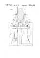
- FIG. 1is a schematic sketch of a vertical partial cross-section through an example of the mandrel, forming rollers and means for operating said rollers of a machine according to the invention, with a sheet to be formed in position ready to be formed.
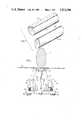
- FIG. 2is a perspective view of two tubes which can be formed by the invention by using mandrels of different cross-sections.
- FIG. 3is a side view of the apparatus as shown in FIG. 1, the sheet omitted for ease of illustration.
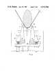
- FIG. 4is a sketch similar to FIG. 1 illustrated at an intermediate stage of the first forming operation.
- FIG. 5is a sketch similar to that of FIG. 4 but illustrated at a stage of the first forming operation which may suitably be the end of the first forming operation.
- FIGS. 6 and 7are sketches showing means for finishing and completing the forming operation and seaming the formed tube.
- FIG. 8shows two sheets positioned for forming.
- FIG. 9shows track for the finishing means.
- a pair of roller means 10mounted to be operable to roll against the surface of a sheet 11 to form it over the surface of a mandrel 12.
- a final forming operationis carried out to close the sheet 11 over the mandrel and form a seal 13 at the joint.
- the resulting tube 14 with the seal 13can be seen from FIG. 2, the shape of the cross-section of the tube 14 can be selected by appropriate choice of the shape of the mandrel 12.
- the final forming operationmay be carried out by any suitable technique.
- each roller means 10 supported on corresponding symmetrical pairs of arm meansare arranged to move symmetrically over the surface of the mandrel from the position shown in FIG. 1 through the position shown in FIG. 4 to at least the position shown in FIG. 5.
- Each of the roller means 10extends along an axis parallel to mandrel 12 and over the length thereof. Since the length of the mandrel may be considerable say, for example, 60 inches, each roller means 10 of the pair are, in the illustrated embodiment subdivided into rollers 15, 16 axially aligned with each other and supported on separate supporting and operating arms 17, 18 respectively.
- each roller 10is a member of a symmetrical pair of rollers 15 and each arm 17 is a member of a symmetrical pair of arms 17.
- Each roller 15, 16comprises a plurality of rolling elements 19.
- the supporting and operating arms 17, 18 for rollers 15, 16 shown laterally adjacent one another in FIG. 3are each symmetrically arranged with their counterparts for the other roller means 10 comprising rollers 15, 16 and rolling elements 19.
- the symmetrical arms 17are pivotally mounted at symmetrical pivots 20 on a platform 21 beneath the mandrel 12.
- the symmetrical arms 18are similarly mounted on pivots 25 and any description hereinafter with respect to arms 17 applies similarly to arms 18 and, in fact, to further pairs of symmetrical arms carrying rollers should they be provided.
- Platform 21is movably located below the mandrel 12 and pivots 20 are located thereon such that when the machine is in its ready position (FIG.
- a torsion bar 44is provided extending over the length of the mandrel 12 beneath the platform 21.
- the bar 44is rotatably set in fixed bearings 45 near its ends and at its ends carries pinion wheels 46.
- the wheels 46mesh with vertical racks 47 depending from the platform 21 and of sufficient length to continue to mesh with pinion wheels 46 even when platform 21 is at its highest point.
- biasing means 23for the symmetrical arms 17 and hence for the roller 15 which biasing means 23 is automatically self-adjusting to the appropriate forming force according to the position of the roller means 10 with respect to the surface of the mandrel 12.
- Similar biasing means 24is provided for symmetrical arms 18 and further similar biasing means is provided for any further pairs of arms.
- the biasing means 23comprise, for each of the symmetrical arms 17 a block 26 fixed to the arm and provided with a vertically directed force between a fixed point or points on the platform 21 and the block.
- the block as illustratedis of U-shape comprising a web in the form of a plate 27 arranged, in the ready position parallel to the platform 21.
- the legs 28 of the U-shaped block 26are blocks in the form of right-angled triangles, one perpendicular side of which extends across plate 27 either fixed thereto or integral therewith.
- the other perpendicular side of each triangular blockis fixed to a vertical portion 29 of each arm 17, for example, by bolts 31.
- the undersurface of the plate 27has a thickened portion or rib 32 running its length, which rib 32 bears, in the present embodiment, against compression springs 33.
- compression springs 33may easily be replaced by hydraulic or pneumatic or other means to exert expansive force between plate 27 and platform 21.
- the springs 33are fixed to the platform 21 at one end and bear vertically at the other end, when the machine is in the ready position, against rib 32 of plate 27.
- no forming forceis required and the springs 33 may only be under light compression to hold their position. Arrangements of the springs can be contemplated where no compression is required in this position. It is important that the forces provided for each of the symmetrical arms 17 are similar and that the forces provided by similar biasing means 24 are again similar.
- the sheet 11is held in position in the ready position by elongated support 22 which extends along the length of the mandrel 12 and which is under hydraulic or pneumatic pressure through hydraulic jacks 34 to hold the sheet 11 against mandrel 12 Jacks 34 are fixed to platform 21 and extend through hole 35 in a lower platform.
- Mandrel 12is interchangeable for other mandrels having different arcuate sections. Moreover, although fixed in position for having sheet 11 formed thereon, it is hingably mounted to be swingable in a horizontal plane to lie at, say, right angles to the axes of the roller means 10 for removal and changing. Thus, mandrel 12 is suitably fixed to a hinge member 36 which is pivoted at pivot pin 37. During forming, the mandrel is fixed in position by hydraulically operated support ram 38.
- a mandrel 12 of chosen arcuate sectionis selected and fixed in position on hinge member 36 by hydraulic support ram 38.
- Sheet 11is fed to lie on support 22, which is then adjusted by hydraulic or pneumatic operation of jacks 34 to hold the sheet securely between the mandrel 12 and support 22.
- the platform 21is moved upwardly so that the pair of roller means 10 bear against the underside of sheet 11 thereby to bend it about mandrel 12.
- the pair of roller means 10are pushed apart to follow the form of the sheet 11 as it bends over the mandrel 12 and the symmetrical arms 17, and the arms 18, open like jaws as they hinge on pivots 20, or 25.
- Carriage 41carries seaming rollers which bend sequentially the pulled together edges of sheet 11 to form seams 13 of FIG. 2.
- the equipmentmay be used to form any type of formable sheet, the springs 33 or their mechanical equivalent parts being chosen to have a strength suitable for the forming force necessary to the type of sheet to be formed.
- the speed of lifting the platform and the hydraulic power needed for lifting sameis also a matter of choice according to the formability of the sheet 11.
Landscapes
- Engineering & Computer Science (AREA)
- Mechanical Engineering (AREA)
- Bending Of Plates, Rods, And Pipes (AREA)
- Shaping Of Tube Ends By Bending Or Straightening (AREA)
Abstract
Description
Claims (2)
Applications Claiming Priority (2)
| Application Number | Priority Date | Filing Date | Title |
|---|---|---|---|
| CA000337214ACA1119469A (en) | 1979-10-09 | 1979-10-09 | Apparatus and method for forming seamed tube |
| CA337214 | 1979-10-09 |
Related Parent Applications (1)
| Application Number | Title | Priority Date | Filing Date |
|---|---|---|---|
| US06318789Continuation | 1981-11-06 |
Publications (1)
| Publication Number | Publication Date |
|---|---|
| US4513596Atrue US4513596A (en) | 1985-04-30 |
Family
ID=4115309
Family Applications (1)
| Application Number | Title | Priority Date | Filing Date |
|---|---|---|---|
| US06/462,868Expired - LifetimeUS4513596A (en) | 1979-10-09 | 1983-02-01 | Apparatus and method for forming seamed tube |
Country Status (6)
| Country | Link |
|---|---|
| US (1) | US4513596A (en) |
| JP (1) | JPS56131014A (en) |
| CA (1) | CA1119469A (en) |
| DE (1) | DE2948115A1 (en) |
| FR (1) | FR2467027B1 (en) |
| GB (1) | GB2040746B (en) |
Cited By (29)
| Publication number | Priority date | Publication date | Assignee | Title |
|---|---|---|---|---|
| US4682488A (en)* | 1985-01-10 | 1987-07-28 | Carrier Corporation | Apparatus for forming slit fin coils |
| US4911209A (en)* | 1989-03-15 | 1990-03-27 | Expo Wire Company | Method and apparatus for forming wire mesh cages |
| US5159747A (en)* | 1987-02-10 | 1992-11-03 | Fuji Photo Film Co., Ltd. | Film cartridge producing method |
| US5309627A (en)* | 1990-12-28 | 1994-05-10 | Cooper Power Systems, Inc. | Apparatus for making a transformer core of non-circular cross-section |
| US5906759A (en)* | 1996-12-26 | 1999-05-25 | Medinol Ltd. | Stent forming apparatus with stent deforming blades |
| US5943891A (en)* | 1996-11-28 | 1999-08-31 | Sango Co., Ltd. | Silencer shell forming apparatus |
| US6000115A (en)* | 1996-11-28 | 1999-12-14 | Sango Co., Ltd | Shell lock seaming machine |
| US6405827B1 (en) | 2000-05-10 | 2002-06-18 | Tenneco Automotive Operating Company Inc. | Lock seam for canisters |
| US6446322B1 (en) | 2000-05-10 | 2002-09-10 | Tenneco Automotive Operating Company Inc. | Method and apparatus for sealing canisters |
| US6651338B2 (en)* | 2000-10-05 | 2003-11-25 | Hueck Folien Gmbh & Co. Kg | Method for the production of a cylindrical embossing sheet |
| KR20040009380A (en)* | 2002-07-23 | 2004-01-31 | (주)신흥산업 | metal plate round-curving method and device |
| US20050142044A1 (en)* | 2003-12-26 | 2005-06-30 | Calsonic Kansei Corporation | Assembly device of support mat for ceramic catalyst carrier |
| US20050147708A1 (en)* | 2004-01-05 | 2005-07-07 | Calsonic Kansei Corporation | Assembly device of support mat for ceramic catalyst carrier |
| US20060016063A1 (en)* | 2004-07-26 | 2006-01-26 | Gharib Mohamed T | Lockseaming process and apparatus for the same |
| US20070059075A1 (en)* | 2002-03-15 | 2007-03-15 | Fuji Photo Film Co. Ltd. | Apparatus for manufacturing film cartridge and for feeding plate material |
| US20070077347A1 (en)* | 1996-12-26 | 2007-04-05 | Jacob Richter | Flat process of drug coating for stents |
| US20090019908A1 (en)* | 2006-04-04 | 2009-01-22 | Brueninghaus Hydromatik Gmbh | Method and bending device for bending a sheet metal part |
| US7669448B1 (en) | 2005-07-20 | 2010-03-02 | Mohamed Gharib | Lockseaming process and apparatus for same |
| US20110238152A1 (en)* | 2006-03-15 | 2011-09-29 | Medinol Ltd. | Flat process of preparing drug eluting stents |
| US20160053664A1 (en)* | 2013-04-10 | 2016-02-25 | Toyota Jidosha Kabushiki Kaisha | Muffler and its corresponding manufacturing method |
| CN106077182A (en)* | 2016-05-06 | 2016-11-09 | 江苏金泽重型机械有限公司 | A kind of tuber |
| CN106181406A (en)* | 2016-08-19 | 2016-12-07 | 零八电子集团四川天源机械有限公司 | Lamp holder high frequency circle device for automatically molding |
| CN111729948A (en)* | 2020-07-21 | 2020-10-02 | 江苏宏宝优特管业制造有限公司 | A square steel pipe forming device |
| CN112642896A (en)* | 2020-08-11 | 2021-04-13 | 陕西建工机械施工集团有限公司 | Arc bending method of steel rail for sliding |
| CN112916689A (en)* | 2021-01-25 | 2021-06-08 | 赵海勇 | Bone fracture plate forming machine for bone fracture materials in orthopedic surgery |
| US11110508B2 (en)* | 2018-07-13 | 2021-09-07 | David G. Stolp | Automatic precision clinching system for manufacturing sheet metal tubes |
| US20230002020A1 (en)* | 2021-06-30 | 2023-01-05 | FabX Industries, Inc. | Automated Method for Nose Cone Manufacturing |
| RU2802880C1 (en)* | 2022-12-12 | 2023-09-05 | Федеральное государственное автономное образовательное учреждение высшего образования "Сибирский федеральный университет" | Stamp for making cylinder courses flexible |
| CN118385400A (en)* | 2024-06-26 | 2024-07-26 | 江苏润杨精密制造有限公司 | Auto-parts equipment of bending |
Families Citing this family (32)
| Publication number | Priority date | Publication date | Assignee | Title |
|---|---|---|---|---|
| DE3637985C2 (en)* | 1986-11-07 | 1994-05-19 | Siemens Ag | Bending punch |
| DE4029723A1 (en)* | 1990-09-20 | 1992-03-26 | Rheinzink Gmbh | METHOD AND DEVICE FOR THE PRODUCTION OF HANGER GUTTERS |
| DE29511896U1 (en)* | 1995-07-24 | 1995-10-05 | Vogl, Erich R., 91448 Emskirchen | Device for hanging a metal rail in the form of a so-called C-profile |
| RU2231410C1 (en)* | 2003-01-21 | 2004-06-27 | Общество с ограниченной ответственностью "АМИРА-Стальконструкция" | Method for making elongated shapes |
| RU2236320C1 (en)* | 2003-01-21 | 2004-09-20 | Общество с ограниченной ответственностью "АМИРА-Стальконструкция" | Apparatus for making elongated sections |
| US7775966B2 (en) | 2005-02-24 | 2010-08-17 | Ethicon Endo-Surgery, Inc. | Non-invasive pressure measurement in a fluid adjustable restrictive device |
| US8016744B2 (en) | 2005-02-24 | 2011-09-13 | Ethicon Endo-Surgery, Inc. | External pressure-based gastric band adjustment system and method |
| US7775215B2 (en) | 2005-02-24 | 2010-08-17 | Ethicon Endo-Surgery, Inc. | System and method for determining implanted device positioning and obtaining pressure data |
| US7699770B2 (en) | 2005-02-24 | 2010-04-20 | Ethicon Endo-Surgery, Inc. | Device for non-invasive measurement of fluid pressure in an adjustable restriction device |
| US7927270B2 (en) | 2005-02-24 | 2011-04-19 | Ethicon Endo-Surgery, Inc. | External mechanical pressure sensor for gastric band pressure measurements |
| US8066629B2 (en) | 2005-02-24 | 2011-11-29 | Ethicon Endo-Surgery, Inc. | Apparatus for adjustment and sensing of gastric band pressure |
| US7658196B2 (en) | 2005-02-24 | 2010-02-09 | Ethicon Endo-Surgery, Inc. | System and method for determining implanted device orientation |
| US8870742B2 (en) | 2006-04-06 | 2014-10-28 | Ethicon Endo-Surgery, Inc. | GUI for an implantable restriction device and a data logger |
| US8152710B2 (en) | 2006-04-06 | 2012-04-10 | Ethicon Endo-Surgery, Inc. | Physiological parameter analysis for an implantable restriction device and a data logger |
| US8187163B2 (en) | 2007-12-10 | 2012-05-29 | Ethicon Endo-Surgery, Inc. | Methods for implanting a gastric restriction device |
| US8100870B2 (en) | 2007-12-14 | 2012-01-24 | Ethicon Endo-Surgery, Inc. | Adjustable height gastric restriction devices and methods |
| US8142452B2 (en) | 2007-12-27 | 2012-03-27 | Ethicon Endo-Surgery, Inc. | Controlling pressure in adjustable restriction devices |
| US8377079B2 (en) | 2007-12-27 | 2013-02-19 | Ethicon Endo-Surgery, Inc. | Constant force mechanisms for regulating restriction devices |
| US8591395B2 (en) | 2008-01-28 | 2013-11-26 | Ethicon Endo-Surgery, Inc. | Gastric restriction device data handling devices and methods |
| US8192350B2 (en) | 2008-01-28 | 2012-06-05 | Ethicon Endo-Surgery, Inc. | Methods and devices for measuring impedance in a gastric restriction system |
| US8337389B2 (en) | 2008-01-28 | 2012-12-25 | Ethicon Endo-Surgery, Inc. | Methods and devices for diagnosing performance of a gastric restriction system |
| US7844342B2 (en) | 2008-02-07 | 2010-11-30 | Ethicon Endo-Surgery, Inc. | Powering implantable restriction systems using light |
| US8221439B2 (en) | 2008-02-07 | 2012-07-17 | Ethicon Endo-Surgery, Inc. | Powering implantable restriction systems using kinetic motion |
| US8114345B2 (en) | 2008-02-08 | 2012-02-14 | Ethicon Endo-Surgery, Inc. | System and method of sterilizing an implantable medical device |
| US8057492B2 (en) | 2008-02-12 | 2011-11-15 | Ethicon Endo-Surgery, Inc. | Automatically adjusting band system with MEMS pump |
| US8591532B2 (en) | 2008-02-12 | 2013-11-26 | Ethicon Endo-Sugery, Inc. | Automatically adjusting band system |
| US8034065B2 (en) | 2008-02-26 | 2011-10-11 | Ethicon Endo-Surgery, Inc. | Controlling pressure in adjustable restriction devices |
| US8187162B2 (en) | 2008-03-06 | 2012-05-29 | Ethicon Endo-Surgery, Inc. | Reorientation port |
| US8233995B2 (en) | 2008-03-06 | 2012-07-31 | Ethicon Endo-Surgery, Inc. | System and method of aligning an implantable antenna |
| EP2529849B1 (en)* | 2011-05-31 | 2021-03-10 | SMS group GmbH | Device and method for manufacturing slot pipes made of sheet panels |
| CN108655219B (en)* | 2018-05-03 | 2020-08-14 | 蓬莱大金海洋重工有限公司 | Plate material rolling process |
| CN115846471B (en)* | 2023-02-20 | 2023-05-02 | 江苏世烨鼎电子科技有限公司 | Three-stage linkage bending machine |
Citations (4)
| Publication number | Priority date | Publication date | Assignee | Title |
|---|---|---|---|---|
| US1200190A (en)* | 1913-10-15 | 1916-10-03 | Paul R Hahnemann | Can-body-forming machine. |
| SU452393A1 (en)* | 1972-05-04 | 1974-12-05 | Предприятие П/Я Р-6205 | Bending device |
| US4141235A (en)* | 1976-09-18 | 1979-02-27 | Masamitsu Ishihara | Hydraulic bending machine |
| GB1550629A (en)* | 1976-11-25 | 1979-08-15 | Steel Precision Eng Ltd | Making metal tubes |
Family Cites Families (7)
| Publication number | Priority date | Publication date | Assignee | Title |
|---|---|---|---|---|
| GB558378A (en)* | 1942-11-13 | 1944-01-03 | Tate Of Leeds Ltd | Improvements in and relating to sheet metal working machines |
| US2703062A (en)* | 1950-10-06 | 1955-03-01 | Oldberg Mfg Company | Apparatus for forming tubes |
| GB795166A (en)* | 1955-09-29 | 1958-05-21 | Westinghouse Electric Int Co | Improvements in or relating to the fabrication of hollow airfoil blades |
| US3074461A (en)* | 1960-05-23 | 1963-01-22 | Westinghouse Electric Corp | Roll forming systems |
| FR1293739A (en)* | 1961-05-23 | 1962-05-18 | Westinghouse Electric Corp | Bending system |
| US3802239A (en)* | 1972-06-08 | 1974-04-09 | Valmont Industries | Machine and method for forming tapered tubes |
| JPS6044050B2 (en)* | 1976-09-10 | 1985-10-01 | 新日本製鐵株式会社 | Multi-stage forming method for long shells |
- 1979
- 1979-10-09CACA000337214Apatent/CA1119469A/ennot_activeExpired
- 1979-11-08GBGB7938734Apatent/GB2040746B/ennot_activeExpired
- 1979-11-29DEDE19792948115patent/DE2948115A1/ennot_activeCeased
- 1979-12-07JPJP15820179Apatent/JPS56131014A/enactiveGranted
- 1979-12-14FRFR7930705Apatent/FR2467027B1/ennot_activeExpired
- 1983
- 1983-02-01USUS06/462,868patent/US4513596A/ennot_activeExpired - Lifetime
Patent Citations (4)
| Publication number | Priority date | Publication date | Assignee | Title |
|---|---|---|---|---|
| US1200190A (en)* | 1913-10-15 | 1916-10-03 | Paul R Hahnemann | Can-body-forming machine. |
| SU452393A1 (en)* | 1972-05-04 | 1974-12-05 | Предприятие П/Я Р-6205 | Bending device |
| US4141235A (en)* | 1976-09-18 | 1979-02-27 | Masamitsu Ishihara | Hydraulic bending machine |
| GB1550629A (en)* | 1976-11-25 | 1979-08-15 | Steel Precision Eng Ltd | Making metal tubes |
Cited By (46)
| Publication number | Priority date | Publication date | Assignee | Title |
|---|---|---|---|---|
| US4682488A (en)* | 1985-01-10 | 1987-07-28 | Carrier Corporation | Apparatus for forming slit fin coils |
| US5172470A (en)* | 1987-02-01 | 1992-12-22 | Fuji Photo Film Co., Ltd. | Method of and apparatus for shaping film cartridge |
| US5159747A (en)* | 1987-02-10 | 1992-11-03 | Fuji Photo Film Co., Ltd. | Film cartridge producing method |
| US4911209A (en)* | 1989-03-15 | 1990-03-27 | Expo Wire Company | Method and apparatus for forming wire mesh cages |
| US5309627A (en)* | 1990-12-28 | 1994-05-10 | Cooper Power Systems, Inc. | Apparatus for making a transformer core of non-circular cross-section |
| US6000115A (en)* | 1996-11-28 | 1999-12-14 | Sango Co., Ltd | Shell lock seaming machine |
| US5943891A (en)* | 1996-11-28 | 1999-08-31 | Sango Co., Ltd. | Silencer shell forming apparatus |
| US6197048B1 (en) | 1996-12-26 | 2001-03-06 | Medinol Ltd. | Stent |
| EP0853927A3 (en)* | 1996-12-26 | 2003-04-02 | Medinol Ltd. | Stent fabrication method and apparatus |
| US6114049A (en)* | 1996-12-26 | 2000-09-05 | Medinol Ltd. | Stent fabrication method |
| US5906759A (en)* | 1996-12-26 | 1999-05-25 | Medinol Ltd. | Stent forming apparatus with stent deforming blades |
| US6299755B1 (en) | 1996-12-26 | 2001-10-09 | Medinol Ltd. | Stent fabrication method and apparatus |
| US20070077347A1 (en)* | 1996-12-26 | 2007-04-05 | Jacob Richter | Flat process of drug coating for stents |
| US7208009B2 (en) | 1996-12-26 | 2007-04-24 | Medinol, Ltd. | Stent fabrication method |
| US5997703A (en)* | 1996-12-26 | 1999-12-07 | Medinol Ltd. | Stent fabrication method |
| US20040162605A1 (en)* | 1996-12-26 | 2004-08-19 | Jacob Richter | Stent fabrication method |
| US7959664B2 (en) | 1996-12-26 | 2011-06-14 | Medinol, Ltd. | Flat process of drug coating for stents |
| US6692522B1 (en) | 1996-12-26 | 2004-02-17 | Medinol, Ltd | Stent having lumen comprising welded engagement points and method of fabricating same |
| US6446322B1 (en) | 2000-05-10 | 2002-09-10 | Tenneco Automotive Operating Company Inc. | Method and apparatus for sealing canisters |
| US6405827B1 (en) | 2000-05-10 | 2002-06-18 | Tenneco Automotive Operating Company Inc. | Lock seam for canisters |
| US6651338B2 (en)* | 2000-10-05 | 2003-11-25 | Hueck Folien Gmbh & Co. Kg | Method for the production of a cylindrical embossing sheet |
| US20070059075A1 (en)* | 2002-03-15 | 2007-03-15 | Fuji Photo Film Co. Ltd. | Apparatus for manufacturing film cartridge and for feeding plate material |
| KR20040009380A (en)* | 2002-07-23 | 2004-01-31 | (주)신흥산업 | metal plate round-curving method and device |
| US20050142044A1 (en)* | 2003-12-26 | 2005-06-30 | Calsonic Kansei Corporation | Assembly device of support mat for ceramic catalyst carrier |
| US7441333B2 (en)* | 2003-12-26 | 2008-10-28 | Calsonic Kansei Corporation | Assembly device of support mat for ceramic catalyst carrier |
| US20050147708A1 (en)* | 2004-01-05 | 2005-07-07 | Calsonic Kansei Corporation | Assembly device of support mat for ceramic catalyst carrier |
| US7320176B2 (en)* | 2004-01-05 | 2008-01-22 | Calsonic Kansei Corporation | Assembly device of support mat for ceramic catalyst carrier |
| US20060016063A1 (en)* | 2004-07-26 | 2006-01-26 | Gharib Mohamed T | Lockseaming process and apparatus for the same |
| US7669448B1 (en) | 2005-07-20 | 2010-03-02 | Mohamed Gharib | Lockseaming process and apparatus for same |
| US20110238152A1 (en)* | 2006-03-15 | 2011-09-29 | Medinol Ltd. | Flat process of preparing drug eluting stents |
| US8828077B2 (en) | 2006-03-15 | 2014-09-09 | Medinol Ltd. | Flat process of preparing drug eluting stents |
| US20090019908A1 (en)* | 2006-04-04 | 2009-01-22 | Brueninghaus Hydromatik Gmbh | Method and bending device for bending a sheet metal part |
| US9719404B2 (en)* | 2013-04-10 | 2017-08-01 | Toyota Jidosha Kabushiki Kaisha | Muffler and its corresponding manufacturing method |
| US20160053664A1 (en)* | 2013-04-10 | 2016-02-25 | Toyota Jidosha Kabushiki Kaisha | Muffler and its corresponding manufacturing method |
| CN106077182A (en)* | 2016-05-06 | 2016-11-09 | 江苏金泽重型机械有限公司 | A kind of tuber |
| CN106181406A (en)* | 2016-08-19 | 2016-12-07 | 零八电子集团四川天源机械有限公司 | Lamp holder high frequency circle device for automatically molding |
| CN106181406B (en)* | 2016-08-19 | 2018-05-11 | 零八一电子集团四川天源机械有限公司 | Lamp cap high-frequency ring device for automatically molding |
| US11110508B2 (en)* | 2018-07-13 | 2021-09-07 | David G. Stolp | Automatic precision clinching system for manufacturing sheet metal tubes |
| CN111729948A (en)* | 2020-07-21 | 2020-10-02 | 江苏宏宝优特管业制造有限公司 | A square steel pipe forming device |
| CN112642896A (en)* | 2020-08-11 | 2021-04-13 | 陕西建工机械施工集团有限公司 | Arc bending method of steel rail for sliding |
| CN112916689A (en)* | 2021-01-25 | 2021-06-08 | 赵海勇 | Bone fracture plate forming machine for bone fracture materials in orthopedic surgery |
| CN112916689B (en)* | 2021-01-25 | 2023-10-13 | 赵海勇 | Bone fracture plate forming machine for bone fracture in bone surgery |
| US20230002020A1 (en)* | 2021-06-30 | 2023-01-05 | FabX Industries, Inc. | Automated Method for Nose Cone Manufacturing |
| US11767087B2 (en)* | 2021-06-30 | 2023-09-26 | FabX Industries, Inc. | Automated method for nose cone manufacturing |
| RU2802880C1 (en)* | 2022-12-12 | 2023-09-05 | Федеральное государственное автономное образовательное учреждение высшего образования "Сибирский федеральный университет" | Stamp for making cylinder courses flexible |
| CN118385400A (en)* | 2024-06-26 | 2024-07-26 | 江苏润杨精密制造有限公司 | Auto-parts equipment of bending |
Also Published As
| Publication number | Publication date |
|---|---|
| FR2467027B1 (en) | 1985-10-04 |
| JPS56131014A (en) | 1981-10-14 |
| JPS6356010B2 (en) | 1988-11-07 |
| DE2948115A1 (en) | 1981-04-23 |
| GB2040746B (en) | 1983-03-23 |
| FR2467027A1 (en) | 1981-04-17 |
| CA1119469A (en) | 1982-03-09 |
| GB2040746A (en) | 1980-09-03 |
Similar Documents
| Publication | Publication Date | Title |
|---|---|---|
| US4513596A (en) | Apparatus and method for forming seamed tube | |
| US4706488A (en) | Method of roll forming cylindrical pipe | |
| CA1119849A (en) | Line pipe forming apparatus and method | |
| US4468946A (en) | Method of making lambda beams | |
| US5115658A (en) | Shaping machine for cylindrically bending a plate | |
| KR101555968B1 (en) | Bending machine for pipe | |
| US2280564A (en) | Uncoiling device | |
| US4339938A (en) | Method and apparatus for forming metal pipes and tubes | |
| US4606208A (en) | Pipe forming apparatus | |
| US4628721A (en) | Method of roll forming cylindrical pipe | |
| US3832879A (en) | Bending machines | |
| US5622075A (en) | Bending machine | |
| CA1134650A (en) | Up-set shrinker for producing thick wall steel pipe | |
| US4449388A (en) | Method of bending shaped metal sheet and apparatus for carrying out the method | |
| US2799317A (en) | Resilient wheel apparatus and method for forming strip material | |
| US5720195A (en) | Lower forming roll removal and replacement structure | |
| US4930329A (en) | Installation for producing metal girders | |
| JPH03268822A (en) | Method and device for manufacturing liner plate | |
| US1968455A (en) | Method and apparatus for forming pipe | |
| CN114570784B (en) | Forming device of large-diameter stainless steel pipe | |
| US3373586A (en) | Helical seam pipe making machine | |
| US1899143A (en) | Tube manufacture | |
| US5647241A (en) | Rotary upper roll selector | |
| US6427513B2 (en) | Process and device for producing pipes as per the UOE process | |
| JP3415007B2 (en) | Apron device on the entry and exit side of the junction bogie |
Legal Events
| Date | Code | Title | Description |
|---|---|---|---|
| AS | Assignment | Owner name:EAGLE PRECISION TOOL LTD., PO BOX 786, 565 WEST ST Free format text:ASSIGNMENT OF ASSIGNORS INTEREST.;ASSIGNOR:USHER, GEORGE R.;REEL/FRAME:004361/0156 Effective date:19850108 | |
| STCF | Information on status: patent grant | Free format text:PATENTED CASE | |
| FEPP | Fee payment procedure | Free format text:PAT HOLDER CLAIMS SMALL ENTITY STATUS - SMALL BUSINESS (ORIGINAL EVENT CODE: SM02); ENTITY STATUS OF PATENT OWNER: LARGE ENTITY Free format text:PAYOR NUMBER ASSIGNED (ORIGINAL EVENT CODE: ASPN); ENTITY STATUS OF PATENT OWNER: LARGE ENTITY | |
| FPAY | Fee payment | Year of fee payment:4 | |
| FPAY | Fee payment | Year of fee payment:8 | |
| FEPP | Fee payment procedure | Free format text:PAT HLDR NO LONGER CLAIMS SMALL ENT STAT AS SMALL BUSINESS (ORIGINAL EVENT CODE: LSM2); ENTITY STATUS OF PATENT OWNER: LARGE ENTITY Free format text:PAYER NUMBER DE-ASSIGNED (ORIGINAL EVENT CODE: RMPN); ENTITY STATUS OF PATENT OWNER: LARGE ENTITY Free format text:PAYOR NUMBER ASSIGNED (ORIGINAL EVENT CODE: ASPN); ENTITY STATUS OF PATENT OWNER: LARGE ENTITY | |
| FEPP | Fee payment procedure | Free format text:PAYER NUMBER DE-ASSIGNED (ORIGINAL EVENT CODE: RMPN); ENTITY STATUS OF PATENT OWNER: LARGE ENTITY Free format text:PAYOR NUMBER ASSIGNED (ORIGINAL EVENT CODE: ASPN); ENTITY STATUS OF PATENT OWNER: LARGE ENTITY | |
| FPAY | Fee payment | Year of fee payment:12 | |
| AS | Assignment | Owner name:CANADIAN IMPERIAL BANK OF COMMERCE, CANADA Free format text:SECURITY AGREEMENT;ASSIGNOR:EAGLE PRECISION TECHNOLOGIES INC.;REEL/FRAME:017411/0182 Effective date:19991026 | |
| AS | Assignment | Owner name:EAGLE PRECISION TECHNOLOGIES INC., CANADA Free format text:STATEMENT OF RELEASE OF SECURITY AGREEMENT OVER INTELLECTUAL PROPERTY;ASSIGNOR:CANADIAN IMPERIAL BANK OF COMMERCE;REEL/FRAME:018375/0431 Effective date:20060411 | |
| AS | Assignment | Owner name:EAGLE PRECISION TECHNOLOGIES LTD., CANADA Free format text:ASSIGNMENT OF ASSIGNORS INTEREST;ASSIGNOR:EAGLE PRECISION TECHNOLOGIES INC.;REEL/FRAME:018597/0177 Effective date:20060410 | |
| AS | Assignment | Owner name:ROYAL BANK OF CANADA, CANADA Free format text:SECURITY INTERESTS AND LIENS;ASSIGNOR:EAGLE PRECISION TECHNOLOGIES LTD.;REEL/FRAME:022331/0861 Effective date:20070725 | |
| AS | Assignment | Owner name:ADDISONMCKEE CANADA ULC, OHIO Free format text:ASSIGNMENT OF ASSIGNORS INTEREST;ASSIGNOR:EAGLE PRECISION TECHNOLOGIES LTD.;REEL/FRAME:022668/0806 Effective date:20090318 Owner name:ADDISONMCKEE INC., OHIO Free format text:ASSIGNMENT OF ASSIGNORS INTEREST;ASSIGNOR:ADDISONMCKEE CANADA ULC;REEL/FRAME:022668/0825 Effective date:20090506 |