US4511979A - Programmable time registering AC electric energy meter having randomized load control - Google Patents
Programmable time registering AC electric energy meter having randomized load controlDownload PDFInfo
- Publication number
- US4511979A US4511979AUS06/411,220US41122082AUS4511979AUS 4511979 AUS4511979 AUS 4511979AUS 41122082 AUS41122082 AUS 41122082AUS 4511979 AUS4511979 AUS 4511979A
- Authority
- US
- United States
- Prior art keywords
- load
- rate change
- change control
- time
- data code
- Prior art date
- Legal status (The legal status is an assumption and is not a legal conclusion. Google has not performed a legal analysis and makes no representation as to the accuracy of the status listed.)
- Expired - Fee Related
Links
Images


Classifications
- G—PHYSICS
- G01—MEASURING; TESTING
- G01R—MEASURING ELECTRIC VARIABLES; MEASURING MAGNETIC VARIABLES
- G01R21/00—Arrangements for measuring electric power or power factor
- G01R21/007—Adapted for special tariff measuring
- G—PHYSICS
- G01—MEASURING; TESTING
- G01R—MEASURING ELECTRIC VARIABLES; MEASURING MAGNETIC VARIABLES
- G01R21/00—Arrangements for measuring electric power or power factor
- G—PHYSICS
- G06—COMPUTING OR CALCULATING; COUNTING
- G06Q—INFORMATION AND COMMUNICATION TECHNOLOGY [ICT] SPECIALLY ADAPTED FOR ADMINISTRATIVE, COMMERCIAL, FINANCIAL, MANAGERIAL OR SUPERVISORY PURPOSES; SYSTEMS OR METHODS SPECIALLY ADAPTED FOR ADMINISTRATIVE, COMMERCIAL, FINANCIAL, MANAGERIAL OR SUPERVISORY PURPOSES, NOT OTHERWISE PROVIDED FOR
- G06Q50/00—Information and communication technology [ICT] specially adapted for implementation of business processes of specific business sectors, e.g. utilities or tourism
- G06Q50/06—Energy or water supply
Definitions
- This inventionrelates, in general, to programmable time-registering meters for measuring AC electric energy consumption during time differentiated billing rate periods and for controlling a load. More specifically, this invention randomizes the timing of load shedding and reconnecting.
- Electric energy billing meters of the electromechanical typeare commonly used to measure the amount of electrical energy consumed at the premises of electric energy users.
- the electric energy supplierbills each user on the basis of the quantity of electric energy consumed during the billing period.
- Most billing meters in use todaymeasure the total consumption of electric energy (kilowatt-hours) or a maximum peak demand (kilowatt demand) during a given time interval, usually a month. It is often desired to provide an electric energy meter for measuring both kilowatt-hour consumption and kilowatt demand and for separately totalizing these parameters as they are measured during different designated time intervals of each day. This method of metering is known as time-of-day or time-registering metering by those skilled in the art.
- the time-of-day intervalstypically three, generally reflect those times of the day when electric energy demand is at its highest, intermediate, or lowest level.
- the billing rates corresponding to these time intervalsare usually designated as the on-peak rate, the mid-peak rate, and the base rate, respectively.
- Induction watthour metersequipped with mechanical kilowatt-hour registers for measuring consumption during various time intervals of each day are known in the prior art. Selective operation of these registers is provided in response to mechanical time switch mechanisms.
- these mechanical registers and time mechanismshave limited measuring and accumulating capabilities with respect to daily time intervals and variations of these intervals between week days and weekend days.
- the recent application of solid-state electronic devices to time-registering metershas eliminated the need for mechanical registers and permitted an increase in the number of electrical energy parameters that can be measured. The result has been an increase in the number of rate selection schedules avilable to the utility and greater flexibility in their assignement.
- One common randomized load control methodemploys a resistor-capacitor timing circuit.
- a capacitorcharges through a resistor, and a subsequent shed command causes the load to be shed for a time determined by the voltage across the capacitor.
- Variations in the values of the resistor and capacitorcause the loads to be reconnected to the system at varying times.
- use of RC timing circuitscauses clusters of loads to be reconnected to the system within a very short interval. The result is a high differential power demand placed on the electrical energy system.
- U.S. Pat. No. 4,213,058discloses a technique for randomly reconnecting the load to an electrical energy system.
- a central controllertransmits a load shed command to various load management terminals.
- a load management terminalUpon receipt of the shed command, a load management terminal generates a reset pulse which sheds the load associated with that load management terminal and resets a binary counter. Resetting the binary counter enables the counter to then begin counting asynchronous clock pulses which are being continuously generated within the load management terminal; the clock signal has a period T.
- the positive going transition of the second clock pulse received by the binary counter after it has been resetinhibits receipt of further clock pulses and causes the load to be reconnected to the power system.
- the randomness associated with this timing cirucitis due to the uncertainty of whether the reset pulse will be received during a clock pulse or during the space between clock pulses. If the reset pulse should occur immediately before the positive going transition of a clock pulse, the load will be disconnected from the system for a time equal to the period of the clock pulse signal, i.e. T. If the reset pulse occurs immediately after the negative going transition of a clock pulse, the load will be disconnected for a time equal to 2 ⁇ T.
- the present inventionis a time-registering electrical energy meter for connecting to a utility's power distribution system for measuring various parameters of electrical energy consumption during various time intervals of each day.
- the time-of-day meteralso provides load control based on load control data stored within its memory.
- the load control datacauses the load associated with the time-registering meter to be shed from the power system during preselected intervals of each day.
- this inventiondiscloses a novel means for randomizing load reconnections.
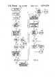
- FIG. 1is a block diagram of a time-registering AC electric energy meter constructed according to the teachings of the present invention
- FIG. 2is a flow chart illustrating the normal operating routine of the present invention.
- FIG. 3is a flow chart illustrating the time update and load control subroutine of the present invention.
- FIG. 1is a simplified block diagram of a programmable time-registering AC electric energy meter 10 constructed according to the teachings of the present invention.
- a pulse initiator 12produces a metering pulse signal 14 having a pulse repetition rate responsive to the magnitude of an AC electric energy quantity to be measured.
- the pulse initiatorproduces the metering pulse signal 14 in response to a line voltage V and a line current I which define the AC electric energy quantity to be measured.
- the metering pulse signal 14is input to a control logic circuit 16.
- the control logic circuit 16provides multi-function operations including accumulation of energy consumption data, communication with the outside world, and load control. Operation of the control logic circuit 16 is controlled by the software program in a fixed program read only memory (ROM) 18.
- ROMread only memory
- non-volatile random access memory 20including a total kilowatt-hour register 21.
- the random access memory 20stores, reads in, and writes out data related to electric energy consumption.
- a clock 22provides clock pulses to the control logic circuit 16. Under normal operations, clock pulses from the clock 22 are accumulated by the control logic circuit 16 and stored in the random access memory 20. This data is stored with a format of minutes, hours, day of the week, and day of the year. Also stored within separate registers of the random access memory 20 is the following consumption data: on-peak maximum demand, mid-peak maximum demand, base maximum demand, on-peak cumulative demand, mid-peak cumulative demand, base cumulative demand, total kilowatt hours, on-peak kilowatt hours, mid-peak kilowatt hours, and base kilowatt hours.
- the on-peak datarepresents consumption during those periods of each day when electrical energy demand is highest.
- the mid-peak and base datarepresent consumption during those periods of each day when electrical energy demand is at an intermediate and lowest level, respectively.
- the terms “off-peak " and "base”are synonymous and used interchangeably.
- One function of the control logic circuit 16is to determine to which of the aforementioned energy consumption data registers current energy consumption data is to be added. This determination is made on the basis of a plurality of rate change control points also stored within the random access memory 20. Each rate change control point defines a specific and predetermined minute, hour, day of the week, and day of the year. Each rate change control point also includes billing rate data (i.e. on-peak, mid-peak, or base) and load control data associated with the time interval defined by that rate change control point. In essence, the rate change control points divide the year into discrete time intervals and assign a billing rate period and load control operation to each interval.
- the control logic circuit 16compares the current time and date stored in the random access memory 20 with each rate change control point to determine into which time interval the current time and date fits.
- the rate change control point defining this time intervalbecomes the current rate change control point.
- the billing rate associated with the current rate change control pointdetermines whether the energy consumption data is to be accumulated in on-peak, mid-peak, or base registers of the random access memory 20.
- the time and date data and each of the time related energy consumption parametersare sequentially applied to a readout display 24 under control of the control logic circuit 16.
- the readout display 24 of the meter 10sequentially shows time in hours and minutes, the day of the week, and the day of the year. It also displays the following accumulated electric energy consumption parameters: total kilowatt hours, kilowatt hours for the on-peak, mid-peak, and base periods; and kilowatt demand for the on-peak, mid-peak, and base periods.
- An optical data link tube 26also communicates bidirectionally with control logic circuit 16. The optical data link tube 26 is disclosed in U.S. patent application No. 4,298,839 which issued to Johnston on Nov. 3, 1981.
- the optical data link tube 26communicates with an external programmer-reader unit 28 via a plurality of opto-electronic devices to initialize, reprogram, and read the time and consumption data stored in the random access memory 20 of the meter 10.
- the portable programmer reader unit 28is also utilized to perform various data verification and synchronization functions. Further information regarding the portable programmer reader unit 28 can be found in U.S. Pat. No. 4,291,375 which issued to Wolf on Sept. 22, 1981.
- a load control switch 30is responsive to the control logic circuit 16 for shedding and reconnecting an external load 34 to a power mains 36.
- a relay 32is responsive to the load control switch 30 and in the normally closed position connects the load 34 to the power mains 36.
- a shed or reconnect commandis received by the load control switch 30
- a random numberis placed within the load control switch 30. This random number is decremented every second and when it reaches zero the relay 22 is energized and the load 34 disconnected from the power mains 36 if a shed command was received, or the relay 32 is de-energized allowing it to return to its normally closed position if a reconnect command was received. Further details of this scheme are disclosed in the discussion of FIG. 3.
- a first storage register 35 and a second storage register 37communicate with the control logic circuit 16 for storing load control data.
- the function of the first storage register 35 and the second storage register 37is discussed in greater detail in association with FIG. 3.
- FIG. 2shows the main program routine for the meter 10.
- the main routineis interrupted at one second intervals by the time update and load control routine shown in FIG. 3.
- the main routine of FIG. 2 and the time update and load control routine of FIG. 3are both stored in the fixed program read only memory 18.
- the programbegins at an entry point 38 with power on and clear operations.
- a decision step 40a check is made to determine whether a power failure is in progress. If there is a power failure, the meter 10 goes into a powered-down mode depicted by a step 42. In this mode, the meter 10 continues to update the current time from an internal battery source. If a power failure is not in progress, the control logic circuit 16 calculates check data from meter constant data stored in the random access memory 20. This process is depicted at a step 44.
- the check data generated at the step 44are compared with check data stored in the random access memory 20. If the comparison indicates an inequality between the generated check data and the stored check data, an error display mode depicted at a step 48 is initiated.
- the routinecontinues with the task of measuring and displaying energy consumption data.
- Display of the energy consumption and time data by the readout display 24, previously discussed with reference to FIG. 1,is depicted by a step 50 of the routine.
- Accumulation and storage of the metering pulse signal 14 and derivation of energy consumption data from the metering pulse 14is depicted by a step 52.
- the control logic circuit 16Upon receipt of an appropriate external signal the control logic circuit 16 calls a handshake subroutine allowing the meter 10 to communicate with the portable programmer-reader unit 28. Calling of the subroutine is indicated by a step 54 of FIG. 2.
- operation of the meter 10continuously cycles through the display service of the step 50, the pulse input operation of the step 52, and when appropriate, the programmer-reader subroutine of the step 54. It should be reiterated, however, that operation of the meter is interrupted once every second to update the current time data stored in the random access memory 20.
- each rate change control pointalso includes load control data.
- the load control dataconsists of a single binary digit which determines whether the load 34 is to be connected or disconnected from the power mains 36 in the time interval during which that rate change control point is controlling the accumulation of energy consumption data in the random access memory 20 (i.e. a current rate change control point). A binary one indicates the load 34 is to be shed and a binary zero indicates the load 34 is to be reconnected.
- the time update and load control subroutine of FIG. 3is entered once every second at an entry point 56.
- the load control bit of the current rate change control pointis loaded into the first storage register 35. This operation is depicted at a step 58 of FIG. 3.
- the current timeis updated by one second.
- a decision step 62determines whether the most recent time update caused a change to the minutes portion of the current time. Since the lowest time denomination of the rate change control points is minutes, if there has been no change to the minutes portion of the current time the current rate change control point continues as such.
- the result of the decision step 62is false, indicating no change to the minutes portion of the current time, it is then necessary to determine whether the load control function associated with the current rate change control point was previously accomplished. This determination is made at a decision step 63. If the contents of the load control switch 30 is zero, indicating completion of load control operations for the current rate change control point, the result at the decision step 63 is true, and processing returns to the main routine via an exit point 64. If the result at the decision step 63 is false, the contents of the load control switch is decremented at a step 90.
- processingprogresses to a step 66 wherein each rate switch control point is checked to determine into which time interval the current time falls. If the current time does not fall within the time intervals defined by the plurality of rate switch control points, the result at a decision step 68 will be false. All energy consumption data is therefore accumulated in base period registers of the random access memory 20, as indicated by a step 70. Processing then returns to the main routine via an exit point 72 since no load control is provided during base rate periods. If the current time falls within a time interval defined by one of the plurality of rate change control points, processing moves to a decision step 74.
- the decision step 74determines whether the current rate change control point defines an on-peak period. If the result at the decision step 74 is false, processing returns to the main routine via an exit point 76. Processing continues at a step 78 if the result of the decision step 74 is true. At the step 78, a load control bit of the current rate change control point is loaded into the second storage register 37. A decision step 80 compares the contents of the first storage register 35 (the load control bit of the previous rate change control point) and the second storage register 37 (the load control bit of the current rate change control point).
- the result at the decisions step 80is true and processing advances to the decision step 64 where, as previously discussed, a determination is made regarding whether the load control operation for the current rate change control point has already been completed. If the outcome of the decision step 80 is false, the least significant digit of the kilowatt hour register 21 in the random access memory 20 is read. This operation is identified at a step 84 of FIG. 3. At a step 86 the least significant digit of the kilowatt hour register 21 is loaded into the load control switch 30. At the step 90, the value of the load control switch 30 is decremented; at a decision step 92, the contents of the load control switch 30 is compared with zero.
- processingreturns to the main routine via an exit point 93.
- the contents of the load control switch 30will be decremented during the next pass through the time update and load control subroutine.
- the result at the decision step 92is true and processing continues to a decision step 94. If the contents of the second storage register 37 equals one, indicating the load 34 is to be shed, the result of the decision step 94 is true, the relay 32 is energized, as depicted at a step 96, and processing returns to the main routine at an exit point 98. If the contents of the second storage register 37 equals zero, the result of the decision step 94 is false. The relay 32 is deenergized and the load 34 reconnected to the power mains 36, as depicted at a step 100; processing then returns to the main routine at the exit point 98.
- the time at which the load is shed or reconnected to the power main 36is random. As previously mentioned, this avoids creating peaks in power demand caused when many loads are simultaneously switched onto the power system.
- the total kilowatt-hour register 21was chosen in this embodiment since its value changes most frequently. Also, the total kilowatt hour register 21 changes at a different rate at each customer's premises. Therefore, selection of the customer who would be first to have his load de-energized during a particular on-peak period is random, and the first customer to experience deenergization differs from one on-peak period to the next.
- the firstis selection of the load control bit of each rate change control point. Only the rate change control points delineating on-peak periods include a load control bit. For each rate change control point this bit can be a one, indicating a load shed, or a zero, indicating a load reconnection.
- the second degree of load controlis the randomness associated with the least significant digit of the total kilowatt hour register 21.
- the subroutine softwarecan provide for an immediate load shed if the least significant digit of the total kilowatt hour register 21 is odd. When these loads are later reconnected, the remaining loads are shed.
- FIGS. 2 and 3The discussion of the software flow charts illustrated in FIGS. 2 and 3 are intended for purposes of illustration and not limitation. It is anticipated that other alternate embodiments of the present invention may be conceived or the location of instructions regarding load control and the randomness associated with it changed from that shown in the flow charts discussed. Any such alternate embodiments are believed to fall within the scope and spirit of the present invention as claimed hereinafter.
Landscapes
- Engineering & Computer Science (AREA)
- Physics & Mathematics (AREA)
- Business, Economics & Management (AREA)
- General Physics & Mathematics (AREA)
- Health & Medical Sciences (AREA)
- Economics (AREA)
- Power Engineering (AREA)
- Public Health (AREA)
- Marketing (AREA)
- Primary Health Care (AREA)
- Strategic Management (AREA)
- Tourism & Hospitality (AREA)
- Human Resources & Organizations (AREA)
- General Business, Economics & Management (AREA)
- General Health & Medical Sciences (AREA)
- Theoretical Computer Science (AREA)
- Water Supply & Treatment (AREA)
- Supply And Distribution Of Alternating Current (AREA)
Abstract
Description
Claims (8)
Priority Applications (1)
| Application Number | Priority Date | Filing Date | Title |
|---|---|---|---|
| US06/411,220US4511979A (en) | 1982-08-25 | 1982-08-25 | Programmable time registering AC electric energy meter having randomized load control |
Applications Claiming Priority (1)
| Application Number | Priority Date | Filing Date | Title |
|---|---|---|---|
| US06/411,220US4511979A (en) | 1982-08-25 | 1982-08-25 | Programmable time registering AC electric energy meter having randomized load control |
Publications (1)
| Publication Number | Publication Date |
|---|---|
| US4511979Atrue US4511979A (en) | 1985-04-16 |
Family
ID=23628071
Family Applications (1)
| Application Number | Title | Priority Date | Filing Date |
|---|---|---|---|
| US06/411,220Expired - Fee RelatedUS4511979A (en) | 1982-08-25 | 1982-08-25 | Programmable time registering AC electric energy meter having randomized load control |
Country Status (1)
| Country | Link |
|---|---|
| US (1) | US4511979A (en) |
Cited By (47)
| Publication number | Priority date | Publication date | Assignee | Title |
|---|---|---|---|---|
| US4612619A (en)* | 1984-08-06 | 1986-09-16 | Honeywell Inc. | Energy management load leveling |
| US4621330A (en)* | 1984-02-28 | 1986-11-04 | Westinghouse Electric Corp. | Programming system for programmable time registering electric energy meters |
| US4819180A (en)* | 1987-02-13 | 1989-04-04 | Dencor Energy Cost Controls, Inc. | Variable-limit demand controller for metering electrical energy |
| US4855922A (en)* | 1987-03-20 | 1989-08-08 | Scientific-Atlanta, Inc. | Apparatus and method for monitoring an energy management system |
| US4916909A (en)* | 1988-12-29 | 1990-04-17 | Electric Power Research Institute | Cool storage supervisory controller |
| US4978911A (en)* | 1986-02-06 | 1990-12-18 | Oliver J. Nilsen (Australia) Limited | Electrical energy analyzer |
| US4998024A (en)* | 1988-04-01 | 1991-03-05 | Vaughn Manufacturing Corporation | Energy controlling system for time shifting electric power use |
| US5107440A (en)* | 1990-08-09 | 1992-04-21 | Pacific Scientific Company | Electrical load management with autogenically transmitted status data |
| US5237507A (en)* | 1990-12-21 | 1993-08-17 | Chasek Norman E | System for developing real time economic incentives to encourage efficient use of the resources of a regulated electric utility |
| US5248924A (en)* | 1990-04-05 | 1993-09-28 | Mitsubishi Denki K.K. | Numerically controlled machine tool management system |
| US5289362A (en)* | 1989-12-15 | 1994-02-22 | Johnson Service Company | Energy control system |
| US5317546A (en)* | 1991-09-24 | 1994-05-31 | General Electric Company | Time-of-use calendar events method and apparatus for a meter register |
| EP0621676A1 (en)* | 1993-04-21 | 1994-10-26 | EURO CP s.a.r.l. | Method for energy counting in the electrical mains, system for applying this method, electrical devices and associated means for energy management |
| US5487013A (en)* | 1991-06-13 | 1996-01-23 | Siemens Aktiengesellschaft | System and method for reading operating parameters into an operationally ready proximity switch |
| US5572438A (en)* | 1995-01-05 | 1996-11-05 | Teco Energy Management Services | Engery management and building automation system |
| US5627759A (en)* | 1995-05-31 | 1997-05-06 | Process Systems, Inc. | Electrical energy meters having real-time power quality measurement and reporting capability |
| US5696501A (en)* | 1994-08-02 | 1997-12-09 | General Electric Company | Method and apparatus for performing the register functions for a plurality of metering devices at a common node |
| US5732193A (en)* | 1909-01-26 | 1998-03-24 | Aberson; Michael | Method and apparatus for behavioristic-format coding of quantitative resource data/distributed automation protocol |
| US5842187A (en)* | 1994-03-22 | 1998-11-24 | Optimum Solutions Ltd. | Electricity monitoring system |
| US5924486A (en)* | 1997-10-29 | 1999-07-20 | Tecom, Inc. | Environmental condition control and energy management system and method |
| US5999888A (en)* | 1997-06-09 | 1999-12-07 | Alternate Energy Corporation | Automated control system for managing multiple energy sources |
| US6020734A (en)* | 1996-08-01 | 2000-02-01 | Siemens Power Transmission & Distribution, Inc. | Electrical utility meter with event-triggered window for highest demands logging |
| US6115676A (en)* | 1996-04-09 | 2000-09-05 | General Electric Company | Methods and apparatus for performing load profile and load control |
| US6181985B1 (en) | 1998-04-29 | 2001-01-30 | The Detroit Edison Company | Rate-based load shed module |
| DE10015899A1 (en)* | 2000-03-30 | 2001-10-31 | Christian Hoffmeister | Domestic electrical energy consumption meter is set to measure momentary consumption depending on control signal corresponding to different tariffs |
| US20020140400A1 (en)* | 2001-03-14 | 2002-10-03 | International Business Machines Corporation | System, method and apparatus for controllable power supply |
| US6574581B1 (en) | 1994-10-25 | 2003-06-03 | Honeywell International Inc. | Profile based method for deriving a temperature setpoint using a ‘delta’ based on cross-indexing a received price-point level signal |
| US20040117330A1 (en)* | 2002-03-28 | 2004-06-17 | Ehlers Gregory A. | System and method for controlling usage of a commodity |
| US20060077605A1 (en)* | 2004-10-08 | 2006-04-13 | Folkers Ralph W | Compensated inverse-time undervoltage load shedding systems |
| US20070043478A1 (en)* | 2003-07-28 | 2007-02-22 | Ehlers Gregory A | System and method of controlling an HVAC system |
| US20080011864A1 (en)* | 2004-03-02 | 2008-01-17 | Honeywell International Inc. | Wireless controller with gateway |
| US20090143916A1 (en)* | 2007-11-30 | 2009-06-04 | Honeywell International, Inc. | Hvac controller having a parameter adjustment element with a qualitative indicator |
| CN1979179B (en)* | 2005-11-29 | 2010-10-27 | 上海贝岭股份有限公司 | Method and device for judging and processing power failure events in multi-rate electric energy meters |
| US20110130887A1 (en)* | 2002-03-28 | 2011-06-02 | Ehlers Sr Gregory Allen | Refrigeration monitor unit |
| US20130123997A1 (en)* | 2011-11-14 | 2013-05-16 | Christopher Slaboszewicz King | Smart meters, and systems and method for electrical power reconnection |
| US20130218360A1 (en)* | 2012-02-22 | 2013-08-22 | David Joseph Najewicz | Aggregate load management at a system level |
| US8620460B2 (en) | 2003-12-01 | 2013-12-31 | Honeywell International Inc. | Controller interface with multiple day programming |
| US8903552B2 (en) | 2003-12-02 | 2014-12-02 | Honeywell International Inc. | Interview programming for an HVAC controller |
| CN105675946A (en)* | 2016-03-18 | 2016-06-15 | 江苏联宏自动化系统工程有限公司 | Double-controlled intelligent single-phase electric energy meter with malignant load identification function |
| RU2627195C1 (en)* | 2016-10-27 | 2017-08-03 | федеральное государственное бюджетное образовательное учреждение высшего образования "Иркутский национальный исследовательский технический университет" (ФГБОУ ВО "ИРНИТУ") | Evaluation method of consumer influence on voltage distortion at point of common coupling |
| US10069299B2 (en) | 2013-01-30 | 2018-09-04 | National Ict Australia Limited | Controlling operation of power consuming devices in an electrical grid |
| US10082312B2 (en) | 2013-04-30 | 2018-09-25 | Honeywell International Inc. | HVAC controller with multi-region display and guided setup |
| US10302322B2 (en) | 2016-07-22 | 2019-05-28 | Ademco Inc. | Triage of initial schedule setup for an HVAC controller |
| US10317100B2 (en) | 2016-07-22 | 2019-06-11 | Ademco Inc. | Simplified schedule programming of an HVAC controller |
| US10436977B2 (en) | 2013-12-11 | 2019-10-08 | Ademco Inc. | Building automation system setup using a remote control device |
| CN112782470A (en)* | 2020-12-14 | 2021-05-11 | 浙江恒业电子有限公司 | Method and system for improving metering precision of three-phase cost control intelligent electric meter based on MCU |
| CN114114130A (en)* | 2021-09-18 | 2022-03-01 | 宁夏隆基宁光仪表股份有限公司 | Electric energy meter testing method, system and device based on actual load on simulation site |
Citations (4)
| Publication number | Priority date | Publication date | Assignee | Title |
|---|---|---|---|---|
| US4135101A (en)* | 1977-07-08 | 1979-01-16 | Power Monitors, Inc. | Method and apparatus for controlling loads in electric power systems by reduction of peak loads |
| US4213058A (en)* | 1978-07-21 | 1980-07-15 | Motorola, Inc. | Load shedding timer for a power management system |
| US4240030A (en)* | 1978-12-14 | 1980-12-16 | Bateman Jess R | Intelligent electric utility meter |
| US4283772A (en)* | 1979-03-30 | 1981-08-11 | Westinghouse Electric Corp. | Programmable time registering AC electric energy meter having electronic accumulators and display |
- 1982
- 1982-08-25USUS06/411,220patent/US4511979A/ennot_activeExpired - Fee Related
Patent Citations (4)
| Publication number | Priority date | Publication date | Assignee | Title |
|---|---|---|---|---|
| US4135101A (en)* | 1977-07-08 | 1979-01-16 | Power Monitors, Inc. | Method and apparatus for controlling loads in electric power systems by reduction of peak loads |
| US4213058A (en)* | 1978-07-21 | 1980-07-15 | Motorola, Inc. | Load shedding timer for a power management system |
| US4240030A (en)* | 1978-12-14 | 1980-12-16 | Bateman Jess R | Intelligent electric utility meter |
| US4283772A (en)* | 1979-03-30 | 1981-08-11 | Westinghouse Electric Corp. | Programmable time registering AC electric energy meter having electronic accumulators and display |
Cited By (81)
| Publication number | Priority date | Publication date | Assignee | Title |
|---|---|---|---|---|
| US5732193A (en)* | 1909-01-26 | 1998-03-24 | Aberson; Michael | Method and apparatus for behavioristic-format coding of quantitative resource data/distributed automation protocol |
| US4621330A (en)* | 1984-02-28 | 1986-11-04 | Westinghouse Electric Corp. | Programming system for programmable time registering electric energy meters |
| US4612619A (en)* | 1984-08-06 | 1986-09-16 | Honeywell Inc. | Energy management load leveling |
| US4978911A (en)* | 1986-02-06 | 1990-12-18 | Oliver J. Nilsen (Australia) Limited | Electrical energy analyzer |
| US4819180A (en)* | 1987-02-13 | 1989-04-04 | Dencor Energy Cost Controls, Inc. | Variable-limit demand controller for metering electrical energy |
| US4855922A (en)* | 1987-03-20 | 1989-08-08 | Scientific-Atlanta, Inc. | Apparatus and method for monitoring an energy management system |
| US4998024A (en)* | 1988-04-01 | 1991-03-05 | Vaughn Manufacturing Corporation | Energy controlling system for time shifting electric power use |
| US4916909A (en)* | 1988-12-29 | 1990-04-17 | Electric Power Research Institute | Cool storage supervisory controller |
| US5289362A (en)* | 1989-12-15 | 1994-02-22 | Johnson Service Company | Energy control system |
| US5248924A (en)* | 1990-04-05 | 1993-09-28 | Mitsubishi Denki K.K. | Numerically controlled machine tool management system |
| US5107440A (en)* | 1990-08-09 | 1992-04-21 | Pacific Scientific Company | Electrical load management with autogenically transmitted status data |
| US5237507A (en)* | 1990-12-21 | 1993-08-17 | Chasek Norman E | System for developing real time economic incentives to encourage efficient use of the resources of a regulated electric utility |
| US5487013A (en)* | 1991-06-13 | 1996-01-23 | Siemens Aktiengesellschaft | System and method for reading operating parameters into an operationally ready proximity switch |
| US5317546A (en)* | 1991-09-24 | 1994-05-31 | General Electric Company | Time-of-use calendar events method and apparatus for a meter register |
| EP0621676A1 (en)* | 1993-04-21 | 1994-10-26 | EURO CP s.a.r.l. | Method for energy counting in the electrical mains, system for applying this method, electrical devices and associated means for energy management |
| FR2704319A1 (en)* | 1993-04-21 | 1994-10-28 | Euro Cp Sarl | Method of energy metering within a power supply network, system implementing the method, electrical apparatus and associated energy management devices |
| US5842187A (en)* | 1994-03-22 | 1998-11-24 | Optimum Solutions Ltd. | Electricity monitoring system |
| US5696501A (en)* | 1994-08-02 | 1997-12-09 | General Electric Company | Method and apparatus for performing the register functions for a plurality of metering devices at a common node |
| US5933092A (en)* | 1994-08-02 | 1999-08-03 | General Electric Company | Method and apparatus for performing the register functions for a plurality of metering devices at a common node |
| US6574581B1 (en) | 1994-10-25 | 2003-06-03 | Honeywell International Inc. | Profile based method for deriving a temperature setpoint using a ‘delta’ based on cross-indexing a received price-point level signal |
| US20030187549A1 (en)* | 1994-10-25 | 2003-10-02 | Honeywell Inc. | Profile based method for deriving a temperature setpoint using a 'delta' based on cross-indexing a received price-point level signal |
| US6975958B2 (en) | 1994-10-25 | 2005-12-13 | Honeywell International Inc. | Profile based method for deriving a temperature setpoint using a ‘delta’ based on cross-indexing a received price-point level signal |
| US20060036350A1 (en)* | 1994-10-25 | 2006-02-16 | Bohrer Philip J | Profile based method for deriving a temperature setpoint using a 'delta' based on cross-indexing a received price-point level signal |
| US7346467B2 (en) | 1994-10-25 | 2008-03-18 | Honeywell International Inc. | Profile based method for deriving a temperature setpoint using a ‘delta’ based on cross-indexing a received price-point level signal |
| US5684710A (en)* | 1995-01-05 | 1997-11-04 | Tecom Inc. | System for measuring electrical power interruptions |
| US5572438A (en)* | 1995-01-05 | 1996-11-05 | Teco Energy Management Services | Engery management and building automation system |
| US5627759A (en)* | 1995-05-31 | 1997-05-06 | Process Systems, Inc. | Electrical energy meters having real-time power quality measurement and reporting capability |
| US6115676A (en)* | 1996-04-09 | 2000-09-05 | General Electric Company | Methods and apparatus for performing load profile and load control |
| US6020734A (en)* | 1996-08-01 | 2000-02-01 | Siemens Power Transmission & Distribution, Inc. | Electrical utility meter with event-triggered window for highest demands logging |
| US5999888A (en)* | 1997-06-09 | 1999-12-07 | Alternate Energy Corporation | Automated control system for managing multiple energy sources |
| US6216956B1 (en)* | 1997-10-29 | 2001-04-17 | Tocom, Inc. | Environmental condition control and energy management system and method |
| US5924486A (en)* | 1997-10-29 | 1999-07-20 | Tecom, Inc. | Environmental condition control and energy management system and method |
| US6181985B1 (en) | 1998-04-29 | 2001-01-30 | The Detroit Edison Company | Rate-based load shed module |
| DE10015899A1 (en)* | 2000-03-30 | 2001-10-31 | Christian Hoffmeister | Domestic electrical energy consumption meter is set to measure momentary consumption depending on control signal corresponding to different tariffs |
| US6885115B2 (en)* | 2001-03-14 | 2005-04-26 | International Business Machines Corporation | System, method and apparatus for controllable power supply |
| US20020140400A1 (en)* | 2001-03-14 | 2002-10-03 | International Business Machines Corporation | System, method and apparatus for controllable power supply |
| US20070043477A1 (en)* | 2002-03-28 | 2007-02-22 | Ehlers Gregory A | System and method of controlling an HVAC system |
| US20110130887A1 (en)* | 2002-03-28 | 2011-06-02 | Ehlers Sr Gregory Allen | Refrigeration monitor unit |
| US20040139038A1 (en)* | 2002-03-28 | 2004-07-15 | Ehlers Gregory A. | System and method for controlling delivering of a commodity |
| US20050033707A1 (en)* | 2002-03-28 | 2005-02-10 | Ehlers Gregory A. | Configurable architecture for controlling delivery and/or usage of a commodity |
| US7130719B2 (en) | 2002-03-28 | 2006-10-31 | Robertshaw Controls Company | System and method of controlling an HVAC system |
| US20040133314A1 (en)* | 2002-03-28 | 2004-07-08 | Ehlers Gregory A. | System and method of controlling an HVAC system |
| US7343226B2 (en) | 2002-03-28 | 2008-03-11 | Robertshaw Controls Company | System and method of controlling an HVAC system |
| US20040117330A1 (en)* | 2002-03-28 | 2004-06-17 | Ehlers Gregory A. | System and method for controlling usage of a commodity |
| US7379997B2 (en) | 2002-03-28 | 2008-05-27 | Robertshaw Controls Company | System and method of controlling delivery and/or usage of a commodity |
| US7418428B2 (en) | 2002-03-28 | 2008-08-26 | Robertshaw Controls Company | System and method for controlling delivering of a commodity |
| US7516106B2 (en) | 2002-03-28 | 2009-04-07 | Robert Shaw Controls Company | System and method for controlling usage of a commodity |
| US20070043478A1 (en)* | 2003-07-28 | 2007-02-22 | Ehlers Gregory A | System and method of controlling an HVAC system |
| US8620460B2 (en) | 2003-12-01 | 2013-12-31 | Honeywell International Inc. | Controller interface with multiple day programming |
| US8903552B2 (en) | 2003-12-02 | 2014-12-02 | Honeywell International Inc. | Interview programming for an HVAC controller |
| US10579078B2 (en) | 2003-12-02 | 2020-03-03 | Ademco Inc. | Interview programming for an HVAC controller |
| US9733653B2 (en) | 2003-12-02 | 2017-08-15 | Honeywell International Inc. | Interview programming for an HVAC controller |
| US9471069B2 (en) | 2003-12-02 | 2016-10-18 | Honeywell International Inc | Configurable thermostat for controlling HVAC system |
| US20080011864A1 (en)* | 2004-03-02 | 2008-01-17 | Honeywell International Inc. | Wireless controller with gateway |
| US10222084B2 (en) | 2004-03-02 | 2019-03-05 | Ademco Inc. | Wireless controller with gateway |
| US9909775B2 (en) | 2004-03-02 | 2018-03-06 | Honeywell International Inc. | Wireless controller with gateway |
| US8870086B2 (en) | 2004-03-02 | 2014-10-28 | Honeywell International Inc. | Wireless controller with gateway |
| US9797615B2 (en) | 2004-03-02 | 2017-10-24 | Honeywell International Inc. | Wireless controller with gateway |
| US9033255B2 (en) | 2004-03-02 | 2015-05-19 | Honeywell International Inc. | Wireless controller with gateway |
| US20100168924A1 (en)* | 2004-03-02 | 2010-07-01 | Honeywell International Inc. | Wireless controller with gateway |
| US7582986B2 (en) | 2004-10-08 | 2009-09-01 | Schweitzer Engineering Laboratories, Inc. | Compensated inverse-time undervoltage load shedding systems |
| US20060077605A1 (en)* | 2004-10-08 | 2006-04-13 | Folkers Ralph W | Compensated inverse-time undervoltage load shedding systems |
| CN1979179B (en)* | 2005-11-29 | 2010-10-27 | 上海贝岭股份有限公司 | Method and device for judging and processing power failure events in multi-rate electric energy meters |
| US8731723B2 (en) | 2007-11-30 | 2014-05-20 | Honeywell International Inc. | HVAC controller having a parameter adjustment element with a qualitative indicator |
| US9964321B2 (en) | 2007-11-30 | 2018-05-08 | Honeywell International Inc. | HVAC controller having a parameter adjustment element with a qualitative indicator |
| US20090143916A1 (en)* | 2007-11-30 | 2009-06-04 | Honeywell International, Inc. | Hvac controller having a parameter adjustment element with a qualitative indicator |
| US20130123997A1 (en)* | 2011-11-14 | 2013-05-16 | Christopher Slaboszewicz King | Smart meters, and systems and method for electrical power reconnection |
| US9213387B2 (en)* | 2011-11-14 | 2015-12-15 | Emeter Corporation | Smart meters, and systems and method for electrical power reconnection |
| US20130218360A1 (en)* | 2012-02-22 | 2013-08-22 | David Joseph Najewicz | Aggregate load management at a system level |
| US9014864B2 (en)* | 2012-02-22 | 2015-04-21 | General Electric Company | Aggregate load management at a system level |
| US10069299B2 (en) | 2013-01-30 | 2018-09-04 | National Ict Australia Limited | Controlling operation of power consuming devices in an electrical grid |
| US10082312B2 (en) | 2013-04-30 | 2018-09-25 | Honeywell International Inc. | HVAC controller with multi-region display and guided setup |
| US10852025B2 (en) | 2013-04-30 | 2020-12-01 | Ademco Inc. | HVAC controller with fixed segment display having fixed segment icons and animation |
| US10436977B2 (en) | 2013-12-11 | 2019-10-08 | Ademco Inc. | Building automation system setup using a remote control device |
| CN105675946A (en)* | 2016-03-18 | 2016-06-15 | 江苏联宏自动化系统工程有限公司 | Double-controlled intelligent single-phase electric energy meter with malignant load identification function |
| US10302322B2 (en) | 2016-07-22 | 2019-05-28 | Ademco Inc. | Triage of initial schedule setup for an HVAC controller |
| US10317100B2 (en) | 2016-07-22 | 2019-06-11 | Ademco Inc. | Simplified schedule programming of an HVAC controller |
| RU2627195C1 (en)* | 2016-10-27 | 2017-08-03 | федеральное государственное бюджетное образовательное учреждение высшего образования "Иркутский национальный исследовательский технический университет" (ФГБОУ ВО "ИРНИТУ") | Evaluation method of consumer influence on voltage distortion at point of common coupling |
| CN112782470A (en)* | 2020-12-14 | 2021-05-11 | 浙江恒业电子有限公司 | Method and system for improving metering precision of three-phase cost control intelligent electric meter based on MCU |
| CN114114130A (en)* | 2021-09-18 | 2022-03-01 | 宁夏隆基宁光仪表股份有限公司 | Electric energy meter testing method, system and device based on actual load on simulation site |
| CN114114130B (en)* | 2021-09-18 | 2024-05-14 | 宁夏隆基宁光仪表股份有限公司 | Electric energy meter testing method, system and device based on simulation site actual load |
Similar Documents
| Publication | Publication Date | Title |
|---|---|---|
| US4511979A (en) | Programmable time registering AC electric energy meter having randomized load control | |
| CA1078457A (en) | Demand schedule controller | |
| EP0015120B1 (en) | Meters for measuring electrical energy consumption | |
| EP0250202B1 (en) | Commodity metering system | |
| US4516213A (en) | Multiple rate metering system | |
| US4324987A (en) | System and method for optimizing shed/restore operations for electrical loads | |
| US4197582A (en) | Auxiliary power supply and timer arrangement for time registering multifunctional electric energy meters | |
| CA1129964A (en) | Programmable time registering ac electric energy meter having electronic accumulators and display | |
| US4466074A (en) | Power outage timer | |
| US4464724A (en) | System and method for optimizing power shed/restore operations | |
| US4229795A (en) | Electronic maximum measuring device | |
| US4621330A (en) | Programming system for programmable time registering electric energy meters | |
| US4402059A (en) | Load management terminal | |
| EP0419106B1 (en) | Commodity metering systems | |
| GB2096370A (en) | Electrical energy consumption meter | |
| CA1237776A (en) | Time-of-use watt-hour meter with demand profile capability | |
| EP0092436B1 (en) | Improved apparatus for the collection of payments for commodities | |
| US4199717A (en) | Time of day demand metering system and method | |
| US6351737B1 (en) | Measurement apportionment system | |
| EP0076809B2 (en) | Multiple rate electrical energy metering apparatus | |
| EP0178067A1 (en) | Watthour meter with demand responsive load control capability | |
| JPH0674783A (en) | Charge setting system for prepaid card | |
| KR100216362B1 (en) | Remote meter reading device and method for variable rate application | |
| CN210691468U (en) | Remote prepayment smart electric meter | |
| SU1457066A1 (en) | Apparatus for automatic control of electric load |
Legal Events
| Date | Code | Title | Description |
|---|---|---|---|
| AS | Assignment | Owner name:AMIRANTE, JOHN J., EXECUTOR OF THE ESTATE OF DOMIN Free format text:ASSIGNMENT OF ASSIGNORS INTEREST.;ASSIGNORS:AMIRANTE, JOHN J.;AMIRANTE, JOHN, EXECUTOR OF THE ESTATE OF DOMINIC J. AMIRANTE, DEC'D.;REEL/FRAME:004213/0727;SIGNING DATES FROM 19831206 TO 19831212 Owner name:WESTINGHOUSE ELECTRIC CORPORATION, WESTINGHOUSE BL Free format text:ASSIGNMENT OF ASSIGNORS INTEREST.;ASSIGNORS:AMIRANTE, JOHN J.;AMIRANTE, JOHN, EXECUTOR OF THE ESTATE OF DOMINIC J. AMIRANTE, DEC'D.;REEL/FRAME:004213/0727;SIGNING DATES FROM 19831206 TO 19831212 Owner name:AMIRANTE, JOHN J. Free format text:LETTERS OF ADMINISTRATION;ASSIGNOR:ESTATE OF AMIRANTE, DOMINIC J.;REEL/FRAME:004213/0725 Effective date:19831206 | |
| FPAY | Fee payment | Year of fee payment:4 | |
| AS | Assignment | Owner name:ABB POWER T&D COMPANY, INC., A DE CORP., PENNSYLV Free format text:ASSIGNMENT OF ASSIGNORS INTEREST.;ASSIGNOR:WESTINGHOUSE ELECTRIC CORPORATION, A CORP. OF PA.;REEL/FRAME:005368/0692 Effective date:19891229 | |
| REMI | Maintenance fee reminder mailed | ||
| LAPS | Lapse for failure to pay maintenance fees | ||
| FP | Lapsed due to failure to pay maintenance fee | Effective date:19970416 | |
| STCH | Information on status: patent discontinuation | Free format text:PATENT EXPIRED DUE TO NONPAYMENT OF MAINTENANCE FEES UNDER 37 CFR 1.362 |