US4508413A - Connector - Google Patents
ConnectorDownload PDFInfo
- Publication number
- US4508413A US4508413AUS06/367,651US36765182AUS4508413AUS 4508413 AUS4508413 AUS 4508413AUS 36765182 AUS36765182 AUS 36765182AUS 4508413 AUS4508413 AUS 4508413A
- Authority
- US
- United States
- Prior art keywords
- cap
- joining
- body portion
- fuseholder
- fuse
- Prior art date
- Legal status (The legal status is an assumption and is not a legal conclusion. Google has not performed a legal analysis and makes no representation as to the accuracy of the status listed.)
- Expired - Fee Related
Links
Images


Classifications
- H—ELECTRICITY
- H01—ELECTRIC ELEMENTS
- H01H—ELECTRIC SWITCHES; RELAYS; SELECTORS; EMERGENCY PROTECTIVE DEVICES
- H01H85/00—Protective devices in which the current flows through a part of fusible material and this current is interrupted by displacement of the fusible material when this current becomes excessive
- H01H85/54—Protective devices wherein the fuse is carried, held, or retained by an intermediate or auxiliary part removable from the base, or used as sectionalisers
- H01H85/542—Protective devices wherein the fuse is carried, held, or retained by an intermediate or auxiliary part removable from the base, or used as sectionalisers the intermediate or auxiliary part being provided with bayonet-type locking means
- H—ELECTRICITY
- H01—ELECTRIC ELEMENTS
- H01H—ELECTRIC SWITCHES; RELAYS; SELECTORS; EMERGENCY PROTECTIVE DEVICES
- H01H85/00—Protective devices in which the current flows through a part of fusible material and this current is interrupted by displacement of the fusible material when this current becomes excessive
- H01H85/02—Details
- H01H85/20—Bases for supporting the fuse; Separate parts thereof
- H01H2085/2065—Bases for supporting the fuse; Separate parts thereof with base contacts adapted or adaptable to fuses of different lenghts; bases with self-aligning contacts; intermediate adaptation pieces
Definitions
- This applicationis related to the field of electrical connectors.
- this applicationis related to panel mount fuseholders.
- fuseholdersparticularly panel mount fuseholders
- fuseholdersinclude an insulating body of a generally cylindrical or tubular shape for holding a fuse, a cap member for retaining the fuse, and contact members for establishing electrical contact with the end caps or ferrules of a fuse member within the fuseholder.
- the capincludes a generally tubular portion or fuse clip for making electrical contact with one ferrule or end cap of the fuse member, and for connecting the cap to the body.
- This tubular memberis provided with external screw threads, cooperating with internal screw threads on a conductive socket member within the body, and connected to a suitable terminal, so that connections to both ends of the fuse member can be made on a single side of the panel.
- Such metallic tubular portionsare also provided with bent-out tab portions, which cooperate with L-shaped slots or the like to establish a bayonet-lock type connection between the cap and the body. Since the use of bayonet-lock type fuseholders and screw-type fuseholders is a matter of the user's preference, it has heretofore been necessary to manufacture two different and incompatible fuseholders, with one or two minor compatible pieces, such as one terminal post and a retaining nut which retains a panel mount fuseholder to a panel.
- the nonconductive portion of the capmay be similar, but, since the differing tubular portions must be inserted at initial fabrication of the cap assembly, two entirely different cap assemblies must be produced.
- the bayonet and screw-type connections conventionally usedare metal-to-metal connections, which are inherently smooth, and with a low coefficient of friction.
- the fuse capsare apt to loosen and become separated from the remainder of the fuseholder. This is particularly true of the bayonet-lock type, since the force provided by a fuse pressing against a resilient spring in either the cap or the body is required to keep the mating portions of the bayonet lock correctly positioned.
- bayonet fuseholders of known typesare designed in such a way that accidental depression of the cap may result in a momentary open circuit.
- accidental depressionmay result in damaged workpieces and a need to restart a task from the beginning.
- the instant inventionovercomes these and other disadvantages of the prior art.
- a panel mount fuseholderis provided with nonconductive elements for retaining the cap to the body, and conductive elements only for establishing electrical connection. It is an advantage of this arrangement that the resilience and high coefficient of friction of nonconductive materials such as plastics may be used to fasten the cap and body of a fuseholder. It is a feature of this arrangement that the cap and the body of the fuseholder are more firmly retained together when a fuse is not installed in the fuseholder.
- a fuseholderwhich includes a maximum number of common components, minimizing the number of production steps, the number of tools and dies necessary to make fuseholders. It is an advantage of the invention that a less expensive and more dependable fuseholder can be produced. It is a primary feature of the invention that a common cap member may be provided with a freely rotatably mounted joining member, in either bayonet-lock or screw thread type, for cooperating with matching provisions on an extension portion of the fuseholder body, so that a single mold may be used to form the fuseholder body, with interchangeable mold portions for forming angled bayonet-lock grooves or screw threads on the extension portion of the body of the fuseholder.
- FIG. 1is a perspective view of an assembled fuseholder according to the invention.
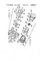
- FIG. 2is an exploded perspective view of a fuseholder according to a first embodiment of the invention, and a fuse.
- FIG. 3is an exploded perspective view of the body portion of the fuseholder shown in FIG. 2.
- FIG. 4is an exploded perspective view of the fuseholder shown in FIG. 2.
- FIG. 5is a sectional view of the first embodiment of the fuseholder shown in FIG. 1.
- FIG. 6is a sectional view taken along line 6--6 in FIG. 5.
- FIG. 7is a sectional view of a second embodiment of a fuseholder as shown in FIG. 1 according to the invention.
- FIG. 1there is shown a fuseholder 10, in perspective, illustrating the external appearance of either of the two preferred embodiments shown in the succeeding figures. Also, since the external appearance, as well as numerous component parts are identical between the two preferred embodiments, identical reference numerals for interchangeable components will be used.
- Fuseholder 10includes a body portion 12 shown as including an enlarged portion 14 and a flange portion 16.
- Flange portion 16is shown as a diamond-shaped flange with mounting holes 18 provided for the passage of fasteners such as screws or rivets to mount fuseholder 10 to a mounting surface or panel.
- Body portion 12has a first end 20, and includes provisions for making electrical connection to a fuse in fuseholder 10 protruding from body portion 12.
- a first connection portion 22 and a second connection portion 24are electrically connected to opposing end caps or ferrules of a fuse member, as will be explained more fully below.
- first end 20 of body portion 12is, in the preferred embodiment, of a square or rectangular cross section, although any desired cross section, such as a cylindrical section may be used, if desired.
- Fuseholder 10also includes a cap portion 26 and a joining portion 28 for joining cap 26 and body 12, which is freely rotatably affixed to cap portion 12 by means of a plurality of mounting fingers 30 which snap into a groove as best shown in FIGS. 5 and 7.
- body portion 12includes an extension portion 32, which includes provisions for the bayonet interlock feature of fuseholder 10a.
- extension portion 32surrounds entrance aperture 34, and defines, on its radial peripheral surface, a plurality of angled or L-shaped slots or grooves 38 appropriate for the female portion of a bayonet interlock.
- the interior surface of extension portion 32also defines a first recess and a pair of second recesses 42.
- Recesses 40 and 42are used to guide and support a second conductive contact portion of which second connection portion 24 is an integral part.
- a fuse member 44having a body portion 46, a first end cap or ferrule 48 and a second end cap or ferrule 50.
- cap portion 26includes a tubular member 52 forming a fuse clip for retaining end cap 50 of fuse 44 to facilitate the insertion and removal of fuses such as fuse 44 into a body portion 12.
- a first conductive contact portion 54includes first connection portion 22 and a fuse member contacting portion 56, and a retaining flange 58.
- First connection portion 22is adapted to receive an electrical connection, such as by a screw, screw and nut, or screw and clamp assembly passed through hole 60, a wire soldered through hole 60, or, preferably, a conventional quick-connect female connector slipped over connection portion 22.
- Portion 56provides a means for conveniently adjusting a fuseholder according to the invention to accept fuse members such as fuse member 44 of differing length.
- first conductive contact portion 54is inserted into body 12 while it is still hot and plastic after molding, retaining flange 58 forming a retaining groove in an interior surface of body portion 12.
- a second conductive contact portion 62is inserted later.
- second conductive contact portion 62includes a generally ring-shaped portion 64, provided with a diverging entrance section 66, and interrupted to form a gap 68.
- Portion 64is also provided with locating tabs 70 which cooperate with grooves 44.
- second conductive contact portionis inserted in body 12 such that second connection portion 24 engages first recess 40, and tabs 70 in gauge second recesses 42, and second connection portion 24 is pushed through aperture 72.
- second connection portion 24is also adapted to receive an electrical connection, such as by a screw, screw and nut or screw and clamp assembly passed through hole 76, a wire soldered through hole 76, or a conventional female quick-connector slipped over second connection portion 24.
- the diameter of inner surface 78 of generally ring-shaped portion 64is chosen to closely receive tubular member 52, for establishing electrical contact between second connector portion 24 and tubular member 52.
- FIG. 4there are shown the individual components of a cap assembly in accordance with the invention, in an exploded view.
- a resilient means for urging a fuse against first conductive contact portion 54 when the fuseholder is assembledis shown as a conical helical spring 80 having an outermost coil 82.
- spring 80is inserted into an axial bore 84 in cap portion 26, preferably at a time when cap portion 26 is still warm and somewhat plastic after molding, and retained by contact of edge 86 of tubular member 52 against outermost coil 82.
- Tubular member 52is preferably inserted into axial bore 84 immediately following the insertion of spring 80.
- Tubular member 52is provided with an indented portion 88, defined by a generally U-shaped slit in tubular member 52.
- This indented portion 88serves to frictionally retain an end cap or ferrule of a fuse, such as end cap 50 of fuse member 44, to facilitate its insertion and removal from the fuseholder.
- joining portion 28ais then freely rotatably mounted on cap portion 26 by positioning joining member 28a so that latching portions 90 of mounting fingers 30 engage groove 92 defined by surface 94 of cap portion 26.
- joining portion 28ahas a knurled or serrated area shown as area 96, to facilitate its manual rotation with respect to cap portion 26.
- this disclosed feature of the inventionis usable with any first body defined by a surface of revolution, such as cap member 26, including an axial bore extending at least partly through the first body, such as axial bore 84, with an annular body such as joining portion 28a adapted to join the first body upon which it is mounted to a second body, which is freely rotatably mounted to the first body by means of a plurality of resilient mounting fingers each including a generally-perpendicular latching portion, such as fingers 30 and portions 90, which cooperate with an annular groove such as groove 92 in an outer surface such as surface 94 of a first body such as cap member 26.
- first conductive contact portion 54is inserted through entrance aperture 34 to first end 20 of body portion 12 while it is still somewhat plastic after molding, so that first connection portion 22 passes through aperture 100, and so that retaining flange 58 forms a retaining groove 102 adjacent first end 20.
- Fuseholder 10ais shown installed through an aperture 104 in a panel 106, and retained either by fasteners passing through mounting holes 18, or, if a suitable shape for flange 16 for mounting holes 18 is not desired, by a retaining means shown as a retaining washer 108 similar in shape to an internal-tooth lock washer applied to enlarged portion 14 adjacent panel 106.
- An O-ring 110is shown placed in a groove 112 in flange portion 16 adjacent panel 106, for forming a waterproof seal between flange portion 16 and panel 106.
- edge 86 of tubular member 52has a tapered area 114 for insertion within inner surface 78 of generally ring-shaped portion 64, to make electrical connection between tubular member 52 and second connector portion 24.
- Cap portion 26, with tubular member 52is retained to and fastened to body portion 12 by a bayonet-lock fastening formed by inwardly-directed protrusions 116 from interior surface 118, cooperating with angled slots formed in exterior surface 122 of extension portion 32, forming a bayonet lock between cap 26 and body portion 12.
- joining portion 28ais freely rotatably mounted to cap 26 by means of latching portions 90 of mounting fingers 30 engaging groove 92.
- An O-ring 124, for forming a waterproof seal between cap 26 and extension portion 32 of body portion 12is shown interposed between end surface 126 of extension portion 32 and stepped portion 128 between surface 94 and a surface 130 of cap portion 26.
- surface 130defines the outer diameter of a pilot portion 132 of cap portion 26 which is received within an inner surface 134 of extension portion 32.
- FIG. 6is a sectional view taken along line 6--6 in FIG. 5, and shows tubular member 52 received within generally ring-shaped portion 64, with locating tabs 70 disposed in second recesses 42, and second connection portion 24 disposed in first recess 40.
- FIG. 7shows a fuseholder 10b, which is similar in all respects other than the configuration of a joining portion 28b and an extension portion 32a, so that otherwise-identical manufacturing and assembly procedures apply. Identical reference numerals are used for identical parts. As can be seen, the only significant difference between FIG. 5 and FIG. 7 is that a screw-type interlock rather than a bayonet-type interlock is provided between cap portion 26 and body portion 12.
- joining portion 28bincludes a screw thread 140 formed or defined in interior surface 118 of joining member 28b, which cooperates with a screw thread 142 formed in exterior surface 122. Screw threads 140 and 142 are of identical pitch diameters and lead, and are preferably multiple-entry screw threads, so that less than a full turn of joining portion 28b is necessary to engage threads 140 and 142.
- a connectionis made to a fuse such as fuse 44, current flowing, for example, from first connection portion 22 to fuse member contacting portion 56, to first end cap 48, through fuse 44 to second end cap 50, and then primarily through conical helical spring 80 to tubular member 52.
- Tubular member 52is in electrical contact with generally ring-shaped portion 64, so that current flows into generally ring-shaped portion 64, and then to second connection portion 24, completing an electrical circuit between connection portions 22 and 24.
Landscapes
- Fuses (AREA)
Abstract
Description
Claims (8)
Priority Applications (2)
| Application Number | Priority Date | Filing Date | Title |
|---|---|---|---|
| US06/367,651US4508413A (en) | 1982-04-12 | 1982-04-12 | Connector |
| CA000423773ACA1197537A (en) | 1982-04-12 | 1983-03-16 | Connector |
Applications Claiming Priority (1)
| Application Number | Priority Date | Filing Date | Title |
|---|---|---|---|
| US06/367,651US4508413A (en) | 1982-04-12 | 1982-04-12 | Connector |
Publications (1)
| Publication Number | Publication Date |
|---|---|
| US4508413Atrue US4508413A (en) | 1985-04-02 |
Family
ID=23448047
Family Applications (1)
| Application Number | Title | Priority Date | Filing Date |
|---|---|---|---|
| US06/367,651Expired - Fee RelatedUS4508413A (en) | 1982-04-12 | 1982-04-12 | Connector |
Country Status (2)
| Country | Link |
|---|---|
| US (1) | US4508413A (en) |
| CA (1) | CA1197537A (en) |
Cited By (39)
| Publication number | Priority date | Publication date | Assignee | Title |
|---|---|---|---|---|
| US4767351A (en)* | 1986-08-13 | 1988-08-30 | G & W Electric Company | High voltage externally-separable bushing |
| USD314943S (en) | 1987-08-19 | 1991-02-26 | Hosiden Electronics Co., Ltd. | Connector socket |
| US5267879A (en)* | 1992-11-03 | 1993-12-07 | Gould Inc. | Panel mount fuse assembly |
| US6049965A (en)* | 1997-07-31 | 2000-04-18 | Liberty Research Company, Inc. | Method and apparatus for machining a workpiece |
| US6744255B1 (en)* | 2002-10-30 | 2004-06-01 | Mcgraw -Edison Company | Grounding device for electric power distribution systems |
| US20070293073A1 (en)* | 2005-11-14 | 2007-12-20 | Hughes David C | Separable loadbreak connector and system |
| US7344421B1 (en)* | 2005-06-06 | 2008-03-18 | Spencer Troy L | Quick release battery cable connector |
| US20080192409A1 (en)* | 2007-02-13 | 2008-08-14 | Paul Michael Roscizewski | Livebreak fuse removal assembly for deadfront electrical apparatus |
| US20080200053A1 (en)* | 2007-02-20 | 2008-08-21 | David Charles Hughes | Thermoplastic interface and shield assembly for separable insulated connector system |
| US20080207022A1 (en)* | 2007-02-22 | 2008-08-28 | David Charles Hughes | Medium voltage separable insulated energized break connector |
| US20080220638A1 (en)* | 2005-08-08 | 2008-09-11 | David Charles Hughes | Apparatus, System and Methods for Deadfront Visible Loadbreak |
| US20080233786A1 (en)* | 2007-03-20 | 2008-09-25 | David Charles Hughes | Separable loadbreak connector and system |
| US20080261465A1 (en)* | 2007-04-23 | 2008-10-23 | Cooper Technologies Company | Separable Insulated Connector System |
| US20080259532A1 (en)* | 2007-04-23 | 2008-10-23 | Cooper Technologies Company | Switchgear Bus Support System and Method |
| US20090060749A1 (en)* | 2007-08-28 | 2009-03-05 | Emerson Climate Technologies, Inc. | Molded Plug For A Compressor |
| US20090100675A1 (en)* | 2007-02-20 | 2009-04-23 | Cooper Technologies Company | Method for manufacturing a shield housing for a separable connector |
| US20090111324A1 (en)* | 2007-02-20 | 2009-04-30 | Cooper Technologies Company | Shield Housing for a Separable Connector |
| US20090108847A1 (en)* | 2007-10-31 | 2009-04-30 | Cooper Technologies Company | Fully Insulated Fuse Test and Ground Device |
| US7578682B1 (en) | 2008-02-25 | 2009-08-25 | Cooper Technologies Company | Dual interface separable insulated connector with overmolded faraday cage |
| US20090215321A1 (en)* | 2008-02-25 | 2009-08-27 | Cooper Technologies Company | Push-then-pull operation of a separable connector system |
| US20090215313A1 (en)* | 2008-02-25 | 2009-08-27 | Cooper Technologies Company | Separable connector with reduced surface contact |
| US20090215299A1 (en)* | 2008-02-27 | 2009-08-27 | Cooper Technologies Company | Two-material separable insulated connector |
| US20090233472A1 (en)* | 2008-03-12 | 2009-09-17 | David Charles Hughes | Electrical Connector with Fault Closure Lockout |
| US20090255106A1 (en)* | 2008-04-11 | 2009-10-15 | Cooper Technologies Company | Method of using an extender for a separable insulated connector |
| US20090258547A1 (en)* | 2008-04-11 | 2009-10-15 | Cooper Technologies Company | Extender for a separable insulated connector |
| US7632120B2 (en) | 2005-07-29 | 2009-12-15 | Cooper Technologies Company | Separable loadbreak connector and system with shock absorbent fault closure stop |
| US7661979B2 (en) | 2007-06-01 | 2010-02-16 | Cooper Technologies Company | Jacket sleeve with grippable tabs for a cable connector |
| US7670162B2 (en) | 2008-02-25 | 2010-03-02 | Cooper Technologies Company | Separable connector with interface undercut |
| US20110076162A1 (en)* | 2009-03-27 | 2011-03-31 | Heidecker Matthew J | Compressor plug assembly |
| US8056226B2 (en) | 2008-02-25 | 2011-11-15 | Cooper Technologies Company | Method of manufacturing a dual interface separable insulated connector with overmolded faraday cage |
| US20120019346A1 (en)* | 2009-04-17 | 2012-01-26 | Bruno Levi | Fuse Holder, Particularly for Interlocked Sockets and Electrical Apparatuses in General |
| US8262372B2 (en) | 2007-05-10 | 2012-09-11 | Emerson Climate Technologies, Inc. | Compressor hermetic terminal |
| US20120282797A1 (en)* | 2011-05-05 | 2012-11-08 | Lear Corporation | Electrically conducting terminal |
| EP2600704A1 (en)* | 2011-12-02 | 2013-06-05 | DET International Holding Limited | Multifunctional changing device |
| US8876562B2 (en) | 2011-05-05 | 2014-11-04 | Lear Corporation | Female type contact for an electrical connector |
| US9325095B2 (en) | 2011-05-05 | 2016-04-26 | Lear Corporation | Female type contact for an electrical connector |
| US9352708B2 (en) | 2011-08-22 | 2016-05-31 | Lear Corporation | Connector assembly and terminal retainer |
| US9480177B2 (en) | 2012-07-27 | 2016-10-25 | Emerson Climate Technologies, Inc. | Compressor protection module |
| CN111681933A (en)* | 2020-07-16 | 2020-09-18 | 国网黑龙江省电力有限公司牡丹江供电公司 | A lower contact of a drop-out fuse and a drop-out fuse containing the lower contact |
Citations (10)
| Publication number | Priority date | Publication date | Assignee | Title |
|---|---|---|---|---|
| US2257608A (en)* | 1937-10-29 | 1941-09-30 | Keefe Arthur | Electrical connection |
| US2813174A (en)* | 1956-03-07 | 1957-11-12 | Howard I Podell | Connector |
| US2851558A (en)* | 1954-07-15 | 1958-09-09 | William C Linton | Fuse holder |
| US3268693A (en)* | 1964-06-17 | 1966-08-23 | Fuse Indicator Corp | Fuseholder |
| US3356806A (en)* | 1965-10-11 | 1967-12-05 | Mc Graw Edison Co | Protectors for electric circuit |
| US3466593A (en)* | 1966-11-14 | 1969-09-09 | Gen Electric | Termination |
| US3471824A (en)* | 1964-04-23 | 1969-10-07 | Bosch Gmbh Robert | Plug and socket connection |
| US3685006A (en)* | 1970-06-24 | 1972-08-15 | Beckman Instruments Inc | Cable connector |
| US3936787A (en)* | 1973-05-30 | 1976-02-03 | Bassani S.P.A. | Cartridge fuse carrier assembly |
| SU788222A1 (en)* | 1979-02-07 | 1980-12-15 | Предприятие П/Я Г-4725 | Fuse holder |
- 1982
- 1982-04-12USUS06/367,651patent/US4508413A/ennot_activeExpired - Fee Related
- 1983
- 1983-03-16CACA000423773Apatent/CA1197537A/ennot_activeExpired
Patent Citations (10)
| Publication number | Priority date | Publication date | Assignee | Title |
|---|---|---|---|---|
| US2257608A (en)* | 1937-10-29 | 1941-09-30 | Keefe Arthur | Electrical connection |
| US2851558A (en)* | 1954-07-15 | 1958-09-09 | William C Linton | Fuse holder |
| US2813174A (en)* | 1956-03-07 | 1957-11-12 | Howard I Podell | Connector |
| US3471824A (en)* | 1964-04-23 | 1969-10-07 | Bosch Gmbh Robert | Plug and socket connection |
| US3268693A (en)* | 1964-06-17 | 1966-08-23 | Fuse Indicator Corp | Fuseholder |
| US3356806A (en)* | 1965-10-11 | 1967-12-05 | Mc Graw Edison Co | Protectors for electric circuit |
| US3466593A (en)* | 1966-11-14 | 1969-09-09 | Gen Electric | Termination |
| US3685006A (en)* | 1970-06-24 | 1972-08-15 | Beckman Instruments Inc | Cable connector |
| US3936787A (en)* | 1973-05-30 | 1976-02-03 | Bassani S.P.A. | Cartridge fuse carrier assembly |
| SU788222A1 (en)* | 1979-02-07 | 1980-12-15 | Предприятие П/Я Г-4725 | Fuse holder |
Cited By (72)
| Publication number | Priority date | Publication date | Assignee | Title |
|---|---|---|---|---|
| US4767351A (en)* | 1986-08-13 | 1988-08-30 | G & W Electric Company | High voltage externally-separable bushing |
| USD314943S (en) | 1987-08-19 | 1991-02-26 | Hosiden Electronics Co., Ltd. | Connector socket |
| US5267879A (en)* | 1992-11-03 | 1993-12-07 | Gould Inc. | Panel mount fuse assembly |
| US6049965A (en)* | 1997-07-31 | 2000-04-18 | Liberty Research Company, Inc. | Method and apparatus for machining a workpiece |
| US6744255B1 (en)* | 2002-10-30 | 2004-06-01 | Mcgraw -Edison Company | Grounding device for electric power distribution systems |
| US7344421B1 (en)* | 2005-06-06 | 2008-03-18 | Spencer Troy L | Quick release battery cable connector |
| US7632120B2 (en) | 2005-07-29 | 2009-12-15 | Cooper Technologies Company | Separable loadbreak connector and system with shock absorbent fault closure stop |
| US20080220638A1 (en)* | 2005-08-08 | 2008-09-11 | David Charles Hughes | Apparatus, System and Methods for Deadfront Visible Loadbreak |
| US20090081896A1 (en)* | 2005-11-14 | 2009-03-26 | Cooper Technologies Company | Separable Electrical Connector with Reduced Risk of Flashover |
| US20070293073A1 (en)* | 2005-11-14 | 2007-12-20 | Hughes David C | Separable loadbreak connector and system |
| US7901227B2 (en) | 2005-11-14 | 2011-03-08 | Cooper Technologies Company | Separable electrical connector with reduced risk of flashover |
| US20110081793A1 (en)* | 2005-11-14 | 2011-04-07 | Cooper Technologies Company | Separable Electrical Connector with Reduced Risk of Flashover |
| US7572133B2 (en) | 2005-11-14 | 2009-08-11 | Cooper Technologies Company | Separable loadbreak connector and system |
| US8038457B2 (en) | 2005-11-14 | 2011-10-18 | Cooper Technologies Company | Separable electrical connector with reduced risk of flashover |
| US20080192409A1 (en)* | 2007-02-13 | 2008-08-14 | Paul Michael Roscizewski | Livebreak fuse removal assembly for deadfront electrical apparatus |
| US7854620B2 (en) | 2007-02-20 | 2010-12-21 | Cooper Technologies Company | Shield housing for a separable connector |
| US7494355B2 (en) | 2007-02-20 | 2009-02-24 | Cooper Technologies Company | Thermoplastic interface and shield assembly for separable insulated connector system |
| US20090100675A1 (en)* | 2007-02-20 | 2009-04-23 | Cooper Technologies Company | Method for manufacturing a shield housing for a separable connector |
| US20090111324A1 (en)* | 2007-02-20 | 2009-04-30 | Cooper Technologies Company | Shield Housing for a Separable Connector |
| US20080200053A1 (en)* | 2007-02-20 | 2008-08-21 | David Charles Hughes | Thermoplastic interface and shield assembly for separable insulated connector system |
| US20080207022A1 (en)* | 2007-02-22 | 2008-08-28 | David Charles Hughes | Medium voltage separable insulated energized break connector |
| US7950939B2 (en) | 2007-02-22 | 2011-05-31 | Cooper Technologies Company | Medium voltage separable insulated energized break connector |
| US20080233786A1 (en)* | 2007-03-20 | 2008-09-25 | David Charles Hughes | Separable loadbreak connector and system |
| US7862354B2 (en) | 2007-03-20 | 2011-01-04 | Cooper Technologies Company | Separable loadbreak connector and system for reducing damage due to fault closure |
| US7666012B2 (en) | 2007-03-20 | 2010-02-23 | Cooper Technologies Company | Separable loadbreak connector for making or breaking an energized connection in a power distribution network |
| US20080261465A1 (en)* | 2007-04-23 | 2008-10-23 | Cooper Technologies Company | Separable Insulated Connector System |
| US7568927B2 (en) | 2007-04-23 | 2009-08-04 | Cooper Technologies Company | Separable insulated connector system |
| US20080259532A1 (en)* | 2007-04-23 | 2008-10-23 | Cooper Technologies Company | Switchgear Bus Support System and Method |
| US7633741B2 (en) | 2007-04-23 | 2009-12-15 | Cooper Technologies Company | Switchgear bus support system and method |
| US8262372B2 (en) | 2007-05-10 | 2012-09-11 | Emerson Climate Technologies, Inc. | Compressor hermetic terminal |
| US20100240245A1 (en)* | 2007-06-01 | 2010-09-23 | Cooper Technologies Company | Jacket Sleeve with Grippable Tabs for a Cable Connector |
| US7883356B2 (en) | 2007-06-01 | 2011-02-08 | Cooper Technologies Company | Jacket sleeve with grippable tabs for a cable connector |
| US7661979B2 (en) | 2007-06-01 | 2010-02-16 | Cooper Technologies Company | Jacket sleeve with grippable tabs for a cable connector |
| US7909635B2 (en) | 2007-06-01 | 2011-03-22 | Cooper Technologies Company | Jacket sleeve with grippable tabs for a cable connector |
| US20090060749A1 (en)* | 2007-08-28 | 2009-03-05 | Emerson Climate Technologies, Inc. | Molded Plug For A Compressor |
| US8939734B2 (en) | 2007-08-28 | 2015-01-27 | Emerson Climate Technologies, Inc. | Molded plug for a compressor |
| US20090108847A1 (en)* | 2007-10-31 | 2009-04-30 | Cooper Technologies Company | Fully Insulated Fuse Test and Ground Device |
| US7695291B2 (en) | 2007-10-31 | 2010-04-13 | Cooper Technologies Company | Fully insulated fuse test and ground device |
| US7578682B1 (en) | 2008-02-25 | 2009-08-25 | Cooper Technologies Company | Dual interface separable insulated connector with overmolded faraday cage |
| US20090215321A1 (en)* | 2008-02-25 | 2009-08-27 | Cooper Technologies Company | Push-then-pull operation of a separable connector system |
| US8056226B2 (en) | 2008-02-25 | 2011-11-15 | Cooper Technologies Company | Method of manufacturing a dual interface separable insulated connector with overmolded faraday cage |
| US20090215313A1 (en)* | 2008-02-25 | 2009-08-27 | Cooper Technologies Company | Separable connector with reduced surface contact |
| US7905735B2 (en) | 2008-02-25 | 2011-03-15 | Cooper Technologies Company | Push-then-pull operation of a separable connector system |
| US7670162B2 (en) | 2008-02-25 | 2010-03-02 | Cooper Technologies Company | Separable connector with interface undercut |
| US7950940B2 (en) | 2008-02-25 | 2011-05-31 | Cooper Technologies Company | Separable connector with reduced surface contact |
| US20090215299A1 (en)* | 2008-02-27 | 2009-08-27 | Cooper Technologies Company | Two-material separable insulated connector |
| US8109776B2 (en) | 2008-02-27 | 2012-02-07 | Cooper Technologies Company | Two-material separable insulated connector |
| US8152547B2 (en) | 2008-02-27 | 2012-04-10 | Cooper Technologies Company | Two-material separable insulated connector band |
| US7811113B2 (en) | 2008-03-12 | 2010-10-12 | Cooper Technologies Company | Electrical connector with fault closure lockout |
| US20090233472A1 (en)* | 2008-03-12 | 2009-09-17 | David Charles Hughes | Electrical Connector with Fault Closure Lockout |
| US7878849B2 (en) | 2008-04-11 | 2011-02-01 | Cooper Technologies Company | Extender for a separable insulated connector |
| US20090255106A1 (en)* | 2008-04-11 | 2009-10-15 | Cooper Technologies Company | Method of using an extender for a separable insulated connector |
| US7958631B2 (en) | 2008-04-11 | 2011-06-14 | Cooper Technologies Company | Method of using an extender for a separable insulated connector |
| US20090258547A1 (en)* | 2008-04-11 | 2009-10-15 | Cooper Technologies Company | Extender for a separable insulated connector |
| US8939735B2 (en) | 2009-03-27 | 2015-01-27 | Emerson Climate Technologies, Inc. | Compressor plug assembly |
| US20110076162A1 (en)* | 2009-03-27 | 2011-03-31 | Heidecker Matthew J | Compressor plug assembly |
| US20120019346A1 (en)* | 2009-04-17 | 2012-01-26 | Bruno Levi | Fuse Holder, Particularly for Interlocked Sockets and Electrical Apparatuses in General |
| US8614619B2 (en)* | 2009-04-17 | 2013-12-24 | Palazzoli S.P.A. | Fuse holder, particularly for interlocked sockets and electrical apparatuses in general |
| CN103907243B (en)* | 2011-05-05 | 2015-12-02 | 李尔公司 | Conductive terminal |
| US9356377B2 (en) | 2011-05-05 | 2016-05-31 | Lear Corporation | Electrically conducting terminal |
| US8876562B2 (en) | 2011-05-05 | 2014-11-04 | Lear Corporation | Female type contact for an electrical connector |
| CN103907243A (en)* | 2011-05-05 | 2014-07-02 | 李尔公司 | Conductive terminal |
| US8840436B2 (en)* | 2011-05-05 | 2014-09-23 | Lear Corporation | Electrically conducting terminal |
| US20120282797A1 (en)* | 2011-05-05 | 2012-11-08 | Lear Corporation | Electrically conducting terminal |
| US9325095B2 (en) | 2011-05-05 | 2016-04-26 | Lear Corporation | Female type contact for an electrical connector |
| US9761983B2 (en) | 2011-08-22 | 2017-09-12 | Lear Corporation | Connector assembly and terminal retainer |
| US9352708B2 (en) | 2011-08-22 | 2016-05-31 | Lear Corporation | Connector assembly and terminal retainer |
| EP2600704A1 (en)* | 2011-12-02 | 2013-06-05 | DET International Holding Limited | Multifunctional changing device |
| US9480177B2 (en) | 2012-07-27 | 2016-10-25 | Emerson Climate Technologies, Inc. | Compressor protection module |
| US10028399B2 (en) | 2012-07-27 | 2018-07-17 | Emerson Climate Technologies, Inc. | Compressor protection module |
| US10485128B2 (en) | 2012-07-27 | 2019-11-19 | Emerson Climate Technologies, Inc. | Compressor protection module |
| CN111681933A (en)* | 2020-07-16 | 2020-09-18 | 国网黑龙江省电力有限公司牡丹江供电公司 | A lower contact of a drop-out fuse and a drop-out fuse containing the lower contact |
Also Published As
| Publication number | Publication date |
|---|---|
| CA1197537A (en) | 1985-12-03 |
Similar Documents
| Publication | Publication Date | Title |
|---|---|---|
| US4508413A (en) | Connector | |
| EP2722937B1 (en) | Connector assembly | |
| US5021010A (en) | Soldered connector for a shielded coaxial cable | |
| US3325775A (en) | Electrical terminal | |
| EP0525854B1 (en) | Light socket | |
| US2869097A (en) | Electrical lamp socket | |
| EP0986841B1 (en) | Fuseholder and connector | |
| US6379197B2 (en) | Terminal connector | |
| US4428034A (en) | Light bulb mounting unit | |
| US4842541A (en) | Electrical connector | |
| CA2140059C (en) | Multi-wire locking system | |
| US3465279A (en) | Miniature pin terminal connector | |
| EP0009349B1 (en) | Electrical cartridge fuse connector | |
| US4504815A (en) | Miniature fuseholder | |
| US5176536A (en) | Right angle phone plug | |
| CA1191529A (en) | Fuse holder | |
| US5063659A (en) | Method of joining a soldered connector to a shielded coaxial cable | |
| US5562482A (en) | Coaxial cable connector and method of assembling | |
| US7070440B1 (en) | Coaxial cable insulation displacement connector | |
| US4544226A (en) | Two-piece clamp shell for electric cigar lighter | |
| US5176532A (en) | Threaded receptacle method and device | |
| US4239313A (en) | Swivel connector | |
| US3688248A (en) | Roller metal pin for use as electric connector or fastener | |
| US3320607A (en) | Housing for indicating lamp or other electrical components | |
| US4968269A (en) | Fuse holder |
Legal Events
| Date | Code | Title | Description |
|---|---|---|---|
| AS | Assignment | Owner name:ELTRA CORPORATION, A CORP. OF DEL. Free format text:ASSIGNMENT OF ASSIGNORS INTEREST.;ASSIGNOR:BAILEY, WILLIAM;REEL/FRAME:003991/0304 Effective date:19820529 Owner name:ELTRA CORPORATION, OHIO Free format text:ASSIGNMENT OF ASSIGNORS INTEREST;ASSIGNOR:BAILEY, WILLIAM;REEL/FRAME:003991/0304 Effective date:19820529 | |
| AS | Assignment | Owner name:ALLIED CORPORATION; COLUMBIA RD. AND PARK AVE., MO Free format text:ASSIGNMENT OF ASSIGNORS INTEREST.;ASSIGNOR:ELTRA CORPORATION;REEL/FRAME:004026/0293 Effective date:19820531 Owner name:ALLIED CORPORATION, NEW JERSEY Free format text:ASSIGNMENT OF ASSIGNORS INTEREST;ASSIGNOR:ELTRA CORPORATION;REEL/FRAME:004026/0293 Effective date:19820531 | |
| FEPP | Fee payment procedure | Free format text:PAYOR NUMBER ASSIGNED (ORIGINAL EVENT CODE: ASPN); ENTITY STATUS OF PATENT OWNER: LARGE ENTITY | |
| AS | Assignment | Owner name:CANADIAN IMPERIAL BANK OF COMMERCE, NEW YORK AGENC Free format text:SECURITY INTEREST;ASSIGNOR:AMPHENOL CORPORATION;REEL/FRAME:004879/0030 Effective date:19870515 | |
| AS | Assignment | Owner name:MCGRAW-EDISON COMPANY, 1001 FANNIN, SUITE 4000, HO Free format text:ASSIGNMENT OF ASSIGNORS INTEREST.;ASSIGNOR:AMPHENOL CORPORATION;REEL/FRAME:004740/0302 Effective date:19870717 Owner name:MCGRAW-EDISON COMPANY,TEXAS Free format text:ASSIGNMENT OF ASSIGNORS INTEREST;ASSIGNOR:AMPHENOL CORPORATION;REEL/FRAME:004740/0302 Effective date:19870717 | |
| AS | Assignment | Owner name:AMPHENOL CORPORATION, LISLE, ILLINOIS A CORP. OF D Free format text:ASSIGNMENT OF ASSIGNORS INTEREST.;ASSIGNOR:ALLIED CORPORATION, A CORP. OF NY;REEL/FRAME:004844/0850 Effective date:19870602 Owner name:AMPHENOL CORPORATION, A CORP. OF DE, ILLINOIS Free format text:ASSIGNMENT OF ASSIGNORS INTEREST;ASSIGNOR:ALLIED CORPORATION, A CORP. OF NY;REEL/FRAME:004844/0850 Effective date:19870602 | |
| FPAY | Fee payment | Year of fee payment:4 | |
| AS | Assignment | Owner name:AMPHENOL CORPORATION A CORP. OF DELAWARE Free format text:RELEASED BY SECURED PARTY;ASSIGNOR:CANADIAN IMPERIAL BANK OF COMMERCE;REEL/FRAME:006147/0887 Effective date:19911114 | |
| REMI | Maintenance fee reminder mailed | ||
| LAPS | Lapse for failure to pay maintenance fees | ||
| FP | Lapsed due to failure to pay maintenance fee | Effective date:19930404 | |
| AS | Assignment | Owner name:BEHRING DIAGNOSTICS GMBH, GERMANY Free format text:ASSIGNMENT OF ASSIGNORS INTEREST;ASSIGNOR:BEHRINGWERKE AKTIENGESELLSCHAFT;REEL/FRAME:009168/0310 Effective date:19970721 Owner name:BEHRING DIAGNOSTICS GMBH, GERMANY Free format text:ASSIGNMENT OF ASSIGNORS INTEREST;ASSIGNOR:BEHRINGWERKE AKTIENGESELLSCHAFT;REEL/FRAME:009507/0015 Effective date:19970721 Owner name:BEHRING DIAGNOSTICS GMBH,GERMANY Free format text:ASSIGNMENT OF ASSIGNORS INTEREST;ASSIGNOR:BEHRINGWERKE AKTIENGESELLSCHAFT;REEL/FRAME:009168/0310 Effective date:19970721 | |
| STCH | Information on status: patent discontinuation | Free format text:PATENT EXPIRED DUE TO NONPAYMENT OF MAINTENANCE FEES UNDER 37 CFR 1.362 |