US4508111A - Adjustable splint - Google Patents
Adjustable splintDownload PDFInfo
- Publication number
- US4508111A US4508111AUS06/484,439US48443983AUS4508111AUS 4508111 AUS4508111 AUS 4508111AUS 48443983 AUS48443983 AUS 48443983AUS 4508111 AUS4508111 AUS 4508111A
- Authority
- US
- United States
- Prior art keywords
- adjustable
- struts
- strut
- spring
- splint assembly
- Prior art date
- Legal status (The legal status is an assumption and is not a legal conclusion. Google has not performed a legal analysis and makes no representation as to the accuracy of the status listed.)
- Expired - Lifetime
Links
- 230000003014reinforcing effectEffects0.000claims1
- 210000003127kneeAnatomy0.000description37
- 208000006111contractureDiseases0.000description32
- 210000003414extremityAnatomy0.000description32
- 206010062575Muscle contractureDiseases0.000description18
- 230000007246mechanismEffects0.000description11
- 230000000712assemblyEffects0.000description6
- 238000000429assemblyMethods0.000description6
- 210000001513elbowAnatomy0.000description6
- 210000003811fingerAnatomy0.000description6
- 210000000707wristAnatomy0.000description6
- 230000006835compressionEffects0.000description4
- 238000007906compressionMethods0.000description4
- 230000005021gaitEffects0.000description4
- 208000014674injuryDiseases0.000description4
- 208000027418Wounds and injuryDiseases0.000description3
- 244000309466calfSpecies0.000description3
- 238000010276constructionMethods0.000description3
- 230000006378damageEffects0.000description3
- 210000000629knee jointAnatomy0.000description3
- 210000003141lower extremityAnatomy0.000description3
- 239000004033plasticSubstances0.000description3
- 238000001356surgical procedureMethods0.000description3
- 210000001519tissueAnatomy0.000description3
- 210000000689upper legAnatomy0.000description3
- 208000010428Muscle WeaknessDiseases0.000description2
- 206010028372Muscular weaknessDiseases0.000description2
- 238000003745diagnosisMethods0.000description2
- 230000000694effectsEffects0.000description2
- 239000002184metalSubstances0.000description2
- 210000003314quadriceps muscleAnatomy0.000description2
- 238000012549trainingMethods0.000description2
- 210000001364upper extremityAnatomy0.000description2
- 238000003466weldingMethods0.000description2
- 206010065433Ligament ruptureDiseases0.000description1
- 230000009286beneficial effectEffects0.000description1
- 238000004140cleaningMethods0.000description1
- 230000006735deficitEffects0.000description1
- 238000011161developmentMethods0.000description1
- 230000002401inhibitory effectEffects0.000description1
- 238000003780insertionMethods0.000description1
- 230000037431insertionEffects0.000description1
- 210000002414legAnatomy0.000description1
- 239000003562lightweight materialSubstances0.000description1
- 239000000463materialSubstances0.000description1
- 238000000034methodMethods0.000description1
- 230000001483mobilizing effectEffects0.000description1
- 238000012986modificationMethods0.000description1
- 230000004048modificationEffects0.000description1
- 210000003205muscleAnatomy0.000description1
- 230000008439repair processEffects0.000description1
- 238000009958sewingMethods0.000description1
- 238000004904shorteningMethods0.000description1
- 229910001220stainless steelInorganic materials0.000description1
- 239000010935stainless steelSubstances0.000description1
- 230000008736traumatic injuryEffects0.000description1
- 230000002792vascularEffects0.000description1
- 239000002023woodSubstances0.000description1
Images


Classifications
- A—HUMAN NECESSITIES
- A61—MEDICAL OR VETERINARY SCIENCE; HYGIENE
- A61F—FILTERS IMPLANTABLE INTO BLOOD VESSELS; PROSTHESES; DEVICES PROVIDING PATENCY TO, OR PREVENTING COLLAPSING OF, TUBULAR STRUCTURES OF THE BODY, e.g. STENTS; ORTHOPAEDIC, NURSING OR CONTRACEPTIVE DEVICES; FOMENTATION; TREATMENT OR PROTECTION OF EYES OR EARS; BANDAGES, DRESSINGS OR ABSORBENT PADS; FIRST-AID KITS
- A61F5/00—Orthopaedic methods or devices for non-surgical treatment of bones or joints; Nursing devices ; Anti-rape devices
- A61F5/01—Orthopaedic devices, e.g. long-term immobilising or pressure directing devices for treating broken or deformed bones such as splints, casts or braces
- A61F5/0102—Orthopaedic devices, e.g. long-term immobilising or pressure directing devices for treating broken or deformed bones such as splints, casts or braces specially adapted for correcting deformities of the limbs or for supporting them; Ortheses, e.g. with articulations
- A61F2005/0132—Additional features of the articulation
- A61F2005/0165—Additional features of the articulation with limits of movement
- A61F2005/0167—Additional features of the articulation with limits of movement adjustable
- A—HUMAN NECESSITIES
- A61—MEDICAL OR VETERINARY SCIENCE; HYGIENE
- A61F—FILTERS IMPLANTABLE INTO BLOOD VESSELS; PROSTHESES; DEVICES PROVIDING PATENCY TO, OR PREVENTING COLLAPSING OF, TUBULAR STRUCTURES OF THE BODY, e.g. STENTS; ORTHOPAEDIC, NURSING OR CONTRACEPTIVE DEVICES; FOMENTATION; TREATMENT OR PROTECTION OF EYES OR EARS; BANDAGES, DRESSINGS OR ABSORBENT PADS; FIRST-AID KITS
- A61F5/00—Orthopaedic methods or devices for non-surgical treatment of bones or joints; Nursing devices ; Anti-rape devices
- A61F5/01—Orthopaedic devices, e.g. long-term immobilising or pressure directing devices for treating broken or deformed bones such as splints, casts or braces
- A61F5/0102—Orthopaedic devices, e.g. long-term immobilising or pressure directing devices for treating broken or deformed bones such as splints, casts or braces specially adapted for correcting deformities of the limbs or for supporting them; Ortheses, e.g. with articulations
- A61F2005/0132—Additional features of the articulation
- A61F2005/0179—Additional features of the articulation with spring means
Definitions
- This inventionrelates to an adjustable splint. More particularly, this invention relates to an adjustable splint useful in treating impairments in body joints such as knees, elbows, wrists, fingers, backs and the like from flexion or extension contracture, weakness in the supporting musculature, or some other malady inhibiting the integrity of the body joint in accomplishing extension of flexion.
- extension contracturesin the fingers, wrists, elbows, knees and other joints from many and various causes. Weakness, disuse, fractures, surgeries, traumatic injuries, illness and other causes have been known to cause loss of ability to flex the body joint otherwise known as an extension contracture. No device presently exists to reduce extension contractures by adjustable, quantifiable pressure as does the adjustable splint for flexion described herein.
- splint devices and mechanismshave been designed to be influential at the knee either for support or for mobilizing the knee joint.
- Illustrative of such devicesare those described in U.S. Pat. Nos. 3,055,359; 3,928,872; 3,785,372 and 3,799,159.
- all of these devicesare not designed to reduce knee flexion or extension contractures or cannot be tolerated by the patient population for a long enough period to effectively reduce a contracture.
- none of the devicesoffer a satisfactory means for adjusting the pressure exerted by the lateral struts of the splint devices.
- an object of the inventionto provide an improved splint device for reducing flexion or extension contractures about a body joint such as a knee, elbow, finger or wrist.
- Another object of the inventionis to provide a splint device which will shorten the rehabilitation time of individuals that are bedridden or incapacitated due to flexion or extension contractures about a joint.
- Yet another object of the inventionis to provide a split device, which allows easy gradual adjustment to the quantifiable force desired on an extremity acting across a body joint.
- a further object of the inventionis to provide a splint device for incarcerated patients to help obtain a higher level of independence in their activities of daily living, self care and ambulatory activities.
- a further objectwould be to provide an improved splint for providing support to a limb around a body joint such as a knee, elbow, wrist or finger, in cases where muscular weakness exists.
- an adjustable splint assemblycomprising a lower strut and an upper strut pivotably connected to said lower strut, one of said struts having at one end a pivotably mounted head portion defining a cam surface, an adjustable biasing means mounted within the other strut and biased into engagement with said cam surface, for applying a quantifiable force tending to approximate or align said upper and lower struts and means for securing said splint assembly to a limb.
- the present inventioncomprises a pair of lowr struts and a pair of upper struts, each member of the pair of upper struts, said members of each pair being spaced apart a distance to accomodate limb parts distal and proximal to the limb joint, at least one of said struts having at one end, a pivotably mounted head portion defining a cam surface, an adjustable biasing means mounted within the strut pivotably connected to said cam surface-containing strut and biased into engagement with said cam surface, for applying a quantifiable force tending to align or approximate the cam surface-containing strut with the adjustable biasing means containing strut and means provided said pair of upper struts and said pair of lower struts for securely holding therebetween said distal and proximal parts of a limb.
- the splint deviceis provided with telescoping wire assembly on the upper and lower struts whereby the splint device is secured to the limbs.
- This slidably adjustable wire assembly featureenables the splint device of the invention to accomodate various limb lengths.
- novel snap-on comfort pads attachable to the struts of the splint deviceprovide greater patient comfort.
- Another aspect of the inventioninvolves a novel cuff for attaching the splint device to a limb which cuff is designed to accomodate limbs of varying circumference.
- FIG. 1is a perspective view of the adjustable splint for reducing flexion contractures
- FIG. 2is a perspective view of one upper and one lower strut assembly of the adjustable splint of the invention for reducing flexion contractures wherein a strut is broken away to show the adjustable spring-loaded means mounted therein;
- FIG. 3is a perspective, exploded view of the splint device of FIG. 1;
- FIG. 4is a perspective view of the splint device provided with a "break apart" wire assembly for mounting of the means by which the device is secured to the limb;
- FIG. 5is a cuff designed for attachment to the wire assembly shown in FIG. 4;
- FIG. 6is a perspective view of one upper and one lower strut assembly of the adjustable splint of the invention for reducing extension contractures wherein a strut is broken away to show the adjustable spring-loaded means mounted therein;
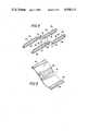
- FIG. 7is a perspective view of the splint device provided with a telescoping slidable adjustable wire assembly for mounting of the means by which the device is secured to the limb;
- FIG. 8is a plan view of the outside of another cuff for attachment to the wire assembly designed to accomodate limbs of varying circumferences;
- FIG. 9is a perspective view of the cuff shown in FIG. 9;
- FIG. 10is a perspective view of a wedge-type comfort pad for use in combination with the adjustable splint of the invention.
- FIG. 11is a perspective view of a rectangular-type comfort pads for use in combination with the adjustable splint of the invention.
- an adjustable splint device 1is comprised of lower struts 3 and 3a and upper struts 5 and 5a.
- Lower strut 3contains a rounded head portion 7 and upper strut 5 contains a socket head portion 9 which receives head portion 7 for pivotable engagement therewith.
- Rounded head portion 7is cut away to define a cam surface 10 and is provided with an axial surface recess 13.
- a first surface plate 15 having a screw hole 17covers one side of the combined head portions 7-9 and a second plate member 18 having a threaded protruding member 19 (see FIG. 3) covers the other half of the combined head portion 7-9.
- protruding member 19projects through the axial circular recess 13 and receives a screw 21 through screw hole 17.
- Lower strut 3a and upper strut 5aare similarly pivotably connected by corresponding members bearing like numbers but carrying the distinguishing suffix "a".
- the lower and upper strutsmay be constructed of any material of sufficient strength such as plastic, metal, wood and the like. Particularly preferred are struts made of stainless steel metal. At least one of the struts should be at least partially hollow so as to house therein the adjustable spring mechanism of the invention. Most advantageously, all of the struts are tubular in construction so as to provide a lightweight product. Preferably each of the struts 3, 3a, 5 and 5a can be comprised of two telescoping portions as shown in the single strut depicted in FIG. 7 so as to permit lengthening and shortening of the struts. Directing attention to FIG.
- strut 3is comprised of telescoping portions 4 and 4', strut 5 of telescoping portions 6 and 6'.
- the inner portions 4 and 6are provided with a series of threaded holes 8 and 8a and the outer portions 4' and 6' with holes and threaded holes, respectively, through which screws 12 pass for threaded engagement with a coincident hole 8 and 8a.
- the distal strutis of larger diameter than the proximal strut as shown in FIG. 7 it is preferable to provide threads in the holes of the outer portion 6'.
- Such a telescoping featureprovides a splint which can be adjusted to several different lengths allowing the splint to fit a greater number of individuals.
- the splint device combination of the inventionwill include a series of spring abutting members 20 (see FIG. 3) of varying lengths so as to accomodate different limb lengths.
- the adjustable spring-loaded mechanism designated generally as 20may be provided in either the lower or the upper struts. Preferably, only the lower struts 5 and 5a are provided with the adjustable spring mechanism.
- the adjustable spring mechanism 20is comprised of a spring 22 to which is attached a nose element 24 that bears on cam surface 10.
- Coil or clock springsare generally preferred but in some instances leaf springs are advantageously employed, particularly in small devices such as finger or wrist splints.
- An adjustable screw means indicated generally as 25abuts the other end of the spring 22 and produces a quantifiable force which tends to either extend, (i.e. align the lower strut 5 with the upper strut 3 and lower strut 5a with upper strut 3a in a parallel fashion) as shown in FIG. 2 or to approximate (i.e. bring together the lower strut 5 with the upper strut 3 and lower strut 5a with upper strut 3a) as shown in FIG. 6.
- the adjustable screw means 25is comprised of an "Allen” head screw or slotted head screw 27 threaded to a spring-abutting member 29.
- the "Allen” head screwis fixed within upper strut 3 by screw 33.
- the "Allen” head screw 27receives and is turned by an "Allen” socket wrench 32 (see FIG. 1) whereas a slotted head screw is adjustable with a conventional screwdriver blade.
- the turning of the screwcreates greater compression of spring 22 thereby exerting greater force on the cam surface 10 of the lower strut 5 to exert a one way tension.
- the tension capability of the spring mechanismcan range from 0 pounds tension up to the maximum tension capable of the spring. In general, the tension of the spring mechanism will range from 0 pounds tension up to 10 pounds of tension and the tension exerted by the spring can be varied at any point of joint range of motion, say from 60° flexion to 0° flexion of the joint.
- the joint range of motion at which tension can be appliedcan vary to nearly any degree in the 360° circular range simply by varying the point of attachment of the inner portion of the strut 3 to rounded head portion 7 and by varying the point of attachment of the inner portion of strut 5 to socket head portion 9.
- the same variationsapply to struts 3a and 5a.
- the purpose of varying the point in the joint range to which tension is appliedis obvious when you consider that different illnesses and injuries cause different types of limitations at different degrees of joint ranges of motion thereby making necessary different points in the joint range at which tension must be applied to improve their condition.
- Another examplewould be when reducing an extension contracture of the knee the desired range of motion to which tension would be applied would range from 40° flexion to 130° flexion.
- the spring mechanismcan be calibrated to exert this range of tension.
- the calibrationcan be effected by providing spring-abutting member 29 with a poundage indicator line 35 and a calibration scale 37 about the lower strut 5 which scale has a slot 39 through which the poundage indicator 35 is visible.
- the securing meanscomprise a proximal cuff 41 attached to and extending between upper strut 3a and upper strut 3 and distal cuff 43 attached to and extending between lower strut 5a and lower strut 5.
- the length of the proximal cuff 41 and distal cuff 43is of sufficient distance to comfortably accomodate the limb parts distal and proximal to the limb joint.
- An overlying flap 45is attached at one end to upper strut 3a and contains on its outer surface an attaching means such as velcro hooks 46 by which the flap can wrap about the proximal portion of the limb and be secured to the velcro loops 47 on the outer surface of the proximal cuff wrapped about upper strut 3.
- Distal cuff 43is secured to lower strut 5a and 5 and contains two separate flaps 49 and 51 each containing on their outside velcro attaching loops 53 and 55 respectively.
- the flaps 49 and 51are of sufficient length to extend over and secure the limb portion lying in distal cuff 43 by attachment to the velcro loops receiving areas 57 and 59 provided on the distal cuff 43 about the lower strut 5.
- a single combined strutsuch as upper strut 3 pivotably connected to lower strut 5, can alone be utilized as a splint device by securing same by suitable means to the lateral side of the limb to be treated.
- any suitable means for strapping or securing the splint device of the inventioncan be used, for example, by distal and proximal cuffs of sufficient lengths to wrap around the distal and proximal portions of the limb being treated.
- the straps 45, 49 and 51 as well as the cuffs 41 and 43can be secured to the struts in any suitable manner as by sewing, tying, etc.
- wire assembliesdesignated generally in FIG. 4 as 60, 62, 64 and 66, be fastened as by welding to struts 5, 5a and 3 and 3a, respectively.
- the wire assembly 62is comprised of an upper thin wire portion 83 and a thin wire lower portion 82, each of which wire assembly portions extend from one end of strut 3a to the other.
- wire assembly 60is comprised of an upper thin wire portion 86 and a lower wire portion 87.
- the shorter sides of the wire assembliesare of continuous construction and bent for more secure attachment as by welding to the struts.
- FIG. 7the shorter sides of the wire assemblies are of continuous construction and bent for more secure attachment as by welding to the struts.
- wire assemblies 64 and 66differ from wire assemblies 60 and 62 in being of the "break apart" type as will be explained below so as to facilitate insertion and removal of the cuffs or straps for cleaning, replacing, etc.
- wire assembly 66is comprised of an upper thin wire portion 80 and a lower thin wire portion 81 both of which are broken at 87 and 88, respectively, so that the wire can be pulled apart slightly when the cuff or straps are to be attached or removed.
- wire assembly 64is comprised of a thin upper wire section 84 and a thin lower wire section 85 both of which are broken at 89 and 90, respectively.
- wire assembliesare of "break apart" type but one, wire portion on both the distal and proximal struts, that is, two of the four receiving wires contains telescoping sections B and B'. Telescoping sections B and B' are internally threaded at one end for engagement with threaded end 11 and 11' or the wire portion. This gives the wire fixture added strength. Normally a wire assembly with telescoping sections B and B', however, is only used n the side of the strut which makes an angle of 65° when flexed.
- a strap 110is provided between struts 3 and 3a as shown in FIG. 4 and between 5 and 5a.
- Use of a strap 110 both between struts 3 and 3a and 5 and 5ais often advisable in many instances particularly in reducing knee flexion contractures.
- Strap 110 in these applicationsis important in order to maintain optimal alignment of the upper and lower struts along the parallel of the limb part proximal and distal to the joint. Strap 110 also helps maintain the axis of rotation of the splint joint assembly more coincident with the axis of rotation of the body joint to which the splint is being applied.
- Attachment of cuff 92, provided with velcro hooks section 98 and a velcro loop section 100 as shown in FIG. 5, to the wire assemblies shown in FIG. 4may then be conducted in the following manner:
- Loop end section 94 of cuff 92is put on wire portion 80 via break 87 with the velcro hooks section 98 and velcro loop section 100 facing outward.
- Edge 96is taken over the limb and fed through and under wire portion 83 of wire assembly 62, and then put back on itself whereby velcro hooks 98 adhere to velcro loops 100. This secures one of the four cuffs needed to fix the splint assembly to a limb about a joint.
- a cuffis attached to wire sections 84 and 86 in a similar manner. The same procedure is used to attach cuffs or straps to the wire sections 81-82 and wire sections 85-87.
- securing meanssuch as velcro hooks and loops.
- securing meansare shown to be velcro closures other alternative closures, such as snaps and the like can be provided the straps and cuffs.
- FIGS. 8 and 9Another novel cuff which can be used to secure the splint device to the limb is shown in FIGS. 8 and 9.
- the cuff 120is of a length sufficient to accomodate limb parts distal and proximal to the limb joint.
- the outside of cuff 120is composed of a spaced part and alternating velcro loop section 122 and a velcro hook section 124 each followed by a zone therebetween containing both velcro hook sections and velcro loop sections.
- the zones containing both hook sections and loop sectionsare comprised of an intermediate area 128 constituted of a velcro loop or hook section identical to the preceding section flanked on each side by areas having velcro loop or hook sections identical to the section of uniform velcro hooks or loops that follows.
- the zone following velcro loop sectionis composed of an intermediate velcro loops area 128 flanked on each side by velcro hook areas 126.
- Velcro hook section 124is followed by a zone having a velcro hook area 132 flanked by velcro loop areas 133. If a longer cuff is required the next zone would be of velcro loops only, etc.
- Loop end section 134 of cuff 120is provided with a stay-receiving means indicated generally as 136 into which is inserted a plastic stay 137 to prevent any collapsing that is likely to occur during use. Also, the inside of cuff 120 contains multiple stay receiving means 138.
- the cuffis shown in the figures as rectangular in shape. It should be understood, however, that the cuff can assume various curved configurations so as to conform to the particular limb to which it is attached. Attachment of cuff 120 to the wire assembly and the patient limb can be effected as described above.
- the splint deviceis provided with snap-on comfort pads shown in FIGS. 10 and 11.
- the comfort padsare of two types, the wedge-type of FIG. 10 and the rectangular-type of FIG. 11.
- the wedge-type comfort pad of FIG. 10is composed of a wedge base 135 provided with a snap-on section comprised of a base plate 140 containing spaced snap-on elements 142 and 142'.
- the rectangular-type comfort pad of FIG. 11is composed of a base plate 147 and snap-on elements 149 and 149'.
- the wedge base 135 and rectangular base 145may be constructed of any suitable light weight material such as foamed plastic.
- wedge-type comfort padsare used only when the adjustable splint of the invention is applied to the lower extremities, e.g. thigh and leg.
- two wedge-type comfort padsare normally snapped onto the distal and proximal struts, respectively, within the wire assembly and between the limb and strut in a fashion whereby the thick portion of each wedge is proximal to the point of pivotable engagement of said struts.
- the rectangular comfort padsare similarly snapped on the struts within the wire assembly and between the limb and the strut.
- two of the rectangular comfort padswill be placed on the lateral side of the lower extremities, one on the proximal strut and the other on the distal strut.
- the rectangular-type comfort padwill be used exclusively. In this case, normally four of the rectangular-type comfort pads will be snapped onto the distal and proximal struts as set forth above, both on the lateral and medial side of the upper extremity.
- the unique characteristics of the adjustable springloaded mechanism of the present inventionis that is allows for adjustment of quantifiable force on an extremity acting across the body joint from 0 foot poundage up to the maximum foot poundage at various body joint ranges.
- the same tensioncould be dialed into the splint at the angle just as could be done at 30° and just as could be done at 10° knee flexion contracture.
- any force up to maximum capability of the spring employed in the strutcan be dialed at any angle of knee flexion.
- the inventionpermits the interchangability of springs bearing force-exerting capabilities so as to allow for varying the degrees of tension exerted by the spring mechanism depending upon the particular use to which the device is applied.
- the adjustable splint for flexion of a jointmight be used, one may consider an extension contracture, i.e. loss of ability to flex the joint through the normal range of motion, of any particular body joint such as the knee, elbow, wrist, fingers, etc. For simplicity the knee joint will be used.
- an extension contracturei.e. loss of ability to flex the joint through the normal range of motion, of any particular body joint such as the knee, elbow, wrist, fingers, etc.
- the knee jointwill be used.
- a knee extension contracturewhether the contracture is of a muscle or joint type, the individual may be able to flex the knee to 45° and no further.
- Applying the adjustable splint for flexionwould be useful in that a forco would be exerted on the body parts proximal and distal to the knee which would tend to approximate the calf to the posterior thigh.
- the force exerted by the splintwould be adjustable from 0 foot pounds of torque across the knee joint to upward torque of whatever tension capability the particular spring being used would have. Surmising a reasonable force would be to have an upper limit of 10-20 foot pounds acting at mid calf and/or mid thigh.
- the exact tension desiredwould be determined by factors such as patient tolerance, type and age of the contracture, skin compliance, diagnosis, etc.
- a unique feature of this device in the present application to the knee, and to any body joint,is the ability of this device to allow graduated, quantified, adjustable tension with the ability to relax the stretch across the joint by extending the knee away from the limit of flexion. This will allow the tissue being stretched to have a rest period while not disturbing the adjustment of the spring tension and without having to remove the splint.
- the tension in the splintIn order to relieve the pressure on the contractured tissues, one merely has to overcome, by any means, the tension in the splint and extend the joint to a comfortable posture. Once a short rest is achieved, the splint may again exert its tension against the contractured tissue to help accomplish a greater degree of flexion in the joint.
- flexionwould advance from the point of contracture, say 45° flexion, to the upper theoretical limits of flexion which, binding any other negating factors, would be 135°-150°. Time necessary to accomplish the optimal result using this splint would vary depending on many factors, some of which are the patient's diagnosis, age of patient, age of the contracture and tolerance of the patient.
Landscapes
- Health & Medical Sciences (AREA)
- Nursing (AREA)
- Orthopedic Medicine & Surgery (AREA)
- Engineering & Computer Science (AREA)
- Biomedical Technology (AREA)
- Heart & Thoracic Surgery (AREA)
- Vascular Medicine (AREA)
- Life Sciences & Earth Sciences (AREA)
- Animal Behavior & Ethology (AREA)
- General Health & Medical Sciences (AREA)
- Public Health (AREA)
- Veterinary Medicine (AREA)
- Orthopedics, Nursing, And Contraception (AREA)
Abstract
Description
Claims (24)
Priority Applications (1)
| Application Number | Priority Date | Filing Date | Title |
|---|---|---|---|
| US06/484,439US4508111A (en) | 1981-07-23 | 1983-04-13 | Adjustable splint |
Applications Claiming Priority (2)
| Application Number | Priority Date | Filing Date | Title |
|---|---|---|---|
| US06/286,161US4397308A (en) | 1981-07-23 | 1981-07-23 | Adjustable splint |
| US06/484,439US4508111A (en) | 1981-07-23 | 1983-04-13 | Adjustable splint |
Related Parent Applications (2)
| Application Number | Title | Priority Date | Filing Date |
|---|---|---|---|
| US06/286,161Continuation-In-PartUS4397308A (en) | 1981-07-23 | 1981-07-23 | Adjustable splint |
| US06/367,598Continuation-In-PartUS4485808A (en) | 1981-07-23 | 1982-04-12 | Adjustable splint |
Related Child Applications (1)
| Application Number | Title | Priority Date | Filing Date |
|---|---|---|---|
| US06/638,766DivisionUS4657000A (en) | 1981-07-23 | 1984-08-08 | Adjustable splint and securing means therefor |
Publications (1)
| Publication Number | Publication Date |
|---|---|
| US4508111Atrue US4508111A (en) | 1985-04-02 |
Family
ID=26963636
Family Applications (1)
| Application Number | Title | Priority Date | Filing Date |
|---|---|---|---|
| US06/484,439Expired - LifetimeUS4508111A (en) | 1981-07-23 | 1983-04-13 | Adjustable splint |
Country Status (1)
| Country | Link |
|---|---|
| US (1) | US4508111A (en) |
Cited By (58)
| Publication number | Priority date | Publication date | Assignee | Title |
|---|---|---|---|---|
| US4944290A (en)* | 1988-08-09 | 1990-07-31 | Dynasplint Systems, Inc. | Adjustable splint |
| US4961416A (en)* | 1989-06-12 | 1990-10-09 | Orthopedic Systems, Inc. | Knee brace |
| US5002044A (en)* | 1989-10-10 | 1991-03-26 | Carter Peter R | Derotation wrist brace |
| US5036837A (en)* | 1990-02-09 | 1991-08-06 | Bio-Tec, Inc. | Dynamic extension splint |
| US5052379A (en)* | 1989-04-27 | 1991-10-01 | Soma Dynamics Corporation | Combination brace and wearable exercise apparatus for body joints |
| US5103811A (en)* | 1990-07-09 | 1992-04-14 | Crupi Jr Theodore P | Body part or joint brace |
| US5167612A (en)* | 1990-07-30 | 1992-12-01 | Bonutti Peter M | Adjustable orthosis |
| US5213094A (en)* | 1990-07-30 | 1993-05-25 | Bonutti Peter M | Orthosis with joint distraction |
| US5285773A (en)* | 1990-07-30 | 1994-02-15 | Peter M. Bonutti | Orthosis with distraction through range of motion |
| US5306230A (en)* | 1992-09-23 | 1994-04-26 | Rob Bodine/Capra Research | Knee extending orthotic appliance |
| US5358469A (en)* | 1990-02-09 | 1994-10-25 | Ultraflex Systems, Inc. | Dynamic splint |
| US5399154A (en)* | 1993-06-30 | 1995-03-21 | Empi, Inc. | Constant torque range-of-motion splint |
| US5437619A (en)* | 1993-06-30 | 1995-08-01 | Empi, Inc. | Range-of-motion splint with eccentric spring |
| US5472410A (en)* | 1994-04-22 | 1995-12-05 | Deroyal/Lmb, Inc. | Adjustable flexion and extension joint orthoses |
| US5520627A (en)* | 1993-06-30 | 1996-05-28 | Empi, Inc. | Range-of-motion ankle splint |
| US5571078A (en)* | 1993-06-30 | 1996-11-05 | Empi, Inc. | Range-of-motion ankle splint |
| US5575764A (en)* | 1994-12-14 | 1996-11-19 | Van Dyne; Leonard A. | Prosthetic joint with dynamic torque compensator |
| US5658241A (en)* | 1990-02-09 | 1997-08-19 | Ultraflex Systems, Inc. | Multi-functional dynamic splint |
| US5685830A (en)* | 1990-07-30 | 1997-11-11 | Bonutti; Peter M. | Adjustable orthosis having one-piece connector section for flexing |
| US5749840A (en)* | 1989-12-07 | 1998-05-12 | Ultraflex Systems, Inc. | Dynamic splint |
| US5759165A (en)* | 1993-06-30 | 1998-06-02 | Empi, Inc. | Forearm supination range-of-motion orthosis |
| US5891061A (en)* | 1997-02-20 | 1999-04-06 | Jace Systems, Inc. | Brace for applying a dynamic force to a jointed limb |
| US5954621A (en)* | 1993-07-09 | 1999-09-21 | Kinetecs, Inc. | Exercise apparatus and technique |
| US5980435A (en)* | 1993-07-09 | 1999-11-09 | Kinetecs, Inc. | Methods of therapy or controlled exercise using a jointed brace |
| US6001075A (en)* | 1997-12-12 | 1999-12-14 | Ex. P.H. | Dynamic splint |
| USD450851S1 (en) | 2000-11-03 | 2001-11-20 | Milton Herndon | Shin splint prevention device |
| US6533741B1 (en) | 2000-01-06 | 2003-03-18 | Roger W. Lee | Articulated upper extremity splint to immobilize and support an injured limb |
| US20040158184A1 (en)* | 2003-01-16 | 2004-08-12 | Davis Perry H. | Orthopedic splint |
| EP1479360A1 (en)* | 2003-05-09 | 2004-11-24 | Otto Bock HealthCare GmbH | Orthopaedic brace |
| WO2005034798A3 (en)* | 2003-10-02 | 2005-08-18 | Dynasplint Systems Inc | Adjustable splint device for relieving contractures |
| US20060036205A1 (en)* | 2000-12-15 | 2006-02-16 | Bonutti Peter M | Myofascial strap |
| USD530820S1 (en)* | 2004-06-28 | 2006-10-24 | Otto Bock Healthcare Gmbh | Orthotic device |
| US20060271112A1 (en)* | 2004-11-15 | 2006-11-30 | Martinson James B | Instrumented orthopedic and other medical implants |
| US20070155588A1 (en)* | 1998-09-01 | 2007-07-05 | Izex Technologies, Inc. | Remote monitoring of a patient |
| US20070270976A1 (en)* | 2002-04-25 | 2007-11-22 | Ultraflex Systems, Inc. | Ambulating ankle & knee joints with bidirectional dampening and assistance using elastomeric restraint |
| US20080091132A1 (en)* | 2000-12-01 | 2008-04-17 | Bonutti Peter M | Neck brace and method of using same to treat spinal disc disorders |
| US20090030353A1 (en)* | 2007-07-25 | 2009-01-29 | Bonutti Peter M | Orthosis Apparatus and Method of Using an Orthosis Apparatus |
| US20090036814A1 (en)* | 2000-09-18 | 2009-02-05 | Bonutti Peter M | Finger orthosis |
| US20090099492A1 (en)* | 2007-10-11 | 2009-04-16 | Saebo, Inc. | Splint assembly for positioning of the hand |
| US20090198162A1 (en)* | 2002-04-25 | 2009-08-06 | Ultraflex Sytems, Inc. | Ambulating knee joint |
| US20100121160A1 (en)* | 1999-06-23 | 2010-05-13 | Izex Technologies, Inc. | Remote psychological evaluation |
| US7955285B2 (en) | 1998-06-01 | 2011-06-07 | Bonutti Research Inc. | Shoulder orthosis |
| US7981067B2 (en) | 2004-03-08 | 2011-07-19 | Bonutti Research Inc. | Range of motion device |
| US8012108B2 (en) | 2005-08-12 | 2011-09-06 | Bonutti Research, Inc. | Range of motion system and method |
| US8066656B2 (en) | 2005-10-28 | 2011-11-29 | Bonutti Research, Inc. | Range of motion device |
| US8784475B2 (en) | 2004-11-15 | 2014-07-22 | Izex Technologies, Inc. | Instrumented implantable stents, vascular grafts and other medical devices |
| US8905950B2 (en) | 2008-03-04 | 2014-12-09 | Bonutti Research, Inc. | Shoulder ROM orthosis |
| US8920346B2 (en) | 2007-02-05 | 2014-12-30 | Bonutti Research Inc. | Knee orthosis |
| US9402759B2 (en) | 2013-02-05 | 2016-08-02 | Bonutti Research, Inc. | Cervical traction systems and method |
| US9763821B2 (en) | 2011-10-31 | 2017-09-19 | Ossur Iceland Ehf | Orthopedic device for dynamically treating the knee |
| US10143581B2 (en) | 2013-06-21 | 2018-12-04 | Ossur Hf | Dynamic tension system for orthopedic device |
| US10413437B2 (en) | 2013-01-25 | 2019-09-17 | Ossur Iceland Ehf | Orthopedic device having a dynamic control system and method for using the same |
| US10617550B2 (en) | 2014-06-28 | 2020-04-14 | Breg, Inc. | Knee brace having a variable tensioning offset cam |
| US10653546B2 (en) | 2014-10-31 | 2020-05-19 | Ossur Hf | Orthopedic device having a dynamic control system |
| US11458032B2 (en) | 2014-06-28 | 2022-10-04 | Sports Medicine Sciences, LLC | Anatomical brace for dynamically stabilizing the patella during knee articulation so as to address patella tracking error |
| US11547590B2 (en) | 2017-11-27 | 2023-01-10 | Ossur Iceland Ehf | Orthopedic device having a suspension element |
| US11737903B2 (en) | 2017-07-28 | 2023-08-29 | Sports Medicine Sciences, LLC | Anatomical brace for dynamically stabilizing the elbow |
| US12011381B2 (en) | 2014-06-28 | 2024-06-18 | Sports Medicine Sciences, LLC | Anatomical brace for dynamically stabilizing the patella during knee articulation so as to address patella tracking error |
Citations (3)
| Publication number | Priority date | Publication date | Assignee | Title |
|---|---|---|---|---|
| US2661000A (en)* | 1951-06-25 | 1953-12-01 | William E Gazeley | Surgical splint |
| GB830507A (en)* | 1955-02-14 | 1960-03-16 | Frances Ellen Suter | Improved caliper joints for orthopaedic splints |
| US3548817A (en)* | 1968-04-29 | 1970-12-22 | Ronald F Mittasch | Orthopedic traction belt |
- 1983
- 1983-04-13USUS06/484,439patent/US4508111A/ennot_activeExpired - Lifetime
Patent Citations (3)
| Publication number | Priority date | Publication date | Assignee | Title |
|---|---|---|---|---|
| US2661000A (en)* | 1951-06-25 | 1953-12-01 | William E Gazeley | Surgical splint |
| GB830507A (en)* | 1955-02-14 | 1960-03-16 | Frances Ellen Suter | Improved caliper joints for orthopaedic splints |
| US3548817A (en)* | 1968-04-29 | 1970-12-22 | Ronald F Mittasch | Orthopedic traction belt |
Cited By (96)
| Publication number | Priority date | Publication date | Assignee | Title |
|---|---|---|---|---|
| US4944290A (en)* | 1988-08-09 | 1990-07-31 | Dynasplint Systems, Inc. | Adjustable splint |
| US5052379A (en)* | 1989-04-27 | 1991-10-01 | Soma Dynamics Corporation | Combination brace and wearable exercise apparatus for body joints |
| US4961416A (en)* | 1989-06-12 | 1990-10-09 | Orthopedic Systems, Inc. | Knee brace |
| US5002044A (en)* | 1989-10-10 | 1991-03-26 | Carter Peter R | Derotation wrist brace |
| US5749840A (en)* | 1989-12-07 | 1998-05-12 | Ultraflex Systems, Inc. | Dynamic splint |
| US5358469A (en)* | 1990-02-09 | 1994-10-25 | Ultraflex Systems, Inc. | Dynamic splint |
| US5036837A (en)* | 1990-02-09 | 1991-08-06 | Bio-Tec, Inc. | Dynamic extension splint |
| US5658241A (en)* | 1990-02-09 | 1997-08-19 | Ultraflex Systems, Inc. | Multi-functional dynamic splint |
| US5103811A (en)* | 1990-07-09 | 1992-04-14 | Crupi Jr Theodore P | Body part or joint brace |
| US5395303A (en)* | 1990-07-30 | 1995-03-07 | Peter M. Bonutti | Orthosis with distraction through range of motion |
| US5611764A (en)* | 1990-07-30 | 1997-03-18 | Peter M. Bonutti | Method of increasing range of motion |
| US5365947A (en)* | 1990-07-30 | 1994-11-22 | Bonutti Peter M | Adjustable orthosis |
| US5685830A (en)* | 1990-07-30 | 1997-11-11 | Bonutti; Peter M. | Adjustable orthosis having one-piece connector section for flexing |
| US5167612A (en)* | 1990-07-30 | 1992-12-01 | Bonutti Peter M | Adjustable orthosis |
| US5453075A (en)* | 1990-07-30 | 1995-09-26 | Peter M. Bonutti | Orthosis with distraction through range of motion |
| US5456268A (en)* | 1990-07-30 | 1995-10-10 | Bonutti; Peter M. | Adjustable orthosis |
| US5285773A (en)* | 1990-07-30 | 1994-02-15 | Peter M. Bonutti | Orthosis with distraction through range of motion |
| US5213094A (en)* | 1990-07-30 | 1993-05-25 | Bonutti Peter M | Orthosis with joint distraction |
| US5306230A (en)* | 1992-09-23 | 1994-04-26 | Rob Bodine/Capra Research | Knee extending orthotic appliance |
| US5399154A (en)* | 1993-06-30 | 1995-03-21 | Empi, Inc. | Constant torque range-of-motion splint |
| US5759165A (en)* | 1993-06-30 | 1998-06-02 | Empi, Inc. | Forearm supination range-of-motion orthosis |
| US5571078A (en)* | 1993-06-30 | 1996-11-05 | Empi, Inc. | Range-of-motion ankle splint |
| US5520627A (en)* | 1993-06-30 | 1996-05-28 | Empi, Inc. | Range-of-motion ankle splint |
| US5437619A (en)* | 1993-06-30 | 1995-08-01 | Empi, Inc. | Range-of-motion splint with eccentric spring |
| US5954621A (en)* | 1993-07-09 | 1999-09-21 | Kinetecs, Inc. | Exercise apparatus and technique |
| US5980435A (en)* | 1993-07-09 | 1999-11-09 | Kinetecs, Inc. | Methods of therapy or controlled exercise using a jointed brace |
| US5472410A (en)* | 1994-04-22 | 1995-12-05 | Deroyal/Lmb, Inc. | Adjustable flexion and extension joint orthoses |
| US5683353A (en)* | 1994-04-22 | 1997-11-04 | Deroyal/Lmb, Inc. | Adjustable flexion and extension joint orthoses |
| US5624390A (en)* | 1994-12-14 | 1997-04-29 | Van Dyne; Leonard A. | Prosthetic joint with dynamic torque compensator |
| US5575764A (en)* | 1994-12-14 | 1996-11-19 | Van Dyne; Leonard A. | Prosthetic joint with dynamic torque compensator |
| US5891061A (en)* | 1997-02-20 | 1999-04-06 | Jace Systems, Inc. | Brace for applying a dynamic force to a jointed limb |
| US6001075A (en)* | 1997-12-12 | 1999-12-14 | Ex. P.H. | Dynamic splint |
| US7955285B2 (en) | 1998-06-01 | 2011-06-07 | Bonutti Research Inc. | Shoulder orthosis |
| US8678979B2 (en) | 1998-09-01 | 2014-03-25 | Izex Technologies, Inc. | Remote monitoring of a patient |
| US9230057B2 (en) | 1998-09-01 | 2016-01-05 | Izex Technologies, Inc. | Remote monitoring of a patient |
| US20070155588A1 (en)* | 1998-09-01 | 2007-07-05 | Izex Technologies, Inc. | Remote monitoring of a patient |
| US20100121160A1 (en)* | 1999-06-23 | 2010-05-13 | Izex Technologies, Inc. | Remote psychological evaluation |
| US8790258B2 (en) | 1999-06-23 | 2014-07-29 | Izex Technologies, Inc. | Remote psychological evaluation |
| US6533741B1 (en) | 2000-01-06 | 2003-03-18 | Roger W. Lee | Articulated upper extremity splint to immobilize and support an injured limb |
| US8038637B2 (en) | 2000-09-18 | 2011-10-18 | Bonutti Research, Inc. | Finger orthosis |
| US20090036814A1 (en)* | 2000-09-18 | 2009-02-05 | Bonutti Peter M | Finger orthosis |
| USD450851S1 (en) | 2000-11-03 | 2001-11-20 | Milton Herndon | Shin splint prevention device |
| US20080091132A1 (en)* | 2000-12-01 | 2008-04-17 | Bonutti Peter M | Neck brace and method of using same to treat spinal disc disorders |
| US9681977B2 (en) | 2000-12-01 | 2017-06-20 | Bonutti Research, Inc. | Apparatus and method for spinal distraction |
| US8251934B2 (en) | 2000-12-01 | 2012-08-28 | Bonutti Research, Inc. | Orthosis and method for cervical mobilization |
| US8062241B2 (en) | 2000-12-15 | 2011-11-22 | Bonutti Research Inc | Myofascial strap |
| US20060036205A1 (en)* | 2000-12-15 | 2006-02-16 | Bonutti Peter M | Myofascial strap |
| US8123709B2 (en) | 2002-04-25 | 2012-02-28 | Ultraflex Systems, Inc. | Ambulating knee joint |
| US20070270976A1 (en)* | 2002-04-25 | 2007-11-22 | Ultraflex Systems, Inc. | Ambulating ankle & knee joints with bidirectional dampening and assistance using elastomeric restraint |
| US8100844B2 (en) | 2002-04-25 | 2012-01-24 | Ultraflex Systems, Inc. | Ambulating ankle and knee joints with bidirectional dampening and assistance using elastomeric restraint |
| US20090198162A1 (en)* | 2002-04-25 | 2009-08-06 | Ultraflex Sytems, Inc. | Ambulating knee joint |
| US6936020B2 (en) | 2003-01-16 | 2005-08-30 | Perry H. Davis | Orthopedic splint |
| US20040158184A1 (en)* | 2003-01-16 | 2004-08-12 | Davis Perry H. | Orthopedic splint |
| US20040260220A1 (en)* | 2003-05-09 | 2004-12-23 | Helmut Wagner | Joint orthosis |
| EP1479360A1 (en)* | 2003-05-09 | 2004-11-24 | Otto Bock HealthCare GmbH | Orthopaedic brace |
| US7413555B2 (en) | 2003-05-09 | 2008-08-19 | Otto Bock Healthcare Gmbh | Joint orthosis |
| US6942629B2 (en) | 2003-10-02 | 2005-09-13 | Dynasplint Systems, Inc. | Adjustable splint device for relieving contractures |
| WO2005034798A3 (en)* | 2003-10-02 | 2005-08-18 | Dynasplint Systems Inc | Adjustable splint device for relieving contractures |
| US9314392B2 (en) | 2004-03-08 | 2016-04-19 | Bonutti Research, Inc. | Range of motion device |
| US9445966B2 (en) | 2004-03-08 | 2016-09-20 | Bonutti Research, Inc. | Range of motion device |
| US7981067B2 (en) | 2004-03-08 | 2011-07-19 | Bonutti Research Inc. | Range of motion device |
| USD530820S1 (en)* | 2004-06-28 | 2006-10-24 | Otto Bock Healthcare Gmbh | Orthotic device |
| US20060271112A1 (en)* | 2004-11-15 | 2006-11-30 | Martinson James B | Instrumented orthopedic and other medical implants |
| US8491572B2 (en) | 2004-11-15 | 2013-07-23 | Izex Technologies, Inc. | Instrumented orthopedic and other medical implants |
| US8740879B2 (en) | 2004-11-15 | 2014-06-03 | Izex Technologies, Inc. | Instrumented orthopedic and other medical implants |
| US8784475B2 (en) | 2004-11-15 | 2014-07-22 | Izex Technologies, Inc. | Instrumented implantable stents, vascular grafts and other medical devices |
| US8012108B2 (en) | 2005-08-12 | 2011-09-06 | Bonutti Research, Inc. | Range of motion system and method |
| US9320669B2 (en) | 2005-08-12 | 2016-04-26 | Bonutti Research, Inc. | Range of motion system |
| US8784343B2 (en) | 2005-08-12 | 2014-07-22 | Bonutti Research, Inc. | Range of motion system |
| US9468578B2 (en) | 2005-10-28 | 2016-10-18 | Bonutti Research Inc. | Range of motion device |
| US10456314B2 (en) | 2005-10-28 | 2019-10-29 | Bonutti Research, Inc. | Range of motion device |
| US8066656B2 (en) | 2005-10-28 | 2011-11-29 | Bonutti Research, Inc. | Range of motion device |
| US8920346B2 (en) | 2007-02-05 | 2014-12-30 | Bonutti Research Inc. | Knee orthosis |
| US9980871B2 (en) | 2007-02-05 | 2018-05-29 | Bonutti Research, Inc. | Knee orthosis |
| US8273043B2 (en) | 2007-07-25 | 2012-09-25 | Bonutti Research, Inc. | Orthosis apparatus and method of using an orthosis apparatus |
| US20090030353A1 (en)* | 2007-07-25 | 2009-01-29 | Bonutti Peter M | Orthosis Apparatus and Method of Using an Orthosis Apparatus |
| US8784348B2 (en) | 2007-10-11 | 2014-07-22 | Saebo, Inc. | Splint assembly for positioning of the hand |
| US8070702B2 (en) | 2007-10-11 | 2011-12-06 | Saebo, Inc. | Splint assembly for positioning of the hand |
| US20090099492A1 (en)* | 2007-10-11 | 2009-04-16 | Saebo, Inc. | Splint assembly for positioning of the hand |
| US8905950B2 (en) | 2008-03-04 | 2014-12-09 | Bonutti Research, Inc. | Shoulder ROM orthosis |
| US9763821B2 (en) | 2011-10-31 | 2017-09-19 | Ossur Iceland Ehf | Orthopedic device for dynamically treating the knee |
| US9770356B2 (en) | 2011-10-31 | 2017-09-26 | Ossur Hf | Orthopedic device for dynamically treating the knee |
| US10898363B2 (en) | 2011-10-31 | 2021-01-26 | Ossur Hf | Orthopedic device for dynamically treating the knee |
| US10413437B2 (en) | 2013-01-25 | 2019-09-17 | Ossur Iceland Ehf | Orthopedic device having a dynamic control system and method for using the same |
| US11464662B2 (en) | 2013-01-25 | 2022-10-11 | Ossur Iceland Ehf | Orthopedic device having a dynamic control system and method for using the same |
| US9402759B2 (en) | 2013-02-05 | 2016-08-02 | Bonutti Research, Inc. | Cervical traction systems and method |
| US10143581B2 (en) | 2013-06-21 | 2018-12-04 | Ossur Hf | Dynamic tension system for orthopedic device |
| US11160679B2 (en) | 2013-06-21 | 2021-11-02 | Ossur Hf | Dynamic tension system for orthopedic device |
| US11458032B2 (en) | 2014-06-28 | 2022-10-04 | Sports Medicine Sciences, LLC | Anatomical brace for dynamically stabilizing the patella during knee articulation so as to address patella tracking error |
| US10617550B2 (en) | 2014-06-28 | 2020-04-14 | Breg, Inc. | Knee brace having a variable tensioning offset cam |
| US12011381B2 (en) | 2014-06-28 | 2024-06-18 | Sports Medicine Sciences, LLC | Anatomical brace for dynamically stabilizing the patella during knee articulation so as to address patella tracking error |
| US10653546B2 (en) | 2014-10-31 | 2020-05-19 | Ossur Hf | Orthopedic device having a dynamic control system |
| US11628081B2 (en) | 2014-10-31 | 2023-04-18 | Ossur Hf | Orthopedic device having a dynamic control system |
| US11737903B2 (en) | 2017-07-28 | 2023-08-29 | Sports Medicine Sciences, LLC | Anatomical brace for dynamically stabilizing the elbow |
| US12290462B2 (en) | 2017-07-28 | 2025-05-06 | Sports Medicine Sciences, LLC | Anatomical brace for dynamically stabilizing the elbow |
| US11547590B2 (en) | 2017-11-27 | 2023-01-10 | Ossur Iceland Ehf | Orthopedic device having a suspension element |
Similar Documents
| Publication | Publication Date | Title |
|---|---|---|
| US4508111A (en) | Adjustable splint | |
| US4657000A (en) | Adjustable splint and securing means therefor | |
| US4485808A (en) | Adjustable splint | |
| US4538600A (en) | Adjustable splint | |
| US4397308A (en) | Adjustable splint | |
| US5014690A (en) | Adjustable splint | |
| US4947835A (en) | Adjustable splint assembly | |
| EP0277663B1 (en) | Adjustable splint | |
| US5232436A (en) | Extension block finger splint | |
| US5213094A (en) | Orthosis with joint distraction | |
| US6723061B2 (en) | Dynamic splint for carpal tunnel syndrome treatment | |
| US5873847A (en) | Articulated splints and goniometric hinge for the same | |
| US5437611A (en) | Dynamic brace joint | |
| US6306111B1 (en) | Rehabilitative shoulder support | |
| US4715363A (en) | Knee brace with extension angle establishing means | |
| JPS60500847A (en) | external brace device | |
| US4945902A (en) | Progressive static flexion device for phalanges | |
| US4944290A (en) | Adjustable splint | |
| US3714940A (en) | Hand brace | |
| US5070868A (en) | Adjustable splint | |
| CA1237617A (en) | Adjustable splint | |
| WO2001017467A1 (en) | Dynamic splint for carpal tunnel syndrome treatment | |
| JPH04502419A (en) | Adjustable splint assembly | |
| JPH01121047A (en) | Aid apparatus for cubitus joint |
Legal Events
| Date | Code | Title | Description |
|---|---|---|---|
| AS | Assignment | Owner name:DYNASPLINT SYSTEMS, INC., 606 HAMMONDS LANE, SUITE Free format text:ASSIGNMENT OF ASSIGNORS INTEREST.;ASSIGNOR:HEPBURN, GEORGE R.;REEL/FRAME:004314/0364 Effective date:19840928 Owner name:DYNASPLINT SYSTEMS, INC.,MARYLAND Free format text:ASSIGNMENT OF ASSIGNORS INTEREST;ASSIGNOR:HEPBURN, GEORGE R.;REEL/FRAME:004314/0364 Effective date:19840928 | |
| STCF | Information on status: patent grant | Free format text:PATENTED CASE | |
| FEPP | Fee payment procedure | Free format text:PAT HOLDER CLAIMS SMALL ENTITY STATUS - SMALL BUSINESS (ORIGINAL EVENT CODE: SM02); ENTITY STATUS OF PATENT OWNER: SMALL ENTITY Free format text:PAYOR NUMBER ASSIGNED (ORIGINAL EVENT CODE: ASPN); ENTITY STATUS OF PATENT OWNER: SMALL ENTITY | |
| FPAY | Fee payment | Year of fee payment:4 | |
| AS | Assignment | Owner name:FIRST NATIONAL BANK OF MARYLAND, THE, MARYLAND Free format text:ASSIGNMENT OF ASSIGNORS INTEREST.;ASSIGNOR:DYNASPLINT SYSTEMS, INC.;REEL/FRAME:005336/0484 Effective date:19900502 | |
| AS | Assignment | Owner name:SIGNET BANK/MARYLAND A MARYLAND BANKING CORPORA Free format text:SECURITY INTEREST;ASSIGNOR:DYNASPLINT SYSTEMS, INC. A MARYLAND CORPORATION;REEL/FRAME:005711/0501 Effective date:19910509 | |
| FEPP | Fee payment procedure | Free format text:PAYOR NUMBER ASSIGNED (ORIGINAL EVENT CODE: ASPN); ENTITY STATUS OF PATENT OWNER: SMALL ENTITY Free format text:PAYER NUMBER DE-ASSIGNED (ORIGINAL EVENT CODE: RMPN); ENTITY STATUS OF PATENT OWNER: SMALL ENTITY | |
| FPAY | Fee payment | Year of fee payment:8 | |
| FPAY | Fee payment | Year of fee payment:12 | |
| SULP | Surcharge for late payment | ||
| REMI | Maintenance fee reminder mailed | ||
| AS | Assignment | Owner name:FINOVA CAPITAL CORPORATION, CALIFORNIA Free format text:SECURITY AGREEMENT;ASSIGNOR:DYNASPLINT SYSTEMS, INC.;REEL/FRAME:009146/0662 Effective date:19980220 |