US4506679A - Endocardial electrode - Google Patents
Endocardial electrodeDownload PDFInfo
- Publication number
- US4506679A US4506679AUS06/430,912US43091282AUS4506679AUS 4506679 AUS4506679 AUS 4506679AUS 43091282 AUS43091282 AUS 43091282AUS 4506679 AUS4506679 AUS 4506679A
- Authority
- US
- United States
- Prior art keywords
- tine
- electrode tip
- tip
- improvement
- electrode
- Prior art date
- Legal status (The legal status is an assumption and is not a legal conclusion. Google has not performed a legal analysis and makes no representation as to the accuracy of the status listed.)
- Expired - Lifetime
Links
- 239000004020conductorSubstances0.000claimsabstractdescription31
- 239000000463materialSubstances0.000claimsabstractdescription31
- 230000000903blocking effectEffects0.000claimsabstractdescription22
- 210000001124body fluidAnatomy0.000claimsabstractdescription10
- 239000010839body fluidSubstances0.000claimsabstractdescription10
- 230000001154acute effectEffects0.000claimsdescription8
- 210000005003heart tissueAnatomy0.000claimsdescription5
- OCDRLZFZBHZTKQ-NMUBGGKPSA-NonetineChemical compoundC[C@@H](O)[C@@]1(O)C[C@@H](C)[C@@](C)(O)C(=O)OC\C2=C\CN(C)CC[C@@H](OC1=O)C2=OOCDRLZFZBHZTKQ-NMUBGGKPSA-N0.000claimsdescription4
- 238000005452bendingMethods0.000claimsdescription2
- 239000012811non-conductive materialSubstances0.000claimsdescription2
- 230000035515penetrationEffects0.000claimsdescription2
- 230000001747exhibiting effectEffects0.000claims3
- 210000003462veinAnatomy0.000abstractdescription11
- 230000003247decreasing effectEffects0.000abstractdescription3
- 230000000452restraining effectEffects0.000description21
- 238000003780insertionMethods0.000description7
- 230000037431insertionEffects0.000description7
- 239000004814polyurethaneSubstances0.000description3
- 229920002379silicone rubberPolymers0.000description3
- 239000004945silicone rubberSubstances0.000description3
- 239000011810insulating materialSubstances0.000description2
- 238000012986modificationMethods0.000description2
- 230000004048modificationEffects0.000description2
- 229920003225polyurethane elastomerPolymers0.000description2
- 238000004026adhesive bondingMethods0.000description1
- 238000005520cutting processMethods0.000description1
- 238000004519manufacturing processMethods0.000description1
- 239000007769metal materialSubstances0.000description1
- 238000000034methodMethods0.000description1
- 239000004033plasticSubstances0.000description1
- 229920003023plasticPolymers0.000description1
- 229920002635polyurethanePolymers0.000description1
- 239000012858resilient materialSubstances0.000description1
- 239000007787solidSubstances0.000description1
- 230000004936stimulating effectEffects0.000description1
- 210000001519tissueAnatomy0.000description1
Images

Classifications
- A—HUMAN NECESSITIES
- A61—MEDICAL OR VETERINARY SCIENCE; HYGIENE
- A61N—ELECTROTHERAPY; MAGNETOTHERAPY; RADIATION THERAPY; ULTRASOUND THERAPY
- A61N1/00—Electrotherapy; Circuits therefor
- A61N1/02—Details
- A61N1/04—Electrodes
- A61N1/05—Electrodes for implantation or insertion into the body, e.g. heart electrode
- A61N1/056—Transvascular endocardial electrode systems
- A61N1/057—Anchoring means; Means for fixing the head inside the heart
Definitions
- the inventionrelates to medical electrodes, and more particularly to endocardial electrodes having outwardly extending tines located near an electrode tip.
- Endocardial electrodesinclude an exposed metallic electrode tip at the end of a tubular insulating sheath, the sheath generally being made of silicone rubber, polyurethane or other insulating material which is generally inert to body fluids.
- the sheathsurrounds an electrically conductive electrode for providing electrical continuity between the electrode tip and the other end which usually terminates in a connector that is removably attached to a pulse generator such as a heart pacemaker.
- a pulse generatorsuch as a heart pacemaker.
- This particular type of electrodeis known as a unipolar electrode, the pulse generator case being the other electrode.
- Another type of electrodeis known as a bipolar electrode. It includes two electrically conductive electrodes, one connected to the exposed electrode tip and the other to a second exposed electrode generally in the form of an annular ring near the electrode tip.
- electrode tipsdid not incorporate a mechanical means for preventing their dislodgement from the heart trabeculae.
- a plurality of wedge-shaped protrusions formed of a material substantially inert to body fluidswas located immediately behind the electrode tip for engaging the trabeculae and providing some mechanical restraint against tip dislodgement.
- a number of trabeculae-gripping deviceshave been utilized, including tines formed out of a plastic or metallic material that are retracted during electrode insertion and then extended to engage the trabeculae. In some configurations the wedges were solid, and in others they were conically shaped and hollow.
- Tinesdiffer from closed cones principally in that they are generally more flexible and can be made longer, thus tending to be captured better by the trabeculae. Tines in conventional endocardial electrodes bend toward the cylindrical sheath of the lead during lead insertion, thereby reducing its cross-section. Once the ventrical is entered, the tines expand to an acute angle and engage the trabeculae.
- the tinesare further bent down toward the sheath and compressed.
- the tinesoccasionally capture one or more of the trabeculae, their inherent resiliency to assume the unrestrained acute angle tends to push the tip out of the area of maximum electrical contact with the heart tissue, thereby acting somewhat as a spring and pushing the electrode tip from its furthest penetration.
- the endocardial electrode provided by the inventiontends to minimize this problem by incorporating tines which provide one resistance when the electrode tip is being pushed into the trabeculae or through a vein, and another resistance when the tip is being withdrawn from the trabeculae or through a vein.
- the inventionprovides an improved endocardial electrode having an electrical conductor encased in an encasing material which is generally inert to body fluids.
- the conductorterminates at an exposed electrically conductive electrode tip.
- the improved endocardial electrodeincludes a resilient tine means consisting of at least one tine extending from the encasing material near the electrode tip.
- the tineis characterized by a first deformation resistance when its tip is moved away from the electrode tip.
- the inventionfurther provides a means for providing a second deformation resistance different from the first deformation resistance when the tine tip is moved towards the electrode tip.
- the second deformation resistanceis greater than the first deformation resistance.
- a stop meansis provided immediately adjacent to a lower portion of the tine between the tine and the electrode tip, the stop means providing a blocking surface extending upwardly from the encasing material for a predetermined distance.
- Embodiments of the stop means disclosedinclude a truncated cone which is concentrically positioned with respect to the encasing material to provide an annular surface as a stop means.
- a plurality of wedges each corresponding to one of the tinesis provided, each wedge defining a blocking surface adjacent to a lower portion of its associated tine.
- a meansis also disclosed for varying the amount of deformation resistance the tine offers as its tip is moved away from the electrode tip. This is effected by decreasing the diameter of a tine portion immediately adjacent to the blocking surface, thereby reducing the deformation resistance when the tine tip is moved away from the electrode tip, while substantially unaffecting the deformation resistance when the tine tip is moved towards the electrode tip.
- FIG. 1is a plan view of an improved endocardial electrode provided by the invention
- FIG. 2is a front view of the electrode tip and tines taken along line 2--2 of FIG. 1;
- FIG. 3is a plan view of the end portion of the electrode showing the tines and electrode tip;
- FIG. 4is a cross-sectional view taken along line 4--4 of FIG. 3;
- FIG. 5is a cross-sectional view taken along line 5--5 of FIG. 4;
- FIG. 6is a cross-sectional view showing an alternate tine configuration
- FIG. 7is a plan view of the end portion of the electrode as it is inserted through a vein
- FIG. 8is a plan view of the end portion of the electrode as it is withdrawn through a vein
- FIG. 9is a plan view of the end portion of an electrode as it is withdrawn through a vein, the end portion being configured to provide a greater withdrawal resistance than the end portion of FIG. 8;
- FIG. 10is a plan view of the end portion of an electrode showing a further embodiment of the stop means
- FIG. 11is an end view taken along line 11--11 of FIG. 10;
- FIG. 12is a plan view showing an alternate embodiment of the invention.
- FIG. 13is a cross-sectional view of a still further embodiment of an electrode according to the invention.
- an improved endocardial electrodewhich incorporates four resilient tines spaced at substantially ninety degree increments around an encased, longitudinally-extending central conductor, the tines extending outwardly from the conductor at substantially ninety degree angles when unrestrained.
- a stop means in the form of a truncated coneis provided between the extended tines and an electrode tip connected to the conductor end. The stop means is positioned so that only a portion of each tine can bend towards the electrode tip whereas the entire tine can bend away from the electrode tip. This configuration provides different insertion and withdrawal forces for the electrode and also results in a more secure positioning of the electrode tip with respect to an inside surface of a user's heart.
- an improved endocardial electrode 10having an exposed electrode tip 12 and a central conductor 14 for conducting electrical pulses from a tissue stimulating device such as a heart pacemaker (not shown) to the electrode tip 12.
- a tissue stimulating devicesuch as a heart pacemaker (not shown)
- An encasing tube 16formed of a non-conductive material which is substantially inert to body fluids is provided along the length of the conductor 14 for insulating the conductor 14 from the user's body.
- This insulating materialcould be either a polyurethane or silicone rubber for example.
- Four tines 20are located near the electrode tip 12, the tines being formed of a deformable resilient material such as a polyurethane or silicone rubber.
- the tines 20are placed at substantially ninety degree angles about the central conductor 14, and when unrestrained extend outwardly from the central conductor 14 at substantially ninety degree angles.
- FIGS. 1 and 2shows four tines, it should be recognized that any number of tines could be utilized.
- a restraining wedge 22 in the form of a truncated coneis located between the tines 20 and the electrode tip 12 in order to block or stop a portion of the tines 20 from bending towards the electrode tip 12 while allowing the entire tine 20 to bend away from the electrode tip 12 as will be explained in further detail below.
- the tines 20 and restraining wedge 22can be seen in more detail.
- the tines 20are spaced apart from the electrode tip 12 by a distance D1, D1 generally being less than 1/4 inch.
- the restraining wedge 22is in the shape of a truncated cone having its larger diameter adjacent to the tines 20 and its smaller diameter adjacent to the electrode tip 12.
- the restraining wedge 22has a centrally located bore having an inner diameter equal to the outer diameter of the encasing tube 16. This can be seen in the cross-sectional view of FIG. 4.
- the diameter of the encasing tube 16is shown as significantly less than that of the wedge 22 for illustrative purposes. In practice, however, the diameter of the encasing tube should be only slightly smaller than that of the restraining wedge.
- the encasing tube 16is positioned within the inner bore of the restraining wedge, the electrode tip 12 then being attached to the central conductor 14 and positioned so that it maintains the restraining wedge 22 in an abutting relationship with respect to the tine surface 23 facing the electrode tip 12.
- the restraining edge 22could be formed of the same material as the encasing tube 16 and the tines 20, the entire assembly then being molded as one piece.
- the entire group of tines 20could be formed to extend from a cylindrical tube as a separate part which could then be slid over and concentrically positioned with respect to the encasing tube 16, and then fixed in position mechanically, or by gluing adjacent to the restraining wedge 22, and in an abutting relationship with respect to the tine surface 23 as previously explained.
- a still further configurationwould include the tines 20 and wedge 22 being formed as a separate assembly having a central bore which is adapted to be slidably positioned along the outer surface of the encasing tube 16 and adjacent to the electrode tip 12.
- a further feature of the exemplary embodimentprovides for altering the deformation resistance of each tine 20 as its tip is moved away from the electrode tip 12 with respect to its deformation resistance as it is moved towards the electrode tip 12. This is effected by configuring each tine 20 so that a weakened portion 24 has a smaller thickness than that of other portions of the tine 20.
- the weakened portion 24is located opposite a blocking surface 25 formed by the restraining wedge 22.
- the blocking surface 25is substantially orthogonal to the central conductor 14. Referring to FIGS. 3 and 5, one relationship of the weakened portion 24 of the tine 20 with respect to a non-weakened portion 26 and the restraining wedge 22 can be seen.
- the non-weakened portion 26 of the tine 20will be deformed. However, when the tine tip 32 is moved away from the electrode tip 12, less force will be required due to the weakened portion 24. Thus, more force is required to move the tip 32 towards the electrode tip 12 than away from the electrode tip 12.
- the amount of force required to move the tine tip 32 away from the electrode tip 12is related to the thickness of the weakened portion 24, whereas the force required to move the tip 32 toward the electrode tip 12 is substantially determined by the thickness of the non-weakened portion 26 and the height of the blocking surface 25 with respect to the length of the tine 20 as shown at 28.
- Both the forward and backward deformation resistances required to move the tine tip 32can be readily adjusted by choosing the thickness of the weakened portion 24, the non-weakened portion 26, and the height of the blocking surface 25.
- the tine 20could of course have the same thickness along its entire length and still exhibit different deformation resistances as its tip is moved towards and away from the electrode tip 12.
- FIG. 6shows a tine 26' having a weakened portion 24' proximal to the restraining wedge 22' whereas FIG. 5 shows the weakened portion 24 distal from the restraining wedge 22.
- the weakend portionneed not have a smaller cross-sectional area than the tine itself. For example, it could have an elliptically-shaped cross-sectional area having a minor axis which is perpendicular with respect to the blocking surface 25.
- Another technique for creating a weakened portionwould be to have small cuts or grooves formed in the tine portion proximal to the central conduction and adjacent to the blocking surface, thereby reducing the flex or deformation resistence when the tine tip is moved backwardly with respect to the electrode tip.
- FIG. 7a plan view of the tines 20 and electrode tip 12 can be seen when positioned within a vein 34.
- the tines 20 and vein 34will deform to the configuration essentially as shown.
- the diameter of the weakened portion 24basically determines the amount of deformation resistance required to position the tines 20 as shown.
- the tines 20will be positioned essentially as shown.
- the amount of deformation resistance required to position the tines 20 away from the electrode tip 12is related to the diameter of the non-weakened portion 26 and the diameter D2 of the blocking surface 25.
- FIG. 9illustrates that as the diameter D2' of the blocking surface is increased, less of the non-weakened portion 26 is available for deformation, and the greater the deformation resistance becomes.
- the force required to push the electrode tip 12 into the trabeculaetends to be minimized.
- the restraining wedge 22tends to restrict forward movement of the tines 20 towards the electrode tip 12 thereby increasing the force required to disengage the electrode tip 12 from the trabeculae.
- selecting the height of the blocking surface 25 with respect to the tine 20 length, and the diameter of the non-weakened portion 26, the amount of force required to disengage the tines 20 from the trabeculaecan be predetermined while still maintaining the same amount of force required for venous insertion of the electrode as determined by the diameter of the weakened portion 24.
- a substantially independent meansis provided for adjusting the force required to insert the lead with respect to the force required to remove the lead.
- the electrode tip 12As soon as the electrode tip 12 has been moved forward sufficiently so that the end of the tines 20 extend beyond one or more of the trabeculae, they will tend to spring out to their ninety degree undeformed position, thereby tending to hold the electrode tip 12 in position. Once extended, they will no longer tend to push the electrode tip 12 out of position, thereby maintaining contact between the electrode tip 12 and the heart.
- FIGS. 10 and 11An alternate configuration of the stop means can be seen in FIGS. 10 and 11.
- Tines 20', encasing tube 16', and electrode tip 12'are provided as in the preceding embodiment.
- the conically-shaped restraining wedge 22 shown in FIG. 3four upwardly protruding restraining wedges 40 are utilized.
- Each of the restraining wedges 40are positioned between a tine 20' and the electrode tip 12' so that a restraining wedge blocking surface 42 is positioned directly between its corresponding tine 20' and the electrode tip 12'.
- tines 20' and restraining wedges 40can be formed as one piece and then separated along blocking surface 42 by an appropriate cutting tool. It should be noted that the withdrawal force can also be decreased by spacing apart the blocking surface 42 from the tine 20', thereby allowing some deformation of the entire tine 20' to occur before it abuts against the blocking surface 42.
- FIG. 12A further embodiment of the invention can be seen in FIG. 12.
- a tine 50protrudes from the encasing material 52.
- An electrode tip 54is attached to a central electrical conductor (not shown) which is centrally positioned in the encasing material 52.
- a slit 56is formed in the encasing material beginning at the tine/encasing material interface point that is proximal to said electrode tip 54.
- the slit 56forms an acute angle A with respect to a line 60 which extends from the electrode tip 54 along the longitudinal axis of the central conductor.
- FIG. 12shows the slit 56 forming an acute angle A with respect to the line 60.
- angle Aneed not necessarily be acute but rather need only be such that the effective cross-sectional thickness of the tine is reduced as it is folded back and away from the electrode tip 54 with respect to the effective cross-sectional thickness as it is moved towards the electrode tip 54.
- nonconducting encasing material 70surrounds a central conductor 72 which is attached to an electrode tip 74.
- Tines 76are formed at the end of the encasing material 70 and located so that one surface abuts against the inner surface 78 of the electrode tip 74.
- a weakened portion 80 similar to that shown in FIG. 3 embodimentis also provided. In operation, the tine 76 abuts against the electrode surface 78 when its tip is moved towards the electrode tip 74, thus creating a first deformation resistance.
- a second deformation resistance lower than the first deformation resistenceis provided when the tine tip is moved away from the electrode tip 74, this lower resistence being partially due to the weakened portion 80.
Landscapes
- Health & Medical Sciences (AREA)
- Cardiology (AREA)
- Heart & Thoracic Surgery (AREA)
- Vascular Medicine (AREA)
- Engineering & Computer Science (AREA)
- Biomedical Technology (AREA)
- Nuclear Medicine, Radiotherapy & Molecular Imaging (AREA)
- Radiology & Medical Imaging (AREA)
- Life Sciences & Earth Sciences (AREA)
- Animal Behavior & Ethology (AREA)
- General Health & Medical Sciences (AREA)
- Public Health (AREA)
- Veterinary Medicine (AREA)
- Electrotherapy Devices (AREA)
Abstract
Description
The invention relates to medical electrodes, and more particularly to endocardial electrodes having outwardly extending tines located near an electrode tip.
Endocardial electrodes include an exposed metallic electrode tip at the end of a tubular insulating sheath, the sheath generally being made of silicone rubber, polyurethane or other insulating material which is generally inert to body fluids. The sheath surrounds an electrically conductive electrode for providing electrical continuity between the electrode tip and the other end which usually terminates in a connector that is removably attached to a pulse generator such as a heart pacemaker. This particular type of electrode is known as a unipolar electrode, the pulse generator case being the other electrode. Another type of electrode is known as a bipolar electrode. It includes two electrically conductive electrodes, one connected to the exposed electrode tip and the other to a second exposed electrode generally in the form of an annular ring near the electrode tip.
Originally, electrode tips did not incorporate a mechanical means for preventing their dislodgement from the heart trabeculae. As endocardial electrodes were improved, a plurality of wedge-shaped protrusions formed of a material substantially inert to body fluids was located immediately behind the electrode tip for engaging the trabeculae and providing some mechanical restraint against tip dislodgement. A number of trabeculae-gripping devices have been utilized, including tines formed out of a plastic or metallic material that are retracted during electrode insertion and then extended to engage the trabeculae. In some configurations the wedges were solid, and in others they were conically shaped and hollow. Some configurations replaced the conical shape by a series of elements of the cone which are referred to as "tines". One configuration has tines extending backwardly from an area immediately behind the tip at an acute angle of approximately forty-five degrees. Such a configuration is described in U.S. Pat. No. 3,902,501 to Citron, et al. Tines differ from closed cones principally in that they are generally more flexible and can be made longer, thus tending to be captured better by the trabeculae. Tines in conventional endocardial electrodes bend toward the cylindrical sheath of the lead during lead insertion, thereby reducing its cross-section. Once the ventrical is entered, the tines expand to an acute angle and engage the trabeculae. However, during insertion of the electrode tip into the trabeculae, the tines are further bent down toward the sheath and compressed. Although the tines occasionally capture one or more of the trabeculae, their inherent resiliency to assume the unrestrained acute angle tends to push the tip out of the area of maximum electrical contact with the heart tissue, thereby acting somewhat as a spring and pushing the electrode tip from its furthest penetration. The endocardial electrode provided by the invention tends to minimize this problem by incorporating tines which provide one resistance when the electrode tip is being pushed into the trabeculae or through a vein, and another resistance when the tip is being withdrawn from the trabeculae or through a vein.
The invention provides an improved endocardial electrode having an electrical conductor encased in an encasing material which is generally inert to body fluids. The conductor terminates at an exposed electrically conductive electrode tip. The improved endocardial electrode includes a resilient tine means consisting of at least one tine extending from the encasing material near the electrode tip. The tine is characterized by a first deformation resistance when its tip is moved away from the electrode tip. The invention further provides a means for providing a second deformation resistance different from the first deformation resistance when the tine tip is moved towards the electrode tip.
In specific embodiments of the invention, the second deformation resistance is greater than the first deformation resistance. A stop means is provided immediately adjacent to a lower portion of the tine between the tine and the electrode tip, the stop means providing a blocking surface extending upwardly from the encasing material for a predetermined distance. When the tine tip is moved away from the electrode tip, the entire length of the tine can be deformed whereas when the tine tip is moved towards the electrode tip, only the portion of the tine extending above the stop means is allowed to bend towards the electrode tip. Thus, the tine itself offers a greater deformation resistance when its tip is moved towards the electrode tip than when it is moved away from the electrode tip. Embodiments of the stop means disclosed include a truncated cone which is concentrically positioned with respect to the encasing material to provide an annular surface as a stop means. In another embodiment, a plurality of wedges each corresponding to one of the tines is provided, each wedge defining a blocking surface adjacent to a lower portion of its associated tine. Thus, it can be appreciated that the amount of deformation resistance provided by the tine to a predetermined withdrawal force is related to the height of the blocking surface with respect to the length of the tine. The higher the blocking surface extends with respect to the tine length, the more resistance the tine tip offers to being moved in the direction of the electrode tip.
A means is also disclosed for varying the amount of deformation resistance the tine offers as its tip is moved away from the electrode tip. This is effected by decreasing the diameter of a tine portion immediately adjacent to the blocking surface, thereby reducing the deformation resistance when the tine tip is moved away from the electrode tip, while substantially unaffecting the deformation resistance when the tine tip is moved towards the electrode tip.
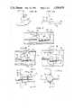
FIG. 1 is a plan view of an improved endocardial electrode provided by the invention;
FIG. 2 is a front view of the electrode tip and tines taken alongline 2--2 of FIG. 1;
FIG. 3 is a plan view of the end portion of the electrode showing the tines and electrode tip;
FIG. 4 is a cross-sectional view taken along line 4--4 of FIG. 3;
FIG. 5 is a cross-sectional view taken along line 5--5 of FIG. 4;
FIG. 6 is a cross-sectional view showing an alternate tine configuration;
FIG. 7 is a plan view of the end portion of the electrode as it is inserted through a vein;
FIG. 8 is a plan view of the end portion of the electrode as it is withdrawn through a vein;
FIG. 9 is a plan view of the end portion of an electrode as it is withdrawn through a vein, the end portion being configured to provide a greater withdrawal resistance than the end portion of FIG. 8;
FIG. 10 is a plan view of the end portion of an electrode showing a further embodiment of the stop means;
FIG. 11 is an end view taken alongline 11--11 of FIG. 10;
FIG. 12 is a plan view showing an alternate embodiment of the invention; and
FIG. 13 is a cross-sectional view of a still further embodiment of an electrode according to the invention.
Detailed illustrative embodiments of the invention disclosed herein exemplify the invention and are currently considered to be the best embodiments for such purposes. They are provided by way of illustration and not limitation of the invention. Various modifications thereof will occur to those skilled in the art, and such modifications are within the scope of the claims which define the present invention.
As previously explained, an improved endocardial electrode is disclosed which incorporates four resilient tines spaced at substantially ninety degree increments around an encased, longitudinally-extending central conductor, the tines extending outwardly from the conductor at substantially ninety degree angles when unrestrained. A stop means in the form of a truncated cone is provided between the extended tines and an electrode tip connected to the conductor end. The stop means is positioned so that only a portion of each tine can bend towards the electrode tip whereas the entire tine can bend away from the electrode tip. This configuration provides different insertion and withdrawal forces for the electrode and also results in a more secure positioning of the electrode tip with respect to an inside surface of a user's heart.
Referring now to FIGS. 1 and 2, an improvedendocardial electrode 10 is shown having an exposedelectrode tip 12 and acentral conductor 14 for conducting electrical pulses from a tissue stimulating device such as a heart pacemaker (not shown) to theelectrode tip 12. An encasingtube 16 formed of a non-conductive material which is substantially inert to body fluids is provided along the length of theconductor 14 for insulating theconductor 14 from the user's body. This insulating material could be either a polyurethane or silicone rubber for example. Fourtines 20 are located near theelectrode tip 12, the tines being formed of a deformable resilient material such as a polyurethane or silicone rubber. Thetines 20 are placed at substantially ninety degree angles about thecentral conductor 14, and when unrestrained extend outwardly from thecentral conductor 14 at substantially ninety degree angles. Although the configuration shown in FIGS. 1 and 2 shows four tines, it should be recognized that any number of tines could be utilized. A restrainingwedge 22 in the form of a truncated cone is located between thetines 20 and theelectrode tip 12 in order to block or stop a portion of thetines 20 from bending towards theelectrode tip 12 while allowing theentire tine 20 to bend away from theelectrode tip 12 as will be explained in further detail below.
Referring now to FIG. 3, thetines 20 and restrainingwedge 22 can be seen in more detail. Thetines 20 are spaced apart from theelectrode tip 12 by a distance D1, D1 generally being less than 1/4 inch. The restrainingwedge 22 is in the shape of a truncated cone having its larger diameter adjacent to thetines 20 and its smaller diameter adjacent to theelectrode tip 12. In the particular embodiment disclosed, the restrainingwedge 22 has a centrally located bore having an inner diameter equal to the outer diameter of the encasingtube 16. This can be seen in the cross-sectional view of FIG. 4. The diameter of the encasingtube 16 is shown as significantly less than that of thewedge 22 for illustrative purposes. In practice, however, the diameter of the encasing tube should be only slightly smaller than that of the restraining wedge.
In assembly, the encasingtube 16 is positioned within the inner bore of the restraining wedge, theelectrode tip 12 then being attached to thecentral conductor 14 and positioned so that it maintains the restrainingwedge 22 in an abutting relationship with respect to thetine surface 23 facing theelectrode tip 12. Alternatively, the restrainingedge 22 could be formed of the same material as the encasingtube 16 and thetines 20, the entire assembly then being molded as one piece.
Other configurations could also be utilized. For example, the entire group oftines 20 could be formed to extend from a cylindrical tube as a separate part which could then be slid over and concentrically positioned with respect to the encasingtube 16, and then fixed in position mechanically, or by gluing adjacent to the restrainingwedge 22, and in an abutting relationship with respect to thetine surface 23 as previously explained. A still further configuration would include thetines 20 andwedge 22 being formed as a separate assembly having a central bore which is adapted to be slidably positioned along the outer surface of the encasingtube 16 and adjacent to theelectrode tip 12.
A further feature of the exemplary embodiment provides for altering the deformation resistance of eachtine 20 as its tip is moved away from theelectrode tip 12 with respect to its deformation resistance as it is moved towards theelectrode tip 12. This is effected by configuring eachtine 20 so that a weakenedportion 24 has a smaller thickness than that of other portions of thetine 20. The weakenedportion 24 is located opposite a blockingsurface 25 formed by the restrainingwedge 22. The blockingsurface 25 is substantially orthogonal to thecentral conductor 14. Referring to FIGS. 3 and 5, one relationship of the weakenedportion 24 of thetine 20 with respect to anon-weakened portion 26 and the restrainingwedge 22 can be seen. It can be appreciated that when atip 32 of thetine 20 is moved toward theelectrode tip 12, thenon-weakened portion 26 of thetine 20 will be deformed. However, when thetine tip 32 is moved away from theelectrode tip 12, less force will be required due to the weakenedportion 24. Thus, more force is required to move thetip 32 towards theelectrode tip 12 than away from theelectrode tip 12. The amount of force required to move thetine tip 32 away from theelectrode tip 12 is related to the thickness of the weakenedportion 24, whereas the force required to move thetip 32 toward theelectrode tip 12 is substantially determined by the thickness of thenon-weakened portion 26 and the height of the blockingsurface 25 with respect to the length of thetine 20 as shown at 28. Both the forward and backward deformation resistances required to move thetine tip 32 can be readily adjusted by choosing the thickness of the weakenedportion 24, thenon-weakened portion 26, and the height of the blockingsurface 25. Thetine 20 could of course have the same thickness along its entire length and still exhibit different deformation resistances as its tip is moved towards and away from theelectrode tip 12.
FIG. 6 shows a tine 26' having a weakened portion 24' proximal to the restraining wedge 22' whereas FIG. 5 shows the weakenedportion 24 distal from the restrainingwedge 22. It should also be noted that the weakend portion need not have a smaller cross-sectional area than the tine itself. For example, it could have an elliptically-shaped cross-sectional area having a minor axis which is perpendicular with respect to the blockingsurface 25. Another technique for creating a weakened portion would be to have small cuts or grooves formed in the tine portion proximal to the central conduction and adjacent to the blocking surface, thereby reducing the flex or deformation resistence when the tine tip is moved backwardly with respect to the electrode tip.
Referring now to FIG. 7, a plan view of thetines 20 andelectrode tip 12 can be seen when positioned within avein 34. When theelectrode tip 12 is being inserted or pushed through thevein 34 in the direction indicated by thearrow 36, thetines 20 andvein 34 will deform to the configuration essentially as shown. As previously explained, the diameter of the weakenedportion 24 basically determines the amount of deformation resistance required to position thetines 20 as shown. However, when theelectrode tip 12 is being withdrawn through thevein 34 in a direction indicated by thearrow 38 shown in FIG. 8, thetines 20 will be positioned essentially as shown. Thus, the amount of deformation resistance required to position thetines 20 away from theelectrode tip 12 is related to the diameter of thenon-weakened portion 26 and the diameter D2 of the blockingsurface 25.
FIG. 9 illustrates that as the diameter D2' of the blocking surface is increased, less of thenon-weakened portion 26 is available for deformation, and the greater the deformation resistance becomes. It can be appreciated that the different forces required for venous insertion and removal of theelectrode tip 12 due to the configuration of thetines 20 and the restrainingwedge 22 as explained above will also result in one force being required for insertion and location of theelectrode tip 12 with respect to the heart trabeculae, and a greater force required to disengage theelectrode tip 12 andtines 20 from the heart trabeculae.
In operation, as thetines 20 are bent away from theelectrode tip 12, the force required to push theelectrode tip 12 into the trabeculae tends to be minimized. However, once positioned, the restrainingwedge 22 tends to restrict forward movement of thetines 20 towards theelectrode tip 12 thereby increasing the force required to disengage theelectrode tip 12 from the trabeculae. As previously explained, selecting the height of the blockingsurface 25 with respect to thetine 20 length, and the diameter of thenon-weakened portion 26, the amount of force required to disengage thetines 20 from the trabeculae can be predetermined while still maintaining the same amount of force required for venous insertion of the electrode as determined by the diameter of the weakenedportion 24. By varying these two parameters during manufacture, a substantially independent means is provided for adjusting the force required to insert the lead with respect to the force required to remove the lead. As soon as theelectrode tip 12 has been moved forward sufficiently so that the end of thetines 20 extend beyond one or more of the trabeculae, they will tend to spring out to their ninety degree undeformed position, thereby tending to hold theelectrode tip 12 in position. Once extended, they will no longer tend to push theelectrode tip 12 out of position, thereby maintaining contact between theelectrode tip 12 and the heart.
Although the exemplary embodiment has utilized a rounded tine and a truncated cone for the restrainingwedge 22, it should be recognized that other stop means and tine configurations could be utilized. For example, an alternate configuration of the stop means can be seen in FIGS. 10 and 11. Tines 20', encasing tube 16', and electrode tip 12' are provided as in the preceding embodiment. However, instead of the conically-shapedrestraining wedge 22 shown in FIG. 3, four upwardly protruding restrainingwedges 40 are utilized. Each of the restrainingwedges 40 are positioned between a tine 20' and the electrode tip 12' so that a restrainingwedge blocking surface 42 is positioned directly between its corresponding tine 20' and the electrode tip 12'. One advantage of this embodiment is that the tines 20' and restrainingwedges 40 can be formed as one piece and then separated along blockingsurface 42 by an appropriate cutting tool. It should be noted that the withdrawal force can also be decreased by spacing apart the blockingsurface 42 from the tine 20', thereby allowing some deformation of the entire tine 20' to occur before it abuts against the blockingsurface 42.
A further embodiment of the invention can be seen in FIG. 12. Here, atine 50 protrudes from the encasingmaterial 52. Anelectrode tip 54 is attached to a central electrical conductor (not shown) which is centrally positioned in the encasingmaterial 52. Aslit 56 is formed in the encasing material beginning at the tine/encasing material interface point that is proximal to saidelectrode tip 54. Theslit 56 forms an acute angle A with respect to a line 60 which extends from theelectrode tip 54 along the longitudinal axis of the central conductor. It should be noted that the embodiment of FIG. 12 shows theslit 56 forming an acute angle A with respect to the line 60. However, angle A need not necessarily be acute but rather need only be such that the effective cross-sectional thickness of the tine is reduced as it is folded back and away from theelectrode tip 54 with respect to the effective cross-sectional thickness as it is moved towards theelectrode tip 54.
A further embodiment of the invention is shown in FIG. 13. Here, nonconducting encasing material 70 surrounds acentral conductor 72 which is attached to anelectrode tip 74.Tines 76 are formed at the end of the encasing material 70 and located so that one surface abuts against theinner surface 78 of theelectrode tip 74. A weakenedportion 80 similar to that shown in FIG. 3 embodiment is also provided. In operation, thetine 76 abuts against theelectrode surface 78 when its tip is moved towards theelectrode tip 74, thus creating a first deformation resistance. A second deformation resistance lower than the first deformation resistence is provided when the tine tip is moved away from theelectrode tip 74, this lower resistence being partially due to the weakenedportion 80.
Claims (23)
1. In an endocardial electrode of the type having an electrical conductor encased in an encasing material which is generally inert to body fluids, the conductor terminating at an exposed electrically conductive electrode tip, the improvement comprising:
resilient tine means near the electrode tip comprising at least one tine for cooperating with heart tissue and holding the electrode tip in position, said tine exhibiting a first deformation resistance when said tine tip is moved away from the electrode tip, and
means for blocking the movement of a portion of said tine as said tine tip is moved towards the electrode tip, thereby providing a second deformation resistance which is greater than said first deformation resistance.
2. The improvement of claim 1 wherein said tine when unrestrained forms a substantially ninety degree angle with respect to the electrical conductor.
3. The improvement of claim 1 or 2 wherein said means for blocking comprises stop means for abutting against a portion of said tine surface facing the electrode tip, thereby increasing the deformation resistance when said tine tip is moved towards the electrode tip.
4. The improvement of claim 3 wherein said stop means defines a surface substantially orthogonal to, and symetrical about, the electrical conductor, said surface extending from the encasing material to a predetermined distance from said tine tip.
5. The improvement of claim 4 wherein said stop means is formed as a truncated cone symetrically positioned about the electrical conductor, said cone being formed of a nonconductive material which is generally inert to body fluids.
6. The improvement of claim 5 wherein said cone surface tapers towards the electrode tip.
7. The improvement of claim 4 wherein said stop means is defined by a portion of the electrode tip.
8. The improvement of claim 3 wherein said tine is configured to have a weakened portion proximal to the base of said tine.
9. The imporvement of claim 8 wherein said weakened portion has a smaller thickness than another portion of said tine distal from said tine base.
10. The improvement of claim 9 wherein said smaller cross-sectional area is offset with respect to the center-line of said tine.
11. The improvement of claim 3 wherein said stop means comprises a wedge-shaped protrusion extending from the encasing material and defining a surface extending from the encasing material to a predetermined distance from said tine tip.
12. The improvement of claim 11 wherein said surface defined by said stop means is substantially orthogonal to the electrical conductor.
13. The improvement of claim 1 wherein said tine means comprises four tines.
14. In an endocardial electrode of the type having an electrical conductor encased in an encasing material which is generally inert to body fluids, the conductor terminating at an exposed electrically conductive electrode tip, the improvement comprising:
resilient tine means near the electrode tip comprising at least one tine for cooperating with heart tissue and holding the electrode tip is position, said tine exhibiting a first deformation resistance when said tine tip is moved away from the electrode tip; and
means for providing a second deformation resistance when said tine tip is moved towards the electrode tip, said means for providing comprising said encasing material being formed to define a slit extending downwardly into said encasing material adjacent to the location where said tine intersects said encasing material.
15. The improvement of claim 14 wherein said location at which said tine intersects said encasing material is proximal to said electrode tip, said slit surfaces forming an acute angle with respect to a line extending between said electrode tip and said tine along the longitudinal axis of said electrical conductor.
16. In an endocardial electrode of the type having an electrical conductor encased in an encasing material which is generally inert to body fluids, the conductor terminating at an exposed electrically conductive electrode tip, the improvement comprising:
tine means near the electrode tip and comprising at least one tine for cooperating with heart tissue and holding the electrode tip in position, said tine when unrestrained forming a substantially ninety degree angle with respect to the electrical conductor and being of a pliant material having sufficient rigidity to maintain said ninety degree angle when unrestrained, but sufficiently pliant to prevent penetration of said heart tissue, said pliant material being generally inert to body fluids, said tine exhibiting a first deformation resistance when its tip is moved away from the electrode tip; and
means for providing a second deformation resistance greater than said first deformation resistance when said tine tip is moved towards the electrode tip.
17. The improvement of claim 16 wherein said means for providing comprises stop means for allowing only a first predetermined portion of said tine including said tine tip to bend towards the electrode tip.
18. The improvement of claim 17 wherein the cross-sectional area of a portion of said tine within said first predetermined portion is greater than the cross-sectional area of a portion of said tine not within said first predetermined portion.
19. The improvement of claim 17 wherein said stop means defines a surface adjacent to said tine for allowing only said first predetermined portion to bend towards the electrode tip.
20. The improvement of claim 17 wherein said stop means comprises a portion of the electrode tip.
21. The improvement of claim 17 wherein said stop means comprises a wedge-shaped protrusion extending outwardly from the encasing material and defining a surface substantially orthogonal to the electrical conductor, said surface being adjacent to a portion of said tine facing the electrode tip and extending to a predetermined distance from said tine tip.
22. The improvement of claim 16 wherein said means for providing said second deformation resistance comprises said encasing materials being formed to define a slit which intersects said encasing material, said slit extending downwardly into said encasing material and being located so as to create a greater resistance to bending of the tine in the direction of the electrode tip than away from the electrode tip.
23. The improvement of claim 22 wherein a point at which said tine intersects said encasing material is proximal to said electrode tip, said slit surfaces forming an acute angle with respect to a line extending from said electrode tip along the longitudinal axis of said electrical conductor.
Priority Applications (1)
| Application Number | Priority Date | Filing Date | Title |
|---|---|---|---|
| US06/430,912US4506679A (en) | 1982-09-30 | 1982-09-30 | Endocardial electrode |
Applications Claiming Priority (1)
| Application Number | Priority Date | Filing Date | Title |
|---|---|---|---|
| US06/430,912US4506679A (en) | 1982-09-30 | 1982-09-30 | Endocardial electrode |
Publications (1)
| Publication Number | Publication Date |
|---|---|
| US4506679Atrue US4506679A (en) | 1985-03-26 |
Family
ID=23709612
Family Applications (1)
| Application Number | Title | Priority Date | Filing Date |
|---|---|---|---|
| US06/430,912Expired - LifetimeUS4506679A (en) | 1982-09-30 | 1982-09-30 | Endocardial electrode |
Country Status (1)
| Country | Link |
|---|---|
| US (1) | US4506679A (en) |
Cited By (26)
| Publication number | Priority date | Publication date | Assignee | Title |
|---|---|---|---|---|
| US4641664A (en)* | 1984-04-13 | 1987-02-10 | Siemens Aktiengesellschaft | Endocardial electrode arrangement |
| US4669488A (en)* | 1983-03-28 | 1987-06-02 | Cordis Corporation | Retention skirt for pacing electrode assembly |
| US4716888A (en)* | 1985-06-17 | 1988-01-05 | Cordis Corporation | Tined leads |
| US4722353A (en)* | 1985-09-16 | 1988-02-02 | Intermedics, Inc. | Stabilizer for implantable electrode |
| US4913164A (en)* | 1988-09-27 | 1990-04-03 | Intermedics, Inc. | Extensible passive fixation mechanism for lead assembly of an implantable cardiac stimulator |
| US5203345A (en)* | 1991-10-31 | 1993-04-20 | University Of Manitoba | Method of using a support anchor for the vagina of a mammalian female |
| US5807399A (en)* | 1996-10-23 | 1998-09-15 | Medtronic, Inc. | Method for removal of chronically implanted leads and leads optimized for use therewith |
| US6181973B1 (en) | 1999-04-02 | 2001-01-30 | Claudio Ceron | Anchoring structure for implantable electrodes |
| US6611721B1 (en) | 1999-06-25 | 2003-08-26 | Biotronik Mess-Und Therapiegeraete Gmbh & Co. Ingenieurbuero Berlin | Break-away extractable lead |
| US20050060014A1 (en)* | 2001-08-31 | 2005-03-17 | Medtronic, Inc. | Implantable medical electrical stimulation lead fixation method and apparatus |
| US20050251237A1 (en)* | 2004-05-10 | 2005-11-10 | Advanced Bionics Corporation | Implantable electrode, insertion tool for use therewith, and insertion method |
| US20070100411A1 (en)* | 2005-10-27 | 2007-05-03 | Medtronic, Inc. | Implantable medical electrical stimulation lead fixation method and apparatus |
| WO2008140365A1 (en)* | 2007-05-15 | 2008-11-20 | St. Jude Medical Ab | Medical implantable lead with pivoting segments |
| US20150133955A1 (en)* | 2012-04-19 | 2015-05-14 | Medtronic, Inc. | Medical leads having a distal body and an openly coiled filar |
| US10434329B2 (en) | 2014-05-09 | 2019-10-08 | The Board Of Trustees Of The Leland Stanford Junior University | Autofocus wireless power transfer to implantable devices in freely moving animals |
| US10485969B2 (en) | 2016-02-19 | 2019-11-26 | Boston Scientific Neuromodulation Corporation | Electrical stimulation cuff devices and systems |
| US10493269B2 (en) | 2016-06-02 | 2019-12-03 | Boston Scientific Neuromodulation Corporation | Leads for electrostimulation of peripheral nerves and other targets |
| US10709888B2 (en) | 2016-07-29 | 2020-07-14 | Boston Scientific Neuromodulation Corporation | Systems and methods for making and using an electrical stimulation system for peripheral nerve stimulation |
| US10814127B2 (en) | 2016-02-05 | 2020-10-27 | Boston Scientific Neuromodulation Corporation | Slotted sleeve neurostimulation device |
| US10828502B2 (en) | 2014-03-03 | 2020-11-10 | The Board Of Trustees Of The Leland Stanford Junior University | Methods and apparatus for power conversion and data transmission in implantable sensors, stimulators, and actuators |
| US10905883B2 (en) | 2016-12-02 | 2021-02-02 | Boston Scientific Neuromodulation Corporation | Methods and systems for selecting stimulation parameters for electrical stimulation devices |
| US11097096B2 (en) | 2017-05-09 | 2021-08-24 | Nalu Medical, Inc. | Stimulation apparatus |
| US11160980B2 (en) | 2017-02-24 | 2021-11-02 | Nalu Medical, Inc. | Apparatus with sequentially implanted stimulators |
| US11766561B2 (en) | 2016-07-18 | 2023-09-26 | Nalu Medical, Inc. | Methods and systems for treating pelvic disorders and pain conditions |
| US11938327B2 (en) | 2016-03-21 | 2024-03-26 | Nalu Medical, Inc. | Devices and methods for positioning external devices in relation to implanted devices |
| US12194291B2 (en) | 2021-05-21 | 2025-01-14 | Boston Scientific Neuromodulation Corporation | Electrical stimulation cuff devices and systems with helical arrangement of electrodes |
Citations (3)
| Publication number | Priority date | Publication date | Assignee | Title |
|---|---|---|---|---|
| US4236529A (en)* | 1979-02-21 | 1980-12-02 | Daig Corporation | Tined lead |
| US4269198A (en)* | 1979-12-26 | 1981-05-26 | Medtronic, Inc. | Body implantable lead |
| US4301815A (en)* | 1980-01-23 | 1981-11-24 | Telectronics Pty. Limited | Trailing tine electrode lead |
- 1982
- 1982-09-30USUS06/430,912patent/US4506679A/ennot_activeExpired - Lifetime
Patent Citations (3)
| Publication number | Priority date | Publication date | Assignee | Title |
|---|---|---|---|---|
| US4236529A (en)* | 1979-02-21 | 1980-12-02 | Daig Corporation | Tined lead |
| US4269198A (en)* | 1979-12-26 | 1981-05-26 | Medtronic, Inc. | Body implantable lead |
| US4301815A (en)* | 1980-01-23 | 1981-11-24 | Telectronics Pty. Limited | Trailing tine electrode lead |
Cited By (43)
| Publication number | Priority date | Publication date | Assignee | Title |
|---|---|---|---|---|
| US4669488A (en)* | 1983-03-28 | 1987-06-02 | Cordis Corporation | Retention skirt for pacing electrode assembly |
| US4641664A (en)* | 1984-04-13 | 1987-02-10 | Siemens Aktiengesellschaft | Endocardial electrode arrangement |
| US4716888A (en)* | 1985-06-17 | 1988-01-05 | Cordis Corporation | Tined leads |
| US4722353A (en)* | 1985-09-16 | 1988-02-02 | Intermedics, Inc. | Stabilizer for implantable electrode |
| US4913164A (en)* | 1988-09-27 | 1990-04-03 | Intermedics, Inc. | Extensible passive fixation mechanism for lead assembly of an implantable cardiac stimulator |
| US5203345A (en)* | 1991-10-31 | 1993-04-20 | University Of Manitoba | Method of using a support anchor for the vagina of a mammalian female |
| US5807399A (en)* | 1996-10-23 | 1998-09-15 | Medtronic, Inc. | Method for removal of chronically implanted leads and leads optimized for use therewith |
| US6181973B1 (en) | 1999-04-02 | 2001-01-30 | Claudio Ceron | Anchoring structure for implantable electrodes |
| US6611721B1 (en) | 1999-06-25 | 2003-08-26 | Biotronik Mess-Und Therapiegeraete Gmbh & Co. Ingenieurbuero Berlin | Break-away extractable lead |
| US20050060014A1 (en)* | 2001-08-31 | 2005-03-17 | Medtronic, Inc. | Implantable medical electrical stimulation lead fixation method and apparatus |
| US7912555B2 (en) | 2001-08-31 | 2011-03-22 | Medtronic, Inc. | Implantable medical electrical stimulation lead fixation method and apparatus |
| US6999819B2 (en) | 2001-08-31 | 2006-02-14 | Medtronic, Inc. | Implantable medical electrical stimulation lead fixation method and apparatus |
| US20060129218A1 (en)* | 2001-08-31 | 2006-06-15 | Medtronic, Inc. | Implantable medical electrical stimulation lead fixation method and apparatus |
| US20070050004A1 (en)* | 2001-08-31 | 2007-03-01 | Medtronic, Inc. | Implantable medical lead including tine markers |
| US8626314B2 (en) | 2001-08-31 | 2014-01-07 | Medtronic, Inc. | Implantable medical lead including a plurality of tine elements |
| US7330764B2 (en) | 2001-08-31 | 2008-02-12 | Medtronic, Inc. | Implantable medical electrical stimulation lead fixation method and apparatus |
| US8036756B2 (en) | 2001-08-31 | 2011-10-11 | Medtronics Inc | Implantable medical electrical stimulation lead fixation method and apparatus |
| US8000805B2 (en) | 2001-08-31 | 2011-08-16 | Medtronic, Inc. | Implantable medical lead including tine markers |
| US20050251237A1 (en)* | 2004-05-10 | 2005-11-10 | Advanced Bionics Corporation | Implantable electrode, insertion tool for use therewith, and insertion method |
| US8538554B2 (en) | 2004-05-10 | 2013-09-17 | Boston Scientific Neuromodulation Corporation | Implantable electrode, insertion tool for use therewith, and insertion method |
| US20090024196A1 (en)* | 2004-05-10 | 2009-01-22 | Boston Scientific Neuromodulation Corporation | Implantable electrode, insertion tool for use therewith, and insertion method |
| US7460913B2 (en)* | 2004-05-10 | 2008-12-02 | Boston Scientific Neuromodulation Corporation | Implantable electrode, insertion tool for use therewith, and insertion method |
| US20070100411A1 (en)* | 2005-10-27 | 2007-05-03 | Medtronic, Inc. | Implantable medical electrical stimulation lead fixation method and apparatus |
| US20100324636A1 (en)* | 2007-05-15 | 2010-12-23 | Rolf Hill | MEDICAL IMPLANTABLE LEAD WITH PIVOTING SEGMENTS (As Amended) |
| WO2008140365A1 (en)* | 2007-05-15 | 2008-11-20 | St. Jude Medical Ab | Medical implantable lead with pivoting segments |
| US20150133955A1 (en)* | 2012-04-19 | 2015-05-14 | Medtronic, Inc. | Medical leads having a distal body and an openly coiled filar |
| US10086191B2 (en)* | 2012-04-19 | 2018-10-02 | Medtronic, Inc. | Medical leads having a distal body and an openly coiled filar |
| US20190022374A1 (en)* | 2012-04-19 | 2019-01-24 | Medtronic, Inc. | Medical leads having a distal body and an openly coiled filar |
| US11013915B2 (en)* | 2012-04-19 | 2021-05-25 | Medtronic, Inc. | Medical leads having a distal body and an openly coiled filar |
| US10828502B2 (en) | 2014-03-03 | 2020-11-10 | The Board Of Trustees Of The Leland Stanford Junior University | Methods and apparatus for power conversion and data transmission in implantable sensors, stimulators, and actuators |
| US10434329B2 (en) | 2014-05-09 | 2019-10-08 | The Board Of Trustees Of The Leland Stanford Junior University | Autofocus wireless power transfer to implantable devices in freely moving animals |
| US10814127B2 (en) | 2016-02-05 | 2020-10-27 | Boston Scientific Neuromodulation Corporation | Slotted sleeve neurostimulation device |
| US10485969B2 (en) | 2016-02-19 | 2019-11-26 | Boston Scientific Neuromodulation Corporation | Electrical stimulation cuff devices and systems |
| US11938327B2 (en) | 2016-03-21 | 2024-03-26 | Nalu Medical, Inc. | Devices and methods for positioning external devices in relation to implanted devices |
| US10493269B2 (en) | 2016-06-02 | 2019-12-03 | Boston Scientific Neuromodulation Corporation | Leads for electrostimulation of peripheral nerves and other targets |
| US11766561B2 (en) | 2016-07-18 | 2023-09-26 | Nalu Medical, Inc. | Methods and systems for treating pelvic disorders and pain conditions |
| US10709888B2 (en) | 2016-07-29 | 2020-07-14 | Boston Scientific Neuromodulation Corporation | Systems and methods for making and using an electrical stimulation system for peripheral nerve stimulation |
| US10905883B2 (en) | 2016-12-02 | 2021-02-02 | Boston Scientific Neuromodulation Corporation | Methods and systems for selecting stimulation parameters for electrical stimulation devices |
| US11160980B2 (en) | 2017-02-24 | 2021-11-02 | Nalu Medical, Inc. | Apparatus with sequentially implanted stimulators |
| US11826569B2 (en) | 2017-02-24 | 2023-11-28 | Nalu Medical, Inc. | Apparatus with sequentially implanted stimulators |
| US11097096B2 (en) | 2017-05-09 | 2021-08-24 | Nalu Medical, Inc. | Stimulation apparatus |
| US12201829B2 (en) | 2017-05-09 | 2025-01-21 | Nalu Medical, Inc. | Stimulation apparatus |
| US12194291B2 (en) | 2021-05-21 | 2025-01-14 | Boston Scientific Neuromodulation Corporation | Electrical stimulation cuff devices and systems with helical arrangement of electrodes |
Similar Documents
| Publication | Publication Date | Title |
|---|---|---|
| US4506679A (en) | Endocardial electrode | |
| US4641664A (en) | Endocardial electrode arrangement | |
| US4716888A (en) | Tined leads | |
| EP0387551B1 (en) | Pacing lead | |
| US4209019A (en) | Stylet insertion guide and rotation control device for use with body implantable lead | |
| US4233992A (en) | Implantable electrode | |
| US4236529A (en) | Tined lead | |
| US5645580A (en) | Implantable medical device lead assembly having high efficiency, flexible electrode head | |
| US4285347A (en) | Stabilized directional neural electrode lead | |
| US4407303A (en) | Endocardial electrode arrangement | |
| US4791939A (en) | Stylet for use with an implantable pacing lead | |
| EP0610301B1 (en) | Improved electrode assembly for nerve stimulation | |
| EP0709111B1 (en) | Medical electrical lead system having a torque transfer stylet | |
| CA1082317A (en) | Body implantable lead with stiffening stylet | |
| CA2409111C (en) | Lead removal apparatus | |
| US4280512A (en) | Cardiac pacemaker electrode for transvenous application | |
| EP0085417B1 (en) | Biomedical stimulation lead | |
| US4280510A (en) | Sutureless myocardial lead introducer | |
| CA1085932A (en) | Body-implantable lead | |
| JP2896179B2 (en) | Intravascular electrode lead usable for defibrillation of the heart | |
| GB2067411A (en) | Electrode lead | |
| NL8020222A (en) | ENDOCARDIAL, IMPLANTABLE PIPE FOR A HEART STIMULATOR. | |
| EP0861676A3 (en) | Electrode array catheter | |
| US4841971A (en) | Endocardial lead with projections having saw tooth formation | |
| GB1584093A (en) | Medical electrode and lead assembly |
Legal Events
| Date | Code | Title | Description |
|---|---|---|---|
| AS | Assignment | Owner name:PACESETTER SYSTEMS, INC., 12884 BRADLEY AVE., SYLM Free format text:ASSIGNMENT OF ASSIGNORS INTEREST.;ASSIGNOR:MANN, ALFRED E.;REEL/FRAME:004055/0313 Effective date:19820929 | |
| STCF | Information on status: patent grant | Free format text:PATENTED CASE | |
| AS | Assignment | Owner name:SIEMENS-ELEMA AB, A CORP OF SWEDEN Free format text:ASSIGNMENT OF ASSIGNORS INTEREST.;ASSIGNOR:PACESETTER SYSTEMS, INC., A CORP OF CA.;REEL/FRAME:004559/0175 Effective date:19850430 | |
| FEPP | Fee payment procedure | Free format text:PAYOR NUMBER ASSIGNED (ORIGINAL EVENT CODE: ASPN); ENTITY STATUS OF PATENT OWNER: LARGE ENTITY | |
| FPAY | Fee payment | Year of fee payment:4 | |
| FPAY | Fee payment | Year of fee payment:8 | |
| AS | Assignment | Owner name:PACESETTER AB, SWEDEN Free format text:ASSIGNMENT OF ASSIGNORS INTEREST;ASSIGNOR:AB, SIEMENS-ELEMA;REEL/FRAME:007297/0115 Effective date:19940924 | |
| FPAY | Fee payment | Year of fee payment:12 |