US4506667A - Self-contained ventilator/resuscitator - Google Patents
Self-contained ventilator/resuscitatorDownload PDFInfo
- Publication number
- US4506667A US4506667AUS06/482,621US48262183AUS4506667AUS 4506667 AUS4506667 AUS 4506667AUS 48262183 AUS48262183 AUS 48262183AUS 4506667 AUS4506667 AUS 4506667A
- Authority
- US
- United States
- Prior art keywords
- accumulator
- housing
- patient
- filter
- resuscitator
- Prior art date
- Legal status (The legal status is an assumption and is not a legal conclusion. Google has not performed a legal analysis and makes no representation as to the accuracy of the status listed.)
- Expired - Lifetime
Links
- 210000004072lungAnatomy0.000claimsabstractdescription10
- QVGXLLKOCUKJST-UHFFFAOYSA-Natomic oxygenChemical compound[O]QVGXLLKOCUKJST-UHFFFAOYSA-N0.000claimsdescription33
- 239000001301oxygenSubstances0.000claimsdescription33
- 229910052760oxygenInorganic materials0.000claimsdescription33
- 230000003434inspiratory effectEffects0.000claimsdescription23
- 239000003570airSubstances0.000claimsdescription21
- 239000012080ambient airSubstances0.000claimsdescription9
- 230000000241respiratory effectEffects0.000claimsdescription9
- 239000012530fluidSubstances0.000claims1
- 239000007789gasSubstances0.000abstractdescription41
- XTEGARKTQYYJKE-UHFFFAOYSA-MChlorateChemical compound[O-]Cl(=O)=OXTEGARKTQYYJKE-UHFFFAOYSA-M0.000abstractdescription18
- 230000029058respiratory gaseous exchangeEffects0.000description16
- 239000000463materialSubstances0.000description3
- 210000002445nippleAnatomy0.000description3
- OKTJSMMVPCPJKN-UHFFFAOYSA-NCarbonChemical compound[C]OKTJSMMVPCPJKN-UHFFFAOYSA-N0.000description2
- 238000001914filtrationMethods0.000description2
- 239000000203mixtureSubstances0.000description2
- 206010003497AsphyxiaDiseases0.000description1
- 230000000903blocking effectEffects0.000description1
- 239000000356contaminantSubstances0.000description1
- 238000007599dischargingMethods0.000description1
- 230000000977initiatory effectEffects0.000description1
- 239000003958nerve gasSubstances0.000description1
- 230000001105regulatory effectEffects0.000description1
- 230000002269spontaneous effectEffects0.000description1
- 239000013589supplementSubstances0.000description1
- 230000001502supplementing effectEffects0.000description1
- 231100000331toxicToxicity0.000description1
- 230000002588toxic effectEffects0.000description1
- 238000003466weldingMethods0.000description1
Images
Classifications
- A—HUMAN NECESSITIES
- A61—MEDICAL OR VETERINARY SCIENCE; HYGIENE
- A61M—DEVICES FOR INTRODUCING MEDIA INTO, OR ONTO, THE BODY; DEVICES FOR TRANSDUCING BODY MEDIA OR FOR TAKING MEDIA FROM THE BODY; DEVICES FOR PRODUCING OR ENDING SLEEP OR STUPOR
- A61M16/00—Devices for influencing the respiratory system of patients by gas treatment, e.g. ventilators; Tracheal tubes
- A61M16/10—Preparation of respiratory gases or vapours
- A61M16/12—Preparation of respiratory gases or vapours by mixing different gases
- A61M16/122—Preparation of respiratory gases or vapours by mixing different gases with dilution
- A61M16/125—Diluting primary gas with ambient air
- A61M16/127—Diluting primary gas with ambient air by Venturi effect, i.e. entrainment mixers
- A—HUMAN NECESSITIES
- A61—MEDICAL OR VETERINARY SCIENCE; HYGIENE
- A61M—DEVICES FOR INTRODUCING MEDIA INTO, OR ONTO, THE BODY; DEVICES FOR TRANSDUCING BODY MEDIA OR FOR TAKING MEDIA FROM THE BODY; DEVICES FOR PRODUCING OR ENDING SLEEP OR STUPOR
- A61M16/00—Devices for influencing the respiratory system of patients by gas treatment, e.g. ventilators; Tracheal tubes
- A61M16/021—Devices for influencing the respiratory system of patients by gas treatment, e.g. ventilators; Tracheal tubes operated by electrical means
- A61M16/022—Control means therefor
- A—HUMAN NECESSITIES
- A61—MEDICAL OR VETERINARY SCIENCE; HYGIENE
- A61M—DEVICES FOR INTRODUCING MEDIA INTO, OR ONTO, THE BODY; DEVICES FOR TRANSDUCING BODY MEDIA OR FOR TAKING MEDIA FROM THE BODY; DEVICES FOR PRODUCING OR ENDING SLEEP OR STUPOR
- A61M16/00—Devices for influencing the respiratory system of patients by gas treatment, e.g. ventilators; Tracheal tubes
- A61M16/10—Preparation of respiratory gases or vapours
- A61M16/105—Filters
- A61M16/106—Filters in a path
- A61M16/107—Filters in a path in the inspiratory path
- A—HUMAN NECESSITIES
- A61—MEDICAL OR VETERINARY SCIENCE; HYGIENE
- A61M—DEVICES FOR INTRODUCING MEDIA INTO, OR ONTO, THE BODY; DEVICES FOR TRANSDUCING BODY MEDIA OR FOR TAKING MEDIA FROM THE BODY; DEVICES FOR PRODUCING OR ENDING SLEEP OR STUPOR
- A61M16/00—Devices for influencing the respiratory system of patients by gas treatment, e.g. ventilators; Tracheal tubes
- A61M16/0057—Pumps therefor
- A61M16/0075—Bellows-type
Definitions
- the present inventionrelates generally to a respiratory device, and more particularly to a self-contained portable ventilator/resuscitator provided with an internal power supply and power operated pump and control means which, in normal operation operates cyclically to force filtered air and oxygen into the lungs of the patient and then to permit the patient's respiratory cavity to expire, said ventilator/resuscitator also capable of being operated manually if the power supply should fail.
- Various types of respiratory devicesare well known in the art, and the present invention deals with that class of devices generally referred to as either resuscitators and/or ventilators, depending upon the primary intended usage.
- One prior art deviceis a "Bear II Ventilator".
- the ventilatorforces a tidal volume of an air oxygen mixture into a patient's lungs for a prescribed period of time, for example two seconds, and then permits the patient's respiratory cavity to collapse thereby expelling the air oxygen mixture for another prescribed period of time, for example four seconds.
- This same ventilatormay also be operated in another mode wherein, in addition to operating in a timed cycle, it would also sense through pressure changes spontaneous inspiratory effort by the patient, which sensed changes would cause the ventilator to switch from expiratory mode to an inspiratory mode.
- electronic circuitrycould cause the device to shift into its inspiratory mode.
- a lightweight portable ventilator/resuscitatorbe developed which is capable of utilizing filtered ambient gases, to supplement an internal source of pressurized breathing gases, the ambient gases passing through a filter to remove toxic or harmful contaminants.
- a portable ventilator/resuscitatorshould initially operate from an internal power supply, such as the source of pressurized breathing gases (which may be an oxygen generator or a container of compressed gas), but it is desirable that upon failure of the internal power supply that it can also be operated in a manual mode.
- a self-contained portable ventilator/resuscitator of the typehaving a filter capable of filtering ambient gases, pump means normally operable to cause ambient gases to be drawn through said filter, control means capable of either directing the output of the pump to an outlet to a patient during an inspiratory mode of operation, or directing the output of the pump to an accumulator during an expiratory mode, and means capable of manually expanding and retracting the accumulator and operable, when the pump fails to operate normally, to draw ambient gases through the filter and into the accumulator when the accumulator is being manually expanded, and to force the filtered gases into the patient when the accumulator is being manually retracted.
- a source of pressurized breathing gassuch as oxygen
- a self-contained portable ventilator/resuscitator assemblyincluding a housing which receives side by side cylindrical members, one of which contains a source of pressurized breathing gases, and the other being a filter having an inlet end open to ambient gases.
- the housingfurther contains a jet pump, the nozzle of which is connected to the source of pressurized breathing gases, and the suction side of the jet pump being connected to the outlet end of the filter.
- the housingis also provided with control means which may include fluidic elements, air logic elements, or both, the operation of which is preferably powered by the source of pressurized breathing gases.
- a bellows-type accumulatorhaving a rigid end wall spaced away from the housing, a handle in the form of a bent outlet pipe being secured to the end wall, and the bent outlet pipe also being connected to an extensible and retractable outlet connection disposed within the accumulator.
- pressurized breathing gasesare mixed with filtered ambient gases within the pump, the mixed gases being cyclically directed either to the patient or to the accumulator during inspiratory and expiratory modes, respectively.
- the accumulatorcan be manually operated to either draw filtered ambient gases into the accumulator as the accumulator is expanded, or alternatively to force filtered ambient air into the lungs of the patient as the accumulator is retracted.
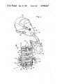
- FIG. 1is an overall view of the self-contained portable ventilator/resuscitator of this invention.
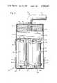
- FIG. 2is a sectional view taken generally along the line 2--2 in FIG. 1 showing further details of various elements of the ventilator/resuscitator.
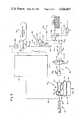
- FIG. 3is a schematic illustration of various operational components of the ventilator/resuscitator.
- the ventilator/resuscitator of the present inventionin indicated generally at 10 in FIGS. 1 and 2 and includes a relatively rigid case or housing 12 within which various of the operational components of the ventilator/resuscitator may be housed. Mounted on one end of the housing 12 is a bellows-type accumulator 14. Passing through the accumulator 14 is an outlet indicated generally at 16.
- the ventilator/resuscitatoris also provided with a mask, harness, and suitable tubing, for interconnecting the outlet 16 with the patient.
- a mask, harness, and suitable tubingfor interconnecting the outlet 16 with the patient.
- flexible tubing 18is secured at one end to the outlet 16 and is secured at the other end to a mask 20.
- the mask 20is adapted to be held over the nose and mouth of a patient by means of a harness 22 and adjustable straps 24.
- the mask 20may be provided with an inhalation/exhalation valve assembly indicated generally at 26 and an anti-suffocation valve indicated at 28.
- a filter indicated generally at 30mounted within the housing 12 is a filter indicated generally at 30, pump means indicated generally at 32, control means indicated generally at 34, and a source of pressurized breathing gas indicated generally at 36.
- the filter 30includes a generally cylindrical container 38 in which suitable filtering material, such as activated charcoal, is mounted. As viewed in FIG. 2 the upper end wall of the generally cylindrical filter is the outlet and the lower end wall 40 is the inlet.
- suitable filtering materialsuch as activated charcoal
- the pump 32Disposed immediately above the outlet end of the filter 30 and below the controls 34 is the pump 32.
- the pumpis in the form of a jet pump, the jet pump including a nozzle 42 (best shown in FIG. 3.), a body 44 including a diffuser 46, a suction portion 48, and a discharge portion 50.
- the suction portion 48includes a cylindrical part 52 which can receive the upper end of the container 38 in a gas tight relationship.
- the various parts of the pump 32are secured to the housing 12 in a manner not material to the present invention.
- the source of pressurized breathing gas 36could be a container of oxygen under pressure, it is preferably in the form of a chlorate candle.
- a chlorate candleis customarily provided with a discharge opening 54 which can in turn be interconnected with tubing means 56 which in this case would be interconnected with the nozzle 42 of the jet pump.
- the operation of the chlorate candleis initiated by a primer indicated at 58, the operation of which is in turn initiated by pulling pin 60 by means of a lanyard 62. Once the operation of the candle has been initiated it will burn, forcing oxygen through a filter bed 64 and through the discharge opening 54 and on to the jet pump.
- the chlorate candle 36is in the form of a cylindrical element.
- the housing 12is provided with a removable bottom element 66, which element is relatively rigid and provided with screened apertures 68 in its bottom.
- the bottom elementis secured in place by straps 70 and fasteners 72.
- the housingis provided with depending support elements 74 which are adapted to contact the top of the candle 36 to limit its upper movement and in a similar manner the cylindrical part 52 limits the upward movement of the filter 30.
- the filter 30 and the candle 36are held against the support elements 74 and the cylindrical part 52 by means of abutments 76 carried by the bottom element 66.
- clothes clips 78are provided, which clothes clips are secured to the housing 12 by means of flexible straps 80, and which can in turn be secured to the clothing (illustrated in part at 82) of a patient.
- the accumulator 14is of a bellows type and is provided with a pleated or convoluted sidewall of flexible impervious material, which sidewall is normally spring biased to its normal retracted position by an internal spring 86. (In the alternative, this could be accomplished by the set of the pleated sidewall itself.)
- One end of the accumulatoris provided with a rigid end wall 88 which is spaced away from the housing 12. This end wall can be moved towards or away from the housing by manual operation and to this end the outlet 16 includes a right angle tube 90 and nipple 91 which are rigidly secured to each other and to the end wall 38 by welding or the like.
- this tubeserves as a handle which can be engaged manually to pull the end plate away from the housing 12 to expand the accumulator, or, in the alternative, it can be forced towards the housing 12 to retract the accumulator.
- the nipple 91is further operatively connected to an extensible and retractable tube 92 disposed within the accumulator, the last mentioned tube also forming part of the outlet to the patient. Before use, the accumulator is held in its retracted position by strap and fastener 93.
- control means 34is contained within the canister housing 12 at the upper end thereof.
- control means 34may include elements external of the housing 12, such as the outlet 16, flexible tubing 18, and the inhalation/exhalation valve assembly 26 which has been previously referred to.
- the inhalation/exhalation valve 26 assemblymay be of the type shown in U.S. Pat. No. 3,342,200, or alternatively, it may be formed of separate components as indicated in FIG. 3. While the form generally shown in U.S. Pat. No. 3,342,200 is preferred, it will be described as separate components for the sake of convenience to the understanding of the nature of this invention.
- the control means 34includes a primary control unit indicated generally at 94, which control unit is capable of directing the output of the pump to the patient during a timed inspiratory phase, or to the accumulator during a timed expiratory phase, which primary control unit is also pressure responsive to either inspiratory or expiratory effort on the part of the patient to override the timed functions.
- a primary control unitmay be of the type shown in applicant's copending U.S. application Ser. No. 459,405 filed Jan. 20, 1983.
- the primary control unitincludes fluidic and/or air logic control and timing units and is powered by means of pressurized breathing gas received from branch line 96.
- the primary unitis connected to various pressure sensing lines 98, 100 which either sense the pressure in the outlet 16 and/or mask 20, and it is further provided with an outlet control line 102 the purpose of which will be described later.
- control means 34includes various control valves indicated generally at 104.
- a pressure or flow regulating valve indicated at 106for insuring that a relatively constant output is provided to the system.
- the output of this valvecan be varied by a control knob indicated at 108 in FIG. 1 and by the arrow in FIG. 3.
- a distributor valve 110Downstream of the valve 106 is a distributor valve 110 the operation of which is normally controlled by the primary control unit 94 through output control line 102.
- the valve 110is normally spring biased to its inspiratory position illustrated in FIG. 3 by spring 112 but may be shifted to its expiratory position in response to control pressure in line 102.
- the control valvesfurther include a PEEP (positive end expiratory pressure) valve which is indicated generally at 118, the PEEP valve including a pressure compensated relief valve 120 which is connected to output line 122 by a further line 124 and pilot line 126 and to branch line 128 by pilot line 130.
- the pressure relief valve 120is, as customary, normally biased to a blocking position by a spring 132, the pressure of which can be varied by a control knob indicated at 134 in FIG. 1 and by the arrow in FIG. 3.
- a first check valve 136is disposed between line 114 and line 137 which connects to the branch line 128, and a second check valve 138 is disposed between line 137 and line 122.
- the output line 122 beyond the PEEP valve 118is interconnected with the extensible end cavity will contract forcing air from the lungs into the mask and thence through the pressure compensated check valve 142 to atmosphere.
- the normal inspiratory/expiratory cyclewill be initiated by an operator initiating the operation of the chlorate candle by pulling the lanyard 62 which will in turn cause the primer 58 to fire.
- Oxygenwill now be delivered through tubing 56 to the jet pump 32 and also through line 96 to the primary control 94.
- the primary control 94will cause the distributor valve 110 to shift between inspiratory and expiratory positions in response to either a timed cycle or in response to inspiratory or expiratory efforts on the part of the patient.
- ambient gaseswill be drawn up through the filter 38 in a direction indicated by the arrow 162.
- the operatorcan adjust the volume of air to be used in each cycle of operation by means of the control knob 108, and in addition may adjust the positive end expiratory pressure by means of control knob 134.
- valve 110When the valve 110 is in the inspiratory position as illustrated in FIG. 3 pressurized breathing gases during normal operation will flow from the pump 32 through valve 110 and into line 114 past check valve 136, line 137, check valve 138, line 122 and finally to the mask 20 past check valve 140.
- branch line 128During the initial inspiratory cycle flow through branch line 128 will be blocked by check valve 148 and the pressure compensated relief valve will be retractable tube 92, nipple 91, the right angle tube 90, and the flexible tubing 18 and is provided with a pressure compensated inhalation/exhalation valve (such as 26) which includes a check valve 140 and pressure compensated check valve 142 which is capable of sensing pressure in the output line 122 or 16 through pressure sensing line 100.
- a pressure compensated inhalation/exhalation valvesuch as 26
- the line 116extends to the accumulator 14 through a check valve 144, there being a pressure relief valve 146 in communication with the line 116 downstream of the check valve 144.
- the pressure compensated check valve 148is compensated by means of pilot line 150 which is connected at one end to line 116 above the check valve 144. Both the pilot line 130 and the pilot line 150 are provided with separate bleed to atmosphere lines 152, 154, respectively.
- the control meansalso includes a pilot line 156 which is capable of causing the distributor valve 110 to be shifted from its normal inspiratory position to its expiratory position in the event that the pressure in line 116 drops below atmosphere.
- the ventilator/resuscitatorwill be used by initially placing the mask 20 over the nose and mouth of a patient, the mask being secured in place by harness 22 and straps 24.
- the patientis in part indicated by the respiratory cavity 158 and breathing gases are forced from the mask into the cavity 158 through the patient's air passage 160 during an inspiratory cycle.
- the patient's respiratorymaintained in a blocked position by means of pilot line 130.
- the flow in line 137will be supplemented by gases stored within the accumulator 14 which will flow through the pressure compensated check valve 148 into line 128.
- the flow through the pressure compensated check valveis made possible as the pressure in line 150 which would normally hold this valve closed is permitted to bleed through bleed to atmosphere line 154.
- the circuitis so designed that after the initial cycle of operation and during the inspiratory phase pressure in line 137 is less than the pressure in line 128 to insure proper operation.
- the primary control unit 94will cause the distributor valve 110 to be shifted against the bias of spring 112 to its expiratory position.
- flow from the discharge portion 50 of the pumpwill be directed into line 116 and past check valve 144 and into the accumulator 14.
- the relief vave 146will open.
- the pressure compensated check valve 148will be hdld in its closed position by operation of the pilot line 150.
- the breathing gases within the patient's lungscan expire through mask 20 and the pressure compensated relief valve 142 until the desired PEEP pressure is achieved, which pressure is established by PEEP valve 118 which causes a certain pressure to be maintained within line 122 and pilot line 100.
- jet pump powered by a chlorate candleWhile in the embodiment illustrated a jet pump powered by a chlorate candle has been illustrated, it is possible to utilize other power sources or other forms of pumps. For example, it would be possible to substitute for the jet pump a centrifugal pump which could be driven either from an oxygen source or alternatively from some other source of power as for example a battery. Similarly, while the primary control unit 94 has been described as being operated by a fluidic or air logic elements, it is possible that other forms of control devices could be utilized such as for example electronic circuitry.
Landscapes
- Health & Medical Sciences (AREA)
- Life Sciences & Earth Sciences (AREA)
- General Health & Medical Sciences (AREA)
- Engineering & Computer Science (AREA)
- Anesthesiology (AREA)
- Biomedical Technology (AREA)
- Heart & Thoracic Surgery (AREA)
- Pulmonology (AREA)
- Hematology (AREA)
- Animal Behavior & Ethology (AREA)
- Emergency Medicine (AREA)
- Public Health (AREA)
- Veterinary Medicine (AREA)
- Respiratory Apparatuses And Protective Means (AREA)
- Percussion Or Vibration Massage (AREA)
- External Artificial Organs (AREA)
- Orthopedics, Nursing, And Contraception (AREA)
Abstract
Description
Claims (10)
Priority Applications (7)
| Application Number | Priority Date | Filing Date | Title |
|---|---|---|---|
| US06/482,621US4506667A (en) | 1983-04-06 | 1983-04-06 | Self-contained ventilator/resuscitator |
| CA000449810ACA1224691A (en) | 1983-04-06 | 1984-03-16 | Self-contained ventilator/resuscitator |
| GB08408241AGB2137509B (en) | 1983-04-06 | 1984-03-30 | Self-contained ventilator/resuscitator |
| JP59067305AJPS59214460A (en) | 1983-04-06 | 1984-04-03 | Breathing apparatus |
| SE8401876ASE453804B (en) | 1983-04-06 | 1984-04-04 | FOR AN INDIVIDUAL PATIENT INTENDED, COMPLETE, TREATABLE RESPIRATORY OR EXISTING |
| FR8405304AFR2543837B1 (en) | 1983-04-06 | 1984-04-04 | SELF-CONTAINED PORTABLE OXYGENATION / RESUSCITATION APPARATUS |
| DE3413037ADE3413037C2 (en) | 1983-04-06 | 1984-04-05 | Portable ventilator |
Applications Claiming Priority (1)
| Application Number | Priority Date | Filing Date | Title |
|---|---|---|---|
| US06/482,621US4506667A (en) | 1983-04-06 | 1983-04-06 | Self-contained ventilator/resuscitator |
Publications (1)
| Publication Number | Publication Date |
|---|---|
| US4506667Atrue US4506667A (en) | 1985-03-26 |
Family
ID=23916773
Family Applications (1)
| Application Number | Title | Priority Date | Filing Date |
|---|---|---|---|
| US06/482,621Expired - LifetimeUS4506667A (en) | 1983-04-06 | 1983-04-06 | Self-contained ventilator/resuscitator |
Country Status (7)
| Country | Link |
|---|---|
| US (1) | US4506667A (en) |
| JP (1) | JPS59214460A (en) |
| CA (1) | CA1224691A (en) |
| DE (1) | DE3413037C2 (en) |
| FR (1) | FR2543837B1 (en) |
| GB (1) | GB2137509B (en) |
| SE (1) | SE453804B (en) |
Cited By (39)
| Publication number | Priority date | Publication date | Assignee | Title |
|---|---|---|---|---|
| US4788973A (en)* | 1986-05-13 | 1988-12-06 | John Kirchgeorg | Gas dispensing system and case therefor |
| US4905688A (en)* | 1989-02-16 | 1990-03-06 | Figgie International Inc. | Portable light weight completely self-contained emergency single patient ventilator/resuscitator |
| US5046492A (en)* | 1988-07-15 | 1991-09-10 | Stackhouse Wyman H | Clean room helmet system |
| USD330587S (en) | 1990-10-29 | 1992-10-27 | Seeley Larry E | Filter to be attached around user's waist for purifying air in a supplied air breathing system for use in otherwise hazardous environments |
| US5431156A (en)* | 1992-01-31 | 1995-07-11 | Sundstrom Safety Ab | Combined half-mask and hood type protective respiratory device |
| USD372529S (en) | 1995-06-30 | 1996-08-06 | Minnesota Valley Engineering, Inc. | Portable oxygen dispenser |
| US6123069A (en)* | 1993-11-15 | 2000-09-26 | Davis; James E. P. | Oxygen breathing system with programmed oxygen delivery |
| US6253767B1 (en) | 1998-12-10 | 2001-07-03 | Robert F. Mantz | Gas concentrator |
| US20050005936A1 (en)* | 2003-06-18 | 2005-01-13 | Wondka Anthony David | Methods, systems and devices for improving ventilation in a lung area |
| US20070050898A1 (en)* | 2005-08-09 | 2007-03-08 | Larson Keith A | Surgical protective system and assembly having a head gear assembly supporting a surgical garment and air delivery system |
| US20070125382A1 (en)* | 2005-12-06 | 2007-06-07 | Francisco Bordier Leal | Bordier mask |
| US20080029088A1 (en)* | 2006-05-18 | 2008-02-07 | Breathe Technologies, Inc. | Tracheostoma spacer, tracheotomy method, and device for inserting a tracheostoma spacer |
| US20080041371A1 (en)* | 2003-08-11 | 2008-02-21 | Lutz Freitag | Method And Arrangement For Respiratory Support For A Patient Airway Prosthesis And Catheter |
| WO2008019102A3 (en)* | 2006-08-03 | 2008-07-03 | Breathe Technologies Inc | Methods and devices for minimally invasive respiratory support |
| US20090107494A1 (en)* | 2005-09-20 | 2009-04-30 | Lutz Freitag | Systems, methods and apparatus for respiratory support of a patient |
| US20090156953A1 (en)* | 2007-05-18 | 2009-06-18 | Breathe Technologies, Inc. | Methods and devices for sensing respiration and providing ventilation therapy |
| US20090314295A1 (en)* | 2007-12-19 | 2009-12-24 | E.D. Bullard Company | Powered air purifying respirator |
| US20100071693A1 (en)* | 2008-08-22 | 2010-03-25 | Breathe Technologies | Methods and devices for providing mechanical ventilation with an open airway interface |
| US7937775B2 (en) | 2005-08-09 | 2011-05-10 | Microtek Medical, Inc. | Surgical protective head gear assembly including high volume air delivery system |
| US8136527B2 (en) | 2003-08-18 | 2012-03-20 | Breathe Technologies, Inc. | Method and device for non-invasive ventilation with nasal interface |
| US8567399B2 (en) | 2007-09-26 | 2013-10-29 | Breathe Technologies, Inc. | Methods and devices for providing inspiratory and expiratory flow relief during ventilation therapy |
| US8770193B2 (en) | 2008-04-18 | 2014-07-08 | Breathe Technologies, Inc. | Methods and devices for sensing respiration and controlling ventilator functions |
| US8776793B2 (en) | 2008-04-18 | 2014-07-15 | Breathe Technologies, Inc. | Methods and devices for sensing respiration and controlling ventilator functions |
| US8925545B2 (en) | 2004-02-04 | 2015-01-06 | Breathe Technologies, Inc. | Methods and devices for treating sleep apnea |
| US8939152B2 (en) | 2010-09-30 | 2015-01-27 | Breathe Technologies, Inc. | Methods, systems and devices for humidifying a respiratory tract |
| US9027552B2 (en) | 2012-07-31 | 2015-05-12 | Covidien Lp | Ventilator-initiated prompt or setting regarding detection of asynchrony during ventilation |
| US9132250B2 (en) | 2009-09-03 | 2015-09-15 | Breathe Technologies, Inc. | Methods, systems and devices for non-invasive ventilation including a non-sealing ventilation interface with an entrainment port and/or pressure feature |
| US20150273249A1 (en)* | 2013-03-01 | 2015-10-01 | Haian Weikang Pharmaceutical (Qianshan) Co., Ltd. | Portable Air Cleaner |
| US9180270B2 (en) | 2009-04-02 | 2015-11-10 | Breathe Technologies, Inc. | Methods, systems and devices for non-invasive open ventilation with gas delivery nozzles within an outer tube |
| US9950129B2 (en) | 2014-10-27 | 2018-04-24 | Covidien Lp | Ventilation triggering using change-point detection |
| US9962512B2 (en) | 2009-04-02 | 2018-05-08 | Breathe Technologies, Inc. | Methods, systems and devices for non-invasive ventilation including a non-sealing ventilation interface with a free space nozzle feature |
| US9993604B2 (en) | 2012-04-27 | 2018-06-12 | Covidien Lp | Methods and systems for an optimized proportional assist ventilation |
| US10099028B2 (en) | 2010-08-16 | 2018-10-16 | Breathe Technologies, Inc. | Methods, systems and devices using LOX to provide ventilatory support |
| US10252020B2 (en) | 2008-10-01 | 2019-04-09 | Breathe Technologies, Inc. | Ventilator with biofeedback monitoring and control for improving patient activity and health |
| CN109876319A (en)* | 2019-04-05 | 2019-06-14 | 王福洪 | A handheld booster mask |
| US10362967B2 (en) | 2012-07-09 | 2019-07-30 | Covidien Lp | Systems and methods for missed breath detection and indication |
| US10792449B2 (en) | 2017-10-03 | 2020-10-06 | Breathe Technologies, Inc. | Patient interface with integrated jet pump |
| US11154672B2 (en) | 2009-09-03 | 2021-10-26 | Breathe Technologies, Inc. | Methods, systems and devices for non-invasive ventilation including a non-sealing ventilation interface with an entrainment port and/or pressure feature |
| US11324954B2 (en) | 2019-06-28 | 2022-05-10 | Covidien Lp | Achieving smooth breathing by modified bilateral phrenic nerve pacing |
Families Citing this family (7)
| Publication number | Priority date | Publication date | Assignee | Title |
|---|---|---|---|---|
| DE3619763A1 (en)* | 1986-06-12 | 1987-12-17 | Binz Gmbh & Co | HEALTH TRANSPORT OR RESCUE VEHICLE |
| DE4007361A1 (en)* | 1990-03-08 | 1991-09-12 | Planeta Hausgeraete | Emergency respirator with disposable cartridge - incorporates closed hose containing oxygen under pressure and joined to bellows |
| DE19626924C2 (en)* | 1996-07-04 | 1999-08-19 | Epazon B V | Breathing gas supply device |
| DE10237973A1 (en)* | 2002-08-20 | 2004-03-04 | Gottlieb Weinmann Geräte für Medizin und Arbeitsschutz GmbH & Co. | Method and device for detecting a flow volume |
| DE102007051166A1 (en)* | 2007-10-25 | 2009-04-30 | P.P.W. Kontex Krzysztof Kondratowicz | Anesthesia device, has connection element arranged between respiratory system and closed system with receiver, passage chamber forcing gas circulation and attached in closed system, and ventilator built-in in passage chamber |
| GB2580835A (en)* | 2020-04-15 | 2020-07-29 | Hasan Ali Falah | Portable micro ventilation lung ventilator |
| DE102022002797A1 (en) | 2022-08-02 | 2024-02-08 | Rajan Govinda | Dosing device for adding at least one pharmaceutically active substance to a breathing gas provided extracorporeally, device for providing a breathing gas with such a dosing device and method |
Citations (18)
| Publication number | Priority date | Publication date | Assignee | Title |
|---|---|---|---|---|
| DE13805C (en)* | F. FUCHS, Kaiserl. Ober-Telegr.-Sekretär in Berlin N., Wörtherstrafse 55 | Circuit for the operation of underground telegraph lines with quiescent current using a counter battery acting from the issuing body | ||
| DE16792C (en)* | Dr. AD. GURLT in Bonn | Process for the production of briquettes using a mixture of burnt dolomite or other magnesia-containing bodies and chlorine magnesium | ||
| US1005816A (en)* | 1910-12-06 | 1911-10-17 | Firm Of Draegerwerk Heinr Und Bernh Draeger | Portable breathing apparatus. |
| FR818839A (en)* | 1936-06-11 | 1937-10-04 | Respiratory System Improvements | |
| US2325049A (en)* | 1942-02-27 | 1943-07-27 | Henry H Frye | Breathing apparatus |
| US2428451A (en)* | 1945-02-17 | 1947-10-07 | John H Emerson | Pressure resuscitator |
| US2737177A (en)* | 1951-08-28 | 1956-03-06 | Laubscher & Co A G | Life-restoring apparatus |
| US2896617A (en)* | 1955-11-03 | 1959-07-28 | Wesley A Gibbons | Air supplied hood structure |
| US3046979A (en)* | 1958-12-05 | 1962-07-31 | Air Shields | Lung ventilators and control mechanism therefor |
| US3200816A (en)* | 1962-06-12 | 1965-08-17 | Jr Roscoe G Bartlett | Oxygen supply system |
| DE1931816A1 (en)* | 1969-06-23 | 1971-06-16 | Vasile Dr Med Tataru | Gas mask accessory with oxygen supply connec - tions |
| US3863630A (en)* | 1971-11-10 | 1975-02-04 | Synthelabo | Respiratory apparatus |
| US3971372A (en)* | 1975-05-29 | 1976-07-27 | Lenk Ronald J | Oxygen-generating apparatus for scuba diving |
| US3974828A (en)* | 1975-01-27 | 1976-08-17 | Bird F M | Ventilator and method |
| US4164218A (en)* | 1977-12-09 | 1979-08-14 | Midori Anzen Company, Ltd. | Personal escape breathing apparatus |
| US4314566A (en)* | 1980-08-28 | 1982-02-09 | The Bendix Corporation | Air cooler for self-contained breathing system |
| US4331141A (en)* | 1979-04-10 | 1982-05-25 | Naum Pokhis | Arrangement for protection of organs of respiration |
| US4351329A (en)* | 1980-11-06 | 1982-09-28 | Bear Medical Systems, Inc. | High frequency breath pump |
Family Cites Families (11)
| Publication number | Priority date | Publication date | Assignee | Title |
|---|---|---|---|---|
| US3191596A (en)* | 1960-09-19 | 1965-06-29 | Forrest M Bird | Respirator |
| DE1858681U (en)* | 1961-11-23 | 1962-09-20 | Wolfgang Allihn | DEVICE SET FOR ARTIFICIAL VENTILATION. |
| US3400713A (en)* | 1966-10-12 | 1968-09-10 | James E. Finan | Apparatus for intermittently dispensing oxygen or other gas suitable for breathing |
| GB1401613A (en)* | 1971-07-05 | 1975-07-16 | Siebe Gorman & Co Ltd | Flow-control devices |
| GB1462361A (en)* | 1973-01-19 | 1977-01-26 | Secr Defence | Protective clothing |
| GB1446881A (en)* | 1973-03-16 | 1976-08-18 | Hiestand J W | Diving masks |
| FR2297642A1 (en)* | 1975-01-17 | 1976-08-13 | France Etat | SELF-CONTAINED DIVING RESPIRATORY |
| US4044763A (en)* | 1975-07-07 | 1977-08-30 | Bird F M | Ventilator and method |
| US4054133A (en)* | 1976-03-29 | 1977-10-18 | The Bendix Corporation | Control for a demand cannula |
| US4284075A (en)* | 1978-06-17 | 1981-08-18 | Alan Krasberg | Diving headgear for use in return-line diving systems |
| DE3125055C2 (en)* | 1981-06-26 | 1983-04-21 | Norbert Josef 8000 München Rapp | Control for ventilators |
- 1983
- 1983-04-06USUS06/482,621patent/US4506667A/ennot_activeExpired - Lifetime
- 1984
- 1984-03-16CACA000449810Apatent/CA1224691A/ennot_activeExpired
- 1984-03-30GBGB08408241Apatent/GB2137509B/ennot_activeExpired
- 1984-04-03JPJP59067305Apatent/JPS59214460A/enactiveGranted
- 1984-04-04SESE8401876Apatent/SE453804B/ennot_activeIP Right Cessation
- 1984-04-04FRFR8405304Apatent/FR2543837B1/ennot_activeExpired
- 1984-04-05DEDE3413037Apatent/DE3413037C2/ennot_activeExpired - Fee Related
Patent Citations (18)
| Publication number | Priority date | Publication date | Assignee | Title |
|---|---|---|---|---|
| DE13805C (en)* | F. FUCHS, Kaiserl. Ober-Telegr.-Sekretär in Berlin N., Wörtherstrafse 55 | Circuit for the operation of underground telegraph lines with quiescent current using a counter battery acting from the issuing body | ||
| DE16792C (en)* | Dr. AD. GURLT in Bonn | Process for the production of briquettes using a mixture of burnt dolomite or other magnesia-containing bodies and chlorine magnesium | ||
| US1005816A (en)* | 1910-12-06 | 1911-10-17 | Firm Of Draegerwerk Heinr Und Bernh Draeger | Portable breathing apparatus. |
| FR818839A (en)* | 1936-06-11 | 1937-10-04 | Respiratory System Improvements | |
| US2325049A (en)* | 1942-02-27 | 1943-07-27 | Henry H Frye | Breathing apparatus |
| US2428451A (en)* | 1945-02-17 | 1947-10-07 | John H Emerson | Pressure resuscitator |
| US2737177A (en)* | 1951-08-28 | 1956-03-06 | Laubscher & Co A G | Life-restoring apparatus |
| US2896617A (en)* | 1955-11-03 | 1959-07-28 | Wesley A Gibbons | Air supplied hood structure |
| US3046979A (en)* | 1958-12-05 | 1962-07-31 | Air Shields | Lung ventilators and control mechanism therefor |
| US3200816A (en)* | 1962-06-12 | 1965-08-17 | Jr Roscoe G Bartlett | Oxygen supply system |
| DE1931816A1 (en)* | 1969-06-23 | 1971-06-16 | Vasile Dr Med Tataru | Gas mask accessory with oxygen supply connec - tions |
| US3863630A (en)* | 1971-11-10 | 1975-02-04 | Synthelabo | Respiratory apparatus |
| US3974828A (en)* | 1975-01-27 | 1976-08-17 | Bird F M | Ventilator and method |
| US3971372A (en)* | 1975-05-29 | 1976-07-27 | Lenk Ronald J | Oxygen-generating apparatus for scuba diving |
| US4164218A (en)* | 1977-12-09 | 1979-08-14 | Midori Anzen Company, Ltd. | Personal escape breathing apparatus |
| US4331141A (en)* | 1979-04-10 | 1982-05-25 | Naum Pokhis | Arrangement for protection of organs of respiration |
| US4314566A (en)* | 1980-08-28 | 1982-02-09 | The Bendix Corporation | Air cooler for self-contained breathing system |
| US4351329A (en)* | 1980-11-06 | 1982-09-28 | Bear Medical Systems, Inc. | High frequency breath pump |
Non-Patent Citations (4)
| Title |
|---|
| Scott Aviox Portable Oxygen Breathing Units, Scott Aviation Lancaster, New York.* |
| Scott Aviox Portable Oxygen Breathing Units, Scott Aviation--Lancaster, New York. |
| Scott Emergency Escape Breathing Device, Scott Aviation Lancaster, New York.* |
| Scott Emergency Escape Breathing Device, Scott Aviation--Lancaster, New York. |
Cited By (70)
| Publication number | Priority date | Publication date | Assignee | Title |
|---|---|---|---|---|
| US4788973A (en)* | 1986-05-13 | 1988-12-06 | John Kirchgeorg | Gas dispensing system and case therefor |
| US5046492A (en)* | 1988-07-15 | 1991-09-10 | Stackhouse Wyman H | Clean room helmet system |
| US4905688A (en)* | 1989-02-16 | 1990-03-06 | Figgie International Inc. | Portable light weight completely self-contained emergency single patient ventilator/resuscitator |
| USD330587S (en) | 1990-10-29 | 1992-10-27 | Seeley Larry E | Filter to be attached around user's waist for purifying air in a supplied air breathing system for use in otherwise hazardous environments |
| US5431156A (en)* | 1992-01-31 | 1995-07-11 | Sundstrom Safety Ab | Combined half-mask and hood type protective respiratory device |
| US6123069A (en)* | 1993-11-15 | 2000-09-26 | Davis; James E. P. | Oxygen breathing system with programmed oxygen delivery |
| USD372529S (en) | 1995-06-30 | 1996-08-06 | Minnesota Valley Engineering, Inc. | Portable oxygen dispenser |
| US6253767B1 (en) | 1998-12-10 | 2001-07-03 | Robert F. Mantz | Gas concentrator |
| US7588033B2 (en) | 2003-06-18 | 2009-09-15 | Breathe Technologies, Inc. | Methods, systems and devices for improving ventilation in a lung area |
| US20050005936A1 (en)* | 2003-06-18 | 2005-01-13 | Wondka Anthony David | Methods, systems and devices for improving ventilation in a lung area |
| US8955518B2 (en) | 2003-06-18 | 2015-02-17 | Breathe Technologies, Inc. | Methods, systems and devices for improving ventilation in a lung area |
| US8381729B2 (en) | 2003-06-18 | 2013-02-26 | Breathe Technologies, Inc. | Methods and devices for minimally invasive respiratory support |
| US8418694B2 (en) | 2003-08-11 | 2013-04-16 | Breathe Technologies, Inc. | Systems, methods and apparatus for respiratory support of a patient |
| US20110209705A1 (en)* | 2003-08-11 | 2011-09-01 | Breathe Technologies, Inc. | Tracheal catheter and prosthesis and method of respiratory support of a patient |
| US20080041371A1 (en)* | 2003-08-11 | 2008-02-21 | Lutz Freitag | Method And Arrangement For Respiratory Support For A Patient Airway Prosthesis And Catheter |
| US7487778B2 (en) | 2003-08-11 | 2009-02-10 | Breathe Technologies, Inc. | Tracheal catheter and prosthesis and method of respiratory support of a patient |
| US8136527B2 (en) | 2003-08-18 | 2012-03-20 | Breathe Technologies, Inc. | Method and device for non-invasive ventilation with nasal interface |
| US8573219B2 (en) | 2003-08-18 | 2013-11-05 | Breathe Technologies, Inc. | Method and device for non-invasive ventilation with nasal interface |
| US8925545B2 (en) | 2004-02-04 | 2015-01-06 | Breathe Technologies, Inc. | Methods and devices for treating sleep apnea |
| US20070050898A1 (en)* | 2005-08-09 | 2007-03-08 | Larson Keith A | Surgical protective system and assembly having a head gear assembly supporting a surgical garment and air delivery system |
| US7937775B2 (en) | 2005-08-09 | 2011-05-10 | Microtek Medical, Inc. | Surgical protective head gear assembly including high volume air delivery system |
| US7533670B1 (en) | 2005-09-20 | 2009-05-19 | Breathe Technologies, Inc. | Systems, methods and apparatus for respiratory support of a patient |
| US20090107494A1 (en)* | 2005-09-20 | 2009-04-30 | Lutz Freitag | Systems, methods and apparatus for respiratory support of a patient |
| US20070125382A1 (en)* | 2005-12-06 | 2007-06-07 | Francisco Bordier Leal | Bordier mask |
| US8985099B2 (en) | 2006-05-18 | 2015-03-24 | Breathe Technologies, Inc. | Tracheostoma spacer, tracheotomy method, and device for inserting a tracheostoma spacer |
| US7631642B2 (en) | 2006-05-18 | 2009-12-15 | Breathe Technologies, Inc. | Tracheostoma spacer, tracheotomy method, and device for inserting a tracheostoma spacer |
| US20080029088A1 (en)* | 2006-05-18 | 2008-02-07 | Breathe Technologies, Inc. | Tracheostoma spacer, tracheotomy method, and device for inserting a tracheostoma spacer |
| WO2008019102A3 (en)* | 2006-08-03 | 2008-07-03 | Breathe Technologies Inc | Methods and devices for minimally invasive respiratory support |
| US10058668B2 (en) | 2007-05-18 | 2018-08-28 | Breathe Technologies, Inc. | Methods and devices for sensing respiration and providing ventilation therapy |
| US20090156953A1 (en)* | 2007-05-18 | 2009-06-18 | Breathe Technologies, Inc. | Methods and devices for sensing respiration and providing ventilation therapy |
| US8567399B2 (en) | 2007-09-26 | 2013-10-29 | Breathe Technologies, Inc. | Methods and devices for providing inspiratory and expiratory flow relief during ventilation therapy |
| US20090314295A1 (en)* | 2007-12-19 | 2009-12-24 | E.D. Bullard Company | Powered air purifying respirator |
| US8770193B2 (en) | 2008-04-18 | 2014-07-08 | Breathe Technologies, Inc. | Methods and devices for sensing respiration and controlling ventilator functions |
| US8776793B2 (en) | 2008-04-18 | 2014-07-15 | Breathe Technologies, Inc. | Methods and devices for sensing respiration and controlling ventilator functions |
| US8677999B2 (en) | 2008-08-22 | 2014-03-25 | Breathe Technologies, Inc. | Methods and devices for providing mechanical ventilation with an open airway interface |
| US20100071693A1 (en)* | 2008-08-22 | 2010-03-25 | Breathe Technologies | Methods and devices for providing mechanical ventilation with an open airway interface |
| US10252020B2 (en) | 2008-10-01 | 2019-04-09 | Breathe Technologies, Inc. | Ventilator with biofeedback monitoring and control for improving patient activity and health |
| US9180270B2 (en) | 2009-04-02 | 2015-11-10 | Breathe Technologies, Inc. | Methods, systems and devices for non-invasive open ventilation with gas delivery nozzles within an outer tube |
| US10046133B2 (en) | 2009-04-02 | 2018-08-14 | Breathe Technologies, Inc. | Methods, systems and devices for non-invasive open ventilation for providing ventilation support |
| US10695519B2 (en) | 2009-04-02 | 2020-06-30 | Breathe Technologies, Inc. | Methods, systems and devices for non-invasive open ventilation with gas delivery nozzles within nasal pillows |
| US9227034B2 (en) | 2009-04-02 | 2016-01-05 | Beathe Technologies, Inc. | Methods, systems and devices for non-invasive open ventilation for treating airway obstructions |
| US11103667B2 (en) | 2009-04-02 | 2021-08-31 | Breathe Technologies, Inc. | Methods, systems and devices for non-invasive ventilation with gas delivery nozzles in free space |
| US9675774B2 (en) | 2009-04-02 | 2017-06-13 | Breathe Technologies, Inc. | Methods, systems and devices for non-invasive open ventilation with gas delivery nozzles in free space |
| US12161807B2 (en) | 2009-04-02 | 2024-12-10 | Breathe Technologies, Inc. | Methods, systems and devices for non-invasive open ventilation with gas delivery nozzles within nasal pillows |
| US9962512B2 (en) | 2009-04-02 | 2018-05-08 | Breathe Technologies, Inc. | Methods, systems and devices for non-invasive ventilation including a non-sealing ventilation interface with a free space nozzle feature |
| US11896766B2 (en) | 2009-04-02 | 2024-02-13 | Breathe Technologies, Inc. | Methods, systems and devices for non-invasive ventilation with gas delivery nozzles in free space |
| US12364835B2 (en) | 2009-04-02 | 2025-07-22 | Breathe Technologies, Inc. | Methods, systems and devices for non-invasive ventilation with gas delivery nozzles in free space |
| US10709864B2 (en) | 2009-04-02 | 2020-07-14 | Breathe Technologies, Inc. | Methods, systems and devices for non-invasive open ventilation with gas delivery nozzles with an outer tube |
| US10232136B2 (en) | 2009-04-02 | 2019-03-19 | Breathe Technologies, Inc. | Methods, systems and devices for non-invasive open ventilation for treating airway obstructions |
| US11154672B2 (en) | 2009-09-03 | 2021-10-26 | Breathe Technologies, Inc. | Methods, systems and devices for non-invasive ventilation including a non-sealing ventilation interface with an entrainment port and/or pressure feature |
| US10265486B2 (en) | 2009-09-03 | 2019-04-23 | Breathe Technologies, Inc. | Methods, systems and devices for non-invasive ventilation including a non-sealing ventilation interface with an entrainment port and/or pressure feature |
| US12048813B2 (en) | 2009-09-03 | 2024-07-30 | Breathe Technologies, Inc. | Methods, systems and devices for non-invasive ventilation including a non-sealing ventilation interface with an entrainment port and/or pressure feature |
| US9132250B2 (en) | 2009-09-03 | 2015-09-15 | Breathe Technologies, Inc. | Methods, systems and devices for non-invasive ventilation including a non-sealing ventilation interface with an entrainment port and/or pressure feature |
| US10099028B2 (en) | 2010-08-16 | 2018-10-16 | Breathe Technologies, Inc. | Methods, systems and devices using LOX to provide ventilatory support |
| US8939152B2 (en) | 2010-09-30 | 2015-01-27 | Breathe Technologies, Inc. | Methods, systems and devices for humidifying a respiratory tract |
| US9358358B2 (en) | 2010-09-30 | 2016-06-07 | Breathe Technologies, Inc. | Methods, systems and devices for humidifying a respiratory tract |
| US9993604B2 (en) | 2012-04-27 | 2018-06-12 | Covidien Lp | Methods and systems for an optimized proportional assist ventilation |
| US10806879B2 (en) | 2012-04-27 | 2020-10-20 | Covidien Lp | Methods and systems for an optimized proportional assist ventilation |
| US10362967B2 (en) | 2012-07-09 | 2019-07-30 | Covidien Lp | Systems and methods for missed breath detection and indication |
| US11642042B2 (en) | 2012-07-09 | 2023-05-09 | Covidien Lp | Systems and methods for missed breath detection and indication |
| US9027552B2 (en) | 2012-07-31 | 2015-05-12 | Covidien Lp | Ventilator-initiated prompt or setting regarding detection of asynchrony during ventilation |
| US20150273249A1 (en)* | 2013-03-01 | 2015-10-01 | Haian Weikang Pharmaceutical (Qianshan) Co., Ltd. | Portable Air Cleaner |
| US10940281B2 (en) | 2014-10-27 | 2021-03-09 | Covidien Lp | Ventilation triggering |
| US11712174B2 (en) | 2014-10-27 | 2023-08-01 | Covidien Lp | Ventilation triggering |
| US9950129B2 (en) | 2014-10-27 | 2018-04-24 | Covidien Lp | Ventilation triggering using change-point detection |
| US10792449B2 (en) | 2017-10-03 | 2020-10-06 | Breathe Technologies, Inc. | Patient interface with integrated jet pump |
| US12017002B2 (en) | 2017-10-03 | 2024-06-25 | Breathe Technologies, Inc. | Patient interface with integrated jet pump |
| CN109876319A (en)* | 2019-04-05 | 2019-06-14 | 王福洪 | A handheld booster mask |
| US11324954B2 (en) | 2019-06-28 | 2022-05-10 | Covidien Lp | Achieving smooth breathing by modified bilateral phrenic nerve pacing |
| US12036409B2 (en) | 2019-06-28 | 2024-07-16 | Covidien Lp | Achieving smooth breathing by modified bilateral phrenic nerve pacing |
Also Published As
| Publication number | Publication date |
|---|---|
| SE453804B (en) | 1988-03-07 |
| JPS59214460A (en) | 1984-12-04 |
| FR2543837B1 (en) | 1987-08-21 |
| SE8401876D0 (en) | 1984-04-04 |
| JPH0361460B2 (en) | 1991-09-19 |
| FR2543837A1 (en) | 1984-10-12 |
| GB2137509B (en) | 1986-04-09 |
| SE8401876L (en) | 1984-10-07 |
| DE3413037C2 (en) | 1995-02-16 |
| GB8408241D0 (en) | 1984-05-10 |
| DE3413037A1 (en) | 1984-10-18 |
| GB2137509A (en) | 1984-10-10 |
| CA1224691A (en) | 1987-07-28 |
Similar Documents
| Publication | Publication Date | Title |
|---|---|---|
| US4506667A (en) | Self-contained ventilator/resuscitator | |
| US4905688A (en) | Portable light weight completely self-contained emergency single patient ventilator/resuscitator | |
| US4651731A (en) | Self-contained portable single patient ventilator/resuscitator | |
| US5862802A (en) | Ventilator having an oscillatory inspiratory phase and method | |
| US4592349A (en) | Ventilator having an oscillatory inspiratory phase and method | |
| US5116088A (en) | Ventilator having an oscillatory inspiratory phase and method | |
| US4121579A (en) | Ventilator and method | |
| US4044763A (en) | Ventilator and method | |
| US5211170A (en) | Portable emergency respirator | |
| US4637386A (en) | Ventilation system having true valve control for controlling ventilation pressures | |
| US6067984A (en) | Pulmonary modulator apparatus | |
| US5492115A (en) | Resuscitation breathing apparatus | |
| US4176663A (en) | Medical ventilation apparatus | |
| US4805613A (en) | Ventilator which can be readily transported for emergency situations | |
| GB1212528A (en) | Improvements in or relating to anesthesia apparatus and resuscitators | |
| US4930501A (en) | Ventilator | |
| US3292617A (en) | Closed circuit breathing apparatus | |
| US4340045A (en) | Lung ventilator | |
| US4069818A (en) | Fluidic controlled ventilator | |
| US4622963A (en) | Self-contained portable single patient ventilator/resuscitator | |
| US4838260A (en) | Ventilator | |
| US4227519A (en) | Respirator for emergency air supply to a patient | |
| ES2661303T3 (en) | Resuscitators | |
| EP1106500A2 (en) | Breathing apparatus | |
| US2452670A (en) | Breathing apparatus |
Legal Events
| Date | Code | Title | Description |
|---|---|---|---|
| AS | Assignment | Owner name:FIGGIE INTERNATIONAL INC. 4420 SHERWIN ROAD WILLOU Free format text:ASSIGNMENT OF ASSIGNORS INTEREST.;ASSIGNOR:ANSITE, WILLIAM W.;REEL/FRAME:004115/0888 Effective date:19830406 | |
| STCF | Information on status: patent grant | Free format text:PATENTED CASE | |
| CC | Certificate of correction | ||
| AS | Assignment | Owner name:FIGGIE INTERNATIONAL INC. Free format text:MERGER;ASSIGNOR:FIGGIE INTERNATIONAL INC., (MERGED INTO) FIGGIE INTERNATIONAL HOLDINGS INC. (CHANGED TO);REEL/FRAME:004767/0822 Effective date:19870323 | |
| FEPP | Fee payment procedure | Free format text:PAYOR NUMBER ASSIGNED (ORIGINAL EVENT CODE: ASPN); ENTITY STATUS OF PATENT OWNER: LARGE ENTITY | |
| FPAY | Fee payment | Year of fee payment:4 | |
| FPAY | Fee payment | Year of fee payment:8 | |
| AS | Assignment | Owner name:FIRST NATIONAL BANK OF BOSTON, AS COLLATERAL AGENT Free format text:SECURITY INTEREST;ASSIGNOR:FIGGIE INTERNATIONAL INC. A DE CORP.;REEL/FRAME:007072/0851 Effective date:19940630 | |
| FPAY | Fee payment | Year of fee payment:12 | |
| AS | Assignment | Owner name:SCOTT TECHNOLOGIES, INC., OHIO Free format text:CHANGE OF NAME;ASSIGNOR:FIGGIE INTERNATIONAL INC.;REEL/FRAME:009396/0081 Effective date:19980522 | |
| AS | Assignment | Owner name:SCOTT TECHNOLOGIES, INC., OHIO Free format text:CHANGE OF NAME;ASSIGNOR:FIGGIE INTERNATIONAL INC.;REEL/FRAME:009405/0168 Effective date:19980522 |