US4505269A - Ankle splint - Google Patents
Ankle splintDownload PDFInfo
- Publication number
- US4505269A US4505269AUS06/515,771US51577183AUS4505269AUS 4505269 AUS4505269 AUS 4505269AUS 51577183 AUS51577183 AUS 51577183AUS 4505269 AUS4505269 AUS 4505269A
- Authority
- US
- United States
- Prior art keywords
- foot
- splint
- medial
- lateral
- leg
- Prior art date
- Legal status (The legal status is an assumption and is not a legal conclusion. Google has not performed a legal analysis and makes no representation as to the accuracy of the status listed.)
- Expired - Lifetime
Links
Images

Classifications
- A—HUMAN NECESSITIES
- A61—MEDICAL OR VETERINARY SCIENCE; HYGIENE
- A61F—FILTERS IMPLANTABLE INTO BLOOD VESSELS; PROSTHESES; DEVICES PROVIDING PATENCY TO, OR PREVENTING COLLAPSING OF, TUBULAR STRUCTURES OF THE BODY, e.g. STENTS; ORTHOPAEDIC, NURSING OR CONTRACEPTIVE DEVICES; FOMENTATION; TREATMENT OR PROTECTION OF EYES OR EARS; BANDAGES, DRESSINGS OR ABSORBENT PADS; FIRST-AID KITS
- A61F5/00—Orthopaedic methods or devices for non-surgical treatment of bones or joints; Nursing devices ; Anti-rape devices
- A61F5/01—Orthopaedic devices, e.g. long-term immobilising or pressure directing devices for treating broken or deformed bones such as splints, casts or braces
- A61F5/04—Devices for stretching or reducing fractured limbs; Devices for distractions; Splints
- A61F5/05—Devices for stretching or reducing fractured limbs; Devices for distractions; Splints for immobilising
- A61F5/058—Splints
- A61F5/05841—Splints for the limbs
- A61F5/0585—Splints for the limbs for the legs
Definitions
- This inventionrelates to orthopedic appliances and more specifically relates to removable appliances for substantially immobilizing the ankle joint.
- One of the most common orthopedic injuriesis the ankle sprain. This injury occurs when there is sudden forceful hyperinversion or hypereversion of the ankle joint. The ligaments connecting the ankle bones (malleoli) to the foot are thus partially or completely torn. There is immediate pain and inability to bear weight on the affected limb. Swelling then occurs at the site of the injury, generally in proportion to its severity.
- Treatment objectivesare to relieve pain and to promote healing of the torn fibers of the involved ligaments. These objectives are accomplished by immobilization of the affected joint in a neutral position and reduction of the distortion of the joint due to swelling. Elevation, compression and cold applications, initially, followed by alternating cold and warm baths later in the course of treatment, are valuable adjuncts.
- Immobilizationis accomplished by a variety of methods.
- One methodis to wrap an elastic bandage around the foot and ankle, occasionally incorporating U-shaped felt pads that are placed so that the soft tissue surrounding the malleolus is compressed to minimize swelling.
- Crutchesare used for partial weight bearing for several days or weeks.
- the elastic bandagedoes not afford the complete immobilization needed for solid healing of severely torn ligaments and its use is associated with a higher incidence of reinjury. Daily activities are limited by the associated use of crutches.
- a second method of immobilizationis the application of a plaster cast with the addition of a walking heel or boot.
- Plaster castspermit firm immobilization, but require a two- or three-day period of walking with crutches, using extreme care not to bear weight on the cast because to do so causes it to soften, rendering it useless. Since these casts usually stay on for at least two weeks before they are removed and/or replaced, they cause itching and sometimes dermatitis secondary to perspiration and bacterial overgrowth. As tissue swelling about the ankle decreases and muscle atrophy occurs in the calf, the cast becomes loose and uncomfortable. Thus, the extremity should be recasted, entailing more physician time and expense and another period of crutch usage.
- Another method of treatmentinvolves the application to the ankle of various preformed apparatus, such as braces and nonplaster casts.
- various preformed apparatussuch as braces and nonplaster casts.
- none of these applianceshas ever gained popular acceptance. It is suspected that one reason for the lack of acceptance is the failure of the appliance to account for the bilaterality of the extremities, i.e., left and right sides.
- the medial sideis larger.
- the first metatarsophalangeal jointis located anteriorly to the fifth metatarsophalangeal joint and is more prominent.
- the medial malleolusis located anteriorly and superiorly to the lateral malleolus.
- the foregoing anatomical factswould seem to preclude a comfortable fit by any snug fitting cast or apparatus that encases the foot and ankle but does not incorporate at least some features of bilaterality into its design.
- prior art appliancestypically apply pressure evenly over the entire ankle without consideration that there should be less pressure over the bony prominences (malleoli) and greater pressure over the surrounding soft tissue in order to reduce swelling around the torn ligaments.
- Still another object of the inventionis to provide a splint that can be produced for both left and right lower extremities and takes into account the anatomical differences between the medial and lateral aspects of the ankle joint as well as preventing pressure directly on the malleoli while applying increased pressure over the peri-malleolar tissue to decrease edema and thereby promote healing of torn ligaments.
- a walking ankle splintis hereby presented for the treatment of ankle sprain, which is designed to provide stability and immobilization of the ankle joint while said sprained ankle ligaments are healing.
- the splintincludes four substantially rigid plastic members, each lined with a compressible material.
- a posterior membersupports the back of the leg, extends around the underside of the foot, and provides a walking platform with an arch support and an antiskid undersurface.
- Medial and lateral memberssupport the respective sides of the lower leg and ankle bones and are formed with distal outward flares and compatible recesses to anatomically conform to the lower leg and ankle bones.
- An anterior membersupports the anterior portion of the lower leg and upper foot.
- the four membersare held in place encasing the ankle joint by a plurality of straps with adjustable fasteners so that the members are held snugly in place.
- the strapsallow removal or adjustment and reapplication of the splint members.
- the strapsare anchored within the posterior member and have an attached rectangular ring that acts as a buckle and also prevents circumferential slippage of the straps.
- the strapsare secured to the side and anterior components by attached, easily removable fastening means such as hook-and-loop fasteners of the type sold under the trademark VELCRO to permit multidirectional adjustment of the splint members.
- the splint membersare made in a plurality of sizes and for both the left and right lower extremities.
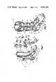
- FIG. 1is an exploded isometric view of one embodiment of a splint made in accordance with the principles of the present invention ready to be applied to the left lower extremity;
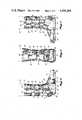
- FIG. 2is an isometric view of the splint of FIG. 1 secured in place on the left lower extremity;
- FIG. 3is a side elevational view of the splint of FIG. 1 in place on the left lower extremity from the medial aspect;
- FIG. 4is a front elevational view of the splint of FIG. 1 in place on the left lower extremity;
- FIG. 5is a side elevational view of the splint of FIG. 1 in place on the left lower extremity from the lateral aspect;
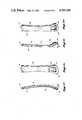
- FIG. 6Ais a front elevational view of the medial member of the splint of FIG. 1 for the left lower extremity;
- FIG. 6Bis a side elevational view of the medial member of the splint of FIG. 1;
- FIG. 7Ais a front elevational view of the lateral member of the splint of FIG. 1 for the left lower extremity;
- FIG. 7Bis a side elevational view of the lateral member of the splint of FIG. 1;
- FIG. 8is a plan view of the splint of FIG. 1 for the left lower extremity in the assembled condition.
- FIG. 9is a detailed view in expanded scale of a portion of the posterior member of the splint of FIG. 1 for the left lower extremity.
- FIG. 1illustrates a preferred embodiment of an ankle splint made in accordance with the principles of the present invention.
- the splintcomprises a posterior member 10, an anterior member 12, a medial member 14, and a lateral member 16.
- the membersare formed so that they encompass and hold firm the lower leg and foot of the patient to substantially immobilize the ankle joint during healing of an ankle sprain.
- the splint, in its assembled state, positioned on a lower leg 13 and foot 15 of a personis shown in FIGS. 2, 3, 4 and 5.
- the posterior member 10is the largest component of the splint.
- the posterior memberis generally L-shaped and includes a vertical portion 18 that supports the posterior aspect of the leg from approximately the midcalf of the leg downwardly to the heel.
- the posterior memberwraps around the heel to provide an underlying platform portion 20 upon which the foot of the patient rests.
- the vertical portion 18is typically comprised of an outer plastic shell that is approximately 0.3 centimeters thick at the proximal (upper) end and gradually becomes thicker (approximately 1.0 centimeters) over the Achilles tendon aspect where more support is needed.
- the vertical portion 18 and the platform portion 20 of the posterior member 10form substantially a right angle.
- the posterior memberhas a heel recess formed therein to accommodate the heel of the wearer.
- the heel recessis typically approximately 7.5 centimeters at its widest diameter for an adult splint. (Unless specified all further dimensions will be given for a size of splint that will fit an average adult male.)
- the plastic foot platform portion 20is approximately 2.5 centimeters thick except for the medial aspect in which it becomes gradually thicker under the arch of the foot to create an arch support portion 22.
- the maximum thickness of the arch support portion 22is approximately 5.0 centimeters.
- the undersurface 23 of the foot platform portion 20 of the posterior member 10preferably has a plurality of spaced grooves formed therein to increase the traction of the surface and minimize the possibility of slipping while walking.
- the groovesare best seen in FIGS. 3 and 5.
- a separate walking surface of rubber or some other antiskid materialcan be affixed to the underside of the posterior member.
- the posterior memberhas integrally formed in it four slots 24, 26, 28 and 30 for the purpose of retaining four straps 32 that encircle the members to hold them in their correct positions about the lower extremity.
- the slots 24 and 26are formed in the vertical portion 18 of the posterior member while the slot 30 is formed in the foot platform portion 20 approximately under the center of the foot.
- the fourth slot 28is formed in a portion of the posterior member behind the heel of the wearer at approximately the place where the vertical portion 18 and foot platform portion 20 meet.
- the slotshave inside dimensions of approximately 5.0 centimeters by 0.5 centimeters to snugly contain a portion of the fastener straps 32 which pass through the slots.
- the entire inner surface of the posterior member 10is lined with a layer 11 of compressible foam. The foam conforms more comfortably to the immobilized lower extremity than the hard plastic shell of the posterior member.
- the compressed foam in the preferred embodiment described hereinis approximately 1.0 centimeters thick.
- the medial member 14consists of an outer shell 34 of semi-rigid plastic material and an inner layer 36 of compressible foam material. As viewed from the medial aspect as shown in FIG. 6B, the medial member 14 has a substantially rectangular, elongated shape with a rounded distal portion 38 adapted to overlie the malleolus. The distal portion 38 has a slight anterior projection to conform to the adjacent posterior and anterior members when the splint is in place on the lower extremity and foot of the patient. In FIG. 6A, it can be seen that the medial member has an outward flare of the distal portion 38 with respect to the remaining elongate portion of the medial member of approximately 20 degrees to anatomically conform to the shape of the lower extremity.
- a recessed area 40formed in the distal portion 30 of the medial member to correspond and conform to the anatomic configuration of the medial malleolus thereby decreasing pressure over the bony prominence of the medial malleolus and concurrently allowing greater pressure to be applied over the edematous peri-malleolar tissues.
- the recessed area 40is approximately 4.0 centimeters at the widest anteroposterior diameter on the compressed foam material aspect.
- FIGS. 7A and 7Billustrate a preferred embodiment of the lateral member 16 that comprises an outer shell 42 of semi-rigid plastic material and an inner layer 44 of compressible foam material.
- the outer shellis approximately 0.3 centimeters thick while the compressible foam layer is approximately 1.0 centimeters thick.
- the lateral member 16has a generally rectangular shape with a rounded distal portion 46 that overlies the lateral malleolus when the splint is in place on the lower extremity of the patient.
- the lateral member 16is typically approximately 30 centimeters long and 4.5 centimeters wide in the central portion.
- the distal portion 46is flared outwardly approximately 20 degrees with respect to the elongate portion of the lateral member to conform to the anatomical configuration of the lateral aspect of the lower extremity.
- the recessed area 48is approximately 3.0 centimeter at the widest anteroposterior diameter on the compressed foam material aspect. Note that the recessed portion 48 of the lateral member 16 is slightly smaller than the recessed portion 40 of the medial member 14. This again takes into consideration the anatomical makeup of the typical lower extremity.
- the anterior member 12covers the anterior portion of the lower leg and a portion of the dorsum of the foot. It is positioned between the medial and lateral members 14 and 16.
- the anterior memberconsists of a plastic outer shell 50 and an inner compressible foam layer 52.
- the anterior member 12is formed in such a fashion as to conform to the anatomical configuration of the lower extremity.
- the proximal (upper) portion 54is of a height equal to the lateral, medial and posterior members, and for a typical adult male it is approximately 7.5 centimeters at its widest point. As the anterior member descends toward the ankle, it narrows to accommodate the typical narrowing of the leg and, again, for a typical adult male narrows to approximately 4.5 centimeters.
- the anterior memberthen flares out again over the dorsum of the foot where it is formed in a convex manner with the apex of the convexity overlying the first metatarsal bone.
- the flared portion of the anterior member 12overlies the proximal portion of the metatarsal bones and the general anatomical conformity allows a snug fit to be obtained between the anterior member 12 and the foot 15.
- the flared portion of the anterior memberstops short of covering the metatarsophalangeal joint because wide individual anatomical disparities caused by bunions, callouses, etc., preclude a uniformly comfortable fit.
- the anterior member 12comprises an outer shell 51 of semi-rigid plastic material and is lined with a layer 53 of compressible foam material.
- the fastener straps 32are used to hold the lateral, medial, anterior and posterior members in place, securely positioned about the lower extremity.
- the straps 32are secured by passing through the previously described retainer slots 24, 26, 28 and 30 formed in the posterior member 10.
- the strapsare approximately 5.0 centimeters wide and are made of a durable fabric material.
- FIGS. 3, 4 and 5show, from various views, the use of the straps 32 in holding the members securely to the lower extremity of the patient as the splint is used to immobilize the ankle joint.
- Each of the fastener straps, as viewed in FIG. 8,wraps completely around the four members and passes through a rectangular ring 61 affixed to a first end of the strap.
- FIG. 9illustrates in greater detail how the strap 32 passes through one of the retainer slots 24 and loops through the rectangular ring 61.
- the straps 32are made of a loop fastener component material such as used in combination with a hook fastener component material to form the hook and loop fastening system such as that sold under the trade name VELCRO.
- a second end of the straphas a piece of the hook fastener component affixed to it and the second end can therefore be attached to the body of the strap when the strap is pulled tight.
- hook and loop fastening meansas opposed to a simple buckle, provides for continuous adjustability range for the strap to conform to the wide range of sizes of patients. Therefore, patients within a range of sizes can use the same splint and a separate customized splint does not have to be made for each individual patient. This lowers substantially the cost involved in the use of the ankle splint of the present invention.
- the lateral, medial and anterior memberseach have a respective strip 60, 62 and 64, respectively, of the hook component of the fastening material affixed to approximately the midline of the longitudinal axis of each of the respective plastic outer shells. Since the strap itself is comprised of the loop component material of the hook and loop fastener system, the strips 60, 62, and 64 attached to the lateral, medial and anterior members will adhere to the strips of material to provide multidirectional position adjustment and to assist in holding the lateral and medial members in place vertically on the lower extremity and, also holding the anterior member in place firmly against the dorsum of the foot of the patient.
- the rectangular rings 61are of a size large enough to prevent their passing through the slots in the posterior member.
- the end of the fastener strapsloop through the rectangular rings and then double back and secure upon themselves by means of the hook and loop fastening characteristics. If one considers the rings in the sense of pulleys, in accordance with physical principles, the mechanical advantage obtained by pulling the strap against the ring to apply more tension in tightening the straps provides a more firm fit of the splint to the leg.
- the make-up of the various straps 32 and strips 60, 62 and 64can either be hook or loop components of the fastening system as long as the two comprise a cooperative pair to enable the strap to adhere to the respective strips.
- a multimembered splint for placement upon the lower extremity and foot of a patient to immobilize the ankle joint of the patient in the process of treatment of an ankle sprainincludes four members that surround the lower extremity and foot and are held in place by adjustable straps.
- the membersconform anatomically to the characteristics of the lower extremity including a flare in the lateral and medial members to accommodate the natural flare of the leg and recesses in the lateral and medial members where they fit over the lateral and medial malleoli so as to reduce pressure upon the bony prominence of the malleoli but apply greater pressure to the peri-malleolar tissues to reduce edema and prevent pressure sores.
Landscapes
- Health & Medical Sciences (AREA)
- Nursing (AREA)
- Orthopedic Medicine & Surgery (AREA)
- Engineering & Computer Science (AREA)
- Biomedical Technology (AREA)
- Heart & Thoracic Surgery (AREA)
- Vascular Medicine (AREA)
- Life Sciences & Earth Sciences (AREA)
- Animal Behavior & Ethology (AREA)
- General Health & Medical Sciences (AREA)
- Public Health (AREA)
- Veterinary Medicine (AREA)
- Orthopedics, Nursing, And Contraception (AREA)
Abstract
Description
Claims (13)
Priority Applications (1)
| Application Number | Priority Date | Filing Date | Title |
|---|---|---|---|
| US06/515,771US4505269A (en) | 1983-07-21 | 1983-07-21 | Ankle splint |
Applications Claiming Priority (1)
| Application Number | Priority Date | Filing Date | Title |
|---|---|---|---|
| US06/515,771US4505269A (en) | 1983-07-21 | 1983-07-21 | Ankle splint |
Publications (1)
| Publication Number | Publication Date |
|---|---|
| US4505269Atrue US4505269A (en) | 1985-03-19 |
Family
ID=24052671
Family Applications (1)
| Application Number | Title | Priority Date | Filing Date |
|---|---|---|---|
| US06/515,771Expired - LifetimeUS4505269A (en) | 1983-07-21 | 1983-07-21 | Ankle splint |
Country Status (1)
| Country | Link |
|---|---|
| US (1) | US4505269A (en) |
Cited By (48)
| Publication number | Priority date | Publication date | Assignee | Title |
|---|---|---|---|---|
| US4628945A (en)* | 1985-01-25 | 1986-12-16 | Johnson Jr Glenn W | Inflatable ankle brace with porous compressible filler |
| US4693239A (en)* | 1986-01-21 | 1987-09-15 | Orthomedics, Inc. | Orthosis |
| FR2605515A1 (en)* | 1986-10-27 | 1988-04-29 | Tasserit Ets | Immobilisation splint |
| US4774936A (en)* | 1985-01-23 | 1988-10-04 | Meola Antonietta M | Stabilizing prosthesis device particularly for use by paraplegic patients |
| EP0332960A1 (en)* | 1988-03-12 | 1989-09-20 | Roman Maier | Splints for members, especially for lower leg fractures |
| US4922895A (en)* | 1984-12-03 | 1990-05-08 | Andrew Chong | Orthosis for metatarsus adductus |
| US4966134A (en)* | 1987-02-24 | 1990-10-30 | Brewer Jeffrey L | Ankle protector |
| US4977891A (en)* | 1989-11-08 | 1990-12-18 | Royce Medical Company | Variable support ankle brace |
| US5020523A (en)* | 1990-10-09 | 1991-06-04 | Capra Resources, Inc. | Foot and leg splint device |
| US5399152A (en)* | 1990-09-13 | 1995-03-21 | Habermeyer; Peter | Apparatus for treating fractures in extremities |
| US5425701A (en)* | 1994-01-21 | 1995-06-20 | Minnesota Mining And Manufacturing Company | Orthopedic brace having width adjusting vamp |
| EP0674889A1 (en)* | 1994-04-01 | 1995-10-04 | Beiersdorf Aktiengesellschaft | Knee-brace |
| US5735805A (en)* | 1997-02-26 | 1998-04-07 | Restorative Care Of America Incorporated | Foot orthosis with detachable sole plate |
| US6361514B1 (en) | 2001-02-23 | 2002-03-26 | Brown Medical Industries | Universal ankle splint |
| US6361516B1 (en) | 2000-11-09 | 2002-03-26 | Christopher Ronald Hamel | Posterior ankle splint shaper |
| US20030125653A1 (en)* | 2001-12-28 | 2003-07-03 | Meyer Grant C. | D-DAFO (DeRoss-dynamic ankle foot orthosis) |
| US6595937B1 (en)* | 2000-12-21 | 2003-07-22 | Byong-Soon Moon | Bent splint and method of manufacturing the same |
| US6684096B2 (en)* | 2000-12-15 | 2004-01-27 | Berndt P. Schmit | Restraining apparatus and method for use in imaging procedures |
| US20060173390A1 (en)* | 2005-01-31 | 2006-08-03 | Robert Van Wyk | Immobilizing assembly and methods for use in diagnostic and therapeutic procedures |
| US7384584B2 (en) | 2004-12-21 | 2008-06-10 | Orthomerica Products, Inc. | Diabetic walker |
| US20080294083A1 (en)* | 2007-05-21 | 2008-11-27 | Julia Chang | Orthopedic device |
| US20090042462A1 (en)* | 2007-08-06 | 2009-02-12 | Deka Products Limited Partnership | Swimming Propulsion Device |
| US20090287127A1 (en)* | 2008-05-15 | 2009-11-19 | Irving Hu | Circumferential walker |
| USD616556S1 (en) | 2009-09-22 | 2010-05-25 | Ossur Hf | Orthopedic device |
| US20100217168A1 (en)* | 2005-06-23 | 2010-08-26 | Marcus James King | Orthosis |
| USD634852S1 (en) | 2009-09-22 | 2011-03-22 | Ossur Hf | Sole for orthopedic device |
| USD643537S1 (en) | 2009-09-22 | 2011-08-16 | Ossur Hf | Pump for an orthopedic device |
| US20130274641A1 (en)* | 2012-04-16 | 2013-10-17 | Glenn Douglas Dolfi, JR. | Achilles tendon protector |
| USD729393S1 (en) | 2014-03-27 | 2015-05-12 | Ossur Hf | Outsole for an orthopedic device |
| USD742017S1 (en) | 2014-03-27 | 2015-10-27 | Ossur Hf | Shell for an orthopedic device |
| USD744111S1 (en) | 2014-03-27 | 2015-11-24 | Ossur Hf | Orthopedic device |
| US9248042B2 (en) | 2012-09-12 | 2016-02-02 | Yessenia Lopez | Dorsal foot splint |
| US9492305B2 (en) | 2013-03-15 | 2016-11-15 | Ortho Systems | Orthopedic walking boot with heel cushion |
| US9510965B2 (en) | 2014-07-01 | 2016-12-06 | Ortho Systems | Adjustable walking apparatus |
| US9668907B2 (en) | 2013-09-25 | 2017-06-06 | Ossur Iceland Ehf | Orthopedic device |
| US9744065B2 (en) | 2013-09-25 | 2017-08-29 | Ossur Hf | Orthopedic device |
| KR101781630B1 (en) | 2017-02-20 | 2017-09-25 | 언 이 | One body type splint |
| US9839549B2 (en) | 2013-09-25 | 2017-12-12 | Ossur Iceland Ehf | Orthopedic device |
| US9839548B2 (en) | 2013-09-25 | 2017-12-12 | Ossur Iceland Ehf | Orthopedic device |
| US10039664B2 (en) | 2013-03-15 | 2018-08-07 | Ortho Systems | Overmolding for an orthopedic walking boot |
| US10058143B2 (en) | 2013-12-12 | 2018-08-28 | Ossur Hf | Outsole for orthopedic device |
| CN108992228A (en)* | 2018-07-19 | 2018-12-14 | 厦门杰斯医疗器械有限公司 | Foot joint rehabilitation bracket |
| USD846130S1 (en) | 2018-01-31 | 2019-04-16 | Ortho Systems | Knee brace |
| US10391211B2 (en) | 2015-01-26 | 2019-08-27 | Ossur Iceland Ehf | Negative pressure wound therapy orthopedic device |
| US10449078B2 (en) | 2013-03-15 | 2019-10-22 | Ovation Medical | Modular system for an orthopedic walking boot |
| US10863791B2 (en) | 2011-04-07 | 2020-12-15 | Ovation Medical | Removable leg walker |
| US10939723B2 (en) | 2013-09-18 | 2021-03-09 | Ossur Hf | Insole for an orthopedic device |
| US12156825B2 (en) | 2018-02-02 | 2024-12-03 | Ossur Iceland Ehf | Orthopedic walker |
Citations (8)
| Publication number | Priority date | Publication date | Assignee | Title |
|---|---|---|---|---|
| US3584402A (en)* | 1970-04-08 | 1971-06-15 | Jack J Silverman | Sandal for foot cast |
| US3800789A (en)* | 1972-10-13 | 1974-04-02 | R Schloss | Joint-immobilizing temporary splint |
| US4177583A (en)* | 1978-04-13 | 1979-12-11 | Chapman Andrew W | Orthopedic shoe with forefoot protective guard |
| US4217893A (en)* | 1977-08-01 | 1980-08-19 | Payton Hugh W | Above-the-knee cast |
| US4289122A (en)* | 1979-04-23 | 1981-09-15 | Mason Randy D F | Ankle-foot orthosis |
| US4414965A (en)* | 1981-05-26 | 1983-11-15 | Mauldin Donald M | Brace for tibial fractures |
| USD272281S (en) | 1981-09-28 | 1984-01-17 | Ballert Orthopedic Corp. | Contracture control orthosis |
| US4454871A (en)* | 1980-09-29 | 1984-06-19 | Med-Con, Inc. | Ankle-foot orthosis |
- 1983
- 1983-07-21USUS06/515,771patent/US4505269A/ennot_activeExpired - Lifetime
Patent Citations (8)
| Publication number | Priority date | Publication date | Assignee | Title |
|---|---|---|---|---|
| US3584402A (en)* | 1970-04-08 | 1971-06-15 | Jack J Silverman | Sandal for foot cast |
| US3800789A (en)* | 1972-10-13 | 1974-04-02 | R Schloss | Joint-immobilizing temporary splint |
| US4217893A (en)* | 1977-08-01 | 1980-08-19 | Payton Hugh W | Above-the-knee cast |
| US4177583A (en)* | 1978-04-13 | 1979-12-11 | Chapman Andrew W | Orthopedic shoe with forefoot protective guard |
| US4289122A (en)* | 1979-04-23 | 1981-09-15 | Mason Randy D F | Ankle-foot orthosis |
| US4454871A (en)* | 1980-09-29 | 1984-06-19 | Med-Con, Inc. | Ankle-foot orthosis |
| US4414965A (en)* | 1981-05-26 | 1983-11-15 | Mauldin Donald M | Brace for tibial fractures |
| USD272281S (en) | 1981-09-28 | 1984-01-17 | Ballert Orthopedic Corp. | Contracture control orthosis |
Cited By (73)
| Publication number | Priority date | Publication date | Assignee | Title |
|---|---|---|---|---|
| US4922895A (en)* | 1984-12-03 | 1990-05-08 | Andrew Chong | Orthosis for metatarsus adductus |
| US4774936A (en)* | 1985-01-23 | 1988-10-04 | Meola Antonietta M | Stabilizing prosthesis device particularly for use by paraplegic patients |
| US4628945A (en)* | 1985-01-25 | 1986-12-16 | Johnson Jr Glenn W | Inflatable ankle brace with porous compressible filler |
| US4693239A (en)* | 1986-01-21 | 1987-09-15 | Orthomedics, Inc. | Orthosis |
| FR2605515A1 (en)* | 1986-10-27 | 1988-04-29 | Tasserit Ets | Immobilisation splint |
| US4966134A (en)* | 1987-02-24 | 1990-10-30 | Brewer Jeffrey L | Ankle protector |
| EP0332960A1 (en)* | 1988-03-12 | 1989-09-20 | Roman Maier | Splints for members, especially for lower leg fractures |
| US4977891A (en)* | 1989-11-08 | 1990-12-18 | Royce Medical Company | Variable support ankle brace |
| US5399152A (en)* | 1990-09-13 | 1995-03-21 | Habermeyer; Peter | Apparatus for treating fractures in extremities |
| US5020523A (en)* | 1990-10-09 | 1991-06-04 | Capra Resources, Inc. | Foot and leg splint device |
| WO1992005751A1 (en)* | 1990-10-09 | 1992-04-16 | Capra Resources, Inc. | Foot and leg splint device |
| US5425701A (en)* | 1994-01-21 | 1995-06-20 | Minnesota Mining And Manufacturing Company | Orthopedic brace having width adjusting vamp |
| EP0674889A1 (en)* | 1994-04-01 | 1995-10-04 | Beiersdorf Aktiengesellschaft | Knee-brace |
| US5735805A (en)* | 1997-02-26 | 1998-04-07 | Restorative Care Of America Incorporated | Foot orthosis with detachable sole plate |
| US6361516B1 (en) | 2000-11-09 | 2002-03-26 | Christopher Ronald Hamel | Posterior ankle splint shaper |
| US6684096B2 (en)* | 2000-12-15 | 2004-01-27 | Berndt P. Schmit | Restraining apparatus and method for use in imaging procedures |
| US6595937B1 (en)* | 2000-12-21 | 2003-07-22 | Byong-Soon Moon | Bent splint and method of manufacturing the same |
| US6361514B1 (en) | 2001-02-23 | 2002-03-26 | Brown Medical Industries | Universal ankle splint |
| US20030125653A1 (en)* | 2001-12-28 | 2003-07-03 | Meyer Grant C. | D-DAFO (DeRoss-dynamic ankle foot orthosis) |
| US6860864B2 (en)* | 2001-12-28 | 2005-03-01 | Grant C. Meyer | D-DAFO (DeRoss-dynamic ankle foot orthosis) |
| US7384584B2 (en) | 2004-12-21 | 2008-06-10 | Orthomerica Products, Inc. | Diabetic walker |
| US20060173390A1 (en)* | 2005-01-31 | 2006-08-03 | Robert Van Wyk | Immobilizing assembly and methods for use in diagnostic and therapeutic procedures |
| US20100217168A1 (en)* | 2005-06-23 | 2010-08-26 | Marcus James King | Orthosis |
| US20080294083A1 (en)* | 2007-05-21 | 2008-11-27 | Julia Chang | Orthopedic device |
| US9943431B2 (en) | 2007-05-21 | 2018-04-17 | Ossur Hf | Orthopedic device |
| US7727174B2 (en) | 2007-05-21 | 2010-06-01 | Ossur Hf | Orthopedic device |
| US20110196275A1 (en)* | 2007-05-21 | 2011-08-11 | Julia Chang | Orthopedic device |
| US20090042462A1 (en)* | 2007-08-06 | 2009-02-12 | Deka Products Limited Partnership | Swimming Propulsion Device |
| WO2009021013A3 (en)* | 2007-08-06 | 2009-09-11 | Deka Products Limited Partnership | Swimming propulsion device |
| US7988508B2 (en)* | 2007-08-06 | 2011-08-02 | Deka Products Limited Partnership | Swimming propulsion device |
| US8506510B2 (en) | 2008-05-15 | 2013-08-13 | Ossur Hf | Circumferential walker |
| US10064749B2 (en) | 2008-05-15 | 2018-09-04 | Ossur Hf | Circumferential walker |
| US20100234782A1 (en)* | 2008-05-15 | 2010-09-16 | Irving Hu | Circumferential walker |
| US20090287127A1 (en)* | 2008-05-15 | 2009-11-19 | Irving Hu | Circumferential walker |
| US8002724B2 (en) | 2008-05-15 | 2011-08-23 | Ossur Hf | Circumferential walker |
| US20120078148A1 (en)* | 2008-05-15 | 2012-03-29 | Irving Hu | Circumferential walker |
| US9468553B2 (en) | 2008-05-15 | 2016-10-18 | Ossur Hf | Circumferential walker |
| US9333106B2 (en)* | 2008-05-15 | 2016-05-10 | Ossur Hf | Circumferential walker |
| US9220621B2 (en) | 2008-05-15 | 2015-12-29 | Ossur Hf | Circumferential walker |
| US9492301B2 (en) | 2008-05-15 | 2016-11-15 | Ossur Hf | Circumferential walker |
| USD634852S1 (en) | 2009-09-22 | 2011-03-22 | Ossur Hf | Sole for orthopedic device |
| USD616556S1 (en) | 2009-09-22 | 2010-05-25 | Ossur Hf | Orthopedic device |
| USD643537S1 (en) | 2009-09-22 | 2011-08-16 | Ossur Hf | Pump for an orthopedic device |
| US10863791B2 (en) | 2011-04-07 | 2020-12-15 | Ovation Medical | Removable leg walker |
| US20130274641A1 (en)* | 2012-04-16 | 2013-10-17 | Glenn Douglas Dolfi, JR. | Achilles tendon protector |
| US9248042B2 (en) | 2012-09-12 | 2016-02-02 | Yessenia Lopez | Dorsal foot splint |
| US10085871B2 (en) | 2013-03-15 | 2018-10-02 | Ovation Systems | Overmolding for an orthopedic walking boot |
| US10449078B2 (en) | 2013-03-15 | 2019-10-22 | Ovation Medical | Modular system for an orthopedic walking boot |
| US9492305B2 (en) | 2013-03-15 | 2016-11-15 | Ortho Systems | Orthopedic walking boot with heel cushion |
| US10039664B2 (en) | 2013-03-15 | 2018-08-07 | Ortho Systems | Overmolding for an orthopedic walking boot |
| US10939723B2 (en) | 2013-09-18 | 2021-03-09 | Ossur Hf | Insole for an orthopedic device |
| US11969373B2 (en) | 2013-09-25 | 2024-04-30 | Ossur Iceland Ehf | Orthopedic device |
| US10993826B2 (en) | 2013-09-25 | 2021-05-04 | Ossur Iceland Ehf | Orthopedic device |
| US9668907B2 (en) | 2013-09-25 | 2017-06-06 | Ossur Iceland Ehf | Orthopedic device |
| US9744065B2 (en) | 2013-09-25 | 2017-08-29 | Ossur Hf | Orthopedic device |
| US10646368B2 (en) | 2013-09-25 | 2020-05-12 | Ossur Hf | Orthopedic device |
| US9839550B2 (en) | 2013-09-25 | 2017-12-12 | Ossur Hf | Orthopedic device |
| US9839549B2 (en) | 2013-09-25 | 2017-12-12 | Ossur Iceland Ehf | Orthopedic device |
| US9839548B2 (en) | 2013-09-25 | 2017-12-12 | Ossur Iceland Ehf | Orthopedic device |
| US10058143B2 (en) | 2013-12-12 | 2018-08-28 | Ossur Hf | Outsole for orthopedic device |
| USD744111S1 (en) | 2014-03-27 | 2015-11-24 | Ossur Hf | Orthopedic device |
| USD742017S1 (en) | 2014-03-27 | 2015-10-27 | Ossur Hf | Shell for an orthopedic device |
| USD776288S1 (en) | 2014-03-27 | 2017-01-10 | Ossur Hf | Shell for an orthopedic device |
| USD776289S1 (en) | 2014-03-27 | 2017-01-10 | Ossur Hf | Shell for an orthopedic device |
| USD729393S1 (en) | 2014-03-27 | 2015-05-12 | Ossur Hf | Outsole for an orthopedic device |
| USD772418S1 (en) | 2014-03-27 | 2016-11-22 | Ossur Hf | Shell for an orthopedic device |
| US10449077B2 (en) | 2014-07-01 | 2019-10-22 | Ovation Medical | Adjustable walking apparatus |
| US9510965B2 (en) | 2014-07-01 | 2016-12-06 | Ortho Systems | Adjustable walking apparatus |
| US10391211B2 (en) | 2015-01-26 | 2019-08-27 | Ossur Iceland Ehf | Negative pressure wound therapy orthopedic device |
| KR101781630B1 (en) | 2017-02-20 | 2017-09-25 | 언 이 | One body type splint |
| USD846130S1 (en) | 2018-01-31 | 2019-04-16 | Ortho Systems | Knee brace |
| US12156825B2 (en) | 2018-02-02 | 2024-12-03 | Ossur Iceland Ehf | Orthopedic walker |
| CN108992228A (en)* | 2018-07-19 | 2018-12-14 | 厦门杰斯医疗器械有限公司 | Foot joint rehabilitation bracket |
Similar Documents
| Publication | Publication Date | Title |
|---|---|---|
| US4505269A (en) | Ankle splint | |
| US6361514B1 (en) | Universal ankle splint | |
| EP0955818B1 (en) | Orthopedic cast walker boot | |
| US5799659A (en) | Ankle foot orthosis night splint with orthowedge | |
| US4217893A (en) | Above-the-knee cast | |
| US4057056A (en) | Walking cast | |
| US5776090A (en) | Means and method for treating Plantar Fasciitis | |
| US5843010A (en) | Heel and ankle appliance | |
| US7727173B2 (en) | Method and apparatus for the treatment of plantar ulcers and foot deformities | |
| US4693239A (en) | Orthosis | |
| US6056713A (en) | Moldable custom-fitted ankle brace | |
| US5897520A (en) | Unitary dorsal night splint | |
| US4554912A (en) | Plastic orthotic therapeutic device | |
| US5306230A (en) | Knee extending orthotic appliance | |
| US6485447B1 (en) | Foot support device with adjustable forefoot rocker angle | |
| US8226589B2 (en) | Night splint with digital dorsiflexion | |
| US7572241B2 (en) | Orthopedic night foot splint | |
| US6945946B2 (en) | Method and apparatus for the treatment of plantar ulcers and foot deformities | |
| US9320637B2 (en) | Dynamic hallux tension device for treatment of plantar faciitis | |
| US5199941A (en) | Contoured ankle brace and stabilizer | |
| US6793640B1 (en) | Ankle support | |
| US4370976A (en) | Dynamic foam orthosis | |
| US20050222531A1 (en) | Ankle braces | |
| Cusick et al. | Short leg casts: Their role in the management of cerebral palsy | |
| US9351865B2 (en) | Apparatus for plantar fasciitis treatment and method for making same |
Legal Events
| Date | Code | Title | Description |
|---|---|---|---|
| STCF | Information on status: patent grant | Free format text:PATENTED CASE | |
| FEPP | Fee payment procedure | Free format text:PAYOR NUMBER ASSIGNED (ORIGINAL EVENT CODE: ASPN); ENTITY STATUS OF PATENT OWNER: SMALL ENTITY | |
| AS | Assignment | Owner name:D-R SPLINT CORPORATION, 145 THIRD SOUTH, EDMONDS, Free format text:ASSIGNMENT OF ASSIGNORS INTEREST.;ASSIGNORS:DAVIES, JOHN, R.,;RICE, GLEN V.;REEL/FRAME:004869/0699 Effective date:19880427 Owner name:D-R SPLINT CORPORATION,WASHINGTON Free format text:ASSIGNMENT OF ASSIGNORS INTEREST;ASSIGNORS:DAVIES, JOHN, R.,;RICE, GLEN V.;REEL/FRAME:004869/0699 Effective date:19880427 | |
| FPAY | Fee payment | Year of fee payment:4 | |
| FPAY | Fee payment | Year of fee payment:8 | |
| AS | Assignment | Owner name:APPLE MEDICAL, INC., COLORADO Free format text:ASSIGNMENT OF ASSIGNORS INTEREST;ASSIGNOR:D-R SPLINT CORPORATION;REEL/FRAME:008006/0291 Effective date:19941215 | |
| AS | Assignment | Owner name:APPLE MEDICAL MANUFACTURING COMPANY, INC., COLORAD Free format text:ASSIGNMENT OF ASSIGNORS INTEREST;ASSIGNOR:APPLE MEDICAL, INC.;REEL/FRAME:008006/0932 Effective date:19960621 | |
| FPAY | Fee payment | Year of fee payment:12 | |
| FEPP | Fee payment procedure | Free format text:PAYOR NUMBER ASSIGNED (ORIGINAL EVENT CODE: ASPN); ENTITY STATUS OF PATENT OWNER: SMALL ENTITY Free format text:PAYER NUMBER DE-ASSIGNED (ORIGINAL EVENT CODE: RMPN); ENTITY STATUS OF PATENT OWNER: SMALL ENTITY | |
| AS | Assignment | Owner name:WILLIAM M. HODGES, JR., FLORIDA Free format text:ASSIGNMENT OF ASSIGNORS INTEREST;ASSIGNOR:APPLE MEDICAL MANUFACTURING COMPANY;REEL/FRAME:009748/0471 Effective date:19981013 Owner name:ANNE M. HODGES, FLORIDA Free format text:ASSIGNMENT OF ASSIGNORS INTEREST;ASSIGNOR:APPLE MEDICAL MANUFACTURING COMPANY;REEL/FRAME:009748/0471 Effective date:19981013 Owner name:TYCOR MEDICAL, INC., FLORIDA Free format text:ASSIGNMENT OF ASSIGNORS INTEREST;ASSIGNORS:HODGES, WILLIAM M., JR.;HODGES, ANNE M.;REEL/FRAME:009748/0465 Effective date:19990119 | |
| AS | Assignment | Owner name:BROWN MEDICAL INDUSTRIES, IOWA Free format text:ASSIGNMENT OF ASSIGNORS INTEREST;ASSIGNOR:TYCOR MEDICAL, INC.;REEL/FRAME:010288/0130 Effective date:19990930 |