US4502937A - Optical fiber joint type ion-concentration measurement apparatus - Google Patents
Optical fiber joint type ion-concentration measurement apparatusDownload PDFInfo
- Publication number
- US4502937A US4502937AUS06/528,985US52898583AUS4502937AUS 4502937 AUS4502937 AUS 4502937AUS 52898583 AUS52898583 AUS 52898583AUS 4502937 AUS4502937 AUS 4502937A
- Authority
- US
- United States
- Prior art keywords
- signals
- optical fiber
- voltage
- frequency
- measurement apparatus
- Prior art date
- Legal status (The legal status is an assumption and is not a legal conclusion. Google has not performed a legal analysis and makes no representation as to the accuracy of the status listed.)
- Expired - Fee Related
Links
- 239000013307optical fiberSubstances0.000titleclaimsabstractdescription23
- 238000005259measurementMethods0.000titleclaimsabstractdescription16
- 239000003990capacitorSubstances0.000claimsabstractdescription17
- 238000007599dischargingMethods0.000claimsabstractdescription12
- 230000003287optical effectEffects0.000claimsabstractdescription7
- 150000002500ionsChemical class0.000description14
- 238000010276constructionMethods0.000description6
- 238000010586diagramMethods0.000description5
- 239000004973liquid crystal related substanceSubstances0.000description4
- 230000005540biological transmissionEffects0.000description2
- 238000000034methodMethods0.000description2
- 150000001450anionsChemical class0.000description1
- 230000000694effectsEffects0.000description1
- 239000011521glassSubstances0.000description1
Images


Classifications
- G—PHYSICS
- G01—MEASURING; TESTING
- G01N—INVESTIGATING OR ANALYSING MATERIALS BY DETERMINING THEIR CHEMICAL OR PHYSICAL PROPERTIES
- G01N27/00—Investigating or analysing materials by the use of electric, electrochemical, or magnetic means
- G01N27/26—Investigating or analysing materials by the use of electric, electrochemical, or magnetic means by investigating electrochemical variables; by using electrolysis or electrophoresis
- G01N27/28—Electrolytic cell components
Definitions
- the present inventionrelates to an optical fiber joint type ion-concentration measurement apparatus in which electrical signals which are detected by an ion selective electrode are transformed into optical signals which are transmitted to a receiving side of the apparatus by means of optical fibers.
- the present inventionprovides an improved optical fiber joint type ion-concentration measurement apparatus in which LED devices, which emit light by themselves, are used, said LED devices being able to be driven by very small amounts of electrical power, and, in spite of it, the signals detected by an ion selective electrode can be transmitted to the receiving side with a high fidelity.
- FIG. 2is a schematic diagram of a preferred embodiment of the transmitting side circuit in the case of the invention being applied to a pH meter;
- FIG. 4is a schematic diagram of a preamplifier which may be applied to a ORP meter or anion meter;
- FIG. 5is a schematic diagram of a preferred embodiment of the receiving side circuit.
- FIG. 1showing the basic construction of the present invention
- numeral 1denotes the transmitting side
- numeral 2denotes the receiving side
- numeral 3denotes an optical fiber for transmitting light from the transmitting side 1 to the receiving side 2.
- the receiving side 2consists of a light receiving element 4, an amplifier 5, a frequency/voltage converter 6 and an indicating meter 7.
- the transmitting side 1consists of an ion selective electrode 8, an amplifier 9 for amplifying signals detected by the ion selective electrode 8, a voltage/frequency converter 10 for frequency modulating signals output by the amplifier 9, a switch means, e.g., a PUT, which is switched on or off by the signals output by the voltage/frequency converter 10, an LED 11 which is connected in series with the PUT, a charging circuit 12 including batteries B 1 and B 2 , and a charging-discharging capacitor 13 having a series circuit which consists of the PUT and the LED 11 and which is used as a discharging circuit.
- R 1is an electrical resistance used for adjusting the charging current
- R 2is an electrical resistance used for adjusting the discharging current.
- R 1is preferably selected so as to be as large as possible with the object of reducing the electrical power consumption and R 2 is preferably selected so as to be as small as possible with the object of increasing the illuminating power of the LED.
- the detecting signals which are generated by the ion selective electrode 8are fed to the voltage/frequency converter 10 through the amplifier 9, where they are frequency modulated.
- the PUTis switched on or off with the same frequency as the frequency modulated signals.
- the capacitor 13is charged by the charging circuit 12, and when the PUT is switched on, the charge is momentarily discharged through the PUT, the electrical resistance R 2 , and the LED 11.
- the LED 11emits light in a very short period of time.
- the LED 11emits light at the same frequency as the frequency at which the PUT is switched on, that is to say, at the frequency of the signals obtained by modulating the signals which were output by the ion selective electrode 8.
- the output signals from the converter 6correspond to the signals from said ion selective electrode 8, and thus, the indicating meter 7 can be actuated.
- the mean current i which passes through the LED 11may be expressed by the following equation:
- Cis the capacitance of the capacitor 13;
- V B1is the voltage of the battery B 1 ;
- V B2is the voltage of the battery B 2 , and
- fis the transformed frequency of the voltage/frequency converter 10. If a 0.1 ⁇ F capacitor is selected for C, and 5 Volts selected for (V B1 +V B2 ), and a range of from 10 to 100 Hz selected for f, then i can be reduced to a range of from 5 to 50 ⁇ A. Accordingly, if C, V B1 +V B2 , and f are selected as described above, the consumption of electrical power can be significantly reduced so that the transmitting side 1 can be continuously operated for about one year by four penlight batteries, IEC designation RG (size AA).
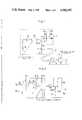
- FIG. 2showing the construction of the circuit of the transmitting side in case of the invention being applied to a pH meter used as an ion-concentration measurement apparatus
- Gdenotes a connection terminal of a glass electrode
- Rdenotes a connection terminal of a reference electrode
- IC 1 and IC 2denote integrated circuits corresponding to the amplifier 9 shown in FIG. 1
- IC 3denotes a circuit corresponding to the voltage/frequency converter 10.
- R tdenotes a heat sensitive resistor used for temperature compensation.
- resistor R t and the resistance R 3which is connected in series with the resistor R t , to reduce the consumption of electrical power in the amplifier 9 (comprising IC 1 and IC 2 ) when the resistor R t having a large resistance value is unavailable, it is only necessary to select the construction shown in FIG. 3 so as to reduce the voltage across the resistor R t . That is, amplifier IC 4 is added between amplifiers IC 1 and IC 2 so as to reduce the voltage across resistor R t .
- PDdenotes a photo detector
- IC 5 , IC 7 , and IC 8denote integrated circuits used as amplifiers
- IC 6denotes an integrated circuit used as a frequency/voltage converter
- TRdenotes a transistor.
- the signals, which were demodulated by the frequency/voltage converter IC 6are current amplified by the transistor TR, and then fed to a power supply side (not shown) through double line type transmission channels l 1 and l 2 .
- the detailed description of this output circuitis omitted since it is comparatively familiar as a circuit for use with milliampere currents.
- the signals, which are transmitted by means of an optical fiberare the signals which were frequency modulated by a voltage/frequency converter, that is to say, signals which transmit information stored in their frequency, the length of the light emitting time is immaterial. Thus, the detected signals can be faithfully transmitted.
Landscapes
- Chemical & Material Sciences (AREA)
- Life Sciences & Earth Sciences (AREA)
- Health & Medical Sciences (AREA)
- Biochemistry (AREA)
- Chemical Kinetics & Catalysis (AREA)
- Electrochemistry (AREA)
- Physics & Mathematics (AREA)
- Analytical Chemistry (AREA)
- Molecular Biology (AREA)
- General Health & Medical Sciences (AREA)
- General Physics & Mathematics (AREA)
- Immunology (AREA)
- Pathology (AREA)
- Arrangements For Transmission Of Measured Signals (AREA)
- Transmission And Conversion Of Sensor Element Output (AREA)
- Investigating Or Analysing Materials By Optical Means (AREA)
Abstract
Description
1. Field of the Invention
The present invention relates to an optical fiber joint type ion-concentration measurement apparatus in which electrical signals which are detected by an ion selective electrode are transformed into optical signals which are transmitted to a receiving side of the apparatus by means of optical fibers.
2. Description of the Prior Art
An optical fiber joint type ion-concentration measurement apparatus of this kind has an advantage in that measurement errors due to disturbances and ground loop voltages can be significantly reduced in comparison to that of apparatus in which the transmitting side is connected to the receiving side by electrical cables.
However, in the conventional optical fiber joint type ion-concentration measurement apparatus, since the signals detected by an ion electrode are either amplified and used as is or the amplified signals are modulated in frequency through a voltage/frequency converter and used to cause an LED (Light Emitting Diode) to emit light, an extremely large electrical power consumption is needed and many problems must be solved in order to use them practically. That is to say, since a large consumption of electrical power is required, it is necessary to use a large-sized battery at the transmitting side or to connect the transmitting side to the receiving side by means of a power supply cable. In the former method, since the transmitting side apparatus becomes large-sized and heavy, it is difficult to carry about. In the latter method, it is not worthwhile to use an optical fiber joint type ion-concentration measurement apparatus since the advantages thereof are lost by the use of the power supply cable. At present, the apparatus, which use liquid crystal devices having a low power consumption instead of the LED devices are being proposed. However, since liquid crystal devices do not emit light by themselves but merely change the transmission of light, it is necessary to transmit the light to be irradiated to the liquid crystal devices from the receiving side, whereby the apparatus using such liquid crystal devices have disadvantages in that one more optical fiber is required and the circuit of the transmitting side is complicated in construction.
In respect of the above described points, the present invention provides an improved optical fiber joint type ion-concentration measurement apparatus in which LED devices, which emit light by themselves, are used, said LED devices being able to be driven by very small amounts of electrical power, and, in spite of it, the signals detected by an ion selective electrode can be transmitted to the receiving side with a high fidelity. The optical fiber joint type ion-concentration measurement apparatus according to the present invention comprises a transmitting side consisting of an ion selective electrode, a voltage/frequency converter for frequency modulating the signals detected by said ion selective electrode, a switch means which is switched on or off by the signals output from said converter, an LED device which is connected in series with said switch means, a charging circuit including a battery, and a charging-discharging capacitor having a series circuit consisting of said switch means and said LED device as a discharging circuit, wherein an electric charge which is accumulated in said capacitor is discharged when said switch means is switched on so as to cause said LED device to emit light, and the emitted light is transmitted to the receiving side by means of optical fibers.
The drawings show the preferred embodiment of the present invention, in which:
FIG. 1 is a schematic diagram of a basic configuration of the present invention;
FIG. 2 is a schematic diagram of a preferred embodiment of the transmitting side circuit in the case of the invention being applied to a pH meter;
FIG. 3 is a schematic diagram of a circuit having a lower electrical power consumption than that of the circuit shown in FIG. 2;
FIG. 4 is a schematic diagram of a preamplifier which may be applied to a ORP meter or anion meter; and
FIG. 5 is a schematic diagram of a preferred embodiment of the receiving side circuit.
The preferred embodiment of the present invention will be now described with reference to the drawings. Referring now to FIG. 1 showing the basic construction of the present invention,numeral 1 denotes the transmitting side;numeral 2 denotes the receiving side, and numeral 3 denotes an optical fiber for transmitting light from the transmittingside 1 to thereceiving side 2. Thereceiving side 2 consists of alight receiving element 4, anamplifier 5, a frequency/voltage converter 6 and an indicatingmeter 7. The transmittingside 1 consists of an ion selective electrode 8, anamplifier 9 for amplifying signals detected by the ion selective electrode 8, a voltage/frequency converter 10 for frequency modulating signals output by theamplifier 9, a switch means, e.g., a PUT, which is switched on or off by the signals output by the voltage/frequency converter 10, anLED 11 which is connected in series with the PUT, acharging circuit 12 including batteries B1 and B2, and a charging-dischargingcapacitor 13 having a series circuit which consists of the PUT and theLED 11 and which is used as a discharging circuit. R1 is an electrical resistance used for adjusting the charging current, and R2 is an electrical resistance used for adjusting the discharging current. R1 is preferably selected so as to be as large as possible with the object of reducing the electrical power consumption and R2 is preferably selected so as to be as small as possible with the object of increasing the illuminating power of the LED.
According to the above described construction, the detecting signals which are generated by the ion selective electrode 8 are fed to the voltage/frequency converter 10 through theamplifier 9, where they are frequency modulated. The PUT is switched on or off with the same frequency as the frequency modulated signals. When the PUT is switched off, thecapacitor 13 is charged by thecharging circuit 12, and when the PUT is switched on, the charge is momentarily discharged through the PUT, the electrical resistance R2, and theLED 11. As a result, theLED 11 emits light in a very short period of time. TheLED 11 emits light at the same frequency as the frequency at which the PUT is switched on, that is to say, at the frequency of the signals obtained by modulating the signals which were output by the ion selective electrode 8. Accordingly, if the light emitted from theLED 11 is transmitted to the receivingside 2 by means of the optical fiber 3 and fed to the frequency/voltage converter 6, the output signals from theconverter 6 correspond to the signals from said ion selective electrode 8, and thus, the indicatingmeter 7 can be actuated.
According to the above described construction, the largest part of the electrical power consumed by the transmittingside 1 is consumed by theLED 11. Provided that when the PUT is switched off, thecapacitor 13 is completely charged, and when the PUT is switched on, the charge on thecapacitor 13 is completely discharged through theLED 11, then the mean current i which passes through theLED 11 may be expressed by the following equation:
i=C(V.sub.B1 +V.sub.B2)·f
wherein C is the capacitance of thecapacitor 13; VB1 is the voltage of the battery B1 ; VB2 is the voltage of the battery B2, and f is the transformed frequency of the voltage/frequency converter 10. If a 0.1 μF capacitor is selected for C, and 5 Volts selected for (VB1 +VB2), and a range of from 10 to 100 Hz selected for f, then i can be reduced to a range of from 5 to 50 μA. Accordingly, if C, VB1 +VB2, and f are selected as described above, the consumption of electrical power can be significantly reduced so that the transmittingside 1 can be continuously operated for about one year by four penlight batteries, IEC designation RG (size AA).
The reason why the consumption of electrical power in the transmitting side can be reduced in spite of using an LED is that the LED is not driven by the signals detected by an ion selective electrode or the output signals of a voltage/frequency converter in a different fashion from a conventional apparatus but rather is due to the fact that light is emitted from the LED by discharging current from the capacitor, the detected signals from the ion selective electrode merely serving as the trigger signal for causing the starting of the discharge of the capacitor.
The preferred embodiments of the present invention will now be described with reference to FIGS. 2 to 5. Referring now to FIG. 2 showing the construction of the circuit of the transmitting side in case of the invention being applied to a pH meter used as an ion-concentration measurement apparatus, G denotes a connection terminal of a glass electrode; R denotes a connection terminal of a reference electrode; IC1 and IC2 denote integrated circuits corresponding to theamplifier 9 shown in FIG. 1, and IC3 denotes a circuit corresponding to the voltage/frequency converter 10. Rt denotes a heat sensitive resistor used for temperature compensation. Although it is necessary to increase the value of resistor Rt and the resistance R3, which is connected in series with the resistor Rt, to reduce the consumption of electrical power in the amplifier 9 (comprising IC1 and IC2) when the resistor Rt having a large resistance value is unavailable, it is only necessary to select the construction shown in FIG. 3 so as to reduce the voltage across the resistor Rt. That is, amplifier IC4 is added between amplifiers IC1 and IC2 so as to reduce the voltage across resistor Rt.
In addition, when the present invention is applied to other apparatus, such as ORP meter and a negative ion meter, since the polarity is different from the case of a pH meter, it is only necessary to change the polarity of signals, as shown in FIG. 4. That is, the input connections of amplifier IC4 are reversed.
Referring now to FIG. 5 showing the preferred example of the circuit of the receiving side for receiving optical signals transmitted from the transmitting side, PD denotes a photo detector; IC5, IC7, and IC8 denote integrated circuits used as amplifiers; IC6 denotes an integrated circuit used as a frequency/voltage converter, and TR denotes a transistor. The signals, which were demodulated by the frequency/voltage converter IC6, are current amplified by the transistor TR, and then fed to a power supply side (not shown) through double line type transmission channels l1 and l2. The detailed description of this output circuit is omitted since it is comparatively familiar as a circuit for use with milliampere currents.
When an optical fiber joint type ion-concentration measurement apparatus of the present invention includes a transmitting side which is constructed as described above, it has the following effects:
The light is emitted from an LED by discharging the charge accumulated on a capacitor in a fashion which is different from that of a conventional apparatus, in which the light is emitted by the signals output by an ion selective electrode, whereby the consumption of electrical power can be significantly reduced. In particular, the suitable selection of the transformed frequency of a voltage/frequency converter, the charging voltage, and the capacitance of the capacitor leads to the possibility of using small penlight cells. Thus, the transmitting side can be very compact and lightweight and may be used for a long period of time, whereby the practical use of the apparatus becomes very high.
Although an LED emits light for only a very short time by discharging the charge on the capacitor, since the signals, which are transmitted by means of an optical fiber, are the signals which were frequency modulated by a voltage/frequency converter, that is to say, signals which transmit information stored in their frequency, the length of the light emitting time is immaterial. Thus, the detected signals can be faithfully transmitted.
Claims (4)
1. An optical fiber joint type ion-concentration measurement apparatus having a transmitting side in which electrical signals which are detected by an ion selective electrode are transformed into optical signals and the transformed optical signals are transmitted to a receiving side of said measurement apparatus by means of an optical fiber, wherein said transmitting side comprises:
an ion selective electrode, a voltage/frequency converter coupled to said electrode for frequency modulating signals which are detected by said ion selective electrode, a switch means coupled to said converter and switched on or off by output signals from said converter, an LED device connected in series with said switch means to form a series circuit, a charging circuit including an electrical power source and a charging-discharging capacitor having said series circuit constituting of said switch means and said LED used as a discharging circuit, wherein electrical charge which is stored in said capacitor is discharged when said switch means is switched on so as to cause said LED to emit light, and wherein the light emitted from said LED is transmitted to said receiving side by means of said optical fiber.
2. An optical fiber joint type ion-concentration measurement apparatus as set forth in claim 1, wherein said output signals from said voltage/frequency converter are fed to a control input terminal of said switch means and said charge which is discharged from said charging-discharging capacitor is fed to a controlled input terminal of said switch means.
3. An optical fiber joint type ion-concentration measurement apparatus as set forth in claim 2, wherein said switch means is switched on or off at the same frequency as that of said output signals from said voltage/frequency converter.
4. An optical fiber joint type ion-concentration measurement apparatus as set forth in claim 1, wherein said switch means is switched on or off at the same frequency as that of said output signals from said voltage/frequency converter.
Applications Claiming Priority (2)
| Application Number | Priority Date | Filing Date | Title |
|---|---|---|---|
| JP57162870AJPS5951338A (en) | 1982-09-17 | 1982-09-17 | Optical fiber connecting type ion concentration measuring apparatus |
| JP57-162870 | 1982-09-17 |
Publications (1)
| Publication Number | Publication Date |
|---|---|
| US4502937Atrue US4502937A (en) | 1985-03-05 |
Family
ID=15762825
Family Applications (1)
| Application Number | Title | Priority Date | Filing Date |
|---|---|---|---|
| US06/528,985Expired - Fee RelatedUS4502937A (en) | 1982-09-17 | 1983-09-02 | Optical fiber joint type ion-concentration measurement apparatus |
Country Status (2)
| Country | Link |
|---|---|
| US (1) | US4502937A (en) |
| JP (1) | JPS5951338A (en) |
Cited By (25)
| Publication number | Priority date | Publication date | Assignee | Title |
|---|---|---|---|---|
| US4633523A (en)* | 1984-02-01 | 1986-12-30 | The United States Of America As Represented By The United States Department Of Energy | Optical analog data link with simple self-test feature |
| US4643568A (en)* | 1984-04-05 | 1987-02-17 | Telefonaktiebolaget Lm Ericsson | Method and apparatus for measuring the illuminating power of incident light |
| US4700068A (en)* | 1986-01-31 | 1987-10-13 | Hughes Aircraft Company | Apparatus and method for spatially characterizing and controlling a particle beam |
| US4767994A (en)* | 1986-09-10 | 1988-08-30 | Phillips Petroleum Company | Multi-purpose voltametric analyzer |
| US4829253A (en)* | 1987-06-03 | 1989-05-09 | Rosemount Inc. | Three wire amplifier circuit with diagnostic capabilities |
| US4853614A (en)* | 1988-03-11 | 1989-08-01 | Carver Robert L | Method and apparatus for measuring moisture content of granular material |
| US4892640A (en)* | 1985-04-16 | 1990-01-09 | Avl Ag | Sensor for the determination of electrolyte concentrations |
| US4928067A (en)* | 1988-12-19 | 1990-05-22 | Siemens Transmission Systems, Inc. | Non-intrusive fiber optic electromagnetic field probe apparatus and associated methods |
| US4998098A (en)* | 1989-01-26 | 1991-03-05 | Schweitzer Engineering Laboratories Inc. | Overvoltage detector to indicate voltage to a remote monitor |
| US5001417A (en)* | 1987-06-01 | 1991-03-19 | Abbott Laboratories | Apparatus for measuring electrolytes utilizing optical signals related to the concentration of the electrolytes |
| US5093625A (en)* | 1990-02-09 | 1992-03-03 | Graco Inc. | Electrostatic spray gun voltage and current monitor with remote readout |
| US5134359A (en)* | 1987-06-01 | 1992-07-28 | Abbott Laboratories | Apparatus for measuring electrolytes including optical measurements |
| US6281686B1 (en)* | 1997-12-27 | 2001-08-28 | Arnold Hawkins, Sr. | Nonintrusive power and continuity testing tools |
| US6388248B1 (en)* | 2000-07-06 | 2002-05-14 | Eaton Corporation | Control voltage isolation system for electrical rotating apparatus utilizing fiber optics and associated method |
| US6501581B1 (en)* | 1998-11-06 | 2002-12-31 | Ericsson Inc. | Adaptor and method for use with a light-communication device |
| US7002131B1 (en) | 2003-01-24 | 2006-02-21 | Jds Uniphase Corporation | Methods, systems and apparatus for measuring average received optical power |
| US7215883B1 (en) | 2003-01-24 | 2007-05-08 | Jds Uniphase Corporation | Methods for determining the performance, status, and advanced failure of optical communication channels |
| US20070242862A1 (en)* | 2002-07-09 | 2007-10-18 | Kaleidescape, Inc. | Watermarking and fingerprinting digital content using alternative blocks to embed information |
| US20070261493A1 (en)* | 2003-09-22 | 2007-11-15 | Hyeung-Yun Kim | Flexible diagnostic patches for structural health monitoring |
| US20070266788A1 (en)* | 2003-09-22 | 2007-11-22 | Hyeung-Yun Kim | Diagnostic systems of optical fiber coil sensors for structural health monitoring |
| US20080148853A1 (en)* | 2003-09-22 | 2008-06-26 | Hyeung-Yun Kim | Gas tank having usage monitoring system |
| US20080225376A1 (en)* | 2003-09-22 | 2008-09-18 | Hyeung-Yun Kim | Acousto-optic modulators for modulating light signals |
| US20080232999A1 (en)* | 2005-09-07 | 2008-09-25 | Fogel Kenneth D | Platinum-palladium alloy |
| US20090114589A1 (en)* | 2006-05-24 | 2009-05-07 | Reiland Cheryl M | Tri-flow filter element with venting |
| US20090157358A1 (en)* | 2003-09-22 | 2009-06-18 | Hyeung-Yun Kim | System for diagnosing and monitoring structural health conditions |
Citations (4)
| Publication number | Priority date | Publication date | Assignee | Title |
|---|---|---|---|---|
| US4029976A (en)* | 1976-04-23 | 1977-06-14 | The United States Of America As Represented By The Secretary Of The Navy | Amplifier for fiber optics application |
| US4218746A (en)* | 1977-10-20 | 1980-08-19 | Olympus Optical Co., Ltd. | Method and apparatus for calibrating ion concentration measurement |
| US4290146A (en)* | 1978-09-22 | 1981-09-15 | Asea Aktiebolag | Measuring device for transmitting measuring signals via an optical link |
| US4316141A (en)* | 1978-10-27 | 1982-02-16 | Asea Aktiebolag | Measuring device with optical signal transmission |
- 1982
- 1982-09-17JPJP57162870Apatent/JPS5951338A/enactiveGranted
- 1983
- 1983-09-02USUS06/528,985patent/US4502937A/ennot_activeExpired - Fee Related
Patent Citations (4)
| Publication number | Priority date | Publication date | Assignee | Title |
|---|---|---|---|---|
| US4029976A (en)* | 1976-04-23 | 1977-06-14 | The United States Of America As Represented By The Secretary Of The Navy | Amplifier for fiber optics application |
| US4218746A (en)* | 1977-10-20 | 1980-08-19 | Olympus Optical Co., Ltd. | Method and apparatus for calibrating ion concentration measurement |
| US4290146A (en)* | 1978-09-22 | 1981-09-15 | Asea Aktiebolag | Measuring device for transmitting measuring signals via an optical link |
| US4316141A (en)* | 1978-10-27 | 1982-02-16 | Asea Aktiebolag | Measuring device with optical signal transmission |
Cited By (30)
| Publication number | Priority date | Publication date | Assignee | Title |
|---|---|---|---|---|
| US4633523A (en)* | 1984-02-01 | 1986-12-30 | The United States Of America As Represented By The United States Department Of Energy | Optical analog data link with simple self-test feature |
| US4643568A (en)* | 1984-04-05 | 1987-02-17 | Telefonaktiebolaget Lm Ericsson | Method and apparatus for measuring the illuminating power of incident light |
| US4892640A (en)* | 1985-04-16 | 1990-01-09 | Avl Ag | Sensor for the determination of electrolyte concentrations |
| US4700068A (en)* | 1986-01-31 | 1987-10-13 | Hughes Aircraft Company | Apparatus and method for spatially characterizing and controlling a particle beam |
| US4767994A (en)* | 1986-09-10 | 1988-08-30 | Phillips Petroleum Company | Multi-purpose voltametric analyzer |
| US5001417A (en)* | 1987-06-01 | 1991-03-19 | Abbott Laboratories | Apparatus for measuring electrolytes utilizing optical signals related to the concentration of the electrolytes |
| US5134359A (en)* | 1987-06-01 | 1992-07-28 | Abbott Laboratories | Apparatus for measuring electrolytes including optical measurements |
| US4829253A (en)* | 1987-06-03 | 1989-05-09 | Rosemount Inc. | Three wire amplifier circuit with diagnostic capabilities |
| US4853614A (en)* | 1988-03-11 | 1989-08-01 | Carver Robert L | Method and apparatus for measuring moisture content of granular material |
| US4928067A (en)* | 1988-12-19 | 1990-05-22 | Siemens Transmission Systems, Inc. | Non-intrusive fiber optic electromagnetic field probe apparatus and associated methods |
| US4998098A (en)* | 1989-01-26 | 1991-03-05 | Schweitzer Engineering Laboratories Inc. | Overvoltage detector to indicate voltage to a remote monitor |
| US5093625A (en)* | 1990-02-09 | 1992-03-03 | Graco Inc. | Electrostatic spray gun voltage and current monitor with remote readout |
| US6281686B1 (en)* | 1997-12-27 | 2001-08-28 | Arnold Hawkins, Sr. | Nonintrusive power and continuity testing tools |
| US6501581B1 (en)* | 1998-11-06 | 2002-12-31 | Ericsson Inc. | Adaptor and method for use with a light-communication device |
| US6388248B1 (en)* | 2000-07-06 | 2002-05-14 | Eaton Corporation | Control voltage isolation system for electrical rotating apparatus utilizing fiber optics and associated method |
| US20070242862A1 (en)* | 2002-07-09 | 2007-10-18 | Kaleidescape, Inc. | Watermarking and fingerprinting digital content using alternative blocks to embed information |
| US8189854B2 (en)* | 2002-07-09 | 2012-05-29 | Kaleidescape, Inc. | Watermarking and fingerprinting digital content using alternative blocks to embed information |
| US7002131B1 (en) | 2003-01-24 | 2006-02-21 | Jds Uniphase Corporation | Methods, systems and apparatus for measuring average received optical power |
| US7215883B1 (en) | 2003-01-24 | 2007-05-08 | Jds Uniphase Corporation | Methods for determining the performance, status, and advanced failure of optical communication channels |
| US7536911B2 (en) | 2003-09-22 | 2009-05-26 | Hyeung-Yun Kim | Diagnostic systems of optical fiber coil sensors for structural health monitoring |
| US20080148853A1 (en)* | 2003-09-22 | 2008-06-26 | Hyeung-Yun Kim | Gas tank having usage monitoring system |
| US20080225376A1 (en)* | 2003-09-22 | 2008-09-18 | Hyeung-Yun Kim | Acousto-optic modulators for modulating light signals |
| US7536912B2 (en) | 2003-09-22 | 2009-05-26 | Hyeung-Yun Kim | Flexible diagnostic patches for structural health monitoring |
| US20070266788A1 (en)* | 2003-09-22 | 2007-11-22 | Hyeung-Yun Kim | Diagnostic systems of optical fiber coil sensors for structural health monitoring |
| US20090157358A1 (en)* | 2003-09-22 | 2009-06-18 | Hyeung-Yun Kim | System for diagnosing and monitoring structural health conditions |
| US7729035B2 (en) | 2003-09-22 | 2010-06-01 | Hyeung-Yun Kim | Acousto-optic modulators for modulating light signals |
| US20070261493A1 (en)* | 2003-09-22 | 2007-11-15 | Hyeung-Yun Kim | Flexible diagnostic patches for structural health monitoring |
| US20080232999A1 (en)* | 2005-09-07 | 2008-09-25 | Fogel Kenneth D | Platinum-palladium alloy |
| US20090114589A1 (en)* | 2006-05-24 | 2009-05-07 | Reiland Cheryl M | Tri-flow filter element with venting |
| WO2009014591A1 (en)* | 2007-07-26 | 2009-01-29 | Hyeung-Yun Kim | Diagnostic systems of optical fiber coil sensors for structural health monitoring |
Also Published As
| Publication number | Publication date |
|---|---|
| JPS6356496B2 (en) | 1988-11-08 |
| JPS5951338A (en) | 1984-03-24 |
Similar Documents
| Publication | Publication Date | Title |
|---|---|---|
| US4502937A (en) | Optical fiber joint type ion-concentration measurement apparatus | |
| US3488586A (en) | Frequency modulated light coupled data link | |
| US5153756A (en) | Liquid crystal display device with automatic constrast control | |
| US6051967A (en) | Electric field measurement system | |
| GB2064112A (en) | Fire alarm system | |
| US5162935A (en) | Fiber optically isolated and remotely stabilized data transmission system | |
| US5107202A (en) | Fiber optic current monitor for high-voltage applications | |
| CN117309816B (en) | Quick identification system of soil non-excavation type navigator | |
| US5663671A (en) | Electronic circuit including operational amplifier and clamping circuit | |
| KR880009298A (en) | Power supply | |
| US3961202A (en) | Power supply circuit for use with an electrostatic transducer | |
| US4160160A (en) | Circuit for integrating a quantity of light in an automatic control type flash unit | |
| US4929842A (en) | Electro-optical measuring and transmission device using overload and overvoltage protection circuits | |
| US4356457A (en) | Optic floating deck modulator | |
| EP1014098B1 (en) | Direct current meter with passive input and galvanic insulation, particularly for high voltage | |
| JP2937047B2 (en) | Image input device | |
| US4654892A (en) | Electro-optical system using light modulation | |
| JP2918738B2 (en) | Photoelectric conversion circuit for distance measuring device | |
| SU1425752A1 (en) | Device for receiving pulsed signals | |
| SU1040456A1 (en) | Automatic device having variable light transmission | |
| SU746868A1 (en) | Generator of a cable finder | |
| SU1429066A1 (en) | Device for checking insulation of double-wire d.c. mains | |
| Spiegel et al. | An improved optically isolated ELF electric field sensor | |
| WO2000068709A2 (en) | Radiation detector | |
| SU1179109A1 (en) | Apparatus for measuring radiation rate |
Legal Events
| Date | Code | Title | Description |
|---|---|---|---|
| AS | Assignment | Owner name:HORIBA, LTD., 2 MIYANOHIGASHI-MACHI, KISSYOIN MINA Free format text:ASSIGNMENT OF ASSIGNORS INTEREST.;ASSIGNOR:YAGI, TAIZO;REEL/FRAME:004171/0216 Effective date:19830815 Owner name:HORIBA, LTD., JAPAN Free format text:ASSIGNMENT OF ASSIGNORS INTEREST;ASSIGNOR:YAGI, TAIZO;REEL/FRAME:004171/0216 Effective date:19830815 | |
| FEPP | Fee payment procedure | Free format text:PAYOR NUMBER ASSIGNED (ORIGINAL EVENT CODE: ASPN); ENTITY STATUS OF PATENT OWNER: LARGE ENTITY | |
| FPAY | Fee payment | Year of fee payment:4 | |
| FPAY | Fee payment | Year of fee payment:8 | |
| REMI | Maintenance fee reminder mailed | ||
| LAPS | Lapse for failure to pay maintenance fees | ||
| FP | Lapsed due to failure to pay maintenance fee | Effective date:19970305 | |
| STCH | Information on status: patent discontinuation | Free format text:PATENT EXPIRED DUE TO NONPAYMENT OF MAINTENANCE FEES UNDER 37 CFR 1.362 |