US4502043A - Engine temperature transient compensating circuit - Google Patents
Engine temperature transient compensating circuitDownload PDFInfo
- Publication number
- US4502043A US4502043AUS06/357,587US35758782AUS4502043AUS 4502043 AUS4502043 AUS 4502043AUS 35758782 AUS35758782 AUS 35758782AUS 4502043 AUS4502043 AUS 4502043A
- Authority
- US
- United States
- Prior art keywords
- transient
- capacitor
- temperature
- overtemperature
- engine
- Prior art date
- Legal status (The legal status is an assumption and is not a legal conclusion. Google has not performed a legal analysis and makes no representation as to the accuracy of the status listed.)
- Expired - Fee Related
Links
- 230000001052transient effectEffects0.000titleclaimsabstractdescription70
- 239000003990capacitorSubstances0.000claimsdescription73
- 238000007599dischargingMethods0.000claimsdescription10
- 230000000977initiatory effectEffects0.000claimsdescription7
- 239000002243precursorSubstances0.000claimsdescription7
- 230000008859changeEffects0.000claimsdescription6
- 238000012544monitoring processMethods0.000claimsdescription6
- 230000003321amplificationEffects0.000claims1
- 238000009472formulationMethods0.000claims1
- 239000000203mixtureSubstances0.000claims1
- 238000003199nucleic acid amplification methodMethods0.000claims1
- 230000011664signalingEffects0.000claims1
- 230000005283ground stateEffects0.000description8
- 238000010586diagramMethods0.000description5
- 230000008878couplingEffects0.000description3
- 238000010168coupling processMethods0.000description3
- 238000005859coupling reactionMethods0.000description3
- 230000003247decreasing effectEffects0.000description2
- 238000013459approachMethods0.000description1
- 230000005540biological transmissionEffects0.000description1
- 230000015572biosynthetic processEffects0.000description1
- 238000012937correctionMethods0.000description1
- 230000001186cumulative effectEffects0.000description1
- 230000007423decreaseEffects0.000description1
- 230000003111delayed effectEffects0.000description1
- 230000009977dual effectEffects0.000description1
- 239000002184metalSubstances0.000description1
- 238000000034methodMethods0.000description1
- 238000012986modificationMethods0.000description1
- 230000004048modificationEffects0.000description1
- 238000012806monitoring deviceMethods0.000description1
- 230000001681protective effectEffects0.000description1
- 230000009467reductionEffects0.000description1
- 231100000817safety factorToxicity0.000description1
- 230000008054signal transmissionEffects0.000description1
- 239000007787solidSubstances0.000description1
- 238000012360testing methodMethods0.000description1
Images


Classifications
- G—PHYSICS
- G01—MEASURING; TESTING
- G01K—MEASURING TEMPERATURE; MEASURING QUANTITY OF HEAT; THERMALLY-SENSITIVE ELEMENTS NOT OTHERWISE PROVIDED FOR
- G01K3/00—Thermometers giving results other than momentary value of temperature
- G01K3/005—Circuits arrangements for indicating a predetermined temperature
- F—MECHANICAL ENGINEERING; LIGHTING; HEATING; WEAPONS; BLASTING
- F01—MACHINES OR ENGINES IN GENERAL; ENGINE PLANTS IN GENERAL; STEAM ENGINES
- F01D—NON-POSITIVE DISPLACEMENT MACHINES OR ENGINES, e.g. STEAM TURBINES
- F01D17/00—Regulating or controlling by varying flow
- F01D17/02—Arrangement of sensing elements
- F01D17/08—Arrangement of sensing elements responsive to condition of working-fluid, e.g. pressure
- F01D17/085—Arrangement of sensing elements responsive to condition of working-fluid, e.g. pressure to temperature
Definitions
- This inventionrelates to engine monitoring and signal modification systems.
- This inventionis directed to an engine transient compensating circuit for sensing the start of a harmless overtemperature transient occurring in an engine, and for preventing the indication of an overtemperature condition when this overtemperature condition is harmless.
- the devicehas a temperature sensor, means for detecting the harmless overtemperature transient, and circuitry for generating a compensating signal which prevents an overtemperature indication when none is required.
- Enginesparticularly turbine engines, which are used in critical or industrial situations require the constant monitoring of operating temperature so that in the event the temperature exceeds safe limits, the engine may be shut down or the load decreased until engine temperature is reduced to a safe range.
- an enginemay occasionally be required to operate for brief periods of time at loads or under other conditions which cause temperature to rise for a brief period of time, and then drop after the engine component expansion normalizes, or the increased load or other condition is removed.
- Such a brief temperature riseso long as it is of relatively short duration and magnitude, is not harmful, is basically absorbed by the thermal mass of the engine, and may be ignored.
- Presently available temperature monitoring systemsare comprised of warning lights and/or gauges which signal an operator either by lights, sounds, needle movement or some other manner, that the engine temperature has reached a predetermined level considered high enough to merit such a warning.
- the operatorthen must make a quick decision whether to immediately reduce the operating stresses or power of the engine, shut the engine down completely, or to leave the conditions as they are to see if the temperature will drop as operating conditions change. This takes the attention of the operator and forces him to examine the various factors involved such as the magnitude of the temperature spike, the duration of the rise, and the time elasped since any prior overtemperature conditions. In a critical situation, this diversion of attention may cause the operator to lose track of other important matters which merit his consideration.
- a helicopter pilotmay wish to gain altitude quickly under full load conditions, and in doing so, may subject the engine to a high load, causing the engine temperature to rise, but for only a relatively short period of time until the engine normalizes or the desired altitude is reached.
- the cockpit temperature monitoring devices presently availablewould register an overtemperature warning immediately requiring the pilot to reduce the power, when a predetermined high temperature is reached, without regard to the expected duration of the temperature spike or its relative magnitude. The helicopter pilot is then required to make a subjective decision whether to cease his climb immediately, or continue it for a time he feels is safe.
- the circuitry of present inventionis activated when a threshhold temperature is reached, and then monitors the magnitude of the temperature spike and its duration. Provided that the temperature does not exceed a predetermined maximum and does not last beyond a preset period of time, the engine transient compensating circuit generates a compensating signal which precludes the engine temperature indicators from displaying an over-temperature warning signal.
- the present inventionalso contains components which prevent it from operating more than once unless engine temperature first drops to a predetermined low safe value, thereby minimizing the possibility that a second or subsequent temperature rise would go undetected, causing a cumulative effect on the engine and possible damage.
- the present inventionprevents an overtemperature warning from being displayed unless it is actually necessary.
- the engineis provided with a temperature sensing device which, in the preferred embodiment, is a thermocouple positioned to measure manifold gas temperature of a turbine engine and to provide a signal representing such temperature.
- Circuitryis provided to monitor this signal and to determine the onset of a harmless overtemperature transient.
- the transient compensatorhas internally programmed the transient overtemperature profile that is tenable or safe for the engine for a given time duration, and temperatures exceeding this profile will be displayed.
- the circuitryincludes a means for generating an opposing compensating signal to reduce said transient for a period of time approximating a time predetermined to be the safe duration of the overtemperature transient.
- Arrangementsare provided for combining said temperature signal and the compensating signal to provide a modified signal in which the overtemperature transient is reduced.
- This modified or compensated signalis applied to a temperature readout device which includes an overtemperature warning. Provided that the overtemperature transient does not exceed a predetermined magnitude or duration, the overtemperature warning will not be activated.
- the engine transient compensation systemincludes a circuitry for detecting the onset of the harmless overtemperature transient, and for generating the opposing compensating signal including a capacitor and switching circuit for initiating the charging and discharging of the capacitor to form and time the opposing compensating signal.
- the switching circuitincludes a comparator to derive a triggering pulse when the onset of the overtemperature transient is detected, and which generates a command to an analog switch having three states: the first state connecting the capacitor to a reference zero level; the second state coupling the capacitor to a source of charging current; and the third state discharging the capacitor through a programmed current.
- the analog switchshifts from its first state to its charging position to initiate the charging of the capacitor and starting the formation of the opposing compensating signal.
- the analog switchmay have three or more states, the additional states connecting the capacitor and the capacitor output circuit to various preset conditions.
- meansare provided for determining the point at which the maximum desired compensating signal is being generated, and when this point is reached, for generating another triggering pulse to initiate the switching of the analog switch to its discharging state. At this point, the charging current to the capacitor is terminated, and the capacitor is connected to a current drain allowing for controlled discharge of the capacitor with the same or different time base.
- circuitryfor sensing the point at which the capacitor is fully discharged, and for shifting the analog switch to a state wherein the capacitor is connected to a reference potential level.
- meansare provided for sensing engine temperature and for providing a signal representing the temperature.
- Circuitryis included for detecting an overtemperature transient and for generating an opposing compensating signal modified to reduce the transient for a predetermined period of time preventing any alarm condition as long as the transient is harmless.
- circuitryfor combining the temperature signal and the opposing compensating signal in such a way that the overtemperature transient is reduced.
- the compensated signalis applied to a temperature indication device, whereby the harmless overtemperature transient will not produce an overtemperature warning.
- circuit meansare provided for substractively combining the compensating signal with the amplified output signal from the thermocouple, resulting in the compensated signal which is applied to the temperature readout means.
- circuitryfor preventing a second or subsequent operation of the engine transient compensating circuit unless the temperature of the engine drops below a predetermined safe minimum so that the transient compensating circuit cannot be re-engaged too quickly, thereby precluding damage to the engine.
- the analog switchhas at least two principal states, one for charging the capacitor and one for discharging the capacitor.
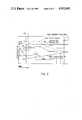
- FIG. 1is a block schematic diagram illustrating the principles of the present invention
- FIG. 2is a plot depicting the engine temperature input signal, an opposing compensating signal, and a resultant curve representing the compensated output signal, illustrating a typical application of the invention
- FIGS. 3A and 3Bmake up a detailed circuit diagram of the engine transient compensation circuit shown schematically in FIG. 1.
- a turbine engine 2is represented by the block at the left of the drawing.
- the engine 2may, for example, be a helicopter engine which occasionally approaches a high temperature known to be harmless for a short period of time, but which would cause an unnecessary overtemperature warning to be displayed on the cockpit temperature readout 34.
- Gas temperature sensors 4commonly thermocouples, sense the engine temperature and convert it into an electrical signal representing temperature. The temperature measured may be manifold gas temperature (MGT). This temperature signal is directed into the engine transient compensation circuit through electrical connections or couplings 5a, through terminals A, B, and C.
- the compensation circuitmay be mounted on a printed circuit board (as discussed below regarding FIG.
- a printed circuit boardit may be constructed according to principles and techniques well known in the industry, on which are mounted integrated circuits and/or standard components, available from various electronic component manufacturers.
- the engine temperature signal from thermocouplesis typically quite low, and by the use of an amplifier 6, the signal may be boosted to a level which permits reliable performance of the compensation circuit.
- This functionmay be implemented by Part No. MPS 312, an amplifier available from Micro Power Systems, or equivalent.
- Comparator 8monitors the amplified input signal and compares it to a reference voltage representing a precursor level of the harmless overtemperature transient, and when the input signal reaches this precursor level, the comparator changes state to initiate the generation of an opposing compensating signal by the balance of the circuit as described below.
- the precursor temperaturewould be approximately 782 ⁇ 3 degrees Centigrade.
- the function of comparator 8may be implemented by Part No. CA3260 from RCA, or equivalent.
- Plot 41A, 41Brepresents a typical harmless overtemperature transient which is labelled "MGT INPUT SIGNAL” where MGT stands for "manifold gas temperature”. Time is represented along the horizontal axis, and temperature is represented along the vertical axis in the plots of FIG. 2.
- comparator 12when the trip point is reached and comparator 8 changes state, a pulse forming network 10 is energized and generates a triggering pulse which is detected by comparator 12 which, in turn, changes state to generate an impulse which is applied to comparator analog switch 14 at terminal 13.
- the function of comparator 12may be implemented by Part No. CA3260 from RCA, or equivalent.
- the analog switch 14Prior to the generation of said triggering pulse by comparator 12, the analog switch 14 is in a ground state with no compensating signal being formed, so that until the trip point 40 is reached, the cockpit temperature readout 34 displays the true engine temperature.
- the switchcloses appropriate circuits to begin the charging of capacitor 16 from current source 22 which may be a current mirror, part no. 2N3811 from National, or an equivalent. While the capacitor 16 is being charged, it provides a signal which is routed by the analog switch through circuit 17, and amplifier 28 to point 32, and is applied to resistor 31 in opposition to the thermocouple signal through resistor 30 which scales the exact correction level.
- the signal from capacitor 16is summed with the signal from the thermocouple producing a reduced and compensated signal at point 32 which passes through the electrical connections 5b to the cockpit temperature readout 34.
- unity gain amplifiers 26 and 28couple the capacitor output to the intended compensation output point 32.
- Amplifiers 26 and 28may be implemented by Part No. CA1558, operational amplifiers available from RCA, or equivalents.
- Resistors 29, 30, 31 and 33may be varied depending upon system parameters. These parameters may vary according to the type of temperature sensors, thermocouples, circuit components, etc. Resistor 31 is normally very small, in order of one ohm, and resistor 30 would normally have a value of several thousand ohms. By choosing appropriate values for these resistors and other related components, the engine transient compensating circuit may be modified for use in a variety of engines operating over a broad range of conditions.
- Capacitor 16is charged for a relatively short period of time until the compensating signal generated by it reaches a predetermined maximum safe level. Using again the example of an LTS101 engine, this point is reached when the compensating signal reaches a level representing a temperature reduction of approximately 17° C. as displayed on the cockpit temperature readout 34. It takes approximately 15 ⁇ 2 seconds for this to happen. This point is shown up to dotted line 43 in FIG. 2. By choosing appropriate circuit components, the arrival at this point may be advanced or delayed, and the maximum temperature depression may be increased or decreased depending on the engine and its applications.
- Discharge comparator 18whose function can be performed by Part No. LM111 from National, or equivalent, monitors capcitor 16 output and compares it to a reference voltage. At the point at which the capacitor is providing the maximum desired compensating signal, comparator 18 signals the flip-flop or bistable circuit 20 and it in turn commands the analog switch 14 through terminal 15 to switch from the charging state to its discharge state. Upon receiving said command, the analog switch 14 opens and closes appropriate circuits, terminates the charging current from source 22 and provides a circuit path to current drain 24, allowing the capacitor 16 to be discharged at a predetermined rate.
- the function of current drain 24may be performed by Part No. 2N2920, a matched transistor available from National, or equivalent.
- the capacitor outputdecreases over time and generates a curve such as that shown at 42B in FIG. 2.
- This compensating current from the capacitoris combined with the temperature input signal 41B in FIG. 2, in the same manner as previously described. This results in the compensated signal 44B shown in FIG. 2, which is received by the cockpit display 34.
- Comparator 12performs a dual function, also monitoring the capacitor 16 output and comparing it to a reference. When the capacitor 16 is fully discharged, comparator 12 changes to its original state initiating another command to the analog switch 14 at input terminal 13. The analog switch 14 then switches to a state in which the capacitor 16 is electrically connected to ground. Comparator 12 also provides a reset command to the flip/flop 20 on lead 21 resetting it to its original state, and after these steps are accomplished, the analog switch 14 is ready to be reactivated when the need for an engine transient compensating signal is again required, providing that the temperature level drops below the reset level which is set by resistor 7 providing a temperature delay hystersis.
- Flip/flop 20may be Part No. CD4013 from National, or an equivalent.
- FIGS. 3a and 3btogether form a detailed circuit diagram of an illustrative embodiment of the subject invention.
- the dashed line around the circuitrepresents the boundary of a printed circuit board 35 which contains substantially the circuit represented in the diagram.
- Points E4 and E5represent electrical coupling terminals at which the circuit board 35 is connected to receive the signal representing engine temperature.
- Points E3 and E6are connections through which the compensated temperature signal is applied to the cockpit temperature readout 34, not shown in this figure.
- This particular embodimentoperates from a power supply of ⁇ 7.5 volts DC which is provided by an external power supply connected at points E1, E7, 55, 56, 57, and 58.
- the designation by the solid ground symbol in FIGS. 1 and 3represents signal ground. These points are connected to the power supply.
- Points labelled TPare test points used in calibrating the circuit for its particular application.
- Point E2is a connection to signal ground.
- current source 52(FIG. 3A) provides a constant current source for the differential amplifier 6 through resistor 54.
- Resistor 54is variable and can be set as desired to vary the trip point of the engine transient compensating circuit, depending upon the engine in use, operating conditions, safety factors, etc.
- Diode 50blocks the transmission of negative pulses.
- comparator 18(FIG. 3B) monitors the output potential of capacitor 16, and at the point when the capacitor 16 is providing the maximum desired compensating signal, comparator 18 changes state and initiates the discharge cycle of the capacitor 16. Comparator 18 determines this point by comparing capacitor 16 output with a reference potential which, in this embodiment, is the voltage level at the intersection of resistors 48 and 46 represented in FIG. 3B as summing point 47.
- comparator 12also monitors capacitor 16 output and signals the analog switch 14 to return to its ground state when comparator 12 senses that the capacitor has been fully discharged. This determination is made by comparing capacitor 16 output to a reference voltage determined at the intersection of resistors 59 and 60 at summing point 61.
- the analog switch as embodied in FIG. 3has four states: a charging state, a discharging state, an intermediate ground state, and a ground state.
- the analog switch 14At rest, before the engine transient compensating circuit is activated, the analog switch 14 is in its ground state, with switches 62 and 66 closed and the balance open, which grounds capacitor 16 through resistor 53 to signal ground.
- comparator 12When the trip point is reached, which in the previous example was approximately 782° C., comparator 12 changes state and commands the analog switch 14 to change from its ground state to its charging state. At that point, switches 64 and 68 are closed and the balance are opened. This connects capacitor 16 to current source 22, and provides a circuit path for the capacitor's compensating signal to flow through unity gain amplifiers 26 and 28 to the compensation point 32.
- discharge comparator 18When discharge comparator 18 senses that capacitor 16 is sufficiently charged to provide the maximum desired compensating signal, it commands the flip/flop 20 to reset analog switch 14 through terminal 15, closing switches 65 and 69 and opening the rest of the switches. This provides a circuit path by which capacitor 16 is discharged through switch 65 into current drain 24, but at the same time maintains a signal path through switch 69 for the compensating signal at the output of capacitor 16 through unity gain amplifier 26 into the balance of the circuit to the point 32.
- comparator 12When comparator 12 senses that capacitor 16 is fully discharged, it transmits a pulse to analog switch 14 through terminal 13 which causes it to change to its intermediate ground state by closing switches 63 and 67 and opening the rest. This connects capacitor 16 to signal ground through resistor 53 and also grounds the balance of the circuit.
- Flip/flop control 20has not yet been reset to its ground or ready position, and this is accomplished by command from comparator 12.
- the flip/flop 20is reset, but in so doing, it sends another command to analog switch 14 through terminal 15.
- This final command in the cyclecloses switches 62 and 66 opening the balance of the switching circuits, and the analog switch 14 is back to its ground state ready to be reactivated as necessary.
- a safety systemhas been incorporated into this embodiment of the invention to prevent a too-rapid reinitiation of the engine transient compensating circuit, unless the engine 2 has cooled down to a predetermined safe temperature.
- an hysteresis circuithas been provided to prevent comparator 8 from returning to its original state unless the engine temperature drops below the predetermined safe level.
- the hysteresis circuitincludes resistors 7 and 11, and differential amplifier 6.
- the "plus” input to comparator 8is at a more negative potential than the "minus” input, in part because the emitter resistor of transistor 6-A is reater than that of its paired transistor 6-B in the differential amplifier.
- the comparator 8will change state and shift to a positive output. This applies a positive voltage to resistor 11 which is fed back through resistor 7 to the emitter of transistor 6-B, thereby lowering the resetting temperature at which the "plus” input to comparator circuit 8 drops below the "minus” input, by the desired number of degrees.
- Resistor 11is a variable resistor which allows the hysteresis to be varied by approximately 20 degrees centigrade after the circuit is initially calibrated. Therefore, unless the safe temperature is reached, the engine transient compensating circuit will not operate and the cockpit temperature readout 34 will register true temperature and provide a warning if an overtemperature condition is reached. In the case of the LTS 101 engine used as an example previously, this temperature may be approximately 740° C.
Landscapes
- Engineering & Computer Science (AREA)
- Physics & Mathematics (AREA)
- General Physics & Mathematics (AREA)
- Mechanical Engineering (AREA)
- General Engineering & Computer Science (AREA)
- Combined Controls Of Internal Combustion Engines (AREA)
Abstract
Description
Claims (14)
Priority Applications (1)
| Application Number | Priority Date | Filing Date | Title |
|---|---|---|---|
| US06/357,587US4502043A (en) | 1982-03-12 | 1982-03-12 | Engine temperature transient compensating circuit |
Applications Claiming Priority (1)
| Application Number | Priority Date | Filing Date | Title |
|---|---|---|---|
| US06/357,587US4502043A (en) | 1982-03-12 | 1982-03-12 | Engine temperature transient compensating circuit |
Publications (1)
| Publication Number | Publication Date |
|---|---|
| US4502043Atrue US4502043A (en) | 1985-02-26 |
Family
ID=23406230
Family Applications (1)
| Application Number | Title | Priority Date | Filing Date |
|---|---|---|---|
| US06/357,587Expired - Fee RelatedUS4502043A (en) | 1982-03-12 | 1982-03-12 | Engine temperature transient compensating circuit |
Country Status (1)
| Country | Link |
|---|---|
| US (1) | US4502043A (en) |
Cited By (13)
| Publication number | Priority date | Publication date | Assignee | Title |
|---|---|---|---|---|
| FR2576413A1 (en)* | 1985-01-24 | 1986-07-25 | Mtu Muenchen Gmbh | DEVICE FOR MEASURING PRESSURES IN ROTARY SYSTEMS |
| US4740671A (en)* | 1983-06-07 | 1988-04-26 | Canon Kabushiki Kaisha | Temperature control apparatus for detecting an abnormality in a heater in a copying machine or the like |
| US5080496A (en)* | 1990-06-25 | 1992-01-14 | General Electric Company | Method and apparatus for compensated temperature prediction |
| US5479350A (en)* | 1993-08-23 | 1995-12-26 | B&D Instruments And Avionics, Inc. | Exhaust gas temperature indicator for a gas turbine engine |
| US6439767B1 (en)* | 1999-09-17 | 2002-08-27 | General Electric Company | Engine thrust bearing condition monitoring system and method |
| US6522990B1 (en)* | 1999-12-03 | 2003-02-18 | General Electric Company | Methods and apparatus for reducing temperature overshoot |
| US20050075779A1 (en)* | 2003-10-06 | 2005-04-07 | Read Michael J. | Engine transient detection and control strategy |
| US7654736B1 (en)* | 2006-04-19 | 2010-02-02 | Darryl Walker | Semiconductor device having variable parameter selection based on temperature and test method |
| US20110044119A1 (en)* | 2006-04-19 | 2011-02-24 | Walker Darryl G | Semiconductor Device having variable parameter selection based on temperature and test method |
| US9194754B2 (en) | 2014-03-28 | 2015-11-24 | Darryl G. Walker | Power up of semiconductor device having a temperature circuit and method therefor |
| US9286991B1 (en) | 2015-02-17 | 2016-03-15 | Darryl G. Walker | Multi-chip non-volatile semiconductor memory package including heater and sensor elements |
| US9284890B2 (en) | 2010-02-12 | 2016-03-15 | Siemens Aktiengesellschaft | Method of determining a combustor exit temperature and method of controlling a gas turbine |
| US9645191B2 (en) | 2014-08-20 | 2017-05-09 | Darryl G. Walker | Testing and setting performance parameters in a semiconductor device and method therefor |
Citations (5)
| Publication number | Priority date | Publication date | Assignee | Title |
|---|---|---|---|---|
| US3035443A (en)* | 1958-04-11 | 1962-05-22 | Arthur I Gray | Condition monitoring device |
| US3277458A (en)* | 1963-06-26 | 1966-10-04 | Thomas L Greenwood | Condition and condition duration indicator |
| US3931619A (en)* | 1970-09-14 | 1976-01-06 | Manuel S. Moore | Overtemperature monitor and integrator apparatus |
| US3946364A (en)* | 1975-01-08 | 1976-03-23 | Eldec Corporation | Method and apparatus for sensing, storing, and graphically displaying over-temperature conditions of jet engines |
| US4315296A (en)* | 1980-10-14 | 1982-02-09 | Semco Instruments, Inc. | Reliable over-temperature control circuit |
- 1982
- 1982-03-12USUS06/357,587patent/US4502043A/ennot_activeExpired - Fee Related
Patent Citations (5)
| Publication number | Priority date | Publication date | Assignee | Title |
|---|---|---|---|---|
| US3035443A (en)* | 1958-04-11 | 1962-05-22 | Arthur I Gray | Condition monitoring device |
| US3277458A (en)* | 1963-06-26 | 1966-10-04 | Thomas L Greenwood | Condition and condition duration indicator |
| US3931619A (en)* | 1970-09-14 | 1976-01-06 | Manuel S. Moore | Overtemperature monitor and integrator apparatus |
| US3946364A (en)* | 1975-01-08 | 1976-03-23 | Eldec Corporation | Method and apparatus for sensing, storing, and graphically displaying over-temperature conditions of jet engines |
| US4315296A (en)* | 1980-10-14 | 1982-02-09 | Semco Instruments, Inc. | Reliable over-temperature control circuit |
Cited By (36)
| Publication number | Priority date | Publication date | Assignee | Title |
|---|---|---|---|---|
| US4740671A (en)* | 1983-06-07 | 1988-04-26 | Canon Kabushiki Kaisha | Temperature control apparatus for detecting an abnormality in a heater in a copying machine or the like |
| FR2576413A1 (en)* | 1985-01-24 | 1986-07-25 | Mtu Muenchen Gmbh | DEVICE FOR MEASURING PRESSURES IN ROTARY SYSTEMS |
| US4703326A (en)* | 1985-01-24 | 1987-10-27 | Mtu Motoren-Und Turbinen-Union Munchen Gmbh | Method and apparatus for measuring pressures in a rotor of a turbomachine |
| US5080496A (en)* | 1990-06-25 | 1992-01-14 | General Electric Company | Method and apparatus for compensated temperature prediction |
| US5479350A (en)* | 1993-08-23 | 1995-12-26 | B&D Instruments And Avionics, Inc. | Exhaust gas temperature indicator for a gas turbine engine |
| US6439767B1 (en)* | 1999-09-17 | 2002-08-27 | General Electric Company | Engine thrust bearing condition monitoring system and method |
| US6637932B2 (en)* | 1999-09-17 | 2003-10-28 | General Electric Company | Engine thrust bearing condition monitoring method |
| US6522990B1 (en)* | 1999-12-03 | 2003-02-18 | General Electric Company | Methods and apparatus for reducing temperature overshoot |
| US20050075779A1 (en)* | 2003-10-06 | 2005-04-07 | Read Michael J. | Engine transient detection and control strategy |
| US6934619B2 (en) | 2003-10-06 | 2005-08-23 | International Engine Intellectual Property Company, Llc | Engine transient detection and control strategy |
| US8081532B2 (en) | 2006-04-19 | 2011-12-20 | Intellectual Ventures Holding 83 LLC | Semiconductor device having variable parameter selection based on temperature and test method |
| US8049145B1 (en) | 2006-04-19 | 2011-11-01 | Agerson Rall Group, L.L.C. | Semiconductor device having variable parameter selection based on temperature and test method |
| US20110044372A1 (en)* | 2006-04-19 | 2011-02-24 | Walker Darryl G | Semiconductor Device having variable parameter selection based on temperature and test method |
| US20110044119A1 (en)* | 2006-04-19 | 2011-02-24 | Walker Darryl G | Semiconductor Device having variable parameter selection based on temperature and test method |
| US20110046912A1 (en)* | 2006-04-19 | 2011-02-24 | Walker Darryl G | Semiconductor Device having variable parameter selection based on temperature and test method |
| US7953573B2 (en) | 2006-04-19 | 2011-05-31 | Agersonn Rall Group, L.L.C. | Semiconductor device having variable parameter selection based on temperature and test method |
| US8040742B2 (en) | 2006-04-19 | 2011-10-18 | Agersonn Rall Group, L.L.C. | Semiconductor device having variable parameter selection based on temperature and test method |
| US9766135B2 (en) | 2006-04-19 | 2017-09-19 | Nytell Software LLC | Semiconductor device having variable parameter selection based on temperature and test method |
| US7654736B1 (en)* | 2006-04-19 | 2010-02-02 | Darryl Walker | Semiconductor device having variable parameter selection based on temperature and test method |
| US8308359B2 (en) | 2006-04-19 | 2012-11-13 | Intellectual Ventures Holding 83 LLC | Semiconductor device having variable parameter selection based on temperature and test method |
| US8497453B2 (en) | 2006-04-19 | 2013-07-30 | Intellectual Ventures Holding 83 LLC | Semiconductor device having variable parameter selection based on temperature |
| US10656028B2 (en) | 2006-04-19 | 2020-05-19 | Samsung Electronics Co., Ltd. | Semiconductor device having variable parameter selection based on temperature and test method |
| US20110044118A1 (en)* | 2006-04-19 | 2011-02-24 | Walker Darryl G | Semiconductor Device having variable parameter selection based on temperature and test method |
| US9284890B2 (en) | 2010-02-12 | 2016-03-15 | Siemens Aktiengesellschaft | Method of determining a combustor exit temperature and method of controlling a gas turbine |
| US9772232B2 (en) | 2014-03-28 | 2017-09-26 | Darryl G. Walker | Semiconductor device having temperature sensor circuit that detects a temperature range upper limit value and a temperature range lower limit value |
| US9274007B2 (en) | 2014-03-28 | 2016-03-01 | Darryl G. Walker | Semiconductor device having temperature sensor circuits |
| US9810585B2 (en) | 2014-03-28 | 2017-11-07 | Darryl G. Walker | Semiconductor device having a temperature circuit that provides a plurality of temperature operating ranges |
| US9939330B2 (en) | 2014-03-28 | 2018-04-10 | Darryl G. Walker | Semiconductor device having subthreshold operating circuits including a back body bias potential based on temperature range |
| US9194754B2 (en) | 2014-03-28 | 2015-11-24 | Darryl G. Walker | Power up of semiconductor device having a temperature circuit and method therefor |
| US9645191B2 (en) | 2014-08-20 | 2017-05-09 | Darryl G. Walker | Testing and setting performance parameters in a semiconductor device and method therefor |
| US9658277B2 (en) | 2014-08-20 | 2017-05-23 | Darryl G. Walker | Testing and setting performance parameters in a semiconductor device and method therefor |
| US10006959B2 (en) | 2014-08-20 | 2018-06-26 | Darryl G. Walker | Testing and setting performance parameters in a semiconductor device and method therefor |
| US9613719B1 (en) | 2015-02-17 | 2017-04-04 | Darryl G. Walker | Multi-chip non-volatile semiconductor memory package including heater and sensor elements |
| US9286991B1 (en) | 2015-02-17 | 2016-03-15 | Darryl G. Walker | Multi-chip non-volatile semiconductor memory package including heater and sensor elements |
| US9928925B1 (en) | 2015-02-17 | 2018-03-27 | Darryl G. Walker | Multi-chip non-volatile semiconductor memory package including heater and sensor elements |
| US10141058B1 (en) | 2015-02-17 | 2018-11-27 | Darryl G. Walker | Multi-chip non-volatile semiconductor memory package including heater and sensor elements |
Similar Documents
| Publication | Publication Date | Title |
|---|---|---|
| US4502043A (en) | Engine temperature transient compensating circuit | |
| US5062294A (en) | Apparatus for detecting pressure in cylinder of internal combustion engine | |
| US4058975A (en) | Gas turbine temperature sensor validation apparatus and method | |
| US3931619A (en) | Overtemperature monitor and integrator apparatus | |
| WO1990015314A1 (en) | Thermocouple transmitter with cold junction compensation | |
| US4873484A (en) | Extended range composite head power sensor with three circuit branches having a common node | |
| US4179745A (en) | Thermocouple linearizer circuit | |
| US4057206A (en) | Ejection sequencing system with airspeed and altitude sensing | |
| US4218916A (en) | Digital thermometer modification for telemetry and analog recording | |
| US3038106A (en) | Electrical network automatically responsive to a change in condition | |
| US4922230A (en) | Fire discriminating apparatus | |
| KR100422889B1 (en) | Pressure transducer, in particular for sensing a lateral collision in a motor vehicle | |
| US3775745A (en) | Engine over-temperature warning system | |
| EP0244501B1 (en) | Temperature sensing circuit | |
| EP0352987B1 (en) | Solid state circuit protector | |
| US3972237A (en) | Electronic thermometer | |
| US3990308A (en) | Temperature measurement system for free turbine type gas turbine engines | |
| US4638850A (en) | Electronic thermostat | |
| US4851954A (en) | Monitoring apparatus for monitoring temperature in a circuit arrangement | |
| US4315296A (en) | Reliable over-temperature control circuit | |
| US3509768A (en) | Turbine inlet average temperature system | |
| US4117670A (en) | Dual slope temperature differential shutdown control for gas turbines | |
| GB1375389A (en) | ||
| US3890832A (en) | Engine torque monitoring system | |
| US3808882A (en) | Engine torque control system |
Legal Events
| Date | Code | Title | Description |
|---|---|---|---|
| AS | Assignment | Owner name:SEMCO INSTRUMENTS, INC., NORTH HOLLYWOOD, CA. A Free format text:ASSIGNMENT OF ASSIGNORS INTEREST.;ASSIGNOR:MOORE, M. SAMUEL;REEL/FRAME:003978/0853 Effective date:19820224 | |
| FEPP | Fee payment procedure | Free format text:PAYOR NUMBER ASSIGNED (ORIGINAL EVENT CODE: ASPN); ENTITY STATUS OF PATENT OWNER: SMALL ENTITY | |
| FPAY | Fee payment | Year of fee payment:4 | |
| REMI | Maintenance fee reminder mailed | ||
| LAPS | Lapse for failure to pay maintenance fees | ||
| FP | Lapsed due to failure to pay maintenance fee | Effective date:19930228 | |
| STCH | Information on status: patent discontinuation | Free format text:PATENT EXPIRED DUE TO NONPAYMENT OF MAINTENANCE FEES UNDER 37 CFR 1.362 | |
| AS | Assignment | Owner name:THE BANK OF NEW YORK MELLON TRUST COMPANY, N.A.,, Free format text:SECURITY INTEREST;ASSIGNORS:TRANSDIGM, INC.;ADAMS RITE AEROSPACE, INC.;AEROCONTROLEX GROUP, INC.;AND OTHERS;REEL/FRAME:048365/0499 Effective date:20190214 | |
| AS | Assignment | Owner name:THE BANK OF NEW YORK MELLON TRUST COMPANY, N.A., AS TRUSTEE AND NOTES COLLATERAL AGENT, ILLINOIS Free format text:PATENT SECURITY AGREEMENT;ASSIGNORS:AIRBORNE SYSTEMS NORTH AMERICA OF NJ INC.;ACME AEROSPACE, INC.;ADAMS RITE AEROSPACE, INC.;AND OTHERS;REEL/FRAME:052352/0704 Effective date:20200408 | |
| AS | Assignment | Owner name:APICAL INDUSTRIES, INC., OHIO Free format text:RELEASE BY SECURED PARTY;ASSIGNOR:THE BANK OF NEW YORK MELLON TRUST COMPANY, N.A., AS TRUSTEE;REEL/FRAME:063363/0753 Effective date:20230410 Owner name:SIMPLEX MANUFACTURING CO., OHIO Free format text:RELEASE BY SECURED PARTY;ASSIGNOR:THE BANK OF NEW YORK MELLON TRUST COMPANY, N.A., AS TRUSTEE;REEL/FRAME:063363/0753 Effective date:20230410 Owner name:CHELTON, INC. (N/K/A CHELTON AVIONICS, INC.), ARIZONA Free format text:RELEASE BY SECURED PARTY;ASSIGNOR:THE BANK OF NEW YORK MELLON TRUST COMPANY, N.A., AS TRUSTEE;REEL/FRAME:063363/0753 Effective date:20230410 Owner name:PALOMAR PRODUCTS, INC., CALIFORNIA Free format text:RELEASE BY SECURED PARTY;ASSIGNOR:THE BANK OF NEW YORK MELLON TRUST COMPANY, N.A., AS TRUSTEE;REEL/FRAME:063363/0753 Effective date:20230410 Owner name:KORRY ELECTRONICS CO., WASHINGTON Free format text:RELEASE BY SECURED PARTY;ASSIGNOR:THE BANK OF NEW YORK MELLON TRUST COMPANY, N.A., AS TRUSTEE;REEL/FRAME:063363/0753 Effective date:20230410 Owner name:MASON ELECTRIC CO., CALIFORNIA Free format text:RELEASE BY SECURED PARTY;ASSIGNOR:THE BANK OF NEW YORK MELLON TRUST COMPANY, N.A., AS TRUSTEE;REEL/FRAME:063363/0753 Effective date:20230410 Owner name:TA AEROSPACE CO., CALIFORNIA Free format text:RELEASE BY SECURED PARTY;ASSIGNOR:THE BANK OF NEW YORK MELLON TRUST COMPANY, N.A., AS TRUSTEE;REEL/FRAME:063363/0753 Effective date:20230410 Owner name:NMC GROUP INC., CALIFORNIA Free format text:RELEASE BY SECURED PARTY;ASSIGNOR:THE BANK OF NEW YORK MELLON TRUST COMPANY, N.A., AS TRUSTEE;REEL/FRAME:063363/0753 Effective date:20230410 Owner name:LEACH INTERNATIONAL CORPORATION, CALIFORNIA Free format text:RELEASE BY SECURED PARTY;ASSIGNOR:THE BANK OF NEW YORK MELLON TRUST COMPANY, N.A., AS TRUSTEE;REEL/FRAME:063363/0753 Effective date:20230410 Owner name:ARMTEC DEFENSE PRODUCTS COMPANY, CALIFORNIA Free format text:RELEASE BY SECURED PARTY;ASSIGNOR:THE BANK OF NEW YORK MELLON TRUST COMPANY, N.A., AS TRUSTEE;REEL/FRAME:063363/0753 Effective date:20230410 Owner name:ARMTEC COUNTERMEASURES CO., NORTH CAROLINA Free format text:RELEASE BY SECURED PARTY;ASSIGNOR:THE BANK OF NEW YORK MELLON TRUST COMPANY, N.A., AS TRUSTEE;REEL/FRAME:063363/0753 Effective date:20230410 Owner name:YOUNG & FRANKLIN INC., NEW YORK Free format text:RELEASE BY SECURED PARTY;ASSIGNOR:THE BANK OF NEW YORK MELLON TRUST COMPANY, N.A., AS TRUSTEE;REEL/FRAME:063363/0753 Effective date:20230410 Owner name:WHIPPANY ACTUATION SYSTEMS, LLC, NEW JERSEY Free format text:RELEASE BY SECURED PARTY;ASSIGNOR:THE BANK OF NEW YORK MELLON TRUST COMPANY, N.A., AS TRUSTEE;REEL/FRAME:063363/0753 Effective date:20230410 Owner name:WESTERN SKY INDUSTRIES, LLC, KENTUCKY Free format text:RELEASE BY SECURED PARTY;ASSIGNOR:THE BANK OF NEW YORK MELLON TRUST COMPANY, N.A., AS TRUSTEE;REEL/FRAME:063363/0753 Effective date:20230410 Owner name:TRANSCOIL LLC, PENNSYLVANIA Free format text:RELEASE BY SECURED PARTY;ASSIGNOR:THE BANK OF NEW YORK MELLON TRUST COMPANY, N.A., AS TRUSTEE;REEL/FRAME:063363/0753 Effective date:20230410 Owner name:TELAIR INTERNATIONAL LLC, NEW YORK Free format text:RELEASE BY SECURED PARTY;ASSIGNOR:THE BANK OF NEW YORK MELLON TRUST COMPANY, N.A., AS TRUSTEE;REEL/FRAME:063363/0753 Effective date:20230410 Owner name:TEAC AEROSPACE TECHNOLOGIES, INC., FLORIDA Free format text:RELEASE BY SECURED PARTY;ASSIGNOR:THE BANK OF NEW YORK MELLON TRUST COMPANY, N.A., AS TRUSTEE;REEL/FRAME:063363/0753 Effective date:20230410 Owner name:TACTAIR FLUID CONTROLS INC., NEW YORK Free format text:RELEASE BY SECURED PARTY;ASSIGNOR:THE BANK OF NEW YORK MELLON TRUST COMPANY, N.A., AS TRUSTEE;REEL/FRAME:063363/0753 Effective date:20230410 Owner name:SHIELD RESTRAINT SYSTEMS, INC., INDIANA Free format text:RELEASE BY SECURED PARTY;ASSIGNOR:THE BANK OF NEW YORK MELLON TRUST COMPANY, N.A., AS TRUSTEE;REEL/FRAME:063363/0753 Effective date:20230410 Owner name:SEMCO INSTRUMENTS, INC., CONNECTICUT Free format text:RELEASE BY SECURED PARTY;ASSIGNOR:THE BANK OF NEW YORK MELLON TRUST COMPANY, N.A., AS TRUSTEE;REEL/FRAME:063363/0753 Effective date:20230410 Owner name:SCHNELLER LLC, OHIO Free format text:RELEASE BY SECURED PARTY;ASSIGNOR:THE BANK OF NEW YORK MELLON TRUST COMPANY, N.A., AS TRUSTEE;REEL/FRAME:063363/0753 Effective date:20230410 Owner name:PNEUDRAULICS, INC., CALIFORNIA Free format text:RELEASE BY SECURED PARTY;ASSIGNOR:THE BANK OF NEW YORK MELLON TRUST COMPANY, N.A., AS TRUSTEE;REEL/FRAME:063363/0753 Effective date:20230410 Owner name:PEXCO AEROSPACE, INC., WASHINGTON Free format text:RELEASE BY SECURED PARTY;ASSIGNOR:THE BANK OF NEW YORK MELLON TRUST COMPANY, N.A., AS TRUSTEE;REEL/FRAME:063363/0753 Effective date:20230410 Owner name:MARATHONNORCO AEROSPACE, INC., TEXAS Free format text:RELEASE BY SECURED PARTY;ASSIGNOR:THE BANK OF NEW YORK MELLON TRUST COMPANY, N.A., AS TRUSTEE;REEL/FRAME:063363/0753 Effective date:20230410 Owner name:HARTWELL CORPORATION, CALIFORNIA Free format text:RELEASE BY SECURED PARTY;ASSIGNOR:THE BANK OF NEW YORK MELLON TRUST COMPANY, N.A., AS TRUSTEE;REEL/FRAME:063363/0753 Effective date:20230410 Owner name:HARCO LLC, CONNECTICUT Free format text:RELEASE BY SECURED PARTY;ASSIGNOR:THE BANK OF NEW YORK MELLON TRUST COMPANY, N.A., AS TRUSTEE;REEL/FRAME:063363/0753 Effective date:20230410 Owner name:HARCO LABORATORIES, INC., CONNECTICUT Free format text:RELEASE BY SECURED PARTY;ASSIGNOR:THE BANK OF NEW YORK MELLON TRUST COMPANY, N.A., AS TRUSTEE;REEL/FRAME:063363/0753 Effective date:20230410 Owner name:ELECTROMECH TECHNOLOGIES LLC, KANSAS Free format text:RELEASE BY SECURED PARTY;ASSIGNOR:THE BANK OF NEW YORK MELLON TRUST COMPANY, N.A., AS TRUSTEE;REEL/FRAME:063363/0753 Effective date:20230410 Owner name:DUKES AEROSPACE, INC., OHIO Free format text:RELEASE BY SECURED PARTY;ASSIGNOR:THE BANK OF NEW YORK MELLON TRUST COMPANY, N.A., AS TRUSTEE;REEL/FRAME:063363/0753 Effective date:20230410 Owner name:DATA DEVICE CORPORATION, NEW YORK Free format text:RELEASE BY SECURED PARTY;ASSIGNOR:THE BANK OF NEW YORK MELLON TRUST COMPANY, N.A., AS TRUSTEE;REEL/FRAME:063363/0753 Effective date:20230410 Owner name:CHAMPION AEROSPACE LLC, SOUTH CAROLINA Free format text:RELEASE BY SECURED PARTY;ASSIGNOR:THE BANK OF NEW YORK MELLON TRUST COMPANY, N.A., AS TRUSTEE;REEL/FRAME:063363/0753 Effective date:20230410 Owner name:CEF INDUSTRIES, INC., ILLINOIS Free format text:RELEASE BY SECURED PARTY;ASSIGNOR:THE BANK OF NEW YORK MELLON TRUST COMPANY, N.A., AS TRUSTEE;REEL/FRAME:063363/0753 Effective date:20230410 Owner name:BRUCE AEROSPACE, INC., NEVADA Free format text:RELEASE BY SECURED PARTY;ASSIGNOR:THE BANK OF NEW YORK MELLON TRUST COMPANY, N.A., AS TRUSTEE;REEL/FRAME:063363/0753 Effective date:20230410 Owner name:BREEZE EASTERN CORPORATION, NEW JERSEY Free format text:RELEASE BY SECURED PARTY;ASSIGNOR:THE BANK OF NEW YORK MELLON TRUST COMPANY, N.A., AS TRUSTEE;REEL/FRAME:063363/0753 Effective date:20230410 Owner name:BEAM'S INDUSTRIES, OKLAHOMA Free format text:RELEASE BY SECURED PARTY;ASSIGNOR:THE BANK OF NEW YORK MELLON TRUST COMPANY, N.A., AS TRUSTEE;REEL/FRAME:063363/0753 Effective date:20230410 Owner name:AVTECH TYEE, INC., WASHINGTON Free format text:RELEASE BY SECURED PARTY;ASSIGNOR:THE BANK OF NEW YORK MELLON TRUST COMPANY, N.A., AS TRUSTEE;REEL/FRAME:063363/0753 Effective date:20230410 Owner name:AVIONICS SPECIALTIES, INC., OHIO Free format text:RELEASE BY SECURED PARTY;ASSIGNOR:THE BANK OF NEW YORK MELLON TRUST COMPANY, N.A., AS TRUSTEE;REEL/FRAME:063363/0753 Effective date:20230410 Owner name:AVIONIC INSTRUMENTS LLC, NEW JERSEY Free format text:RELEASE BY SECURED PARTY;ASSIGNOR:THE BANK OF NEW YORK MELLON TRUST COMPANY, N.A., AS TRUSTEE;REEL/FRAME:063363/0753 Effective date:20230410 Owner name:ARKWIN INDUSTRIES, INC., NEW YORK Free format text:RELEASE BY SECURED PARTY;ASSIGNOR:THE BANK OF NEW YORK MELLON TRUST COMPANY, N.A., AS TRUSTEE;REEL/FRAME:063363/0753 Effective date:20230410 Owner name:AMSAFE, INC., ARIZONA Free format text:RELEASE BY SECURED PARTY;ASSIGNOR:THE BANK OF NEW YORK MELLON TRUST COMPANY, N.A., AS TRUSTEE;REEL/FRAME:063363/0753 Effective date:20230410 Owner name:AMSAFE COMMERCIAL PRODUCTS INC., INDIANA Free format text:RELEASE BY SECURED PARTY;ASSIGNOR:THE BANK OF NEW YORK MELLON TRUST COMPANY, N.A., AS TRUSTEE;REEL/FRAME:063363/0753 Effective date:20230410 Owner name:AIRBORNE SYSTEMS NORTH AMERICA OF NJ INC., NEW JERSEY Free format text:RELEASE BY SECURED PARTY;ASSIGNOR:THE BANK OF NEW YORK MELLON TRUST COMPANY, N.A., AS TRUSTEE;REEL/FRAME:063363/0753 Effective date:20230410 Owner name:AIRBORNE HOLDINGS, INC., OHIO Free format text:RELEASE BY SECURED PARTY;ASSIGNOR:THE BANK OF NEW YORK MELLON TRUST COMPANY, N.A., AS TRUSTEE;REEL/FRAME:063363/0753 Effective date:20230410 Owner name:AEROSONIC CORPORATION, FLORIDA Free format text:RELEASE BY SECURED PARTY;ASSIGNOR:THE BANK OF NEW YORK MELLON TRUST COMPANY, N.A., AS TRUSTEE;REEL/FRAME:063363/0753 Effective date:20230410 Owner name:AEROCONTROLEX GROUP, INC., OHIO Free format text:RELEASE BY SECURED PARTY;ASSIGNOR:THE BANK OF NEW YORK MELLON TRUST COMPANY, N.A., AS TRUSTEE;REEL/FRAME:063363/0753 Effective date:20230410 Owner name:ADAMS RITE AEROSPACE, INC., CALIFORNIA Free format text:RELEASE BY SECURED PARTY;ASSIGNOR:THE BANK OF NEW YORK MELLON TRUST COMPANY, N.A., AS TRUSTEE;REEL/FRAME:063363/0753 Effective date:20230410 Owner name:ACME AEROSPACE, INC., ARIZONA Free format text:RELEASE BY SECURED PARTY;ASSIGNOR:THE BANK OF NEW YORK MELLON TRUST COMPANY, N.A., AS TRUSTEE;REEL/FRAME:063363/0753 Effective date:20230410 Owner name:TRANSDIGM GROUP INCORPORATED, OHIO Free format text:RELEASE BY SECURED PARTY;ASSIGNOR:THE BANK OF NEW YORK MELLON TRUST COMPANY, N.A., AS TRUSTEE;REEL/FRAME:063363/0753 Effective date:20230410 Owner name:TRANSDIGM, INC., OHIO Free format text:RELEASE BY SECURED PARTY;ASSIGNOR:THE BANK OF NEW YORK MELLON TRUST COMPANY, N.A., AS TRUSTEE;REEL/FRAME:063363/0753 Effective date:20230410 | |
| AS | Assignment | Owner name:CEF INDUSTRIES, INC., ILLINOIS Free format text:RELEASE OF PATENT SECURITY AGREEMENT RECORDED FEBRUARY 19, 2019 AT REEL/FRAME 048365/0499;ASSIGNOR:THE BANK OF NEW YORK MELLON TRUST COMPANY, N.A., AS TRUSTEE;REEL/FRAME:067640/0147 Effective date:20240514 Owner name:SCHNELLER, INC., OHIO Free format text:RELEASE OF PATENT SECURITY AGREEMENT RECORDED FEBRUARY 19, 2019 AT REEL/FRAME 048365/0499;ASSIGNOR:THE BANK OF NEW YORK MELLON TRUST COMPANY, N.A., AS TRUSTEE;REEL/FRAME:067640/0147 Effective date:20240514 Owner name:ACME AEROSPACE, INC., ARIZONA Free format text:RELEASE OF PATENT SECURITY AGREEMENT RECORDED FEBRUARY 19, 2019 AT REEL/FRAME 048365/0499;ASSIGNOR:THE BANK OF NEW YORK MELLON TRUST COMPANY, N.A., AS TRUSTEE;REEL/FRAME:067640/0147 Effective date:20240514 Owner name:ADAMS RITE AEROSPACE, INC., CALIFORNIA Free format text:RELEASE OF PATENT SECURITY AGREEMENT RECORDED FEBRUARY 19, 2019 AT REEL/FRAME 048365/0499;ASSIGNOR:THE BANK OF NEW YORK MELLON TRUST COMPANY, N.A., AS TRUSTEE;REEL/FRAME:067640/0147 Effective date:20240514 Owner name:CALSPAN SYSTEMS, LLC, VIRGINIA Free format text:RELEASE OF PATENT SECURITY AGREEMENT RECORDED FEBRUARY 19, 2019 AT REEL/FRAME 048365/0499;ASSIGNOR:THE BANK OF NEW YORK MELLON TRUST COMPANY, N.A., AS TRUSTEE;REEL/FRAME:067640/0147 Effective date:20240514 Owner name:CALSPAN AERO SYSTEMS ENGINEERING, INC., MINNESOTA Free format text:RELEASE OF PATENT SECURITY AGREEMENT RECORDED FEBRUARY 19, 2019 AT REEL/FRAME 048365/0499;ASSIGNOR:THE BANK OF NEW YORK MELLON TRUST COMPANY, N.A., AS TRUSTEE;REEL/FRAME:067640/0147 Effective date:20240514 Owner name:TELAIR US LLC, NORTH CAROLINA Free format text:RELEASE OF PATENT SECURITY AGREEMENT RECORDED FEBRUARY 19, 2019 AT REEL/FRAME 048365/0499;ASSIGNOR:THE BANK OF NEW YORK MELLON TRUST COMPANY, N.A., AS TRUSTEE;REEL/FRAME:067640/0147 Effective date:20240514 Owner name:PEXCO AEROSPACE, INC., WASHINGTON Free format text:RELEASE OF PATENT SECURITY AGREEMENT RECORDED FEBRUARY 19, 2019 AT REEL/FRAME 048365/0499;ASSIGNOR:THE BANK OF NEW YORK MELLON TRUST COMPANY, N.A., AS TRUSTEE;REEL/FRAME:067640/0147 Effective date:20240514 Owner name:HARCO, LLC (N/K/A HARCOSEMCO LLC), CONNECTICUT Free format text:RELEASE OF PATENT SECURITY AGREEMENT RECORDED FEBRUARY 19, 2019 AT REEL/FRAME 048365/0499;ASSIGNOR:THE BANK OF NEW YORK MELLON TRUST COMPANY, N.A., AS TRUSTEE;REEL/FRAME:067640/0147 Effective date:20240514 Owner name:HARCOSEMCO LLC, CONNECTICUT Free format text:RELEASE OF PATENT SECURITY AGREEMENT RECORDED FEBRUARY 19, 2019 AT REEL/FRAME 048365/0499;ASSIGNOR:THE BANK OF NEW YORK MELLON TRUST COMPANY, N.A., AS TRUSTEE;REEL/FRAME:067640/0147 Effective date:20240514 Owner name:AIRBORNE SYSTEMS NA, INC., OHIO Free format text:RELEASE OF PATENT SECURITY AGREEMENT RECORDED FEBRUARY 19, 2019 AT REEL/FRAME 048365/0499;ASSIGNOR:THE BANK OF NEW YORK MELLON TRUST COMPANY, N.A., AS TRUSTEE;REEL/FRAME:067640/0147 Effective date:20240514 Owner name:AERO-INSTRUMENTS CO., LLC, OHIO Free format text:RELEASE OF PATENT SECURITY AGREEMENT RECORDED FEBRUARY 19, 2019 AT REEL/FRAME 048365/0499;ASSIGNOR:THE BANK OF NEW YORK MELLON TRUST COMPANY, N.A., AS TRUSTEE;REEL/FRAME:067640/0147 Effective date:20240514 Owner name:APICAL INDUSTRIES, INC., OHIO Free format text:RELEASE OF PATENT SECURITY AGREEMENT RECORDED FEBRUARY 19, 2019 AT REEL/FRAME 048365/0499;ASSIGNOR:THE BANK OF NEW YORK MELLON TRUST COMPANY, N.A., AS TRUSTEE;REEL/FRAME:067640/0147 Effective date:20240514 Owner name:SIMPLEX MANUFACTURING CO., OHIO Free format text:RELEASE OF PATENT SECURITY AGREEMENT RECORDED FEBRUARY 19, 2019 AT REEL/FRAME 048365/0499;ASSIGNOR:THE BANK OF NEW YORK MELLON TRUST COMPANY, N.A., AS TRUSTEE;REEL/FRAME:067640/0147 Effective date:20240514 Owner name:CHELTON, INC. (N/K/A CHELTON AVIONICS, INC.), ARIZONA Free format text:RELEASE OF PATENT SECURITY AGREEMENT RECORDED FEBRUARY 19, 2019 AT REEL/FRAME 048365/0499;ASSIGNOR:THE BANK OF NEW YORK MELLON TRUST COMPANY, N.A., AS TRUSTEE;REEL/FRAME:067640/0147 Effective date:20240514 Owner name:MEMTRON TECHNOLOGIES CO., MICHIGAN Free format text:RELEASE OF PATENT SECURITY AGREEMENT RECORDED FEBRUARY 19, 2019 AT REEL/FRAME 048365/0499;ASSIGNOR:THE BANK OF NEW YORK MELLON TRUST COMPANY, N.A., AS TRUSTEE;REEL/FRAME:067640/0147 Effective date:20240514 Owner name:ROLLS-ROYCE PLC, UNITED KINGDOM Free format text:RELEASE OF PATENT SECURITY AGREEMENT RECORDED FEBRUARY 19, 2019 AT REEL/FRAME 048365/0499;ASSIGNOR:THE BANK OF NEW YORK MELLON TRUST COMPANY, N.A., AS TRUSTEE;REEL/FRAME:067640/0147 Effective date:20240514 Owner name:PALOMAR PRODUCTS, INC., CALIFORNIA Free format text:RELEASE OF PATENT SECURITY AGREEMENT RECORDED FEBRUARY 19, 2019 AT REEL/FRAME 048365/0499;ASSIGNOR:THE BANK OF NEW YORK MELLON TRUST COMPANY, N.A., AS TRUSTEE;REEL/FRAME:067640/0147 Effective date:20240514 Owner name:KORRY ELECTRONICS CO., WASHINGTON Free format text:RELEASE OF PATENT SECURITY AGREEMENT RECORDED FEBRUARY 19, 2019 AT REEL/FRAME 048365/0499;ASSIGNOR:THE BANK OF NEW YORK MELLON TRUST COMPANY, N.A., AS TRUSTEE;REEL/FRAME:067640/0147 Effective date:20240514 Owner name:MASON ELECTRIC CO., CALIFORNIA Free format text:RELEASE OF PATENT SECURITY AGREEMENT RECORDED FEBRUARY 19, 2019 AT REEL/FRAME 048365/0499;ASSIGNOR:THE BANK OF NEW YORK MELLON TRUST COMPANY, N.A., AS TRUSTEE;REEL/FRAME:067640/0147 Effective date:20240514 Owner name:TA AEROSPACE CO., CALIFORNIA Free format text:RELEASE OF PATENT SECURITY AGREEMENT RECORDED FEBRUARY 19, 2019 AT REEL/FRAME 048365/0499;ASSIGNOR:THE BANK OF NEW YORK MELLON TRUST COMPANY, N.A., AS TRUSTEE;REEL/FRAME:067640/0147 Effective date:20240514 Owner name:NMC GROUP, INC., CALIFORNIA Free format text:RELEASE OF PATENT SECURITY AGREEMENT RECORDED FEBRUARY 19, 2019 AT REEL/FRAME 048365/0499;ASSIGNOR:THE BANK OF NEW YORK MELLON TRUST COMPANY, N.A., AS TRUSTEE;REEL/FRAME:067640/0147 Effective date:20240514 Owner name:SOURIAU USA, INC., PENNSYLVANIA Free format text:RELEASE OF PATENT SECURITY AGREEMENT RECORDED FEBRUARY 19, 2019 AT REEL/FRAME 048365/0499;ASSIGNOR:THE BANK OF NEW YORK MELLON TRUST COMPANY, N.A., AS TRUSTEE;REEL/FRAME:067640/0147 Effective date:20240514 Owner name:LEACH INTERNATIONAL CORPORATION, CALIFORNIA Free format text:RELEASE OF PATENT SECURITY AGREEMENT RECORDED FEBRUARY 19, 2019 AT REEL/FRAME 048365/0499;ASSIGNOR:THE BANK OF NEW YORK MELLON TRUST COMPANY, N.A., AS TRUSTEE;REEL/FRAME:067640/0147 Effective date:20240514 Owner name:JOSLYN SUNBANK COMPANY LLC, CALIFORNIA Free format text:RELEASE OF PATENT SECURITY AGREEMENT RECORDED FEBRUARY 19, 2019 AT REEL/FRAME 048365/0499;ASSIGNOR:THE BANK OF NEW YORK MELLON TRUST COMPANY, N.A., AS TRUSTEE;REEL/FRAME:067640/0147 Effective date:20240514 Owner name:ARMTEC DEFENSE PRODUCTS COMPANY, CALIFORNIA Free format text:RELEASE OF PATENT SECURITY AGREEMENT RECORDED FEBRUARY 19, 2019 AT REEL/FRAME 048365/0499;ASSIGNOR:THE BANK OF NEW YORK MELLON TRUST COMPANY, N.A., AS TRUSTEE;REEL/FRAME:067640/0147 Effective date:20240514 Owner name:ADVANCED INPUT DEVICES, INC., IDAHO Free format text:RELEASE OF PATENT SECURITY AGREEMENT RECORDED FEBRUARY 19, 2019 AT REEL/FRAME 048365/0499;ASSIGNOR:THE BANK OF NEW YORK MELLON TRUST COMPANY, N.A., AS TRUSTEE;REEL/FRAME:067640/0147 Effective date:20240514 Owner name:ARMTEC COUNTERMEASURES CO., NORTH CAROLINA Free format text:RELEASE OF PATENT SECURITY AGREEMENT RECORDED FEBRUARY 19, 2019 AT REEL/FRAME 048365/0499;ASSIGNOR:THE BANK OF NEW YORK MELLON TRUST COMPANY, N.A., AS TRUSTEE;REEL/FRAME:067640/0147 Effective date:20240514 Owner name:YOUNG & FRANKLIN INC., NEW YORK Free format text:RELEASE OF PATENT SECURITY AGREEMENT RECORDED FEBRUARY 19, 2019 AT REEL/FRAME 048365/0499;ASSIGNOR:THE BANK OF NEW YORK MELLON TRUST COMPANY, N.A., AS TRUSTEE;REEL/FRAME:067640/0147 Effective date:20240514 Owner name:WHIPPANY ACTUATION SYSTEMS, LLC, NEW JERSEY Free format text:RELEASE OF PATENT SECURITY AGREEMENT RECORDED FEBRUARY 19, 2019 AT REEL/FRAME 048365/0499;ASSIGNOR:THE BANK OF NEW YORK MELLON TRUST COMPANY, N.A., AS TRUSTEE;REEL/FRAME:067640/0147 Effective date:20240514 Owner name:SOUTHCO, INC., PENNSYLVANIA Free format text:RELEASE OF PATENT SECURITY AGREEMENT RECORDED FEBRUARY 19, 2019 AT REEL/FRAME 048365/0499;ASSIGNOR:THE BANK OF NEW YORK MELLON TRUST COMPANY, N.A., AS TRUSTEE;REEL/FRAME:067640/0147 Effective date:20240514 Owner name:TRANSICOIL INC., PENNSYLVANIA Free format text:RELEASE OF PATENT SECURITY AGREEMENT RECORDED FEBRUARY 19, 2019 AT REEL/FRAME 048365/0499;ASSIGNOR:THE BANK OF NEW YORK MELLON TRUST COMPANY, N.A., AS TRUSTEE;REEL/FRAME:067640/0147 Effective date:20240514 Owner name:AEROCONTROLEX GROUP, INC., OHIO Free format text:RELEASE OF PATENT SECURITY AGREEMENT RECORDED FEBRUARY 19, 2019 AT REEL/FRAME 048365/0499;ASSIGNOR:THE BANK OF NEW YORK MELLON TRUST COMPANY, N.A., AS TRUSTEE;REEL/FRAME:067640/0147 Effective date:20240514 Owner name:TURNTIME TECHNOLOGIES AB, SWEDEN Free format text:RELEASE OF PATENT SECURITY AGREEMENT RECORDED FEBRUARY 19, 2019 AT REEL/FRAME 048365/0499;ASSIGNOR:THE BANK OF NEW YORK MELLON TRUST COMPANY, N.A., AS TRUSTEE;REEL/FRAME:067640/0147 Effective date:20240514 Owner name:NORDISK AVIATION PRODUCTS AS, NORWAY Free format text:RELEASE OF PATENT SECURITY AGREEMENT RECORDED FEBRUARY 19, 2019 AT REEL/FRAME 048365/0499;ASSIGNOR:THE BANK OF NEW YORK MELLON TRUST COMPANY, N.A., AS TRUSTEE;REEL/FRAME:067640/0147 Effective date:20240514 Owner name:TELAIR INTERNATIONAL AB, SWEDEN Free format text:RELEASE OF PATENT SECURITY AGREEMENT RECORDED FEBRUARY 19, 2019 AT REEL/FRAME 048365/0499;ASSIGNOR:THE BANK OF NEW YORK MELLON TRUST COMPANY, N.A., AS TRUSTEE;REEL/FRAME:067640/0147 Effective date:20240514 Owner name:TELAIR INTERNATIONAL GMBH, GERMANY Free format text:RELEASE OF PATENT SECURITY AGREEMENT RECORDED FEBRUARY 19, 2019 AT REEL/FRAME 048365/0499;ASSIGNOR:THE BANK OF NEW YORK MELLON TRUST COMPANY, N.A., AS TRUSTEE;REEL/FRAME:067640/0147 Effective date:20240514 Owner name:TEAC AEROSPACE TECHNOLOGIES, INC., FLORIDA Free format text:RELEASE OF PATENT SECURITY AGREEMENT RECORDED FEBRUARY 19, 2019 AT REEL/FRAME 048365/0499;ASSIGNOR:THE BANK OF NEW YORK MELLON TRUST COMPANY, N.A., AS TRUSTEE;REEL/FRAME:067640/0147 Effective date:20240514 Owner name:TACTAIR FLUID CONTROLS, INC., NEW YORK Free format text:RELEASE OF PATENT SECURITY AGREEMENT RECORDED FEBRUARY 19, 2019 AT REEL/FRAME 048365/0499;ASSIGNOR:THE BANK OF NEW YORK MELLON TRUST COMPANY, N.A., AS TRUSTEE;REEL/FRAME:067640/0147 Effective date:20240514 Owner name:SEMCO INSTRUMENTS, INC., CONNECTICUT Free format text:RELEASE OF PATENT SECURITY AGREEMENT RECORDED FEBRUARY 19, 2019 AT REEL/FRAME 048365/0499;ASSIGNOR:THE BANK OF NEW YORK MELLON TRUST COMPANY, N.A., AS TRUSTEE;REEL/FRAME:067640/0147 Effective date:20240514 Owner name:SCHNELLER LLC, OHIO Free format text:RELEASE OF PATENT SECURITY AGREEMENT RECORDED FEBRUARY 19, 2019 AT REEL/FRAME 048365/0499;ASSIGNOR:THE BANK OF NEW YORK MELLON TRUST COMPANY, N.A., AS TRUSTEE;REEL/FRAME:067640/0147 Effective date:20240514 Owner name:PNEUDRAULICS, INC., CALIFORNIA Free format text:RELEASE OF PATENT SECURITY AGREEMENT RECORDED FEBRUARY 19, 2019 AT REEL/FRAME 048365/0499;ASSIGNOR:THE BANK OF NEW YORK MELLON TRUST COMPANY, N.A., AS TRUSTEE;REEL/FRAME:067640/0147 Effective date:20240514 Owner name:MARATHONNORCO AEROSPACE, INC., TEXAS Free format text:RELEASE OF PATENT SECURITY AGREEMENT RECORDED FEBRUARY 19, 2019 AT REEL/FRAME 048365/0499;ASSIGNOR:THE BANK OF NEW YORK MELLON TRUST COMPANY, N.A., AS TRUSTEE;REEL/FRAME:067640/0147 Effective date:20240514 Owner name:HARTWELL CORPORATION, CALIFORNIA Free format text:RELEASE OF PATENT SECURITY AGREEMENT RECORDED FEBRUARY 19, 2019 AT REEL/FRAME 048365/0499;ASSIGNOR:THE BANK OF NEW YORK MELLON TRUST COMPANY, N.A., AS TRUSTEE;REEL/FRAME:067640/0147 Effective date:20240514 Owner name:HARCO CORPORATION, CONNECTICUT Free format text:RELEASE OF PATENT SECURITY AGREEMENT RECORDED FEBRUARY 19, 2019 AT REEL/FRAME 048365/0499;ASSIGNOR:THE BANK OF NEW YORK MELLON TRUST COMPANY, N.A., AS TRUSTEE;REEL/FRAME:067640/0147 Effective date:20240514 Owner name:CORRPRO COMPANIES, INC., MISSOURI Free format text:RELEASE OF PATENT SECURITY AGREEMENT RECORDED FEBRUARY 19, 2019 AT REEL/FRAME 048365/0499;ASSIGNOR:THE BANK OF NEW YORK MELLON TRUST COMPANY, N.A., AS TRUSTEE;REEL/FRAME:067640/0147 Effective date:20240514 Owner name:HARCO TECHNOLOGIES CORPORATION, CONNECTICUT Free format text:RELEASE OF PATENT SECURITY AGREEMENT RECORDED FEBRUARY 19, 2019 AT REEL/FRAME 048365/0499;ASSIGNOR:THE BANK OF NEW YORK MELLON TRUST COMPANY, N.A., AS TRUSTEE;REEL/FRAME:067640/0147 Effective date:20240514 Owner name:HARCO LLC, CONNECTICUT Free format text:RELEASE OF PATENT SECURITY AGREEMENT RECORDED FEBRUARY 19, 2019 AT REEL/FRAME 048365/0499;ASSIGNOR:THE BANK OF NEW YORK MELLON TRUST COMPANY, N.A., AS TRUSTEE;REEL/FRAME:067640/0147 Effective date:20240514 Owner name:HARCO LABORATORIES, INC., CONNECTICUT Free format text:RELEASE OF PATENT SECURITY AGREEMENT RECORDED FEBRUARY 19, 2019 AT REEL/FRAME 048365/0499;ASSIGNOR:THE BANK OF NEW YORK MELLON TRUST COMPANY, N.A., AS TRUSTEE;REEL/FRAME:067640/0147 Effective date:20240514 Owner name:PURE TECHNOLOGIES LTD., CANADA Free format text:RELEASE OF PATENT SECURITY AGREEMENT RECORDED FEBRUARY 19, 2019 AT REEL/FRAME 048365/0499;ASSIGNOR:THE BANK OF NEW YORK MELLON TRUST COMPANY, N.A., AS TRUSTEE;REEL/FRAME:067640/0147 Effective date:20240514 Owner name:DUKES AEROSPACE, INC., OHIO Free format text:RELEASE OF PATENT SECURITY AGREEMENT RECORDED FEBRUARY 19, 2019 AT REEL/FRAME 048365/0499;ASSIGNOR:THE BANK OF NEW YORK MELLON TRUST COMPANY, N.A., AS TRUSTEE;REEL/FRAME:067640/0147 Effective date:20240514 Owner name:DATA DEVICE CORPORATION, NEW YORK Free format text:RELEASE OF PATENT SECURITY AGREEMENT RECORDED FEBRUARY 19, 2019 AT REEL/FRAME 048365/0499;ASSIGNOR:THE BANK OF NEW YORK MELLON TRUST COMPANY, N.A., AS TRUSTEE;REEL/FRAME:067640/0147 Effective date:20240514 Owner name:CHAMPION AEROSPACE LLC, SOUTH CAROLINA Free format text:RELEASE OF PATENT SECURITY AGREEMENT RECORDED FEBRUARY 19, 2019 AT REEL/FRAME 048365/0499;ASSIGNOR:THE BANK OF NEW YORK MELLON TRUST COMPANY, N.A., AS TRUSTEE;REEL/FRAME:067640/0147 Effective date:20240514 Owner name:CEF INDUSTRIES, LLC, ILLINOIS Free format text:RELEASE OF PATENT SECURITY AGREEMENT RECORDED FEBRUARY 19, 2019 AT REEL/FRAME 048365/0499;ASSIGNOR:THE BANK OF NEW YORK MELLON TRUST COMPANY, N.A., AS TRUSTEE;REEL/FRAME:067640/0147 Effective date:20240514 Owner name:BRUCE AEROSPACE INC., NEVADA Free format text:RELEASE OF PATENT SECURITY AGREEMENT RECORDED FEBRUARY 19, 2019 AT REEL/FRAME 048365/0499;ASSIGNOR:THE BANK OF NEW YORK MELLON TRUST COMPANY, N.A., AS TRUSTEE;REEL/FRAME:067640/0147 Effective date:20240514 Owner name:BREEZE-EASTERN LLC, NEW JERSEY Free format text:RELEASE OF PATENT SECURITY AGREEMENT RECORDED FEBRUARY 19, 2019 AT REEL/FRAME 048365/0499;ASSIGNOR:THE BANK OF NEW YORK MELLON TRUST COMPANY, N.A., AS TRUSTEE;REEL/FRAME:067640/0147 Effective date:20240514 Owner name:AVTECHTYEE, INC., WASHINGTON Free format text:RELEASE OF PATENT SECURITY AGREEMENT RECORDED FEBRUARY 19, 2019 AT REEL/FRAME 048365/0499;ASSIGNOR:THE BANK OF NEW YORK MELLON TRUST COMPANY, N.A., AS TRUSTEE;REEL/FRAME:067640/0147 Effective date:20240514 Owner name:AEROSONIC CORPORATION, FLORIDA Free format text:RELEASE OF PATENT SECURITY AGREEMENT RECORDED FEBRUARY 19, 2019 AT REEL/FRAME 048365/0499;ASSIGNOR:THE BANK OF NEW YORK MELLON TRUST COMPANY, N.A., AS TRUSTEE;REEL/FRAME:067640/0147 Effective date:20240514 Owner name:AVIONIC INSTRUMENTS, INC., NEW JERSEY Free format text:RELEASE OF PATENT SECURITY AGREEMENT RECORDED FEBRUARY 19, 2019 AT REEL/FRAME 048365/0499;ASSIGNOR:THE BANK OF NEW YORK MELLON TRUST COMPANY, N.A., AS TRUSTEE;REEL/FRAME:067640/0147 Effective date:20240514 Owner name:ARKWIN INDUSTRIES, INC., NEW YORK Free format text:RELEASE OF PATENT SECURITY AGREEMENT RECORDED FEBRUARY 19, 2019 AT REEL/FRAME 048365/0499;ASSIGNOR:THE BANK OF NEW YORK MELLON TRUST COMPANY, N.A., AS TRUSTEE;REEL/FRAME:067640/0147 Effective date:20240514 Owner name:AMSAFE, INC., ARIZONA Free format text:RELEASE OF PATENT SECURITY AGREEMENT RECORDED FEBRUARY 19, 2019 AT REEL/FRAME 048365/0499;ASSIGNOR:THE BANK OF NEW YORK MELLON TRUST COMPANY, N.A., AS TRUSTEE;REEL/FRAME:067640/0147 Effective date:20240514 Owner name:SHIELD RESTRAINT SYSTEMS, INC., INDIANA Free format text:RELEASE OF PATENT SECURITY AGREEMENT RECORDED FEBRUARY 19, 2019 AT REEL/FRAME 048365/0499;ASSIGNOR:THE BANK OF NEW YORK MELLON TRUST COMPANY, N.A., AS TRUSTEE;REEL/FRAME:067640/0147 Effective date:20240514 Owner name:AIRBORNE SYSTEMS NORTH AMERICA OF NJ INC., NEW JERSEY Free format text:RELEASE OF PATENT SECURITY AGREEMENT RECORDED FEBRUARY 19, 2019 AT REEL/FRAME 048365/0499;ASSIGNOR:THE BANK OF NEW YORK MELLON TRUST COMPANY, N.A., AS TRUSTEE;REEL/FRAME:067640/0147 Effective date:20240514 Owner name:MOUNTAINTOP TECHNOLOGIES, INC., PENNSYLVANIA Free format text:RELEASE OF PATENT SECURITY AGREEMENT RECORDED FEBRUARY 19, 2019 AT REEL/FRAME 048365/0499;ASSIGNOR:THE BANK OF NEW YORK MELLON TRUST COMPANY, N.A., AS TRUSTEE;REEL/FRAME:067640/0147 Effective date:20240514 Owner name:AEROSONIC LLC, FLORIDA Free format text:RELEASE OF PATENT SECURITY AGREEMENT RECORDED FEBRUARY 19, 2019 AT REEL/FRAME 048365/0499;ASSIGNOR:THE BANK OF NEW YORK MELLON TRUST COMPANY, N.A., AS TRUSTEE;REEL/FRAME:067640/0147 Effective date:20240514 Owner name:TRANSDIGM GROUP INCORPORATED, OHIO Free format text:RELEASE OF PATENT SECURITY AGREEMENT RECORDED FEBRUARY 19, 2019 AT REEL/FRAME 048365/0499;ASSIGNOR:THE BANK OF NEW YORK MELLON TRUST COMPANY, N.A., AS TRUSTEE;REEL/FRAME:067640/0147 Effective date:20240514 Owner name:TRANSDIGM INC., OHIO Free format text:RELEASE OF PATENT SECURITY AGREEMENT RECORDED FEBRUARY 19, 2019 AT REEL/FRAME 048365/0499;ASSIGNOR:THE BANK OF NEW YORK MELLON TRUST COMPANY, N.A., AS TRUSTEE;REEL/FRAME:067640/0147 Effective date:20240514 |