US4501980A - High torque robot motor - Google Patents
High torque robot motorDownload PDFInfo
- Publication number
- US4501980A US4501980AUS06/385,034US38503482AUS4501980AUS 4501980 AUS4501980 AUS 4501980AUS 38503482 AUS38503482 AUS 38503482AUS 4501980 AUS4501980 AUS 4501980A
- Authority
- US
- United States
- Prior art keywords
- teeth
- stator
- rotor
- stators
- coils
- Prior art date
- Legal status (The legal status is an assumption and is not a legal conclusion. Google has not performed a legal analysis and makes no representation as to the accuracy of the status listed.)
- Expired - Lifetime
Links
- 230000004907fluxEffects0.000claimsabstractdescription26
- 238000003475laminationMethods0.000claimsdescription3
- 239000000696magnetic materialSubstances0.000claims1
- 238000004804windingMethods0.000description7
- XEEYBQQBJWHFJM-UHFFFAOYSA-NIronChemical compound[Fe]XEEYBQQBJWHFJM-UHFFFAOYSA-N0.000description2
- 230000014509gene expressionEffects0.000description2
- 230000010355oscillationEffects0.000description2
- 230000000712assemblyEffects0.000description1
- 238000000429assemblyMethods0.000description1
- 238000010586diagramMethods0.000description1
- 230000006870functionEffects0.000description1
- 229910052742ironInorganic materials0.000description1
- 230000007246mechanismEffects0.000description1
- 230000015654memoryEffects0.000description1
- 238000000034methodMethods0.000description1
- 230000004048modificationEffects0.000description1
- 238000012986modificationMethods0.000description1
- 230000008520organizationEffects0.000description1
- 230000009467reductionEffects0.000description1
- 230000001360synchronised effectEffects0.000description1
Images


Classifications
- H—ELECTRICITY
- H02—GENERATION; CONVERSION OR DISTRIBUTION OF ELECTRIC POWER
- H02K—DYNAMO-ELECTRIC MACHINES
- H02K37/00—Motors with rotor rotating step by step and without interrupter or commutator driven by the rotor, e.g. stepping motors
- H02K37/02—Motors with rotor rotating step by step and without interrupter or commutator driven by the rotor, e.g. stepping motors of variable reluctance type
Definitions
- This inventionrelates to an electrical motor and, more particularly, to a reluctance stepper motor which is operated as a synchronous motor in the microstep mode.
- a high torque motor placed in each joint of a roboteliminates gears or other mechanisms that have backlash. Backlash in servo systems causes dead zones, servo oscillations, and increases the wear, noise and cost and reduces the reliability of such servo systems.
- the magnetic flux path in some prior art stepper motorspasses through unintended stator poles causing a reduction in the torque as well as instability in the driving amplifiers for the motor. This occurs because if an amplifier is driving one phase that is turned off, but is coupled magnetically, like a transformer, to an energized phase, an oscillation will occur between the two amplifiers, that is, between the amplifier which is actually driving one phase and the other amplifier which has been turned off. Basically, the off or reduced current driving amplifier is being misinformed about winding current and tries to correct the situation by changing the amplifier's own current away from a zero value.
- Still another problem with some prior art motors of this typeis that they are polarity sensitive, that is they require bipolar amplifiers to drive them in one direction or another.
- an electric motorwhich is comprised of an inner stator, outer stator, and an annular rotor, which is co-axially positioned between the inner and outer stators about an axis of revolution.
- the stators and the rotorare each provided with sets of teeth, all of which are intersected by a hypothetical plane which is perpendicular to the axis of revolution and with the stator teeth being opposed to the rotor teeth.
- the motorfurther includes coil means which encircle portions of the inner and outer stators for selectively generating a magnetic flux in the stators and the rotor, which flux follows a circular path through the inner stator, radially outward through the rotor, circumferentially through the outer stator, and radially inward through the rotor to return to the inner stator.
- the coil meansgenerates the magnetic flux in such a way that the flux passes radially outward and inward through different sets of teeth of the stators and the rotor.
- the rotor and the statorsare each made of laminations.
- Each of the statorsis comprised of a plurality of separate pole pieces arranged at regular angular intervals about the axis of revolution and with the pole pieces of the inner stator being aligned with corresponding pole pieces of the outer stator.
- the coil meansis comprised of a plurality of electrical coils, each coil being wound on a separate one of the pole pieces and with the coils which are wrapped about the corresponding pole pieces of the inner and outer stators being connected in series so that when electrical current is applied to the coils, magnetic poles of opposite polarity are presented to the opposite sides of that portion of the rotor which passes between the two opposing poles of the inner and outer stators.
- the coil meanssequentially generates magnetic flux in predetermined sets of the pole pieces in phases, that is, for example, the coils surrounding a first pole piece and every third pole piece thereafter of the inner and outer stators are simultaneously energized by the coil means for a three-phase motor.
- the sets of coils corresponding to each phaseare energized in a rotary succession in order to cause the rotor to follow the rotating magnetic field.
- the coils of adjacent stator pole piecesare simultantously energized, but in different magnitudes and to produce opposite magnetic polarities.
- FIG. 1is an exploded, perspective view, of the rotor and stator assembly of the motor according to the invention
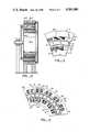
- FIG. 2is an elevational, side view, in section of the assembled motor of the invention
- FIG. 3is an enlarged, elevational view, taken generally along the lines 3--3 in FIG. 2;
- FIG. 4is a diagrammatic illustration of the phase winding arrangement of the motor.
- FIG. 5is a block diagram of the motor's electronic drive circuitry.
- the motor of the present inventionis comprised of an inner stator assembly 10, a rotor 12, and an outer stator assembly 14.
- the rotor 12is co-axially positioned between the inner stator assembly 10 and the outer stator assembly 14 about a hypothetical axis of rotation 16.
- Each of the structures 10, 12, and 14is made up of separate laminations of soft iron.
- each of the inner and outer statorsis provided with a plurality of pole pieces 18 and 20, respectively, which are arranged at regular, angular intervals about the axis of revolution 16.
- the inner stator pole pieces 18are aligned with the corresponding outer stator pole pieces 20.
- Each of the pole pieces 18is provided with pole piece teeth 22 and each of the pole pieces 20 is likewise provided with pole piece teeth 28.
- the rotor 12is provided with two sets of teeth 24 and 26 which are opposed to the pole piece teeth 22 and 28, respectively. All of the teeth 22-28 are intersected by a hypothetical plane which is perpendicular to the axis of revolution 16.
- a separate electrical coil 30surrounds each pole piece 18 of the inner stator and a separate electrical coil 32 surrounds each pole piece 20 of the outer stator.
- the coils 30 and 32 of the opposed pole pieces 18 and 20are electrically connected in series so that when an electric current is passed through the coils, a magnetic field will be generated across the portion of the rotor 12 between the poles 18 and 20.
- the stator pole 18will have a magnetic polarity which is opposite to that of the opposed stator pole 20.
- a magnetic flux path 34is generated.
- This path 34travels from the inner stator pole 18', across that portion of the rotor 12 between the stator poles 18' and 20' and through the stator pole 20'.
- the path 34continues on through the outer stator 14 along its circumference, past two unenergized windings, and back through the other stator pole 20", through the rotor 12, and through the inner stator pole 18", to return along the inner stator to the original inner stator pole 18', thereby completing the closed loop.
- the important conceptis that no flux travels through the rotor in a circumferential direction to take a short cut to the next stator pole. Instead, all of the magnetic flux travels through the rotor 12 in a radially outward or radially inward direction. If one of the aligned stator poles 18' or 20' were not there or were not energized, the magnetic flux would have to return through the rotor, in a circumferential direction. The rotor 12 in such case would have to be thicker and would have less than half the torque, because only half of its teeth would be magnetically engaged and because of the improved flux paths.
- the rotative force for the rotoris derived from the fact that the teeth on each succeeding stator pole piece set are slightly out of alignment with the opposed teeth of the rotor due to the spacing between the adjacent stator pole pieces.
- the teeth on the rotor which reside between the energized pole pieceswill be forced to fall into alignment with the teeth on the energized stator pole pieces.
- the teeth on the portion of the rotor which is positioned between the next adjacent, unenergized pole pieceswill not be in alignment with the stator teeth because the pole pieces are spaced apart by a distance which is not an integral multiple of the teeth spacing.
- the difference between the number of outer stator teeth and the number of rotor teeth which face the outer stator teethis equal to the number of outer stator poles divided by the number of phases.
- the rotorAs power is supplied to the coils of each succeeding phase, the rotor will be caused to move to place the rotor teeth into alignment with the stator teeth in each succeeding phase and, thus, the rotor will rotate in the same direction in which power is successively supplied to each of the phases of the motor.
- the magnetic step angle of the motormust be an even multiple of 360 for a radial turn style or robot arm applications.
- Other applicationsmay require round numbers divisible by 5, such as for turning lead screws because of the common five turns per inch screw standard.
- the rotorhas 150 teeth, while each stator has 144 teeth. 150 rotor teeth times 3 phases makes this a 450 magnetic step per revolution motor, which is an even multiplicand of 3600.
- the motor according to the inventionis designed to be microstepped. This is done by electronically dividing the magnetic steps into smaller substeps.
- FIG. 5a more or less conventional circuit for driving the motor is schematically illustrated.
- Each combined winding 30a and 32a, 30b and 32b, 30c and 32c, of given, aligned sets of inner and outer stator poles corresponding to the first, second and third phases, respectively,is connected to the output of a separate one of three digital to analog converters 38a, 38b, 38c, respectively, through power amplifiers.
- the separate inputs to each of the digital to analog convertersare supplied by separate programed read-only memories (PROMs) 40a, 40b, 40c, respectively.
- PROMsprogramed read-only memories
- the inputs to each of the PROMsare separately addressed in sequence by a counter 42 under the control of a timing logic circuit 44.
- the counteris supplied with a clock input 48 and a direction input 46, which selectively causes the counter to count up or down.
- Each of the PROMs 40a, 40b, and 40cstores a special waveform signal, in digital form, particularly designed for energizing the coils for smooth rotor rotation and constant torque.
- the current in the coils of one phaseis reduced in discrete steps, while the current in the coils of the next adjacent phase is increased in discrete steps. This is done simply by the manner in which the PROMs corresponding to the coils in each of the succeeding phases are addressed, i.e. the pattern of the interconnections between the PROMs 40a, 40b and 40c and the outputs of the counters 42.
- a magnetic flux pathas indicated at 35 in FIG. 4, is generated in which the flux encircles the adjacent poles.
- the division of the flux between paths 34 and 35is relative to the amount of electric current flowing through the respective sets of coils.
Landscapes
- Engineering & Computer Science (AREA)
- Power Engineering (AREA)
- Control Of Stepping Motors (AREA)
- Iron Core Of Rotating Electric Machines (AREA)
- Manipulator (AREA)
- Magnetic Resonance Imaging Apparatus (AREA)
Abstract
Description
______________________________________ Inner/Outer Inner/Outer Teeth/ Stator Teeth Rotor Magnetic Step/ Poles Pole Total Teeth Revolution ______________________________________ 18 5 90 96 288 18 7 126 120 360 18 8 144 150 450 12 5 60 64 192 12 7 84 80 240 12 8 96 100 300 6 5 30 32 96 6 7 42 40 120 6 8 48 50 150 ______________________________________
Claims (9)
______________________________________ First Total First Rotor Stator Poles Teeth/Pole Stator Pole Teeth Teeth ______________________________________ 18 5 90 96 18 7 126 120 18 8 144 150 12 5 60 64 12 7 84 80 12 8 96 100 6 5 30 32 6 7 42 40 6 8 48 50 ______________________________________
______________________________________ Number of Total Stator Poles Teeth/Pole Stator Teeth Rotor Teeth ______________________________________ 18 5 90 96 18 7 126 120 18 8 144 150 12 5 60 64 12 7 84 80 12 8 96 100 6 5 30 32 6 7 42 40 ______________________________________
Priority Applications (7)
| Application Number | Priority Date | Filing Date | Title |
|---|---|---|---|
| US06/385,034US4501980A (en) | 1982-06-04 | 1982-06-04 | High torque robot motor |
| DE8383105512TDE3374504D1 (en) | 1982-06-04 | 1983-06-03 | High torque robot motor |
| JP58100108AJPH0681480B2 (en) | 1982-06-04 | 1983-06-03 | Motor for high torque robot |
| EP83105512AEP0096390B1 (en) | 1982-06-04 | 1983-06-03 | High torque robot motor |
| CA000429733ACA1196368A (en) | 1982-06-04 | 1983-06-06 | High torque robot motor |
| US06/556,083US4551708A (en) | 1982-06-04 | 1983-11-29 | Reactance-commutated high resolution servo motor system |
| JP4242973AJPH06121518A (en) | 1982-06-04 | 1992-09-11 | Motor for high-torque robot |
Applications Claiming Priority (1)
| Application Number | Priority Date | Filing Date | Title |
|---|---|---|---|
| US06/385,034US4501980A (en) | 1982-06-04 | 1982-06-04 | High torque robot motor |
Related Child Applications (1)
| Application Number | Title | Priority Date | Filing Date |
|---|---|---|---|
| US06/556,083Continuation-In-PartUS4551708A (en) | 1982-06-04 | 1983-11-29 | Reactance-commutated high resolution servo motor system |
Publications (1)
| Publication Number | Publication Date |
|---|---|
| US4501980Atrue US4501980A (en) | 1985-02-26 |
Family
ID=23519763
Family Applications (1)
| Application Number | Title | Priority Date | Filing Date |
|---|---|---|---|
| US06/385,034Expired - LifetimeUS4501980A (en) | 1982-06-04 | 1982-06-04 | High torque robot motor |
Country Status (5)
| Country | Link |
|---|---|
| US (1) | US4501980A (en) |
| EP (1) | EP0096390B1 (en) |
| JP (2) | JPH0681480B2 (en) |
| CA (1) | CA1196368A (en) |
| DE (1) | DE3374504D1 (en) |
Cited By (61)
| Publication number | Priority date | Publication date | Assignee | Title |
|---|---|---|---|---|
| US4710606A (en)* | 1986-05-28 | 1987-12-01 | Westinghouse Electric Corp. | Two-axis optic wrist for laser applications |
| US4714853A (en)* | 1986-09-04 | 1987-12-22 | Tri-Tech, Inc. | Low profile electric motor |
| US4754183A (en)* | 1985-12-10 | 1988-06-28 | Saia Ag | Stepping or reversible motor |
| US4758756A (en)* | 1984-04-13 | 1988-07-19 | Alsthom-Atlantique | Vernier-type electrodynamic machine |
| US4794286A (en)* | 1986-04-03 | 1988-12-27 | Adept Technology, Inc. | Variable reluctance stepper motor |
| EP0306192A3 (en)* | 1987-08-28 | 1989-06-07 | Eli Lilly And Company | Permeation enhancement compositions |
| US4890024A (en)* | 1987-04-24 | 1989-12-26 | Hitachi, Ltd. | Low-speed high-torque motor |
| US4900965A (en)* | 1988-09-28 | 1990-02-13 | Fisher Technology, Inc. | Lightweight high power electromotive device |
| US4943760A (en)* | 1984-10-19 | 1990-07-24 | Kollmorgen Corporation | Control systems for variable reluctance electrical machines |
| US5004944A (en)* | 1985-12-23 | 1991-04-02 | Unique Mobility, Inc. | Lightweight high power electromagnetic transducer |
| US5072651A (en)* | 1990-03-19 | 1991-12-17 | Nippon Seiko Kabushiki Kaisha | Direct drive type rotation dividing table |
| US5212419A (en)* | 1992-01-10 | 1993-05-18 | Fisher Electric Motor Technology, Inc. | Lightweight high power electromotive device |
| US5315190A (en)* | 1992-12-22 | 1994-05-24 | Stirling Technology Company | Linear electrodynamic machine and method of using same |
| US5319844A (en)* | 1985-12-23 | 1994-06-14 | Unique Mobility, Inc. | Method of making an electromagnetic transducer |
| US5481147A (en)* | 1992-02-20 | 1996-01-02 | Dana Corporation | Synchronous inductor electric motor |
| US5495131A (en)* | 1993-05-28 | 1996-02-27 | Satcon Technology Corp. | Parallel air gap serial flux A.C. electrical machine |
| WO1998023024A1 (en)* | 1996-11-20 | 1998-05-28 | Iancu Lungu | Electronically switched two phases reluctance machine |
| US5818144A (en)* | 1994-07-12 | 1998-10-06 | Samsung Electro-Mechanics Co., Ltd. | Linear type induction motor having inner and outer stators |
| US5834865A (en)* | 1996-06-03 | 1998-11-10 | Tamagawa Seiki Kabushiki Kaisha | Hybrid stepping motor |
| US5856714A (en)* | 1996-07-05 | 1999-01-05 | Tamagawa Seiki Kaubushiki Kaisha | Hybrid type stepping motor |
| NL1009735C2 (en)* | 1998-07-24 | 2000-01-25 | Iku Holding Montfoort Bv | Stepper motor combination and mirror for a vehicle, provided with such a stepper motor combination. |
| WO2000038297A1 (en)* | 1998-12-22 | 2000-06-29 | Rush Holdings, Inc. | Machine with cup-shaped armature and air gap |
| US6304010B1 (en)* | 1995-12-21 | 2001-10-16 | Tamagawa Seiki Kabushiki Kaisha | Hybrid-type stepping motor |
| WO2002093720A1 (en)* | 2001-05-16 | 2002-11-21 | Trinity Motors Inc. | Universal motor/generator/alternator apparatus |
| US20030117026A1 (en)* | 2001-12-21 | 2003-06-26 | Canon Kabushiki Kaisha | Moving-magnet linear motor, aligner and apparatus provided therewith, and method for manufacturing devices using the same |
| US20040150289A1 (en)* | 2002-05-14 | 2004-08-05 | James Gordon G | Universal motor/generator/alternator apparatus |
| US6876122B2 (en) | 2002-09-16 | 2005-04-05 | Lockheed Martin Corporation | Circular rail linear induction motor |
| US20070013237A1 (en)* | 2005-07-15 | 2007-01-18 | Lin Engineering, Inc. | Accurate microstepping motor |
| US20070125480A1 (en)* | 2005-12-01 | 2007-06-07 | Henthorne David A | Synchronous drive and method for tire cord application |
| US20070138896A1 (en)* | 2003-04-09 | 2007-06-21 | Zhengfeng Zhu | Outer magnetic circuit bias magnetic bias reluctance machine with permanent magnets |
| US20070222304A1 (en)* | 2004-09-22 | 2007-09-27 | Siemens Aktiengesellschaft | Electric machine |
| US20080246359A1 (en)* | 2007-04-05 | 2008-10-09 | Samsung Electronics Co., Ltd. | Motor and drum washing machine having the same |
| US20080309188A1 (en)* | 2007-05-09 | 2008-12-18 | David Gregory Calley | Electrical output generating devices and driven electrical devices with reduced flux leakage using permanent magnet components, and methods of making and using the same |
| US20090206696A1 (en)* | 2007-05-09 | 2009-08-20 | David Gregory Calley | Electrical output generating and driven devices using disk and non-disk shaped rotors, and methods of making and using the same |
| CN101604890A (en)* | 2008-06-12 | 2009-12-16 | 通用电气公司 | High torque density electrical machine |
| US20100109452A1 (en)* | 2008-11-03 | 2010-05-06 | Motor Excellence Llc | Transverse and/or commutated flux system rotor concepts |
| US20100171384A1 (en)* | 2009-01-07 | 2010-07-08 | Shimon Elmaleh | Electro-magnetic motor generator system |
| WO2011015004A1 (en)* | 2009-08-03 | 2011-02-10 | 东莞洲亮通讯科技有限公司 | Electromotor with coaxial inner and outer coils |
| US20110169366A1 (en)* | 2010-03-15 | 2011-07-14 | Motor Excellence Llc | Transverse and/or commutated systems having phase offset |
| US20110169381A1 (en)* | 2010-03-15 | 2011-07-14 | Motor Excellence Llc | Transverse and/or commutated flux systems for electric bicycles |
| US20110169365A1 (en)* | 2010-03-15 | 2011-07-14 | Motor Excellence Llc | Transverse and/or commutated flux systems configured to provide reduced flux leakage, hysteresis loss reduction, and phase matching |
| US20120032545A1 (en)* | 2010-08-04 | 2012-02-09 | Liang-Yi Hsu | Magnetic-controlled actuator with auto-locking function for joints of manipulation arm |
| DE202011100455U1 (en)* | 2011-05-09 | 2012-05-10 | Peter Fendt | Robot with multiple articulated arms |
| US8405275B2 (en) | 2010-11-17 | 2013-03-26 | Electric Torque Machines, Inc. | Transverse and/or commutated flux systems having segmented stator laminations |
| US8836196B2 (en) | 2010-11-17 | 2014-09-16 | Electric Torque Machines, Inc. | Transverse and/or commutated flux systems having segmented stator laminations |
| US8952590B2 (en) | 2010-11-17 | 2015-02-10 | Electric Torque Machines Inc | Transverse and/or commutated flux systems having laminated and powdered metal portions |
| US20150288235A1 (en)* | 2012-12-28 | 2015-10-08 | Ihi Corporation | Double stator switched reluctance rotating machine |
| DE102014219940A1 (en)* | 2014-10-01 | 2016-04-07 | Robert Bosch Gmbh | Induction machine |
| US9647520B2 (en) | 2013-01-10 | 2017-05-09 | Ihi Corporation | Double stator switched reluctance rotating machine |
| US9742225B2 (en) | 2015-08-11 | 2017-08-22 | Genesis Robotics Llp | Electric machine |
| WO2018046585A1 (en)* | 2016-09-09 | 2018-03-15 | Brose Schliesssysteme Gmbh & Co. Kommanditgesellschaft | Motor vehicle lock |
| DE102017122067A1 (en)* | 2017-09-22 | 2019-03-28 | Roschiwal + Partner Ingenieur Gmbh Augsburg | milling robot |
| CN110429778A (en)* | 2019-08-31 | 2019-11-08 | 郑州大学 | A kind of electronic automobile-used U-shaped double-stator structure switched reluctance machines |
| CN111799926A (en)* | 2020-07-06 | 2020-10-20 | 东莞市吉铼升电机股份有限公司 | A kind of micro motor and its rotor winding method |
| EP3691086A4 (en)* | 2017-09-28 | 2021-06-16 | Kang, Dohyun | ROTATING ELECTRICAL DEVICE |
| US11043885B2 (en) | 2016-07-15 | 2021-06-22 | Genesis Robotics And Motion Technologies Canada, Ulc | Rotary actuator |
| US11139707B2 (en) | 2015-08-11 | 2021-10-05 | Genesis Robotics And Motion Technologies Canada, Ulc | Axial gap electric machine with permanent magnets arranged between posts |
| US11211837B2 (en) | 2019-06-25 | 2021-12-28 | General Dynamics Land Systems—Canada | Actuator with individually computerized and networked electromagnetic poles |
| US20220069685A1 (en)* | 2020-08-28 | 2022-03-03 | Quantentech Limited | High Efficiency High Density Motor and Generator with Multiple Airgaps |
| US20230313564A1 (en)* | 2020-08-26 | 2023-10-05 | Assa Abloy Ab | Arrangement for lock device, lock device comprising arrangement, and method |
| US11967871B2 (en) | 2017-09-15 | 2024-04-23 | University Of Utah Research Foundation | Cogging-torque actuator |
Families Citing this family (15)
| Publication number | Priority date | Publication date | Assignee | Title |
|---|---|---|---|---|
| DE3579291D1 (en)* | 1984-10-19 | 1990-09-27 | Kollmorgen Corp | SERVOMOTOR CONTROL SYSTEM. |
| JPH0742226Y2 (en)* | 1985-02-22 | 1995-09-27 | 三菱電機株式会社 | Permanent magnet field synchronous machine |
| FR2606225B1 (en)* | 1986-10-30 | 1991-04-26 | France Etat Armement | ELECTROMAGNETIC ACTUATOR WITH TWO GAPS |
| JP2512918B2 (en)* | 1986-12-05 | 1996-07-03 | 日本電装株式会社 | Stepping motor and engine intake air amount control device |
| DE3821660C1 (en)* | 1988-06-27 | 1989-08-10 | Robert Bosch Gmbh, 7000 Stuttgart, De | Reluctance machine |
| JPH0214287U (en)* | 1988-07-08 | 1990-01-29 | ||
| WO1990007219A1 (en)* | 1988-12-19 | 1990-06-28 | Boral Johns Perry Industries Pty. Ltd. | Motor |
| KR20030045980A (en)* | 2001-12-03 | 2003-06-12 | (주)티엠디바이스 | Structure of induction ac servo motor |
| CN102371589B (en)* | 2010-08-13 | 2013-12-18 | 台达电子工业股份有限公司 | Magnetic controlled robotic arm joint brake with power-off self-locking function |
| KR101216857B1 (en)* | 2011-02-25 | 2013-01-09 | 조윤현 | Switched reluctance rotating machine |
| RU2752723C2 (en) | 2017-04-21 | 2021-07-30 | Зенимакс Медиа Инк. | Systems and methods for rendering and issuing prompts to encoder based on estimation of pre-coded load |
| JP6984001B2 (en) | 2017-04-21 | 2021-12-17 | ゼニマックス メディア インク.Zenimax Media Inc. | Systems and methods for motion compensation of player inputs for motion vector prediction |
| GB2576286B (en) | 2017-04-21 | 2022-09-07 | Zenimax Media Inc | Systems and methods for deferred post-processes in video encoding |
| TWI691199B (en) | 2017-04-21 | 2020-04-11 | 美商時美媒體公司 | System and method for generating motion vector of game |
| GB2576662B (en) | 2017-04-21 | 2020-10-28 | Zenimax Media Inc | Systems and methods for encoder-guided adaptive-quality rendering |
Citations (12)
| Publication number | Priority date | Publication date | Assignee | Title |
|---|---|---|---|---|
| US2627040A (en)* | 1950-08-01 | 1953-01-27 | Hansen Siegfried | Stepping motor |
| US3162796A (en)* | 1960-08-04 | 1964-12-22 | Siemens Ag | Electromagnetic linear motor |
| US3292065A (en)* | 1964-01-27 | 1966-12-13 | Superior Electric Co | Linear electric motor and control system |
| FR1469257A (en)* | 1965-01-13 | 1967-02-10 | Philips Nv | Stepper motor that can operate as an asynchronous motor |
| US3629626A (en)* | 1969-09-22 | 1971-12-21 | Frank R Abbott | Low-inertia, high-torque motors |
| US3867676A (en)* | 1973-09-20 | 1975-02-18 | Ibm | Variable reluctance linear stepper motor |
| JPS5029211A (en)* | 1973-07-12 | 1975-03-25 | ||
| US4029977A (en)* | 1975-11-26 | 1977-06-14 | International Business Machines Corporation | Rotary stepper motor and method of operation |
| US4035680A (en)* | 1975-06-17 | 1977-07-12 | Pont-A-Mousson S.A. | Variable reluctance motor |
| US4070592A (en)* | 1976-10-08 | 1978-01-24 | The Superior Electric Company | Three step sequence motor |
| US4286180A (en)* | 1978-07-20 | 1981-08-25 | Kollmorgen Technologies Corporation | Variable reluctance stepper motor |
| US4288709A (en)* | 1977-06-24 | 1981-09-08 | Exxon Research & Engineering Co. | High performance stepper motor |
Family Cites Families (6)
| Publication number | Priority date | Publication date | Assignee | Title |
|---|---|---|---|---|
| US3666305A (en)* | 1970-12-04 | 1972-05-30 | Ford Motor Co | Door latch assembly |
| JPS4831513U (en)* | 1971-08-24 | 1973-04-17 | ||
| JPS5029211U (en)* | 1973-07-10 | 1975-04-03 | ||
| GB1556404A (en)* | 1976-06-17 | 1979-11-21 | Berger Elektr Messgeraete Gmbh | Electrical stepping motor apparatus |
| JPS54106814A (en)* | 1978-02-09 | 1979-08-22 | Seiko Epson Corp | One-two phase excitation driving circuit for three-phase pulse motor |
| DE2822830A1 (en)* | 1978-05-24 | 1979-11-29 | Intermadox Ag | Permanent magnet rotor stepper motor - is constructed with magnets forming rotor teeth and coating with stator teeth |
- 1982
- 1982-06-04USUS06/385,034patent/US4501980A/ennot_activeExpired - Lifetime
- 1983
- 1983-06-03JPJP58100108Apatent/JPH0681480B2/ennot_activeExpired - Lifetime
- 1983-06-03DEDE8383105512Tpatent/DE3374504D1/ennot_activeExpired
- 1983-06-03EPEP83105512Apatent/EP0096390B1/ennot_activeExpired
- 1983-06-06CACA000429733Apatent/CA1196368A/ennot_activeExpired
- 1992
- 1992-09-11JPJP4242973Apatent/JPH06121518A/enactivePending
Patent Citations (12)
| Publication number | Priority date | Publication date | Assignee | Title |
|---|---|---|---|---|
| US2627040A (en)* | 1950-08-01 | 1953-01-27 | Hansen Siegfried | Stepping motor |
| US3162796A (en)* | 1960-08-04 | 1964-12-22 | Siemens Ag | Electromagnetic linear motor |
| US3292065A (en)* | 1964-01-27 | 1966-12-13 | Superior Electric Co | Linear electric motor and control system |
| FR1469257A (en)* | 1965-01-13 | 1967-02-10 | Philips Nv | Stepper motor that can operate as an asynchronous motor |
| US3629626A (en)* | 1969-09-22 | 1971-12-21 | Frank R Abbott | Low-inertia, high-torque motors |
| JPS5029211A (en)* | 1973-07-12 | 1975-03-25 | ||
| US3867676A (en)* | 1973-09-20 | 1975-02-18 | Ibm | Variable reluctance linear stepper motor |
| US4035680A (en)* | 1975-06-17 | 1977-07-12 | Pont-A-Mousson S.A. | Variable reluctance motor |
| US4029977A (en)* | 1975-11-26 | 1977-06-14 | International Business Machines Corporation | Rotary stepper motor and method of operation |
| US4070592A (en)* | 1976-10-08 | 1978-01-24 | The Superior Electric Company | Three step sequence motor |
| US4288709A (en)* | 1977-06-24 | 1981-09-08 | Exxon Research & Engineering Co. | High performance stepper motor |
| US4286180A (en)* | 1978-07-20 | 1981-08-25 | Kollmorgen Technologies Corporation | Variable reluctance stepper motor |
Non-Patent Citations (2)
| Title |
|---|
| IBM Tech Disclosure Bulleton, "Linear Incremental Motor", Thompson, vol. 6, No. 9. |
| IBM Tech Disclosure Bulleton, Linear Incremental Motor , Thompson, vol. 6, No. 9.* |
Cited By (125)
| Publication number | Priority date | Publication date | Assignee | Title |
|---|---|---|---|---|
| US4758756A (en)* | 1984-04-13 | 1988-07-19 | Alsthom-Atlantique | Vernier-type electrodynamic machine |
| US4943760A (en)* | 1984-10-19 | 1990-07-24 | Kollmorgen Corporation | Control systems for variable reluctance electrical machines |
| US4754183A (en)* | 1985-12-10 | 1988-06-28 | Saia Ag | Stepping or reversible motor |
| US5004944A (en)* | 1985-12-23 | 1991-04-02 | Unique Mobility, Inc. | Lightweight high power electromagnetic transducer |
| US5319844A (en)* | 1985-12-23 | 1994-06-14 | Unique Mobility, Inc. | Method of making an electromagnetic transducer |
| US4794286A (en)* | 1986-04-03 | 1988-12-27 | Adept Technology, Inc. | Variable reluctance stepper motor |
| US4710606A (en)* | 1986-05-28 | 1987-12-01 | Westinghouse Electric Corp. | Two-axis optic wrist for laser applications |
| US4714853A (en)* | 1986-09-04 | 1987-12-22 | Tri-Tech, Inc. | Low profile electric motor |
| US4890024A (en)* | 1987-04-24 | 1989-12-26 | Hitachi, Ltd. | Low-speed high-torque motor |
| EP0306192A3 (en)* | 1987-08-28 | 1989-06-07 | Eli Lilly And Company | Permeation enhancement compositions |
| US4900965A (en)* | 1988-09-28 | 1990-02-13 | Fisher Technology, Inc. | Lightweight high power electromotive device |
| US5072651A (en)* | 1990-03-19 | 1991-12-17 | Nippon Seiko Kabushiki Kaisha | Direct drive type rotation dividing table |
| US5212419A (en)* | 1992-01-10 | 1993-05-18 | Fisher Electric Motor Technology, Inc. | Lightweight high power electromotive device |
| US5481147A (en)* | 1992-02-20 | 1996-01-02 | Dana Corporation | Synchronous inductor electric motor |
| US5485046A (en)* | 1992-02-20 | 1996-01-16 | Dana Corporation | Variable reluctance electric motor |
| WO1994015392A1 (en)* | 1992-12-22 | 1994-07-07 | Stirling Technology Company | Linear electrodynamic machine and method of using same |
| US5654596A (en)* | 1992-12-22 | 1997-08-05 | Stirling Technology Company | Linear electrodynamic machine and method of making and using same |
| US5315190A (en)* | 1992-12-22 | 1994-05-24 | Stirling Technology Company | Linear electrodynamic machine and method of using same |
| US5495131A (en)* | 1993-05-28 | 1996-02-27 | Satcon Technology Corp. | Parallel air gap serial flux A.C. electrical machine |
| US5818144A (en)* | 1994-07-12 | 1998-10-06 | Samsung Electro-Mechanics Co., Ltd. | Linear type induction motor having inner and outer stators |
| US6304010B1 (en)* | 1995-12-21 | 2001-10-16 | Tamagawa Seiki Kabushiki Kaisha | Hybrid-type stepping motor |
| US5834865A (en)* | 1996-06-03 | 1998-11-10 | Tamagawa Seiki Kabushiki Kaisha | Hybrid stepping motor |
| US5856714A (en)* | 1996-07-05 | 1999-01-05 | Tamagawa Seiki Kaubushiki Kaisha | Hybrid type stepping motor |
| WO1998023024A1 (en)* | 1996-11-20 | 1998-05-28 | Iancu Lungu | Electronically switched two phases reluctance machine |
| US6359360B1 (en) | 1996-11-20 | 2002-03-19 | Iancu Lungu | Electronically switched two phases reluctance machine |
| WO2000005803A1 (en)* | 1998-07-24 | 2000-02-03 | Iku Holding Montfoort B.V. | Stepping motor combination and mirror for a vehicle, provided with such a stepping motor combination |
| NL1009735C2 (en)* | 1998-07-24 | 2000-01-25 | Iku Holding Montfoort Bv | Stepper motor combination and mirror for a vehicle, provided with such a stepper motor combination. |
| WO2000038297A1 (en)* | 1998-12-22 | 2000-06-29 | Rush Holdings, Inc. | Machine with cup-shaped armature and air gap |
| US6617748B2 (en) | 1998-12-22 | 2003-09-09 | Rush Holdings Inc | Machine with cup-shaped armature and air gap |
| WO2002093720A1 (en)* | 2001-05-16 | 2002-11-21 | Trinity Motors Inc. | Universal motor/generator/alternator apparatus |
| US20030117026A1 (en)* | 2001-12-21 | 2003-06-26 | Canon Kabushiki Kaisha | Moving-magnet linear motor, aligner and apparatus provided therewith, and method for manufacturing devices using the same |
| US6791214B2 (en)* | 2001-12-21 | 2004-09-14 | Canon Kabushiki Kaisha | Moving-magnet linear motor, aligner and apparatus provided therewith, and method for manufacturing devices using the same |
| US20040150289A1 (en)* | 2002-05-14 | 2004-08-05 | James Gordon G | Universal motor/generator/alternator apparatus |
| US6876122B2 (en) | 2002-09-16 | 2005-04-05 | Lockheed Martin Corporation | Circular rail linear induction motor |
| US20070138896A1 (en)* | 2003-04-09 | 2007-06-21 | Zhengfeng Zhu | Outer magnetic circuit bias magnetic bias reluctance machine with permanent magnets |
| US20070222304A1 (en)* | 2004-09-22 | 2007-09-27 | Siemens Aktiengesellschaft | Electric machine |
| US7800256B2 (en)* | 2004-09-22 | 2010-09-21 | Siemens Aktiengesellschaft | Electric machine |
| US7518270B2 (en) | 2005-07-15 | 2009-04-14 | Lin Engineering, Inc. | Accurate microstepping motor |
| US20070013237A1 (en)* | 2005-07-15 | 2007-01-18 | Lin Engineering, Inc. | Accurate microstepping motor |
| US20070125480A1 (en)* | 2005-12-01 | 2007-06-07 | Henthorne David A | Synchronous drive and method for tire cord application |
| US20090090456A1 (en)* | 2005-12-01 | 2009-04-09 | The Goodyear Tire & Rubber Company | Synchronous drive and method for tire cord application |
| US7830064B2 (en)* | 2007-04-05 | 2010-11-09 | Samsung Electronics Co., Ltd | Motor and drum washing machine having the same |
| US20080246359A1 (en)* | 2007-04-05 | 2008-10-09 | Samsung Electronics Co., Ltd. | Motor and drum washing machine having the same |
| US20110221298A1 (en)* | 2007-05-09 | 2011-09-15 | Motor Excellence, Llc | Electrical devices having tape wound core laminate rotor or stator elements |
| US20090208771A1 (en)* | 2007-05-09 | 2009-08-20 | Thomas Janecek | Powdered metal manufacturing method and devices |
| US20090206693A1 (en)* | 2007-05-09 | 2009-08-20 | David Gregory Calley | Electrical output generating devices and driven electrical devices having tape wound core laminate rotor or stator elements, and methods of making and use thereof |
| US7973446B2 (en) | 2007-05-09 | 2011-07-05 | Motor Excellence, Llc | Electrical devices having tape wound core laminate rotor or stator elements |
| US20090206696A1 (en)* | 2007-05-09 | 2009-08-20 | David Gregory Calley | Electrical output generating and driven devices using disk and non-disk shaped rotors, and methods of making and using the same |
| US7876019B2 (en) | 2007-05-09 | 2011-01-25 | Motor Excellence, Llc | Electrical devices with reduced flux leakage using permanent magnet components |
| US7868511B2 (en) | 2007-05-09 | 2011-01-11 | Motor Excellence, Llc | Electrical devices using disk and non-disk shaped rotors |
| US7989084B2 (en) | 2007-05-09 | 2011-08-02 | Motor Excellence, Llc | Powdered metal manufacturing method and devices |
| US7863797B2 (en) | 2007-05-09 | 2011-01-04 | Motor Excellence, Llc | Electrical devices using electromagnetic rotors |
| US20080309188A1 (en)* | 2007-05-09 | 2008-12-18 | David Gregory Calley | Electrical output generating devices and driven electrical devices with reduced flux leakage using permanent magnet components, and methods of making and using the same |
| US20100295410A1 (en)* | 2007-05-09 | 2010-11-25 | Motor Excellence Llc. | Electrical devices using electromagnetic rotors |
| US20090309442A1 (en)* | 2008-06-12 | 2009-12-17 | General Electric Company | High torque density electrical machine |
| US8847464B2 (en)* | 2008-06-12 | 2014-09-30 | General Electric Company | Electrical machine with improved stator flux pattern across a rotor that permits higher torque density |
| US20140361653A1 (en)* | 2008-06-12 | 2014-12-11 | General Electric Company | High torque density electrical machine |
| CN101604890B (en)* | 2008-06-12 | 2015-06-17 | 通用电气公司 | Electrical machine with improved stators magnetic pattern by allowing rotors to deliver high torque density |
| US9537362B2 (en)* | 2008-06-12 | 2017-01-03 | General Electric Company | Electrical machine with improved stator flux pattern across a rotor for providing high torque density |
| CN101604890A (en)* | 2008-06-12 | 2009-12-16 | 通用电气公司 | High torque density electrical machine |
| US7923886B2 (en)* | 2008-11-03 | 2011-04-12 | Motor Excellence, Llc | Transverse and/or commutated flux system rotor concepts |
| US8030819B2 (en) | 2008-11-03 | 2011-10-04 | Motor Excellence, Llc | Transverse and/or commutated flux system rotor concepts |
| US20110062723A1 (en)* | 2008-11-03 | 2011-03-17 | Motor Excellence, Llc | Polyphase transverse and/or commutated flux systems |
| US20110050010A1 (en)* | 2008-11-03 | 2011-03-03 | Motor Excellence Llc | Transverse and/or commutated flux system stator concepts |
| US20110148225A1 (en)* | 2008-11-03 | 2011-06-23 | Motor Excellence Llc | Transverse and/or commutated flux system rotor concepts |
| US20100109452A1 (en)* | 2008-11-03 | 2010-05-06 | Motor Excellence Llc | Transverse and/or commutated flux system rotor concepts |
| US8242658B2 (en)* | 2008-11-03 | 2012-08-14 | Electric Torque Machines Inc. | Transverse and/or commutated flux system rotor concepts |
| US20120001501A1 (en)* | 2008-11-03 | 2012-01-05 | Motor Excellence, Llc | Transverse and/or commutated flux system rotor concepts |
| US20100109462A1 (en)* | 2008-11-03 | 2010-05-06 | Motor Excellence Llc | Transverse and/or commutated flux system stator concepts |
| US7868508B2 (en) | 2008-11-03 | 2011-01-11 | Motor Excellence, Llc | Polyphase transverse and/or commutated flux systems |
| US7994678B2 (en) | 2008-11-03 | 2011-08-09 | Motor Excellence, Llc | Polyphase transverse and/or commutated flux systems |
| US8008821B2 (en) | 2008-11-03 | 2011-08-30 | Motor Excellence, Llc | Transverse and/or commutated flux system stator concepts |
| US7851965B2 (en) | 2008-11-03 | 2010-12-14 | Motor Excellence, Llc | Transverse and/or commutated flux system stator concepts |
| US8193679B2 (en) | 2008-11-03 | 2012-06-05 | Motor Excellence Llc | Polyphase transverse and/or commutated flux systems |
| US20100109453A1 (en)* | 2008-11-03 | 2010-05-06 | Motor Excellence Llc | Polyphase transverse and/or commutated flux systems |
| CN102257708A (en)* | 2008-11-03 | 2011-11-23 | 卓越发动机有限责任公司 | Transverse and/or commutated flux system rotor concepts |
| US7902708B2 (en)* | 2009-01-07 | 2011-03-08 | Shimon Elmaleh | Electro-magnetic motor generator system |
| US20100171384A1 (en)* | 2009-01-07 | 2010-07-08 | Shimon Elmaleh | Electro-magnetic motor generator system |
| WO2011015004A1 (en)* | 2009-08-03 | 2011-02-10 | 东莞洲亮通讯科技有限公司 | Electromotor with coaxial inner and outer coils |
| US20110169365A1 (en)* | 2010-03-15 | 2011-07-14 | Motor Excellence Llc | Transverse and/or commutated flux systems configured to provide reduced flux leakage, hysteresis loss reduction, and phase matching |
| US8222786B2 (en) | 2010-03-15 | 2012-07-17 | Motor Excellence Llc | Transverse and/or commutated flux systems having phase offset |
| US8395291B2 (en) | 2010-03-15 | 2013-03-12 | Electric Torque Machines, Inc. | Transverse and/or commutated flux systems for electric bicycles |
| US8053944B2 (en) | 2010-03-15 | 2011-11-08 | Motor Excellence, Llc | Transverse and/or commutated flux systems configured to provide reduced flux leakage, hysteresis loss reduction, and phase matching |
| US8415848B2 (en) | 2010-03-15 | 2013-04-09 | Electric Torque Machines, Inc. | Transverse and/or commutated flux systems configured to provide reduced flux leakage, hysteresis loss reduction, and phase matching |
| US8760023B2 (en)* | 2010-03-15 | 2014-06-24 | Electric Torque Machines, Inc. | Transverse and/or commutated flux systems having phase offset |
| US20110169381A1 (en)* | 2010-03-15 | 2011-07-14 | Motor Excellence Llc | Transverse and/or commutated flux systems for electric bicycles |
| US20110169366A1 (en)* | 2010-03-15 | 2011-07-14 | Motor Excellence Llc | Transverse and/or commutated systems having phase offset |
| US20120032545A1 (en)* | 2010-08-04 | 2012-02-09 | Liang-Yi Hsu | Magnetic-controlled actuator with auto-locking function for joints of manipulation arm |
| TWI413347B (en)* | 2010-08-04 | 2013-10-21 | Delta Electronics Inc | Magnetic-controlled actuator with auto-locking function for joints of manipulate arm |
| US8598757B2 (en)* | 2010-08-04 | 2013-12-03 | Delta Electronics, Inc. | Magnetic-controlled actuator with auto-locking function for joints of manipulation arm |
| US8952590B2 (en) | 2010-11-17 | 2015-02-10 | Electric Torque Machines Inc | Transverse and/or commutated flux systems having laminated and powdered metal portions |
| US8854171B2 (en) | 2010-11-17 | 2014-10-07 | Electric Torque Machines Inc. | Transverse and/or commutated flux system coil concepts |
| US8836196B2 (en) | 2010-11-17 | 2014-09-16 | Electric Torque Machines, Inc. | Transverse and/or commutated flux systems having segmented stator laminations |
| US8405275B2 (en) | 2010-11-17 | 2013-03-26 | Electric Torque Machines, Inc. | Transverse and/or commutated flux systems having segmented stator laminations |
| DE202011100455U1 (en)* | 2011-05-09 | 2012-05-10 | Peter Fendt | Robot with multiple articulated arms |
| US20150288235A1 (en)* | 2012-12-28 | 2015-10-08 | Ihi Corporation | Double stator switched reluctance rotating machine |
| US9692267B2 (en)* | 2012-12-28 | 2017-06-27 | Ihi Corporation | Double stator switched reluctance rotating machine |
| US9647520B2 (en) | 2013-01-10 | 2017-05-09 | Ihi Corporation | Double stator switched reluctance rotating machine |
| DE102014219940A1 (en)* | 2014-10-01 | 2016-04-07 | Robert Bosch Gmbh | Induction machine |
| US11043862B2 (en) | 2015-08-11 | 2021-06-22 | Genesis Robotics And Motion Technologies Canada, Ulc | Electric machine |
| US10476323B2 (en) | 2015-08-11 | 2019-11-12 | Genesis Robotics & Motion Technologies Canada, Ulc | Electric machine |
| US9742226B2 (en) | 2015-08-11 | 2017-08-22 | Genesis Robotics Llp | Electric machine |
| US9748804B2 (en) | 2015-08-11 | 2017-08-29 | Genesis Robotics Llp | Electric machine |
| US9748803B2 (en) | 2015-08-11 | 2017-08-29 | Genesis Robotics LLC | Electric machine |
| US9755463B2 (en) | 2015-08-11 | 2017-09-05 | Genesis Robotics Llp | Electric machine |
| US11139707B2 (en) | 2015-08-11 | 2021-10-05 | Genesis Robotics And Motion Technologies Canada, Ulc | Axial gap electric machine with permanent magnets arranged between posts |
| US10075030B2 (en) | 2015-08-11 | 2018-09-11 | Genesis Robotics & Motion Technologies Canada, Ulc | Electric machine |
| US9742225B2 (en) | 2015-08-11 | 2017-08-22 | Genesis Robotics Llp | Electric machine |
| US9742227B2 (en) | 2015-08-11 | 2017-08-22 | Genesis Robotics Llp | Electric machine |
| US11043885B2 (en) | 2016-07-15 | 2021-06-22 | Genesis Robotics And Motion Technologies Canada, Ulc | Rotary actuator |
| CN109790730B (en)* | 2016-09-09 | 2021-05-18 | 博泽车锁系统有限公司 | motor vehicle lock |
| US12006740B2 (en) | 2016-09-09 | 2024-06-11 | Brose Schliesssysteme Gmbh & Co. Kommanditgesellschaft | Motor vehicle lock |
| CN109790730A (en)* | 2016-09-09 | 2019-05-21 | 博泽车锁系统有限公司 | Motor vehicle lock |
| WO2018046585A1 (en)* | 2016-09-09 | 2018-03-15 | Brose Schliesssysteme Gmbh & Co. Kommanditgesellschaft | Motor vehicle lock |
| US11967871B2 (en) | 2017-09-15 | 2024-04-23 | University Of Utah Research Foundation | Cogging-torque actuator |
| DE102017122067A1 (en)* | 2017-09-22 | 2019-03-28 | Roschiwal + Partner Ingenieur Gmbh Augsburg | milling robot |
| EP3691086A4 (en)* | 2017-09-28 | 2021-06-16 | Kang, Dohyun | ROTATING ELECTRICAL DEVICE |
| US11211837B2 (en) | 2019-06-25 | 2021-12-28 | General Dynamics Land Systems—Canada | Actuator with individually computerized and networked electromagnetic poles |
| US11929645B2 (en) | 2019-06-25 | 2024-03-12 | General Dynamics Land Systems—Canada Corporation | Method of driving a driven structure relative to a base structure |
| CN110429778A (en)* | 2019-08-31 | 2019-11-08 | 郑州大学 | A kind of electronic automobile-used U-shaped double-stator structure switched reluctance machines |
| CN111799926B (en)* | 2020-07-06 | 2023-03-31 | 东莞市吉铼升电机股份有限公司 | Miniature motor and rotor winding method thereof |
| CN111799926A (en)* | 2020-07-06 | 2020-10-20 | 东莞市吉铼升电机股份有限公司 | A kind of micro motor and its rotor winding method |
| US20230313564A1 (en)* | 2020-08-26 | 2023-10-05 | Assa Abloy Ab | Arrangement for lock device, lock device comprising arrangement, and method |
| US20220069685A1 (en)* | 2020-08-28 | 2022-03-03 | Quantentech Limited | High Efficiency High Density Motor and Generator with Multiple Airgaps |
| US11923733B2 (en)* | 2020-08-28 | 2024-03-05 | Quantentech Limited | High efficiency high density motor and generator with multiple airgaps |
Also Published As
| Publication number | Publication date |
|---|---|
| JPH0681480B2 (en) | 1994-10-12 |
| JPS5963974A (en) | 1984-04-11 |
| DE3374504D1 (en) | 1987-12-17 |
| EP0096390A1 (en) | 1983-12-21 |
| EP0096390B1 (en) | 1987-11-11 |
| CA1196368A (en) | 1985-11-05 |
| JPH06121518A (en) | 1994-04-28 |
Similar Documents
| Publication | Publication Date | Title |
|---|---|---|
| US4501980A (en) | High torque robot motor | |
| US5168187A (en) | Axial pole stepping motor | |
| US5128570A (en) | Permanent magnet type stepping motor | |
| US4629916A (en) | Method and apparatus for harmonics suppression in motor systems | |
| EP0616739B1 (en) | Doubly salient reluctance machines | |
| US4081703A (en) | Electric motor having toothed pole pieces | |
| US3809990A (en) | Electric motor adapted for both stepping and continuous operation | |
| US4642539A (en) | Torque motor with unlimited angular excursion | |
| US4703243A (en) | Stepping motor harmonic suppression | |
| JPH0614514A (en) | Permanent magnet type stepping motor | |
| JP3071392B2 (en) | Hybrid type step motor | |
| US4792709A (en) | Winding for operation of a three-phase stepping motor from a two-phase drive | |
| US4626719A (en) | Stepping motor having rotor with axially spaced sections | |
| US4095161A (en) | Variable stepping-angle synchronous motor | |
| US4978878A (en) | Electric multipolar machine | |
| US3343014A (en) | Synchronous motors | |
| US4035680A (en) | Variable reluctance motor | |
| US5629572A (en) | Linear pulse motor | |
| US9006941B2 (en) | Permanent magnet motor having teeth with fingers | |
| US4733113A (en) | Winding for operation of a three-phase stepping motor from a two-phase drive | |
| US3504253A (en) | Rotary stepping motor having a d-c winding and a pulsed winding | |
| US4012652A (en) | Unidirectional self-starting electrical motors with shaded poles and shaded magnetic shunt | |
| US4104552A (en) | Synchronous motor structure | |
| JPH09285099A (en) | Hybrid step motor | |
| US4488069A (en) | Stepping motor |
Legal Events
| Date | Code | Title | Description |
|---|---|---|---|
| AS | Assignment | Owner name:MOTORNETICS CORPORATION, 320 TESCONI CIRCLE, SANTA Free format text:ASSIGNMENT OF ASSIGNORS INTEREST.;ASSIGNOR:WELBURN, ROSS D.;REEL/FRAME:004116/0657 Effective date:19830407 | |
| STCF | Information on status: patent grant | Free format text:PATENTED CASE | |
| FEPP | Fee payment procedure | Free format text:PAYOR NUMBER ASSIGNED (ORIGINAL EVENT CODE: ASPN); ENTITY STATUS OF PATENT OWNER: LARGE ENTITY | |
| FPAY | Fee payment | Year of fee payment:4 | |
| AS | Assignment | Owner name:NSK CORPORATION, 3861 RESEARCH PARK DRIVE, ANN ARB Free format text:ASSIGNMENT OF ASSIGNORS INTEREST.;ASSIGNOR:MOTORNETICS CORPORATION;REEL/FRAME:005261/0625 Effective date:19900302 | |
| FEPP | Fee payment procedure | Free format text:PAT HLDR NO LONGER CLAIMS SMALL ENT STAT AS INDIV INVENTOR (ORIGINAL EVENT CODE: LSM1); ENTITY STATUS OF PATENT OWNER: LARGE ENTITY | |
| FPAY | Fee payment | Year of fee payment:8 | |
| FPAY | Fee payment | Year of fee payment:12 | |
| AS | Assignment | Owner name:NSK CORPORATION, MICHIGAN Free format text:ASSIGNMENT OF ASSIGNORS INTEREST;ASSIGNOR:MOTORNETICS CORPORATION;REEL/FRAME:008811/0209 Effective date:19891027 Owner name:NSK AMERICAS, INC., MICHIGAN Free format text:CHANGE OF NAME;ASSIGNOR:NSK CORPORATION;REEL/FRAME:008792/0824 Effective date:19970627 |