US4501569A - Spherical vehicle control system - Google Patents
Spherical vehicle control systemDownload PDFInfo
- Publication number
- US4501569A US4501569AUS06/460,930US46093083AUS4501569AUS 4501569 AUS4501569 AUS 4501569AUS 46093083 AUS46093083 AUS 46093083AUS 4501569 AUS4501569 AUS 4501569A
- Authority
- US
- United States
- Prior art keywords
- motor
- drive
- control system
- frame
- axle
- Prior art date
- Legal status (The legal status is an assumption and is not a legal conclusion. Google has not performed a legal analysis and makes no representation as to the accuracy of the status listed.)
- Expired - Lifetime
Links
Images


Classifications
- A—HUMAN NECESSITIES
- A63—SPORTS; GAMES; AMUSEMENTS
- A63H—TOYS, e.g. TOPS, DOLLS, HOOPS OR BUILDING BLOCKS
- A63H33/00—Other toys
- A63H33/005—Motorised rolling toys
Definitions
- Spherical vehicles of the type having a drive shaft fixed at its opposite ends to the interior wall of a spherical shell and driven by a motor and gear assembly operatively connected to the drive shaftare known, as evidenced by U.S. Pat. Nos. 819,609 to Shorthcuse dated May 1, 1906; 2,949,696 to Easterling dated Aug. 23, 1960; and 2,949,697 to Licitis dated Aug. 23, 1960.
- Patent 819,609further discloses the concept of suspending a mass from the drive shaft and manually inclining the mass to the axis of the shaft to cause the spherical member to travel in a curved path.
- the spherical vehicles noted aboveeither had no provision for steering the vehicle, or in the case of the Shorthcuse vehicle, the direction of travel is controlled by manually moving the mass to thereby maintain the vehicle in a fixed direction of travel until the vehicle is stopped and the mass is manually shifted to another position, whereby the vehicle will roll in another fixed direction of travel.
- the spherical vehicle of the present inventionhas been devised wherein a steering system is provided which can be continuously controlled to determine the direction of travel of the spherical vehicle while it is rolling on a supporting surface.
- the steering of the vehicleis remotely controlled by signals from a transmitter to a receiver and associated servo motors, speed controllers and batteries mounted within the spherical vehicle.
- the steeringis controlled by pumping fluid between two chambers mounted within the vehicle to thereby change the center of gravity of the vehicle.
- the suspended massincludes a person seated in the vehicle whereby the center of gravity and hence direction of travel is manually controlled.
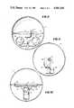
- FIG. 1is a perspective view of the spherical vehicle of the present invention
- FIG. 2is an enlarged view of the vehicle taken along line 2--2 of FIG. 1;
- FIG. 3is a view taken along line 3--3 of FIG. 2;
- FIG. 4is a view taken along line 4--4 of FIG. 2;
- FIG. 5is a side elevational view partly in section of an embodiment of the present invention illustrating the details of construction for remotely controlling the steering and speed system;
- FIG. 6is a fragmentary view taken along line 6--6 of FIG. 5;
- FIG. 7is a schematic of the remote control system employed in the embodiment of FIGS. 5 and 6;
- FIG. 8is a side elevational view partly in section of another embodiment of the present invention.
- FIG. 9is a side elevational view partly in section of yet another embodiment of the present invention.
- FIG. 10is a front elevational view partly in section of the embodiment shown in FIG. 9.
- the spherical vehicle 1 of the present inventionis adapted to roll on a supporting surface 2 and includes a spherical shell 3 having a removable top portion 4 which facilitates access to the interior of the shell containing the driving and steering components shown in FIG. 2.
- the drive assemblycomprises a shaft or axle 5 extending diametrically across the interior of the shell and having its ends rigidly secured to the inner wall thereof.
- a gear 6is secured to the shaft 5 and is adapted to be driven by a pinion gear 7 connected to the drive shaft of a motor 8.
- the motor 8is mounted on a frame assembly 9 journaled on the shaft 5 by suitable bearings 10 and collars 11 are secured to the shaft 5 to keep the frame 9 centered on the shaft 5.
- the pinion 7When the motor 8 is energized, the pinion 7 will drive gear 6 which in turn drives the axle 5 to thereby cause the spherical vehicle 1 to roll on a supporting surface. Since the frame 9 is journaled on the axle 5, it will not rotate with the axle but will remain oriented in a vertical plane.
- the steering assembly for the vehiclecomprises a pendulum arm 12 pivotally connected as at 13 to the frame 9, the lower end of the arm 12 having a mass 14 connected thereto, the center of the mass being in the plane containing the axle 5.
- a servo motor 15is also mounted on the pendulum arm 12 and as will be seen in FIG. 3, a gear 16 is connected to the servo motor drive shaft and meshes with a gear segment 17 integrally connected to the frame 9 and depending therefrom.
- the gear 16 meshing with gear segment 17will cause the pendulum 12, 14 to move in the direction of the arrows, depending upon the direction of rotation of the servo motor drive shaft, to thereby shift the center of gravity of the vehicle, whereby its direction of travel will be changed.
- the drive motor 8 and servo motor 15can be electric motors and the pendulum mass 14 can include batteries for energizing the motors.
- the speed of the motor 8 and the direction of rotation of the servo motor 15can be remotely controlled by a radio transmitter-receiver system wherein a receiver may be positioned within the spherical shell 3 and operatively connected to the servo motor 15 and drive motor 8, the receiver being responsive to signals from a transmitter actuated by an operator in a location remote from the vehicle.
- a radio transmitter-receiver systemwherein a receiver may be positioned within the spherical shell 3 and operatively connected to the servo motor 15 and drive motor 8, the receiver being responsive to signals from a transmitter actuated by an operator in a location remote from the vehicle.
- FIGS. 5 and 6which is similar to the embodiment shown in FIGS. 2 and 3 in that the motor 8 is mounted on the frame 9 which is journaled on the axle 5 driven by gear 6 meshing with drive pinion 7.
- the pendulum arm 12includes a pair of servo motors 15 mounted thereon and, instead of the pendulum pivot 13 and gear segment 17 shown in
- the drive shafts 18 of the servo motors 15are integrally connected to a pair of plates 19 rigidly connected to the frame 9; thus, the servo motor drive shafts 18 form the pivot point for the pendulum arm 12.
- the remaining components of the control system within the vehicleare mounted on the pendulum arm or frame 12 and include a receiver 20, a speed controller 21, speed control power drive 22, drive motor batteries 23, and receiver and servo motor batteries 24, the control system being completed by a transmitter 25 actuated by a person outside the vehicle.
- the components employed in the radio control system for steering the vehicle of the present inventionare standard components used today for the remote control of toy vehicles.
- FIG. 8Another embodiment for steering the vehicle by changing the center of gravity is illustrated in FIG. 8 wherein a pair of receptacles 26, 27 containing a fluid 28 are suspended from the frame 9.
- a pipe 29extends between the receptacles and includes a motor driven pump assembly 30, whereby the fluid can be transferred from one receptacle to another, to thereby change the center of gravity of the vehicle and thus the direction of travel thereof.
- the radio control system described in connection with the embodiment of FIGS. 5 and 6can also be used to control the drive motor 8 and motor pump assembly 30.
- the concept of continuously steering a spherical vehicle while it is rolling on a supporting surfacecan also be employed when the spherical shell 3 is made large enough to accommodate a person, as shown in FIGS. 9 and 10.
- the pendulum arm 12is pivotally connected to the frame as at 13.
- a suitable chair or bucket seat 31 having a tubular frameis rigidly connected to the lower end of the arm.
- An arcuate frame 32is secured to the frame 9 and depends therefrom to form a handle for a person 33 seated in the chair 31.
- the drive motor 8 and pulley-belt drive assembly 34are positioned outboard of the center of the sphere; accordingly, a conterweight 35 is secured to the opposite end of the frame 9.
- the motor 8 and associated pulley-belt drive assembly 34drives axle 5 to cause the sphere 3 to roll on a supporting surface.
- Steering of the vehicleis accomplished by the operator 33 grasping the arcuate handle 32 and passing it hand-over-hand to cause the pendulum arm 12 to move about pivot 13 to thereby change the center of gravity of the vehicle.
- the mass for the pendulumis provided by the chair 31, the operator 33 and the motor power source 36 which can be batteries if the motor 8 is electric or fuel, if the motor is an internal combustion engine.
- the shell 3 in this embodimentwould either be transparent or of an open framework construction to afford the operator clear visibility.
Landscapes
- Toys (AREA)
Abstract
Description
Spherical vehicles of the type having a drive shaft fixed at its opposite ends to the interior wall of a spherical shell and driven by a motor and gear assembly operatively connected to the drive shaft are known, as evidenced by U.S. Pat. Nos. 819,609 to Shorthcuse dated May 1, 1906; 2,949,696 to Easterling dated Aug. 23, 1960; and 2,949,697 to Licitis dated Aug. 23, 1960. Patent 819,609 further discloses the concept of suspending a mass from the drive shaft and manually inclining the mass to the axis of the shaft to cause the spherical member to travel in a curved path.
Heretofore, the spherical vehicles noted above either had no provision for steering the vehicle, or in the case of the Shorthcuse vehicle, the direction of travel is controlled by manually moving the mass to thereby maintain the vehicle in a fixed direction of travel until the vehicle is stopped and the mass is manually shifted to another position, whereby the vehicle will roll in another fixed direction of travel.
After considerable research and experimentation, the spherical vehicle of the present invention has been devised wherein a steering system is provided which can be continuously controlled to determine the direction of travel of the spherical vehicle while it is rolling on a supporting surface.
In one embodiment, the steering of the vehicle is remotely controlled by signals from a transmitter to a receiver and associated servo motors, speed controllers and batteries mounted within the spherical vehicle. In another embodiment, the steering is controlled by pumping fluid between two chambers mounted within the vehicle to thereby change the center of gravity of the vehicle. In yet another embodiment, the suspended mass includes a person seated in the vehicle whereby the center of gravity and hence direction of travel is manually controlled.
FIG. 1 is a perspective view of the spherical vehicle of the present invention;
FIG. 2 is an enlarged view of the vehicle taken alongline 2--2 of FIG. 1;
FIG. 3 is a view taken alongline 3--3 of FIG. 2;
FIG. 4 is a view taken alongline 4--4 of FIG. 2;
FIG. 5 is a side elevational view partly in section of an embodiment of the present invention illustrating the details of construction for remotely controlling the steering and speed system;
FIG. 6 is a fragmentary view taken alongline 6--6 of FIG. 5;
FIG. 7 is a schematic of the remote control system employed in the embodiment of FIGS. 5 and 6;
FIG. 8 is a side elevational view partly in section of another embodiment of the present invention;
FIG. 9 is a side elevational view partly in section of yet another embodiment of the present invention; and
FIG. 10 is a front elevational view partly in section of the embodiment shown in FIG. 9.
Referring to the drawings and more particularly to FIG. 1 thereof, the spherical vehicle 1 of the present invention is adapted to roll on a supportingsurface 2 and includes aspherical shell 3 having a removabletop portion 4 which facilitates access to the interior of the shell containing the driving and steering components shown in FIG. 2. The drive assembly comprises a shaft oraxle 5 extending diametrically across the interior of the shell and having its ends rigidly secured to the inner wall thereof. Agear 6 is secured to theshaft 5 and is adapted to be driven by apinion gear 7 connected to the drive shaft of amotor 8. Themotor 8 is mounted on aframe assembly 9 journaled on theshaft 5 bysuitable bearings 10 andcollars 11 are secured to theshaft 5 to keep theframe 9 centered on theshaft 5. When themotor 8 is energized, thepinion 7 will drivegear 6 which in turn drives theaxle 5 to thereby cause the spherical vehicle 1 to roll on a supporting surface. Since theframe 9 is journaled on theaxle 5, it will not rotate with the axle but will remain oriented in a vertical plane.
The steering assembly for the vehicle comprises apendulum arm 12 pivotally connected as at 13 to theframe 9, the lower end of thearm 12 having amass 14 connected thereto, the center of the mass being in the plane containing theaxle 5. Aservo motor 15 is also mounted on thependulum arm 12 and as will be seen in FIG. 3, agear 16 is connected to the servo motor drive shaft and meshes with agear segment 17 integrally connected to theframe 9 and depending therefrom. By this construction and arrangement, when theservo motor 15 is energized, thegear 16 meshing withgear segment 17 will cause thependulum drive motor 8 andservo motor 15 can be electric motors and thependulum mass 14 can include batteries for energizing the motors.
The speed of themotor 8 and the direction of rotation of theservo motor 15 can be remotely controlled by a radio transmitter-receiver system wherein a receiver may be positioned within thespherical shell 3 and operatively connected to theservo motor 15 anddrive motor 8, the receiver being responsive to signals from a transmitter actuated by an operator in a location remote from the vehicle. Such an arrangement is shown in FIGS. 5 and 6, which is similar to the embodiment shown in FIGS. 2 and 3 in that themotor 8 is mounted on theframe 9 which is journaled on theaxle 5 driven bygear 6 meshing withdrive pinion 7. Thependulum arm 12 includes a pair ofservo motors 15 mounted thereon and, instead of thependulum pivot 13 andgear segment 17 shown in FIG. 2, thedrive shafts 18 of theservo motors 15 are integrally connected to a pair ofplates 19 rigidly connected to theframe 9; thus, the servomotor drive shafts 18 form the pivot point for thependulum arm 12. The remaining components of the control system within the vehicle are mounted on the pendulum arm orframe 12 and include areceiver 20, aspeed controller 21, speedcontrol power drive 22, drivemotor batteries 23, and receiver andservo motor batteries 24, the control system being completed by atransmitter 25 actuated by a person outside the vehicle. The components employed in the radio control system for steering the vehicle of the present invention are standard components used today for the remote control of toy vehicles.
Another embodiment for steering the vehicle by changing the center of gravity is illustrated in FIG. 8 wherein a pair ofreceptacles fluid 28 are suspended from theframe 9. Apipe 29 extends between the receptacles and includes a motor drivenpump assembly 30, whereby the fluid can be transferred from one receptacle to another, to thereby change the center of gravity of the vehicle and thus the direction of travel thereof. It will be understood by those skilled in the art that the radio control system described in connection with the embodiment of FIGS. 5 and 6 can also be used to control thedrive motor 8 andmotor pump assembly 30.
While the embodiments of the vehicle of the present invention described hereinabove in connection with FIGS. 2 to 8 have been concerned with the remote control of the vehicle, the concept of continuously steering a spherical vehicle while it is rolling on a supporting surface can also be employed when thespherical shell 3 is made large enough to accommodate a person, as shown in FIGS. 9 and 10. In this embodiment, thependulum arm 12 is pivotally connected to the frame as at 13. A suitable chair orbucket seat 31 having a tubular frame is rigidly connected to the lower end of the arm. Anarcuate frame 32 is secured to theframe 9 and depends therefrom to form a handle for aperson 33 seated in thechair 31. Thedrive motor 8 and pulley-belt drive assembly 34 are positioned outboard of the center of the sphere; accordingly, a conterweight 35 is secured to the opposite end of theframe 9. In use, themotor 8 and associated pulley-belt drive assembly 34 drivesaxle 5 to cause thesphere 3 to roll on a supporting surface. Steering of the vehicle is accomplished by theoperator 33 grasping thearcuate handle 32 and passing it hand-over-hand to cause thependulum arm 12 to move aboutpivot 13 to thereby change the center of gravity of the vehicle. The mass for the pendulum is provided by thechair 31, theoperator 33 and themotor power source 36 which can be batteries if themotor 8 is electric or fuel, if the motor is an internal combustion engine. Theshell 3 in this embodiment would either be transparent or of an open framework construction to afford the operator clear visibility.
It is to be understood that the forms of the invention herewith shown and described are to be taken as preferred examples of the same, and that various changes in the shape, size and arrangement of parts may be resorted to, without departing from the spirit of the invention or scope of the subjoined claims.
Claims (9)
1. A spherical vehicle control system comprising, a spherical shell adapted to roll on a supporting surface, an axle extending diametrically across the interior of said shell, the ends of said axle being rigidly connected to the inner surface of said shell, frame means mounted on said axle, motor drive means mounted on said frame means and operatively connected to said axle for rotating said axle and associated spherical shell to thereby cause said shell to roll on a supporting surface, said frame means being journaled on said axle whereby said frame means remains in a vertical plane during rotation of said shell, mass means, means suspending said mass means from said frame means so that it is movable in a plane containing said axle, and control means operatively connected to said mass means for changing the position of said mass means by moving it toward one end of said axle or toward the other end thereof during the rolling motion of said shell, to thereby shift the center of gravity of said shell, whereby continuous steering of the vehicle is accomplished during the rolling thereof.
2. A sperical vehicle control system according to claim 1, wherein the motor drive means comprises a motor mounted on said frame, a gear mounted on the output shaft of said motor, and a gear secured to said axle meshing with said motor pinion gear.
3. A spherical vehicle control system according to claim 1, wherein the motor drive means comprises a motor mounted on said frame, and a pulley-belt drive assembly mounted between said motor and said axle.
4. A spherical vehicle control system according to claim 1, wherein the mass means comprises, a pendulum connected to said frame means, said pendulum including an arm pivotally connected at one end to said frame means and weight means mounted on the opposite end of said arm, and servomotor means mounted on said pendulum arm, said servomotor means having drive means operatively connecting it to said frame means, whereby upon actuation of said servomotor means the weight means is caused to move in an arcuate path about the pivotal connection of said arm.
5. A spherical vehicle control system according to claim 4, wherein said drive means includes a gear segment suspended from said frame means, a drive gear connected to the servomotor means drive shaft and meshing with said gear segment.
6. A spherical vehicle control system according to claim 4, the motor drive means including an electric motor and the servomotor means comprises at least one electric motor, and the weight means includes batteries for the servomotor means and electric drive motor means.
7. A spherical vehicle control system according to claim 1, wherein the mass means comprises a pair of fluid-containing receptacles suspended from said frame means, a fluid transfer pipe extending between said receptacles, and a pump assembly connected to said pipe for transferring fluid from one receptacle to another.
8. A spherical vehicle control system according to claim 4, wherein the servomotor means comprises a pair of oppositely facing servomotors, each servomotor having a drive shaft fixedly connected to said frame means, said servomotor drive shafts forming the pivotal connection of said pendulum arm to said frame means.
9. A spherical vehicle control system according to claim 6, wherein the control means comprises a radio control system including a receiver mounted on said pendulum arm, said receiver being electrically connected to said servomotor means, a speed control power drive mounted on said pendulum arm and connected to said electric drive motor, and a speed controller mounted on said pendulum arm and connected to said receiver and said speed control power drive, and a transmitter for sending signals to said receiver from a remote location, whereby the speed and direction of travel of the spherical vehicle can be remotely controlled.
Priority Applications (1)
| Application Number | Priority Date | Filing Date | Title |
|---|---|---|---|
| US06/460,930US4501569A (en) | 1983-01-25 | 1983-01-25 | Spherical vehicle control system |
Applications Claiming Priority (1)
| Application Number | Priority Date | Filing Date | Title |
|---|---|---|---|
| US06/460,930US4501569A (en) | 1983-01-25 | 1983-01-25 | Spherical vehicle control system |
Publications (1)
| Publication Number | Publication Date |
|---|---|
| US4501569Atrue US4501569A (en) | 1985-02-26 |
Family
ID=23830604
Family Applications (1)
| Application Number | Title | Priority Date | Filing Date |
|---|---|---|---|
| US06/460,930Expired - LifetimeUS4501569A (en) | 1983-01-25 | 1983-01-25 | Spherical vehicle control system |
Country Status (1)
| Country | Link |
|---|---|
| US (1) | US4501569A (en) |
Cited By (60)
| Publication number | Priority date | Publication date | Assignee | Title |
|---|---|---|---|---|
| US4601675A (en)* | 1984-05-25 | 1986-07-22 | Robinson Donald E | Mechanized toy ball |
| US4726800A (en)* | 1985-05-22 | 1988-02-23 | Shinsei Kogyo Co., Ltd. | Radio-controllable spherical toy vehicle |
| US4729446A (en)* | 1985-10-31 | 1988-03-08 | Sefton John S | Mobile sphere |
| US4813907A (en)* | 1986-05-05 | 1989-03-21 | Tiger Electronic Sales, Ltd. | Toy vehicle with graphics display |
| GB2239636A (en)* | 1989-12-28 | 1991-07-10 | Michael John Leigh Chapman | Self-propelled roll-about vehicle with hollow shell |
| US5041051A (en)* | 1990-02-21 | 1991-08-20 | Sonesson Harald V | Spheroid shaped toy vehicle with internal radio controlled steering and driving means |
| US5297981A (en)* | 1993-02-04 | 1994-03-29 | The Ertl Company, Inc. | Self-propelled bouncing ball |
| US5439408A (en)* | 1994-04-26 | 1995-08-08 | Wilkinson; William T. | Remote controlled movable ball amusement device |
| US5533214A (en)* | 1990-05-04 | 1996-07-09 | Graham; Wayne B. | Sheet roll up |
| USD375986S (en) | 1995-09-05 | 1996-11-26 | William T. Wilkinson | Remote controlled movable ball amusement device |
| US5692946A (en)* | 1996-01-11 | 1997-12-02 | Ku; Wang-Mine | Spherical steering toy |
| US5871386A (en)* | 1997-07-25 | 1999-02-16 | William T. Wilkinson | Remote controlled movable ball amusement device |
| US5890240A (en)* | 1990-05-04 | 1999-04-06 | Graham; Wayne B. | Sheet roll up |
| US5893791A (en)* | 1997-06-02 | 1999-04-13 | Wilkinson; William T. | Remote controlled rolling toy |
| WO1999030876A1 (en)* | 1997-12-16 | 1999-06-24 | Board Of Trustees Operating Michigan State University | Spherical mobile robot |
| US6298934B1 (en) | 2000-03-27 | 2001-10-09 | David Shteingold | Spherical vehicle |
| US6378634B1 (en)* | 2000-11-28 | 2002-04-30 | Xerox Corporation | Tracking device |
| US6402630B1 (en) | 2001-04-06 | 2002-06-11 | Nelson Tyler | Bowling ball |
| US6569025B1 (en)* | 2002-03-07 | 2003-05-27 | Nelson Tyler | Bowling ball |
| US6571415B2 (en) | 2000-12-01 | 2003-06-03 | The Hoover Company | Random motion cleaner |
| US20030126701A1 (en)* | 2000-10-30 | 2003-07-10 | Turbjorn Aasen | Mobile robot |
| US20040192163A1 (en)* | 2003-03-29 | 2004-09-30 | Siegel Robert Paul | Remotely controlled steerable ball |
| US6937125B1 (en) | 1999-10-18 | 2005-08-30 | William W. French | Self rotating display spherical device |
| DE202005002879U1 (en)* | 2005-02-21 | 2006-04-06 | Raidt, Alexander | Circular wheel-shaped ride for one or more persons for use in amusement parks has lifting device raising it from starting point to higher level |
| USD529967S1 (en) | 2005-02-09 | 2006-10-10 | Mattel, Inc. | Toy vehicle and parts thereof |
| US7217170B2 (en) | 2004-10-26 | 2007-05-15 | Mattel, Inc. | Transformable toy vehicle |
| US20070215394A1 (en)* | 2006-03-15 | 2007-09-20 | Sun Hanxu | Spherical walking robot |
| USD566788S1 (en) | 2007-01-04 | 2008-04-15 | Mattel, Inc. | Transforming toy vehicle |
| US20080097644A1 (en)* | 2004-11-02 | 2008-04-24 | Rotundus Ab | Ball Robot |
| USD569924S1 (en) | 2005-02-09 | 2008-05-27 | Mattel, Inc. | Chassis part of a toy vehicle |
| US20090188729A1 (en)* | 2008-01-24 | 2009-07-30 | Benjamin Lawrence Berry | Track sphere wheel assembly |
| CN100584689C (en)* | 2008-01-10 | 2010-01-27 | 马启义 | a spherical boat |
| CN101982304A (en)* | 2010-09-18 | 2011-03-02 | 中北大学 | Inner driving spherical robot |
| US20110155481A1 (en)* | 2008-09-17 | 2011-06-30 | Peter Mondl | Vehicle |
| US20120024648A1 (en)* | 2010-07-28 | 2012-02-02 | Chi Mei Communication Systems, Inc. | Portable device |
| US8197298B2 (en) | 2006-05-04 | 2012-06-12 | Mattel, Inc. | Transformable toy vehicle |
| US8210289B1 (en)* | 2010-01-12 | 2012-07-03 | The United States Of America, As Represented By The Secretary Of The Navy | High velocity microbot |
| US20150165336A1 (en)* | 2013-12-12 | 2015-06-18 | Beatbots, LLC | Robot |
| US20150245593A1 (en)* | 2014-03-03 | 2015-09-03 | Jason E. O'mara | Autonomous motion device, system, and method |
| US20150274000A1 (en)* | 2014-03-31 | 2015-10-01 | Paha Designs,Llc | Low gravity all-surface vehicle |
| US20150338215A1 (en)* | 2013-12-23 | 2015-11-26 | Tilak SRINIVASAN | Orientation indication device |
| CN105196814A (en)* | 2015-10-13 | 2015-12-30 | 宋建国 | Ball-shaped rolling land and water scooter |
| CN106828831A (en)* | 2017-01-19 | 2017-06-13 | 河海大学 | A kind of rolling into based on built-in driving principle is swum hybrid submersible of dwelling more |
| US20180043838A1 (en)* | 2016-08-12 | 2018-02-15 | Spin Master, Ltd. | Spherical mobile robot with pivoting head |
| US20180043952A1 (en)* | 2016-08-12 | 2018-02-15 | Spin Master Ltd. | Spherical mobile robot with shifting weight steering |
| US9968864B2 (en) | 2016-03-21 | 2018-05-15 | Sphero, Inc. | Multi-body self propelled device with magnetic yaw control |
| US10010786B1 (en) | 2017-08-05 | 2018-07-03 | Simon Basyuk | Roll and stand-up toy and a game using the same |
| US10065693B2 (en) | 2014-03-31 | 2018-09-04 | Paha Designs, Llc | Low gravity all-surface vehicle |
| US10118104B1 (en) | 2017-08-05 | 2018-11-06 | Simon Basyuk | Roll and stand-up toy and a game using the same |
| CN109173281A (en)* | 2018-09-26 | 2019-01-11 | 广州市华秦游乐设备有限公司 | A kind of spherical shape dodgem |
| US10179508B2 (en) | 2014-03-31 | 2019-01-15 | Paha Designs, Llc | Low gravity all-surface vehicle |
| WO2019064776A1 (en)* | 2017-09-29 | 2019-04-04 | 株式会社バンダイ | Robotic device |
| US10308134B2 (en) | 2017-03-02 | 2019-06-04 | The Goodyear Tire & Rubber Company | Spherical wheel/tire assembly |
| US10421192B2 (en) | 2011-04-11 | 2019-09-24 | Massachusetts Institute Of Technology | Apparatus and method of wireless underwater inspection robot for nuclear power plants |
| US10543874B2 (en) | 2017-05-17 | 2020-01-28 | Paha Designs, Llc | Low gravity all-surface vehicle and stabilized mount system |
| US20210205983A1 (en)* | 2020-01-03 | 2021-07-08 | Shenzhen Institute Of Artificial Intelligence And Robotics For Society | Self-reconfigurable robot module and self-reconfigurable robot |
| CN114889720A (en)* | 2022-06-15 | 2022-08-12 | 齐福永 | Desert walking aid equipment |
| US12296665B2 (en) | 2021-08-13 | 2025-05-13 | Azak Inc. | High efficiency electric motor |
| US12370881B1 (en) | 2020-10-05 | 2025-07-29 | Azak Inc. | Wheel for use in a low gravity vehicle |
| US12441135B2 (en) | 2021-12-29 | 2025-10-14 | Azak Inc. | Quick coupling for wheel-to-vehicle attachment |
Citations (5)
| Publication number | Priority date | Publication date | Assignee | Title |
|---|---|---|---|---|
| US933623A (en)* | 1909-03-15 | 1909-09-07 | Brown Paul W | Mechanical toy. |
| US1033077A (en)* | 1910-03-03 | 1912-07-23 | Joseph Gerrish Ayers Jr | Motor-propelled ball. |
| US1039617A (en)* | 1912-06-04 | 1912-09-24 | Pardon Bentley Tyler | Toy. |
| US3777835A (en)* | 1972-01-14 | 1973-12-11 | R Bourne | One-wheel vehicle |
| US4391224A (en)* | 1981-07-27 | 1983-07-05 | Adler Harold A | Animal amusement apparatus |
- 1983
- 1983-01-25USUS06/460,930patent/US4501569A/ennot_activeExpired - Lifetime
Patent Citations (5)
| Publication number | Priority date | Publication date | Assignee | Title |
|---|---|---|---|---|
| US933623A (en)* | 1909-03-15 | 1909-09-07 | Brown Paul W | Mechanical toy. |
| US1033077A (en)* | 1910-03-03 | 1912-07-23 | Joseph Gerrish Ayers Jr | Motor-propelled ball. |
| US1039617A (en)* | 1912-06-04 | 1912-09-24 | Pardon Bentley Tyler | Toy. |
| US3777835A (en)* | 1972-01-14 | 1973-12-11 | R Bourne | One-wheel vehicle |
| US4391224A (en)* | 1981-07-27 | 1983-07-05 | Adler Harold A | Animal amusement apparatus |
Cited By (91)
| Publication number | Priority date | Publication date | Assignee | Title |
|---|---|---|---|---|
| US4601675A (en)* | 1984-05-25 | 1986-07-22 | Robinson Donald E | Mechanized toy ball |
| US4726800A (en)* | 1985-05-22 | 1988-02-23 | Shinsei Kogyo Co., Ltd. | Radio-controllable spherical toy vehicle |
| US4729446A (en)* | 1985-10-31 | 1988-03-08 | Sefton John S | Mobile sphere |
| US4813907A (en)* | 1986-05-05 | 1989-03-21 | Tiger Electronic Sales, Ltd. | Toy vehicle with graphics display |
| GB2239636B (en)* | 1989-12-28 | 1994-03-02 | Michael John Leigh Chapman | Self propelled roll-about |
| GB2239636A (en)* | 1989-12-28 | 1991-07-10 | Michael John Leigh Chapman | Self-propelled roll-about vehicle with hollow shell |
| US5041051A (en)* | 1990-02-21 | 1991-08-20 | Sonesson Harald V | Spheroid shaped toy vehicle with internal radio controlled steering and driving means |
| US5533214A (en)* | 1990-05-04 | 1996-07-09 | Graham; Wayne B. | Sheet roll up |
| US5890240A (en)* | 1990-05-04 | 1999-04-06 | Graham; Wayne B. | Sheet roll up |
| US5297981A (en)* | 1993-02-04 | 1994-03-29 | The Ertl Company, Inc. | Self-propelled bouncing ball |
| US5439408A (en)* | 1994-04-26 | 1995-08-08 | Wilkinson; William T. | Remote controlled movable ball amusement device |
| USD375986S (en) | 1995-09-05 | 1996-11-26 | William T. Wilkinson | Remote controlled movable ball amusement device |
| US5692946A (en)* | 1996-01-11 | 1997-12-02 | Ku; Wang-Mine | Spherical steering toy |
| US5893791A (en)* | 1997-06-02 | 1999-04-13 | Wilkinson; William T. | Remote controlled rolling toy |
| US5871386A (en)* | 1997-07-25 | 1999-02-16 | William T. Wilkinson | Remote controlled movable ball amusement device |
| US6066026A (en)* | 1997-07-25 | 2000-05-23 | William T. Wilkinson | Remote controlled simulated tire amusement device |
| WO1999030876A1 (en)* | 1997-12-16 | 1999-06-24 | Board Of Trustees Operating Michigan State University | Spherical mobile robot |
| US6289263B1 (en) | 1997-12-16 | 2001-09-11 | Board Of Trustees Operating Michigan State University | Spherical mobile robot |
| US6937125B1 (en) | 1999-10-18 | 2005-08-30 | William W. French | Self rotating display spherical device |
| US6298934B1 (en) | 2000-03-27 | 2001-10-09 | David Shteingold | Spherical vehicle |
| US6938298B2 (en)* | 2000-10-30 | 2005-09-06 | Turbjorn Aasen | Mobile cleaning robot for floors |
| US20030126701A1 (en)* | 2000-10-30 | 2003-07-10 | Turbjorn Aasen | Mobile robot |
| US6378634B1 (en)* | 2000-11-28 | 2002-04-30 | Xerox Corporation | Tracking device |
| EP1211415A3 (en)* | 2000-11-28 | 2004-01-28 | Xerox Corporation | Tracking device |
| US20050235444A1 (en)* | 2000-12-01 | 2005-10-27 | Gerber Douglas E | Random motion cleaner |
| US7254859B2 (en) | 2000-12-01 | 2007-08-14 | The Hoover Company | Random motion cleaner |
| US7207081B2 (en)* | 2000-12-01 | 2007-04-24 | The Hoover Company | Random motion cleaner |
| US6571415B2 (en) | 2000-12-01 | 2003-06-03 | The Hoover Company | Random motion cleaner |
| US20030205242A1 (en)* | 2000-12-01 | 2003-11-06 | Gerber Douglas E. | Random motion cleaner |
| US6402630B1 (en) | 2001-04-06 | 2002-06-11 | Nelson Tyler | Bowling ball |
| US6569025B1 (en)* | 2002-03-07 | 2003-05-27 | Nelson Tyler | Bowling ball |
| US6855028B2 (en)* | 2003-03-29 | 2005-02-15 | Robert P Siegel | Remotely controlled steerable ball |
| US20040192163A1 (en)* | 2003-03-29 | 2004-09-30 | Siegel Robert Paul | Remotely controlled steerable ball |
| US7217170B2 (en) | 2004-10-26 | 2007-05-15 | Mattel, Inc. | Transformable toy vehicle |
| US20070210540A1 (en)* | 2004-10-26 | 2007-09-13 | Mattel, Inc. | Transformable toy vehicle |
| US7794300B2 (en) | 2004-10-26 | 2010-09-14 | Mattel, Inc. | Transformable toy vehicle |
| US8099189B2 (en)* | 2004-11-02 | 2012-01-17 | Rotundus Ab | Ball robot |
| US20080097644A1 (en)* | 2004-11-02 | 2008-04-24 | Rotundus Ab | Ball Robot |
| USD529967S1 (en) | 2005-02-09 | 2006-10-10 | Mattel, Inc. | Toy vehicle and parts thereof |
| USD569924S1 (en) | 2005-02-09 | 2008-05-27 | Mattel, Inc. | Chassis part of a toy vehicle |
| USD584366S1 (en) | 2005-02-09 | 2009-01-06 | Mattel, Inc. | Vaned wheel parts of a toy vehicle |
| DE202005002879U1 (en)* | 2005-02-21 | 2006-04-06 | Raidt, Alexander | Circular wheel-shaped ride for one or more persons for use in amusement parks has lifting device raising it from starting point to higher level |
| US7726422B2 (en)* | 2006-03-15 | 2010-06-01 | Beijing University Of Posts & Telecommunications | Spherical walking robot |
| US20070215394A1 (en)* | 2006-03-15 | 2007-09-20 | Sun Hanxu | Spherical walking robot |
| US8197298B2 (en) | 2006-05-04 | 2012-06-12 | Mattel, Inc. | Transformable toy vehicle |
| USD566788S1 (en) | 2007-01-04 | 2008-04-15 | Mattel, Inc. | Transforming toy vehicle |
| CN100584689C (en)* | 2008-01-10 | 2010-01-27 | 马启义 | a spherical boat |
| US20090188729A1 (en)* | 2008-01-24 | 2009-07-30 | Benjamin Lawrence Berry | Track sphere wheel assembly |
| US20110155481A1 (en)* | 2008-09-17 | 2011-06-30 | Peter Mondl | Vehicle |
| US8499862B2 (en) | 2008-09-17 | 2013-08-06 | Peter Mondl | Spherical vehicle |
| US8210289B1 (en)* | 2010-01-12 | 2012-07-03 | The United States Of America, As Represented By The Secretary Of The Navy | High velocity microbot |
| US20120024648A1 (en)* | 2010-07-28 | 2012-02-02 | Chi Mei Communication Systems, Inc. | Portable device |
| CN101982304A (en)* | 2010-09-18 | 2011-03-02 | 中北大学 | Inner driving spherical robot |
| CN101982304B (en)* | 2010-09-18 | 2012-09-12 | 中北大学 | Inner driving spherical robot |
| US10421192B2 (en) | 2011-04-11 | 2019-09-24 | Massachusetts Institute Of Technology | Apparatus and method of wireless underwater inspection robot for nuclear power plants |
| US9358475B2 (en)* | 2013-12-12 | 2016-06-07 | Beatbots, LLC | Robot |
| US20150165336A1 (en)* | 2013-12-12 | 2015-06-18 | Beatbots, LLC | Robot |
| US9664512B2 (en)* | 2013-12-23 | 2017-05-30 | Tilak SRINIVASAN | Orientation indication device |
| US20150338215A1 (en)* | 2013-12-23 | 2015-11-26 | Tilak SRINIVASAN | Orientation indication device |
| US20150245593A1 (en)* | 2014-03-03 | 2015-09-03 | Jason E. O'mara | Autonomous motion device, system, and method |
| US11040747B2 (en) | 2014-03-31 | 2021-06-22 | Paha Designs, Llc | Low gravity all-surface vehicle |
| US12054210B2 (en) | 2014-03-31 | 2024-08-06 | Azak Inc. | Low gravity all-surface vehicle |
| US10179508B2 (en) | 2014-03-31 | 2019-01-15 | Paha Designs, Llc | Low gravity all-surface vehicle |
| US20150274000A1 (en)* | 2014-03-31 | 2015-10-01 | Paha Designs,Llc | Low gravity all-surface vehicle |
| US9457647B2 (en)* | 2014-03-31 | 2016-10-04 | Paha Designs, Llc | Low gravity all-surface vehicle |
| US10065693B2 (en) | 2014-03-31 | 2018-09-04 | Paha Designs, Llc | Low gravity all-surface vehicle |
| CN105196814A (en)* | 2015-10-13 | 2015-12-30 | 宋建国 | Ball-shaped rolling land and water scooter |
| US10101739B2 (en) | 2016-03-21 | 2018-10-16 | Sphero, Inc. | Multi-body self propelled device with induction interface power transfer |
| US9968864B2 (en) | 2016-03-21 | 2018-05-15 | Sphero, Inc. | Multi-body self propelled device with magnetic yaw control |
| CN107719498A (en)* | 2016-08-12 | 2018-02-23 | 斯平玛斯特有限公司 | Spherical mobile robot with center of gravity transfer steering mechanism |
| US20180043952A1 (en)* | 2016-08-12 | 2018-02-15 | Spin Master Ltd. | Spherical mobile robot with shifting weight steering |
| US20180043838A1 (en)* | 2016-08-12 | 2018-02-15 | Spin Master, Ltd. | Spherical mobile robot with pivoting head |
| US10399616B2 (en)* | 2016-08-12 | 2019-09-03 | Spin Master Ltd. | Spherical mobile robot with pivoting head |
| WO2018133314A1 (en)* | 2017-01-19 | 2018-07-26 | 河海大学 | Rolling and floating combined amphibious vehicle based on internal drive principle |
| CN106828831A (en)* | 2017-01-19 | 2017-06-13 | 河海大学 | A kind of rolling into based on built-in driving principle is swum hybrid submersible of dwelling more |
| US10308134B2 (en) | 2017-03-02 | 2019-06-04 | The Goodyear Tire & Rubber Company | Spherical wheel/tire assembly |
| US10543874B2 (en) | 2017-05-17 | 2020-01-28 | Paha Designs, Llc | Low gravity all-surface vehicle and stabilized mount system |
| US12024236B2 (en) | 2017-05-17 | 2024-07-02 | Azak Inc. | Low gravity all-surface vehicle and stabilized mount system |
| US10010786B1 (en) | 2017-08-05 | 2018-07-03 | Simon Basyuk | Roll and stand-up toy and a game using the same |
| US10118104B1 (en) | 2017-08-05 | 2018-11-06 | Simon Basyuk | Roll and stand-up toy and a game using the same |
| JP2019063266A (en)* | 2017-09-29 | 2019-04-25 | 株式会社バンダイ | Robot equipment |
| WO2019064776A1 (en)* | 2017-09-29 | 2019-04-04 | 株式会社バンダイ | Robotic device |
| CN109173281B (en)* | 2018-09-26 | 2023-11-28 | 广州市华秦游乐设备有限公司 | Spherical bumper car |
| CN109173281A (en)* | 2018-09-26 | 2019-01-11 | 广州市华秦游乐设备有限公司 | A kind of spherical shape dodgem |
| US20210205983A1 (en)* | 2020-01-03 | 2021-07-08 | Shenzhen Institute Of Artificial Intelligence And Robotics For Society | Self-reconfigurable robot module and self-reconfigurable robot |
| US12023809B2 (en)* | 2020-01-03 | 2024-07-02 | Shenzhen Institute Of Artificial Intelligence And Robotics For Society | Self-reconfigurable robot module and self-reconfigurable robot |
| US12370881B1 (en) | 2020-10-05 | 2025-07-29 | Azak Inc. | Wheel for use in a low gravity vehicle |
| US12296665B2 (en) | 2021-08-13 | 2025-05-13 | Azak Inc. | High efficiency electric motor |
| US12441135B2 (en) | 2021-12-29 | 2025-10-14 | Azak Inc. | Quick coupling for wheel-to-vehicle attachment |
| CN114889720A (en)* | 2022-06-15 | 2022-08-12 | 齐福永 | Desert walking aid equipment |
| CN114889720B (en)* | 2022-06-15 | 2024-04-09 | 齐福永 | Desert helps capable equipment |
Similar Documents
| Publication | Publication Date | Title |
|---|---|---|
| US4501569A (en) | Spherical vehicle control system | |
| KR101200762B1 (en) | Remote-controlled fluttering object capable of flying forward in upright position | |
| US4897070A (en) | Two-wheeled motorized toy | |
| US4219957A (en) | Traveling toy | |
| US4785899A (en) | Vehicle with spherical-shaped wheels for steering and speed control purposes | |
| JP2003512227A (en) | Vehicle | |
| EP1954365B1 (en) | Toy vehicle | |
| CA2669934A1 (en) | Three wheeled toy vehicle | |
| CN212605739U (en) | A manta ray robot | |
| US4577528A (en) | Driving/turnaround device for a remote controlled toy vehicle | |
| US3364874A (en) | Driving mechanism for a vehicle | |
| JPS6341347B2 (en) | ||
| US2862332A (en) | Steering mechanism for toys | |
| CN113085459B (en) | Triphibian variant robot | |
| JP2003512226A (en) | Self-propelled drive wheels | |
| CN209667325U (en) | The fish humanoid robot that can be rided | |
| CN109250110A (en) | A kind of scenic spot flying robot | |
| US4034502A (en) | Wheeled toy | |
| CN112441200A (en) | Driving system and driving method for bionic fish underwater robot | |
| EP0304193B1 (en) | Rotating-brush washing apparatus | |
| US4127963A (en) | Toy drawing doll | |
| CA2073525C (en) | Propelling system for flying machine | |
| US2091845A (en) | Propelling device for watercraft and aircraft | |
| JPS6485846A (en) | Remote control device for rear view mirror | |
| CN2608083Y (en) | Ball structure vehicle |
Legal Events
| Date | Code | Title | Description |
|---|---|---|---|
| REMI | Maintenance fee reminder mailed | ||
| FPAY | Fee payment | Year of fee payment:4 | |
| SULP | Surcharge for late payment | ||
| FEPP | Fee payment procedure | Free format text:PETITION RELATED TO MAINTENANCE FEES FILED (ORIGINAL EVENT CODE: PMFP); ENTITY STATUS OF PATENT OWNER: SMALL ENTITY | |
| FEPP | Fee payment procedure | Free format text:PETITION RELATED TO MAINTENANCE FEES GRANTED (ORIGINAL EVENT CODE: PMFG); ENTITY STATUS OF PATENT OWNER: SMALL ENTITY | |
| FEPP | Fee payment procedure | Free format text:PETITION RELATED TO MAINTENANCE FEES FILED (ORIGINAL EVENT CODE: PMFP); ENTITY STATUS OF PATENT OWNER: SMALL ENTITY | |
| FEPP | Fee payment procedure | Free format text:PETITION RELATED TO MAINTENANCE FEES DENIED/DISMISSED (ORIGINAL EVENT CODE: PMFD); ENTITY STATUS OF PATENT OWNER: SMALL ENTITY | |
| FPAY | Fee payment | Year of fee payment:8 | |
| SULP | Surcharge for late payment | ||
| STCF | Information on status: patent grant | Free format text:PATENTED CASE | |
| FPAY | Fee payment | Year of fee payment:12 |