US4501152A - Temperature compensator for liquid filled pressure gauge - Google Patents
Temperature compensator for liquid filled pressure gaugeDownload PDFInfo
- Publication number
- US4501152A US4501152AUS06/473,829US47382983AUS4501152AUS 4501152 AUS4501152 AUS 4501152AUS 47382983 AUS47382983 AUS 47382983AUS 4501152 AUS4501152 AUS 4501152A
- Authority
- US
- United States
- Prior art keywords
- cover plate
- annulus
- diaphragm
- case
- pressure gauge
- Prior art date
- Legal status (The legal status is an assumption and is not a legal conclusion. Google has not performed a legal analysis and makes no representation as to the accuracy of the status listed.)
- Expired - Lifetime
Links
- 239000007788liquidSubstances0.000titleabstractdescription10
- 239000012530fluidSubstances0.000claimsdescription15
- 238000006073displacement reactionMethods0.000claimsdescription6
- 230000000694effectsEffects0.000claimsdescription2
- 238000000926separation methodMethods0.000claims1
- 238000010276constructionMethods0.000description11
- 238000009434installationMethods0.000description4
- 238000007789sealingMethods0.000description3
- 239000007787solidSubstances0.000description3
- 230000002093peripheral effectEffects0.000description2
- 239000004033plasticSubstances0.000description2
- 230000010349pulsationEffects0.000description2
- 230000029058respiratory gaseous exchangeEffects0.000description2
- 239000004743PolypropyleneSubstances0.000description1
- 230000002411adverseEffects0.000description1
- 238000009530blood pressure measurementMethods0.000description1
- 230000007797corrosionEffects0.000description1
- 238000005260corrosionMethods0.000description1
- 230000002708enhancing effectEffects0.000description1
- 238000004519manufacturing processMethods0.000description1
- 239000002184metalSubstances0.000description1
- ISWSIDIOOBJBQZ-UHFFFAOYSA-Nphenol groupChemical groupC1(=CC=CC=C1)OISWSIDIOOBJBQZ-UHFFFAOYSA-N0.000description1
- -1polypropylenePolymers0.000description1
- 229920001155polypropylenePolymers0.000description1
- 238000003466weldingMethods0.000description1
Images
Classifications
- G—PHYSICS
- G01—MEASURING; TESTING
- G01L—MEASURING FORCE, STRESS, TORQUE, WORK, MECHANICAL POWER, MECHANICAL EFFICIENCY, OR FLUID PRESSURE
- G01L19/00—Details of, or accessories for, apparatus for measuring steady or quasi-steady pressure of a fluent medium insofar as such details or accessories are not special to particular types of pressure gauges
- G01L19/14—Housings
Definitions
- the field of art to which the invention pertainsincludes the art of measuring and testing as directed to fluid pressure gauges having fluid pulsation dampening.
- gauge instruments and particularly pressure gauges or the like containing an oil fillhave been widely used and are commercially available from a variety of manufacturing sources. Specific reasons vary for selecting or requiring an oil filled gauge versus a dry or unfilled gauge but generally are attributed to either protecting the working mechanism against corrosion and/or system vibration or pulsation to which the instrument is subjected.
- Prior art exemplifying gauges of this sortare disclosed in U.S. Pat. Nos. 2,773,388; 3,080,758; 3,370,470; 3,712,138; 3,874,241; 3,938,393; 3,990,306; 3,701,284, and 4,214,466.
- a problem associated with liquid filled constructionsis the desirability to minimize case depth while providing both adequate compensation volume and pressure relieving capability in the event excessive overpressure is encountered from within the case.
- Diaphragms arranged to provide an enclosed air pockethave been utilized for this purpose, but because of slack or bowing of the diaphragm encountered after installation, the functional reliability of such prior art constructions has been less than desirable.
- a solutionhas not heretofore been known.
- the inventionrelates to gauge instruments and more specifically to gauge case constructions for a liquid filled pressure gauge affording enhanced reliability of temperature compensation for induced volume changes of the liquid fill while at the same time providing pressure relief capability in the event excess overpressures are encountered.
- An annulus extending laterally from the cover faceincludes a negative draft about its circumference for receiving the pretensioned diaphragm and enables diaphragm tension to be increased in the course of positioning the diaphragm in a friction fit within the case.
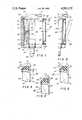
- FIG. 1is a sectional elevation partially exploded of a gauge casing in accordance with the invention in its pre-assembly relation;
- FIG. 2is a fragmentary sectional elevation of the gauge case of FIG. 1 in its post-assembly relation;
- FIGS. 3, 4 and 5are enlarged fragmentary sections of the encircled portion of FIG. 2 for alternate embodiments of the invention.
- FIGS. 1 and 2 of the drawingsthere is illustrated a more or less typical turret-shaped gauge casing 10 formed of phenolic or polypropylene or other commercially suitable plastic composition.
- the casingis of a solid front construction in which an intermediate wall 12 separates a front compartment 14 from a rear compartment 16 to which fluid fill (not shown) is supplied.
- a plurality of bolt bosses 18 spaced around the rear peripheryenable convenient mounting of the gauge in a variety of manners which are per se well known.
Landscapes
- Physics & Mathematics (AREA)
- General Physics & Mathematics (AREA)
- Measuring Fluid Pressure (AREA)
Abstract
Description
Claims (5)
Priority Applications (9)
| Application Number | Priority Date | Filing Date | Title |
|---|---|---|---|
| US06/473,829US4501152A (en) | 1983-03-09 | 1983-03-09 | Temperature compensator for liquid filled pressure gauge |
| NL8400750ANL8400750A (en) | 1983-03-09 | 1984-03-08 | TEMPERATURE COMPENSATOR FOR A FLUID-FILLED PRESSURE GAUGE. |
| CA000449172ACA1208037A (en) | 1983-03-09 | 1984-03-08 | Temperature compensator for liquid filled pressure gauge |
| FR8403654AFR2542445A1 (en) | 1983-03-09 | 1984-03-09 | TEMPERATURE COMPENSATOR FOR FLUID FILLER GAUGE |
| DE19843409137DE3409137A1 (en) | 1983-03-09 | 1984-03-09 | HEAT COMPENSATING DEVICE FOR LIQUID-FILLED PRESSURE MEASURING DEVICES |
| IT47837/84AIT1179166B (en) | 1983-03-09 | 1984-03-09 | TEMPERATURE COMPENSATION DEVICE FOR LIQUID FILLING PRESSURE GAUGES |
| BR8401094ABR8401094A (en) | 1983-03-09 | 1984-03-09 | FLUID MANOMETER |
| JP59045331AJPS59173728A (en) | 1983-03-09 | 1984-03-09 | Temperature compensation device for liquid filled pressure gage |
| GB08406202AGB2136127B (en) | 1983-03-09 | 1984-03-09 | Case for gauge instrument |
Applications Claiming Priority (1)
| Application Number | Priority Date | Filing Date | Title |
|---|---|---|---|
| US06/473,829US4501152A (en) | 1983-03-09 | 1983-03-09 | Temperature compensator for liquid filled pressure gauge |
Publications (1)
| Publication Number | Publication Date |
|---|---|
| US4501152Atrue US4501152A (en) | 1985-02-26 |
Family
ID=23881172
Family Applications (1)
| Application Number | Title | Priority Date | Filing Date |
|---|---|---|---|
| US06/473,829Expired - LifetimeUS4501152A (en) | 1983-03-09 | 1983-03-09 | Temperature compensator for liquid filled pressure gauge |
Country Status (9)
| Country | Link |
|---|---|
| US (1) | US4501152A (en) |
| JP (1) | JPS59173728A (en) |
| BR (1) | BR8401094A (en) |
| CA (1) | CA1208037A (en) |
| DE (1) | DE3409137A1 (en) |
| FR (1) | FR2542445A1 (en) |
| GB (1) | GB2136127B (en) |
| IT (1) | IT1179166B (en) |
| NL (1) | NL8400750A (en) |
Cited By (6)
| Publication number | Priority date | Publication date | Assignee | Title |
|---|---|---|---|---|
| US5399855A (en)* | 1993-12-16 | 1995-03-21 | Northrop Grumman Corporation | Atmospheric exclusion system having an expandable shroud and a non-elastic bladder |
| US6053043A (en)* | 1993-03-26 | 2000-04-25 | Navistar International Transportation Corp | Turn lock bezel for gauge extraction and retention |
| US6651507B1 (en) | 1998-05-15 | 2003-11-25 | Dresser, Inc. | Pressure gauge having a dampener mechanism |
| US6679122B2 (en) | 1998-05-15 | 2004-01-20 | Dresser, Inc. | Pressure gauge having a dampener mechanism with attachable housing |
| US6758097B2 (en) | 2001-11-30 | 2004-07-06 | Mija Industries | Pressure gauge spring |
| US11366035B2 (en)* | 2019-10-15 | 2022-06-21 | Anderson Instrument Co., Inc. | System and method for reducing thermal offset in a pressure gauge |
Families Citing this family (4)
| Publication number | Priority date | Publication date | Assignee | Title |
|---|---|---|---|---|
| DE8410848U1 (en)* | 1984-04-06 | 1984-08-02 | Alexander Wiegand Gmbh U. Co Armaturen- U. Manometerfabrik, 8763 Klingenberg | PLASTIC MANOMETER HOUSING |
| DE3521823A1 (en)* | 1985-06-01 | 1986-12-04 | F + R Förster & Rothmann GmbH, 7844 Neuenburg | Pressure-measuring device for pressure cookers, and method of calibrating it |
| US5012678A (en)* | 1990-08-15 | 1991-05-07 | Dwyer Struments, Inc. | Overpressure relief safety plug for pressure gauges |
| CN112240815A (en)* | 2019-07-01 | 2021-01-19 | 威卡亚力山大维甘德欧洲两合公司 | Instrument with flexible window cover |
Citations (4)
| Publication number | Priority date | Publication date | Assignee | Title |
|---|---|---|---|---|
| US2693896A (en)* | 1950-03-10 | 1954-11-09 | Acragage Corp | Pressure gauge case and closure |
| DE2249266A1 (en)* | 1972-10-07 | 1974-04-18 | Haenni & Cie Gmbh | HOUSING TO ACCOMMODATE A MEASURING MOVEMENT, IN PARTICULAR A POINTING MOVEMENT |
| US3938393A (en)* | 1973-12-28 | 1976-02-17 | Tempress A/S | Measuring instruments |
| US4051730A (en)* | 1976-05-20 | 1977-10-04 | H. O. Trerice Co. | Condition responsive indicating instrument |
Family Cites Families (1)
| Publication number | Priority date | Publication date | Assignee | Title |
|---|---|---|---|---|
| US4214486A (en)* | 1978-09-28 | 1980-07-29 | Dresser Industries, Inc. | Sealed casing for pressure gauge |
- 1983
- 1983-03-09USUS06/473,829patent/US4501152A/ennot_activeExpired - Lifetime
- 1984
- 1984-03-08NLNL8400750Apatent/NL8400750A/ennot_activeApplication Discontinuation
- 1984-03-08CACA000449172Apatent/CA1208037A/ennot_activeExpired
- 1984-03-09DEDE19843409137patent/DE3409137A1/ennot_activeWithdrawn
- 1984-03-09JPJP59045331Apatent/JPS59173728A/enactivePending
- 1984-03-09ITIT47837/84Apatent/IT1179166B/enactive
- 1984-03-09FRFR8403654Apatent/FR2542445A1/ennot_activeWithdrawn
- 1984-03-09BRBR8401094Apatent/BR8401094A/enunknown
- 1984-03-09GBGB08406202Apatent/GB2136127B/ennot_activeExpired
Patent Citations (4)
| Publication number | Priority date | Publication date | Assignee | Title |
|---|---|---|---|---|
| US2693896A (en)* | 1950-03-10 | 1954-11-09 | Acragage Corp | Pressure gauge case and closure |
| DE2249266A1 (en)* | 1972-10-07 | 1974-04-18 | Haenni & Cie Gmbh | HOUSING TO ACCOMMODATE A MEASURING MOVEMENT, IN PARTICULAR A POINTING MOVEMENT |
| US3938393A (en)* | 1973-12-28 | 1976-02-17 | Tempress A/S | Measuring instruments |
| US4051730A (en)* | 1976-05-20 | 1977-10-04 | H. O. Trerice Co. | Condition responsive indicating instrument |
Non-Patent Citations (4)
| Title |
|---|
| Dresser Industries, Inc., Dwg. WJF 004 Wika Gauge Construction Model 233.33, 1982 FIGS. 1 and 3.* |
| Dresser Industries, Inc., Dwg. WJF-004-Wika Gauge Construction Model 233.33, 1982-FIGS. 1 and 3. |
| Manning, Maxwell & Moore Dwg., 56C117, 1965 Item 28.* |
| Manning, Maxwell & Moore Dwg., 56C117, 1965-Item #28. |
Cited By (7)
| Publication number | Priority date | Publication date | Assignee | Title |
|---|---|---|---|---|
| US6053043A (en)* | 1993-03-26 | 2000-04-25 | Navistar International Transportation Corp | Turn lock bezel for gauge extraction and retention |
| US5399855A (en)* | 1993-12-16 | 1995-03-21 | Northrop Grumman Corporation | Atmospheric exclusion system having an expandable shroud and a non-elastic bladder |
| US6651507B1 (en) | 1998-05-15 | 2003-11-25 | Dresser, Inc. | Pressure gauge having a dampener mechanism |
| US6679122B2 (en) | 1998-05-15 | 2004-01-20 | Dresser, Inc. | Pressure gauge having a dampener mechanism with attachable housing |
| US6758097B2 (en) | 2001-11-30 | 2004-07-06 | Mija Industries | Pressure gauge spring |
| US20040255686A1 (en)* | 2001-11-30 | 2004-12-23 | Mija Industries | Pressure gauge spring |
| US11366035B2 (en)* | 2019-10-15 | 2022-06-21 | Anderson Instrument Co., Inc. | System and method for reducing thermal offset in a pressure gauge |
Also Published As
| Publication number | Publication date |
|---|---|
| FR2542445A1 (en) | 1984-09-14 |
| GB2136127B (en) | 1986-06-18 |
| CA1208037A (en) | 1986-07-22 |
| IT1179166B (en) | 1987-09-16 |
| DE3409137A1 (en) | 1984-09-13 |
| GB8406202D0 (en) | 1984-04-11 |
| IT8447837A0 (en) | 1984-03-09 |
| GB2136127A (en) | 1984-09-12 |
| IT8447837A1 (en) | 1985-09-09 |
| BR8401094A (en) | 1984-10-16 |
| JPS59173728A (en) | 1984-10-01 |
| NL8400750A (en) | 1984-10-01 |
Similar Documents
| Publication | Publication Date | Title |
|---|---|---|
| US4501152A (en) | Temperature compensator for liquid filled pressure gauge | |
| US4333348A (en) | Liquid-filled pressure gauge | |
| US4051730A (en) | Condition responsive indicating instrument | |
| US4114458A (en) | Fluid pressure transducer and pressure measuring instrument including the transducer | |
| US3938393A (en) | Measuring instruments | |
| US5012678A (en) | Overpressure relief safety plug for pressure gauges | |
| US3990309A (en) | Temperature compensated pressure limited gauge | |
| US4343188A (en) | Fluid pressure indicating apparatus | |
| US4214486A (en) | Sealed casing for pressure gauge | |
| US3701284A (en) | Pressure gauge | |
| US4192193A (en) | Liquid filled pressure gauge | |
| US3203244A (en) | Depth meter for diving purposes | |
| US4052899A (en) | Depthometer for underwater immersion | |
| US3335609A (en) | Pulsation dampened pressure gauge | |
| US4006639A (en) | Temperature compensation for liquid filled pressure gauge | |
| CN210464774U (en) | Shock-proof pressure gauge | |
| US3527102A (en) | Plastic case construction with tight seal and blowout | |
| US4124931A (en) | Method of assemblying a pressure gauge | |
| US3292434A (en) | Combination liquid level indicator and temperature gauge | |
| CA1098338A (en) | Sealed casing for pressure gauge | |
| US4373398A (en) | Indicating gauge with pressure relief valve | |
| US3094876A (en) | Differential pressure gauge | |
| US3370470A (en) | Sealing arrangement for liquid-filled manometer casing | |
| US4096760A (en) | Pressure gauge | |
| US2471704A (en) | Indicating gauge |
Legal Events
| Date | Code | Title | Description |
|---|---|---|---|
| AS | Assignment | Owner name:DRESSER INDUSTRIES, INC.; DALLAS, TX. A CORP OF D Free format text:ASSIGNMENT OF ASSIGNORS INTEREST.;ASSIGNORS:WETTERHORN, RICHARD H.;FERGUSON, WALTER J.;REEL/FRAME:004112/0876 Effective date:19830307 | |
| STCF | Information on status: patent grant | Free format text:PATENTED CASE | |
| CC | Certificate of correction | ||
| FEPP | Fee payment procedure | Free format text:PAYOR NUMBER ASSIGNED (ORIGINAL EVENT CODE: ASPN); ENTITY STATUS OF PATENT OWNER: LARGE ENTITY | |
| FPAY | Fee payment | Year of fee payment:4 | |
| FPAY | Fee payment | Year of fee payment:8 | |
| FPAY | Fee payment | Year of fee payment:12 | |
| SULP | Surcharge for late payment | ||
| AS | Assignment | Owner name:MORGAN STANLEY & CO., INCORPORATED, NEW YORK Free format text:SECURITY INTEREST;ASSIGNORS:DRESSER, INC.;DRESSER RE, INC.;DEG ACQUISITIONS, LLC;AND OTHERS;REEL/FRAME:011944/0282 Effective date:20010410 | |
| AS | Assignment | Owner name:DRESSER, INC., A DELAWARE CORPORATION, TEXAS Free format text:CHANGE OF NAME;ASSIGNOR:DRESSER EQUIPMENT GROUP, INC.;REEL/FRAME:012831/0557 Effective date:20010328 Owner name:DRESSER EQUIPMENT GROUP, INC., TEXAS Free format text:NUNC PRO TUNC ASSIGNMENT;ASSIGNOR:DRESSER INDUSTRIES, INC.;REEL/FRAME:012833/0088 Effective date:20020411 |