US4501072A - Dryer and printed material and the like - Google Patents
Dryer and printed material and the likeDownload PDFInfo
- Publication number
- US4501072A US4501072AUS06/512,724US51272483AUS4501072AUS 4501072 AUS4501072 AUS 4501072AUS 51272483 AUS51272483 AUS 51272483AUS 4501072 AUS4501072 AUS 4501072A
- Authority
- US
- United States
- Prior art keywords
- heater panel
- air
- dryer
- panel assembly
- exhaust
- Prior art date
- Legal status (The legal status is an assumption and is not a legal conclusion. Google has not performed a legal analysis and makes no representation as to the accuracy of the status listed.)
- Expired - Fee Related
Links
Images


Classifications
- F—MECHANICAL ENGINEERING; LIGHTING; HEATING; WEAPONS; BLASTING
- F26—DRYING
- F26B—DRYING SOLID MATERIALS OR OBJECTS BY REMOVING LIQUID THEREFROM
- F26B3/00—Drying solid materials or objects by processes involving the application of heat
- F26B3/28—Drying solid materials or objects by processes involving the application of heat by radiation, e.g. from the sun
- F26B3/283—Drying solid materials or objects by processes involving the application of heat by radiation, e.g. from the sun in combination with convection
- F—MECHANICAL ENGINEERING; LIGHTING; HEATING; WEAPONS; BLASTING
- F26—DRYING
- F26B—DRYING SOLID MATERIALS OR OBJECTS BY REMOVING LIQUID THEREFROM
- F26B13/00—Machines and apparatus for drying fabrics, fibres, yarns, or other materials in long lengths, with progressive movement
- F26B13/10—Arrangements for feeding, heating or supporting materials; Controlling movement, tension or position of materials
- F—MECHANICAL ENGINEERING; LIGHTING; HEATING; WEAPONS; BLASTING
- F27—FURNACES; KILNS; OVENS; RETORTS
- F27B—FURNACES, KILNS, OVENS OR RETORTS IN GENERAL; OPEN SINTERING OR LIKE APPARATUS
- F27B9/00—Furnaces through which the charge is moved mechanically, e.g. of tunnel type; Similar furnaces in which the charge moves by gravity
- F27B9/28—Furnaces through which the charge is moved mechanically, e.g. of tunnel type; Similar furnaces in which the charge moves by gravity for treating continuous lengths of work
Definitions
- This inventionrelates generally to dryers for printed materials and the like, and in particular to a dryer for printed webs utilizing infrared radiant heat and forced air.
- dryersare often employed to shorten the drying time of inks and dyes applied to various materials such as paper and paperboard stocks, metallic foils, plastic films and cloth. Such materials may be printed in the form of either individual sheets or in continuous webs.
- Printing inks and dyesgenerally contain solvents, varnishes and pigments which evaporate after sufficient exposure to ambient atmospheric conditions. However, in printing operations it is frequently desirable to hasten the drying process so that the printed materials may be stacked, rewound, cut, folded or otherwise further processed without smearing the ink or dye thereon.
- One method of reducing the drying timeinvolves the application of anti-offset powder to the freshly printed materials.
- the powderabsorbs the solvents in the ink or dye to prevent smearing when the materials are further processed.
- the powder and the equipment for its applicationincrease the printing costs.
- drying powdertends to disperse widely around the area of the printing operation, interferes with equipment, and must be periodically cleaned up whereby the printer incurs additional maintenance costs by its use.
- tunnel ovenshave heretofore been provided for transferring heat to webs of printed material.
- the heat exchangeoccurs primarily by convection.
- tunnel ovenstend to be relatively large and are therefore unsuitable where floor space is limited. Also, they are relatively inefficient because much of the heat generated thereby is absorbed by the atmosphere and the surrounding structure instead of the printing material and the ink thereon.
- Radiant heatersare generally more efficient in drying operations than convective heaters because radiant energy is transmitted through the atmosphere with very little loss and is absorbed by liquids and solids. Therefore, relatively little radiant energy is wasted through absorption into the atmosphere. Furthermore, radiant energy may be directed with reflectors and the like so that most of it is received and absorbed by the printed material in a dryer.
- Yet another advantage of using radiant energy for drying printed materialsrelates to the control and elimination of pollutants found in the evaporated solvents, varnishes and pigments of inks and dyes.
- Prior art forced air-type convection dryerswhich include burners for natural gas, propane or fuel oil generally emit substantial amounts of pollutants in the form of evaporated solvents, varnishes and pigments. Accordingly, air pollution control equipment such as afterburners for thermal and catalytic incineration and electrostatic precipitators for particulates must be provided in order to satisfy applicable environmental protection laws and regulations and to meet local code requirements.
- air pollution control equipmentsuch as afterburners for thermal and catalytic incineration and electrostatic precipitators for particulates must be provided in order to satisfy applicable environmental protection laws and regulations and to meet local code requirements.
- a large portion of the aforementioned pollutants from a drying operationmay be incinerated within the dryer or otherwise converted to a less harmful condition by radiant energy. Therefore, dryers which employ radiant energy require less pollution control equipment than convection-type dryers of comparable capacity or else require no
- short and medium wave infrared energywith wavelengths of 0.75 to 1.5 and 1.5 to 3.0 microns respectively is effective for drying and incinerating the solvents, varnishes and pigments in printing inks and dyes.
- the wavelength of infrared radiationis determined by the temperature of the emitting body with higher temperatures producing shorter wavelengths.
- Short and medium wave infrared radiationpenetrates deeper and is more intense than long wave infrared radiation.
- quartz tube heat lampsoffer several advantages. First of all, they are relatively efficient in converting input electricity into radiant heat for drying ink and dye solvents, varnishes and pigments with minimal heat loss through absorption into the ambient atmosphere. For example, quartz tube heat lamps are available with an operational efficiency of approximately 89%.
- quartz tube heat lampstend to have a relatively low thermal mass and thus can be switched on and off relatively rapidly. In drying wet materials, this is particularly important as a safety feature because in the event of a web stoppage, it is important to remove the heat therefrom immediately to avoid igniting the stopped web.
- quartz tube heat lampscan be relatively precisely controlled by varying the electrical input to their filaments.
- a web of printed materialmay be run at a constant speed through a dryer or oven and the precise amount of radiant heat required for proper drying can be applied by such control means. Drying systems lacking such precise control means are not only wasteful of energy, but may actually harm the printed product. For example, if the ink is not sufficiently dry, it is more susceptible to smearing. On the other hand, excessive heat can weaken the cellulose in the printed material, break the web or ignite it.
- the drying of ink and dye and solvents on printed materialsmay also be hastened by directing a drying fluid such as air, oxygen or ozone over the printed material. Without such a fluid flow, heat-induced drying is less efficient because the evaporated solvent tends to collect in a layer over the printed material.
- the evaporated solventinsulates the printed material from radiant and convection heat and inhibits further solvent evaporation.
- Quartz tube heat lamps and forced drying fluid systemsare known in the printing art as exemplified by the Hanson U.S. Pat. No. 2,065,070; the Early et al. U.S. Pat. No. 3,159,464 and the Visser U.S. Pat. No. 3,122,999.
- a persistent problem not effectively solved by the prior artrelates to the immediate removal of the radiant heat from the web in the event of a stoppage for any reason. If the heat is not removed quickly enough, the web may be scorched, ignited and broken.
- quartz tube heat lampshave relatively low thermal masses as aforementioned, the high operating temperatures required to produce short wave infrared radiation increase the risk of web damage if the heat lamps are not immediately withdrawn a safe distance from the stopped web. Also, many prior art dryers were ineffective at reducing the level of pollutants in their exhausts.
- quartz tube heat lamps and a forced air systemhave not been available in a dryer designed to reduce the exhaust pollutant level and to automatically remove the heat source from the printed material as required to safely operate the heat lamps in the short wave infrared range.
- a dryer for printed material and the likewhich includes a frame structure having upper and lower heater panel assemblies with quartz tube heat lamps.
- the heater panel assembliesare vertically movable between open and closed positions with respect to a web of printed material by actuator means comprising a pneumatic cylinder.
- An air handling systemincludes a drying air subsystem for directing a flow of drying air across the web, a cooling air subsystem for cooling heat lamp wires and an exhaust subsystem for removing the drying air from the dryer.
- the principal objects of the present inventionare: to provide a dryer for printed materials and the like; to provide such a dryer which applies infrared radiant energy to printed material and the like; to provide such a dryer with quartz tube heat lamps; to provide such a dryer which reduces the level of pollutants in its exhaust; to provide such a dryer which reduces the exhaust pollutant level by incinerating pollutants with radiant energy within the dryer; to provide such a dryer with means for automatically and quickly removing the heat from a web of printed material in the event of a web stoppage; to provide such a dryer with an air handling subsystem for applying a flow of drying air to the printed material; to provide such a dryer with a cooling air subsystem for cooling heat lamp wires; to provide such a dryer with an exhaust air subsystem for removing evaporated solvent-laden drying air therefrom; to provide such a dryer with a photoelectric detector for determining the temperature of a web of printed material; to provide such a dryer which is particularly adapted for drying a web of printed material; to provide such a dryer which
- FIG. 1is a front elevational view of a dryer embodying the present invention shown between a rotary printing press and a chiller.
- FIG. 2is a front elevational view of the dryer with portions broken away to reveal the internal construction thereof.
- FIG. 3is a rear elevational view of the dryer.
- FIG. 4is an elevational view of the right side of the dryer.
- FIG. 5is a horizontal section of the dryer taken generally along line 5--5 in FIG. 2.
- FIG. 6is a horizontal section of the dryer taken generally along line 6--6 in FIG. 2.
- FIG. 7is a horizontal section of the dryer taken generally along line 7--7 in FIG. 2.
- FIG. 8is a horizontal section of the dryer taken generally along line 8--8 in FIG. 2.
- FIG. 9is a vertical section of the dryer taken generally along line 9--9 in FIG. 2.
- FIG. 10is a fragmentary, vertical section of the dryer taken generally along line 10--10 in FIG. 2.
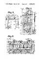
- FIG. 11is a fragmentary, vertical section of the dryer particularly showing heat lamp trays thereof and taken generally along line 11--11 in FIG. 6.
- FIG. 12is a fragmentary, vertical section of the dryer particularly showing a heat lamp tray and taken generally along line 12--12 in FIG. 11.
- FIG. 13is a fragmentary, front elevational view of a damper assembly in the dryer.
- FIG. 14is a schematic drawing of a power and control system of the dryer.
- the terms "upper”, “lower”, “front”, “back”, “right”, “left” and derivatives thereofrefer to the invention as oriented in FIG. 1. However, it is understood that the present invention may assume alternative orientations except where expressly specified to the contrary.
- the reference numeral 1generally designates a dryer for printed materials and the like.
- the dryer 1is operably positioned between a web offset rotary press 2 and a chiller 3.
- a web 4 of printed materialis received from the press 2 and passed through the dryer 1 to the chiller 3.
- ithas been found to be particularly effective in web offset printing operations and hence the preferred embodiment of the present invention is disclosed in such an environment.
- the dryer 1 of the present inventionmay also be employed for drying printed material in sheet form, ink or dye on fabric and various other coatings applied to or impregnated in various materials such as paper, paperboard stock, fabric, leather, metallic foil, plastic film and the like.
- dryingis likewise intended to encompass a variety of chemical and physical reactions which are induced by the dryer 1 of the present invention and generally involve the conversion of a liquid, especially one applied to a solid material, to a solid.
- the drying operation of the dryer 1is largely effected by the evaporation of the solvent in printing ink.
- setting, hardening, oxydizing, colloidal thickening, molecular redistribution and polarization processesmay also be effected or enhanced by the present invention on a wide variety of liquids applied to a wide variety of solids as aforementioned.
- the dryer 1generally comprises a frame structure 5, upper and lower heater panel assemblies 6, 7 an air handling system 8 and a power and control system 9.
- the frame structure 5 of the dryer 1includes a front and a back 11, 12; left and right sides 13, 14; and a top and a base 15, 16.
- Front and back lower longitudinal members 17, 18are positioned at the base 16 and the front and back 11, 12 respectively.
- a plurality of lower spacer members 19are attached to and extend between the front and back lower longitudinal members 17, 18.
- front and back 11, 12 opposed, upright pairs of front and back standardsare attached to and extend upwardly from respective front and back lower longitudinal members 17, 18.
- the standardscomprise front and back left standards 25, 26; front and back right standards 27, 28; front and back center standards 29, 30; and front and back intermediate standards 31, 32.
- Front and back upper longitudinal members 37, 38are attached to the upper ends of the front standards 25, 27, 29 and 31 and the back standards 26, 28, 30 and 32 at the frame structure top 15 and the front and back 11, 12 respectively.
- a blower support frame 39is attached to the upper longitudinal members 37, 38.
- Left and right lower members 41, 42are positioned at the frame structure base 16 and left and right sides 13, 14 respectively.
- Left side front and back uprights 43, 44extend upwardly from the left lower member 41 and are attached to the front and back left standards 25, 26 at the frame structure left side 13 and front and back 11, 12 respectively.
- Right side front and back uprights 45, 46extend upwardly from the right lower member 42 and are attached to the front and back right standards 27, 28 at the frame structure right side 14 and front and back 11, 12 respectively.
- H-shaped subframe 53which includes a cross-piece 54 and left and right uprights 55, 56 attached to respective front intermediate standards 31.
- a sheet metal lower front panel 63is attached to the lower part of frame structure front 11.
- a sheet metal control panel 64is mounted on the frame structure front 11 above the lower front panel 63.
- Left and right upper front sheet metal panels 65, 66are attached to the frame structure front 11 and extend between the front left and right standards 25, 27 and the front intermediate standards 31 respectively.
- a back panel 67is attached to the frame structure back 12.
- a pillow block-type bearing 72is mounted on the upper end of each linking drive shaft bearing post 71.
- the bearings 72are adapted to receive a linking drive shaft 73 which extends between the frame structure left and right sides 13, 14.
- the linking drive shaft 73is adapted for driving a piece of printing machinery, for example the chiller 3, on one side of the dryer 1 with another piece of printing machinery, for example the press 2, on the other side of the dryer 1.
- the aforementioned components of the frame structure 5may be connected by any suitable means including welding, bolting, riveting and the like or any combination thereof as appropriate.
- the frame structure 5may be placed on a floor surface 69 with its base 16 on any suitable support or foundation, movable or fixed.
- Each heater panel assembly 6, 7includes a respective guide frame 81 comprising a pair of longitudinal rails 82 interconnected by respective crosspieces 83 forming an H-shaped configuration. Attached to each longitudinal rail 82 approximately midway along its length is a respective roller assembly 84 with upper and lower sets of respective left, right and middle rollers 85, 86 and 87. The left and right rollers 85, 86 are spaced a distance slightly greater than the widths of the center standards 29, 30 and rotatably engage respective center standard side faces 88. Rotational axes of the left and right rollers 85, 86 extend from front to back with respect to the dryer 1.
- the middle rollers 87have rotational axes which extend from left to right with respect to the dryer 1 and rotatably engage respective center standard inner faces 89.
- the heater panel assemblies 6, 7are thus guided in their vertical movements within the frame structure 5 along the "Y" axis by the guide frames 81.
- Left-to-right alignment of the heater panel assemblies 6, 7 with respect to the "X" axisis maintained by the left and right rollers 85, 86 and front to back alignment with respect to the "Z" axis is maintained by the middle rollers 87.
- the heater panel assemblies 6, 7are maintained substantially level by providing upper and lower sets of rollers 85, 86 and 87 above and below each respective guide frame longitudinal rail 82.
- the upper and lower heater panel assemblies 6, 7are reciprocated within the frame structure 5 by an actuator comprising a double-acting pneumatic power cylinder 91 with an extensible and retractible rod 92.
- the cylinder 91is mounted on a cylinder mounting crosspiece 93 attached to and extending horizontally between the front and back center standards 29, 30.
- each cylinder standard 29, 30includes a plurality of vertically spaced receivers 94 for bolts which extend through the center standards 29, 30 and into the opposite ends of the cylinder mounting crosspiece 93.
- the vertical placement of the cylinder 91 beneath the lower heater panel assembly 7is determined by the corresponding opposite pair of receivers 94 chosen for mounting the crosspiece 93.
- the cylinder rod 92terminates at a clevis 95 which is connected to the guide frame crosspiece 83 of the lower heater panel assembly 7.
- the upper and lower heater panel assemblies 6, 7are operably interconnected by a system comprising four steel cables 100 each having opposite upper and lower ends 101, 102.
- Each longitudinal rail 42 of the upper heater panel assembly 6includes a pair of apertures (not shown) extending vertically therethrough for receiving respective cable upper ends 101.
- Each longitudinal rail 82 of the lower heater panel assembly 7includes a pair of angle-section cable clips 103 having apertures (also not shown) therethrough for receiving the respective lower ends 102 of the cables 100.
- the cable ends 101, 102are secured to respective guide frame longitudinal rails 82 by cable clamps 104 positioned below the longitudinal rails 82 of the upper heater panel assembly 6 and below the clips 103 attached to the longitudinal rails 82 of the lower heater panel assembly 7.
- the cables 100are trained over respective pulleys 105 attached to respective inner faces 106 of the intermediate standards 31, 32 adjacent their upper ends.
- the upper heater panel assemblies 6, 7are about 3 to 4 inches apart and the cables 100 assume a configuration as shown in FIG. 9 with their ends 101, 102 relatively close together.
- the heater panel assemblies 6, 7are moved to their respective open positions as shown in FIG. 10 by retracting the cylinder rod 92 whereby the lower heater panel assembly 7 is lowered within the frame structure 5.
- the cables 100are thus placed in tension and raise the upper heater panel assembly 6 to its open position.
- the geometry of each cable 100 and pulley 105 associated therewithis such that the vertical movements of the heater panel assemblies 6, 7 are directly porportional.
- both heater panel assemblies 6, 7are substantially the same distance from the paper web 4.
- the steel cables 100 and the power cylinder 91cooperate to provide a direct, simple and effective mechanical actuator means for opening and closing the heater panels 6, 7.
- the opening and closing movementscan be accomplished with a single power cylinder 91 and synchronization problems which might otherwise be encountered with more than one power cylinder are avoided.
- the cables 100 and pulleys 105cooperate with the guide roller assemblies 84 to maintain the heater panel assemblies 6, 7 in horizontal, parallel alignment and prevent them from tipping in any direction.
- the upper and lower heater panel assemblies 6, 7include heat lamp trays 111 connected to respective guide frames 81 by connecting straps 112 adjacent the ends of each guide frame 81.
- the straps 112have elongated slots 113 for receiving bolts 114 whereby they are adjustably attached to inside faces 115 of respective longitudinal rails 82.
- a respective connecting strap 112is attached to each end of each longitudinal rail 82 whereby the guide frames 81 are connected to the heat lamp trays 111 by four mounting straps 112 each.
- the heat lamp trays 111have rectangular configurations with fronts and backs 116, 117 respectively and left and right sides 118, 119 respectively.
- the heat lamp trays 111are bordered by front, back, left and right square tubular raceways 120, 121, 122 and 123 respectively. Raceway flanges 129 project inwardly from the front and back raceways 120, 121.
- the connecting straps 112are attached to the front and back raceways 120, 121.
- Each heat lamp tray 111includes a pair of rows of sockets 133 mounted in opposed relation on the front and back raceways 120, 121.
- the rows of sockets 133extend from left to right substantially the entire length of the front and back raceways 120, 121 in horizontally aligned and evenly spaced relation.
- Each socket 133is aligned front-to-back with a corresponding socket on the opposite raceway.
- a plurality of quartz tube heat lamps 134are placed in each heat lamp tray 111.
- the lamps 134include respective opposite ends 135 which interlock with the sockets 133.
- the sockets 133 and the lamp ends 135preferably comprise a non-electrically conductive insulating material, such as ceramic, capable of withstanding high temperatures.
- the lamps 134comprise nichrome elements enclosed in quartz tubes.
- the lamps 134are operated at relatively high temperatures (for example 1200 degrees to 1500 degrees Farhenheit) whereby short and medium wave infrared radiation with wavelengths in the respective ranges of 0.75 to 1.5 and 1.5 to 3.0 microns is produced.
- Short and medium wave infrared radiationis more intense and penetrates materials to be dried more deeply than long wave radiation with wavelengths in the range of 10 to 1000 microns.
- the quartz tube heat lamps 134 used in the present inventionoperating at high tempertures, have an estimated efficiency of 89% for conversion of input electricity into radiant heat for drying. Furthermore, a minimal amount of the short and medium wave radiant heat is lost to air absorption.
- the operating temperatures of the heat lamps 134 and the wavelengths of the radiant energy produced therebyare proportional to the level of input electricity. Lowering the level of input electricity results in lower lamp operating temperatures and proportionally longer wavelengths.
- the quartz tube heat lamps 134have been found to be particularly advantageous for drying ink on paper webs in high-speed rotary printing press operations.
- the infrared radiant energy produced therebypasses through air virtually undiminished and is almost completely absorbed after traveling a relatively short distance through most liquids and solids, for example printing ink on the paper web 4.
- the radiant energy produced by the lamps 134is thus almost entirely expended in evaporating the ink solvent, varnish and pigments and effecting the other physical and chemical reactions associated with and necessary for the drying process.
- the infrared radiant energy produced by the quartz tube heat lamps 134is also very effective for incinerating pollutants in the ink solvent, varnish and pigments whereby the exhaust from the dryer 1 has a relatively low level of pollutants which eliminates or at least reduces the amount of pollution control equipment required for its operation.
- the efficiency of the lamps 134is further increased by partially surrounding each lamp 134 with a polished aluminum reflector 136 for directing the infrared radiation toward the paper web 4.
- the reflectors 136have flat, horizontal bases 137, respective pairs of angled proximate legs 138 and respective pairs of vertical, distal legs 139.
- the lamps 134are positioned partly between the reflector distal legs 139.
- the reflectors 136open inwardly toward the paper web 4 between the respective distal legs 139.
- the reflector bases 137are fastened at their opposite ends to respective raceway flanges 129 by suitable mechanical fasteners 140.
- the reflectors 136are thus placed in juxtaposed relation in each respective heat lamp tray 111 and extend from front to back with respect to the frame structure 5.
- Upper and lower door panels 143, 144are attached to the upper and lower heater panel assemblies 6, 7 respectively by vertically adjustable mounting brackets 145.
- the door panels 143, 144are positioned in front of the heater panel assemblies 6, 7 and slidably engage the back of the H-shaped subframe 53 between the front intermediate standards 31.
- the door panels 143 and 144move vertically with the heater panel assemblies 6, 7 between open and closed positions. Therefore, when the heater panel assemblies 6, 7 are in their open positions, the heat lamp trays 111 and interior of the frame structure 5 are accessible through the open door panels 143, 144.
- the drying effect of the heat from the heat lamps 134is supplemented and enhanced by providing an air handling system 8 for mechanically induced forced air and exhaust.
- the air handling system 8generally comprises a drying air subsystem 151, a cooling air subsystem 152 and an exhaust subsystem 153.
- the drying air subsystem 151includes a blower 158 with a fan 159 operably connected to a blower motor 160 mounted on a motor stand 161 attached to and positioned on top of the blower base frame 39. Drying air is drawn by the blower 158 through a drying air filter 162 in an intake 163.
- the drying air blower 158communicates forced air with a drying air duct network 164.
- the drying air duct network 164includes a sheet metal, 90 degree first drying air elbow 165 communicating forced air from the drying air fan 159 to the frame structure top 15 whereat the drying airstream is split into upper and lower portions.
- the upper portion of the drying airstreamis ducted through a 90 degree second drying air elbow 166 to an upper drying air manifold 167 which extends substantially the length of the frame structure 5 along the back 12 thereof.
- the lower portion of the drying airstreamis directed downwardly through third and fourth drying air elbows 173, 174 to a drying air vertical run 176 positioned alongside the back left standard 26 at the frame structure back 12.
- the vertical run 176terminates at its lower end at a 90 degree fifth drying air elbow 175 communicating with a lower drying air manifold 177.
- a plurality of drying air sleeves 168extend forwardly from the upper and lower drying air manifolds 167, 177 and are positioned in longitudinally spaced relation.
- Flexible drying air hoses 169are each connected to a respective drying air sleeve 168 and terminate at drying air nozzles 170 attached to the heat lamp trays 111 of the upper and lower heater panel assemblies 6, 7.
- Forced air from the drying air subsystem 151is directed through the nozzles 170 to the paper web 4 to facilitate drying the ink solvent thereon and also to provide an airstream across the web 4 and within the dryer 1 for removal of particulates, evaporated solvent, varnish, pigments and the like.
- a damper assembly 185is provided in the drying air subsystem 151 and includes a damper plate 186 pivotally mounted within the first drying air elbow 165.
- a damper actuator lever 187is connected at one end to the damper plate 186 and has a roller 188 mounted at its other end. As shown in FIG. 13, the damper actuator lever is angled whereby a proximate leg 189 and a distal leg 190 are formed and are angularly disposed with respect to each other.
- the actuator lever roller 188rollably engages a roller track 191 extending forwardly from the inside face 115 of the guide frame longitudinal rail 92 of the upper heater panel assembly 6 in proximity to its left end.
- the damper assembly 185is in its open position when the upper heater panel assembly is in its lowered, closed position whereby forced air is blown through upper portions of the drying air duct network 164 to the web 4 for facilitating the drying process. With the damper assembly 185 in its open position, the actuator lever roller 188 is at its left-most and lowest position as shown in FIG. 13.
- the cooling air subsystem 152includes upper and lower cooling air blowers 195, 196 with respective cooling air blower fans 197 operably connected to respective cooling air blower motors 198.
- the upper cooling air blower 195is mounted above the frame structure top 15 and its fan 197 is operably connected to a cooling air duct network 199 at an upper cooling air junction box 200 positioned beneath the frame structure top 15 adjacent the frame structure right side 14.
- the cooling air blower fan 197 of the lower cooling air blower 196is connected to the cooling air duct network 199 at a 45 degree first cooling air elbow 201 mounted on the back side of the frame structure back panel 67 in proximity to the frame structure right side 14 and base 16.
- the first cooling air elbow 201communicates with a lower cooling air junction box 202 positioned on the front side of the back panel 67.
- Each upper and lower cooling air junction box 200, 202has a pair of cooling air sleeves 203 extending therefrom and communicating with respective flexible cooling air hoses 204.
- the cooling air hoses 204at their opposite ends receive respective cooling air sleeves 203 located at the corners of the heat lamp trays 111 where the front and back raceways 120, 121 intersect the right raceway 122.
- the cooling air blowers 195force air through the cooling air duct network 199 to the front and back lamp tray raceways 120, 121.
- the cooling airis blown through the raceways 120, 121 to remove excess heat therefrom.
- the cooling airis exhausted through raceway louvres 131 at the left ends of the front and back raceways 120, 121.
- Cooling means for the raceways 120, 121is provided because heat generated by the elecrical current in heat lamp wires 256 and the heat lamps 134 might create a fire hazard or otherwise damage the dryer 1.
- the exhaust subsystem 153includes upper and lower exhaust blowers 215, 216 mounted on the blower base frame 39 and drawing exhaust from the dryer 1 through an exhaust duct network 220.
- Each exhaust blower 215, 216includes a respective exhaust blower fan 217 operably connected to a respective exhaust blower motor 218 mounted on a respective exhaust motor stand 219.
- the blower motor stands 219are attached to the blower base frame 39.
- the fan 217 of the upper exhaust blower 215communicates with a first exhaust elbow 221 which extends through the frame structure top 15 and terminates at a "T" connection 222 with an upper exhaust manifold 223 extending from left-to-right slightly below the frame structure top 15.
- the upper exhaust manifold 223is suspended from the upper spacers 49 of the frame structure 5 by hangers 224.
- the lower exhaust blower 216receives air from a second exhaust elbow 226 at the upper end of an exhaust run 227.
- a 90 degree third exhaust elbow 228extends through the back panel 67 of the frame structure 5.
- the third exhaust elbow 28draws air from a lower exhaust manifold 229 including a front-to-back leg 230 and a left-to-right leg 231.
- the exhaust duct network 220includes a plurality of exhaust sleeves 236 extending rearwardly from the upper exhaust manifold 223 and the left-to-right leg 231 of the lower exhaust manifold 229.
- the exhaust sleevesare received in ends of flexible exhaust hoses 237 which receive exhaust hoods 238 in their opposite ends.
- Each exhaust hoodis mounted on a respective heat lamp tray 111 on the respective front and back raceways 120, 121.
- the exhaust hoods 238are provided over approximately the right-most two-thirds of the heat lamp trays 111 and each covers a plurality of heat lamps 134.
- the exhaust hoods 238are not provided on the remaining left-most portions of the heat lamp trays 111 because the web 4 is relatively cool there and emits most of its evaporated solvent, varnish and pigment further to the right after being heated. Furthermore, the rapidly moving paper web 4 tends to impart inertia to the exhaust whereby it tends to be carried along with the moving paper web to the right where it are drawn off by the exhaust hoods 238.
- the exhaustis drawn from the moving web 4 and its surrounding vicinity and thence through the exhaust duct network 220 to the exhaust blower fans 217 from which it may be exhausted to, for example, a roof vent or pollution control equipment.
- the radiant energy from the quartz tube heat lamps 134 and the forced air from the air handling system 8cooperate to reduce the level of pollutants both within the dryer 1 and in its exhaust.
- the radiant energytends to incinerate much of the evaporated solvent, varnish and pigment or at least convert it to a less harmful condition within the dryer 1.
- the air flow established by the air handling system 8effectively removes most of the remaining solvents, varnishes and pigments and the by-products of the radiant thermal incineration. Therefore, only very small amounts of the aforementioned substances accumulate within the dryer 1 and a relatively clean drying operation is effected.
- the dryer 1 of the present inventionoperates on electrical power.
- the power and control system 9 thereforincludes an upper electrical enclosure 245 with power relays and starters for the motors 160, 198 and 218.
- the drying air blower motor 160 and the exhaust blower motors 218require 220 volt, single phase, 25 ampere current in the preferred embodiment.
- the cooling air blower motors 198operate on 110 volt service.
- the upper electrical enclosure 245is mounted on the back panel 67 adjacent the left side 13 of the frame structure 5.
- a lower electrical enclosure 246is mounted on the frame structure back panel 67 directly below the upper electrical enclosure 245.
- the lower electrical enclosure 246houses a power controller 250 for the heat lamps 134.
- the heat lamps 134are provided with 480 volt, three phase, 150 ampere service.
- electrical service for the heat lamps 134 in the range of 220 to 575 voltsis contemplated.
- the power controller 250is operably connected to a temperature controller 251 which is also housed within the lower electrical enclosure 246.
- a thermal-type infrared detector 252is mounted on the frame structure right side 14 adjacent the path of the web 4 where it exits the dryer 1 and is operably connected to the temperature controller 251. The resistance of the infrared detector 252 is proportional to the heat of the paper web 4.
- the temperature controller 251generates a milliampere signal with a value determined by the resistance of the infrared dectector 252 and a preset temperature range for the web 4 which is programmed into the temperature controller 251.
- the signal generated by the temperature controller 251is transmitted to the power controller 250.
- the temperature controller 251includes a digital display for indicating the temperature of the web 4.
- the power controller 250 and the temperature controller 251cooperate with the infrared detector 252 to automatically and constantly adjust the level of current to the heat lamps 134 and thereby maintain the temperature of the web 4 within relatively close tolerances.
- the web 4is thus exposed to sufficient heat for effective drying of the ink thereon without excessive heat exposure which could scorch or even ignite the web 4.
- a potentiometercould be provided for manually controlling the current to the heat lamps 134 and the temperature of the web 4.
- a vertical wiring trough 255protrudes from the frame structure back panel 67 to the right of the electrical enclosures 245, 246.
- Heat lamp wires 255extend from the power controller 250, through the wiring trough 255, into the interior of the frame structure 5 and through respective heat lamp tray raceways 120, 121 and 122 to respective electrodes (not shown) at each socket 133. Between the lower electrical enclosure 346 and the heat lamp trays 111, the heat lamp wires 255 are enclosed within flexible electrical conduit 257. Within the front and back raceways 120, 121 the heat lamp wires 255 are cooled by the cooling air subsystem 152.
- Compressed air from an air compressor 260is communicated to a two-way solenoid-actuated air valve 261 mounted on the wiring trough 255 by a compressor air line 262.
- Upper and lower air lines 263, 264communicate pressurized air from the air valve 261 to respective upper and lower ends of the cylinder 91.
- the air valve 261operably connects the compressor 260 and the upper air line 263 whereby pressurized air is communicated to the upper end of the cylinder 91.
- the rod 92is thus retracted and the heat lamp trays 111 are open.
- the power cylinder 91 and the air valve 261cooperate to automatically open the heater panel assemblies 6, 7 in the event of a power outage or other malfunction.
- the heat lamps 134extinguish but retain substantial amounts of residual heat for several seconds in spite of their relatively low thermal masses. If the press 2 and other printing equipment are also effected, the web 4 may stop within the dryer 1 and thus be susceptible to scorching or ignition if the heater panels 6, 7 are not immediately removed from the web 4.
- the pneumatic system of the dryer 1is designed to automatically open the heater panels 6, 7 in the event of a power outage.
- the air valve 261is immediately biased by a return spring (not shown) to its first position when its solenoid is deactivated. Pressurized air is thus communicated to the upper end of the cylinder 91, the rod 92 retracted and the heater panel assemblies 6, 7 vertically moved to their respective open positions a sufficiently safe distance from the web 4.
- the entire power and control system 9 of the dryer 1is actuated by a switch 265 on the first impression cylinder (not shown) of the press 2.
- the microswitchcloses and relays within the electrical enclosures 245 and 246 actuate the blower motors 160, 198 and 218 respectively; the heat lamps 134; and the solenoid of the air valve 261.
- the dryer 1is thus operational and functions to dry the paper web 4 passing therethrough.
- the switch 265opens and the dryer 1 is shut down with its heat lamp trays 111 open.
Landscapes
- Engineering & Computer Science (AREA)
- Mechanical Engineering (AREA)
- General Engineering & Computer Science (AREA)
- Life Sciences & Earth Sciences (AREA)
- Microbiology (AREA)
- Textile Engineering (AREA)
- Drying Of Solid Materials (AREA)
Abstract
Description
1. Field of the Invention
This invention relates generally to dryers for printed materials and the like, and in particular to a dryer for printed webs utilizing infrared radiant heat and forced air.
2. Description of the Prior Art
In the printing field, dryers are often employed to shorten the drying time of inks and dyes applied to various materials such as paper and paperboard stocks, metallic foils, plastic films and cloth. Such materials may be printed in the form of either individual sheets or in continuous webs.
Printing inks and dyes generally contain solvents, varnishes and pigments which evaporate after sufficient exposure to ambient atmospheric conditions. However, in printing operations it is frequently desirable to hasten the drying process so that the printed materials may be stacked, rewound, cut, folded or otherwise further processed without smearing the ink or dye thereon.
One method of reducing the drying time involves the application of anti-offset powder to the freshly printed materials. The powder absorbs the solvents in the ink or dye to prevent smearing when the materials are further processed. However, the powder and the equipment for its application increase the printing costs. Also, drying powder tends to disperse widely around the area of the printing operation, interferes with equipment, and must be periodically cleaned up whereby the printer incurs additional maintenance costs by its use.
A variety of different dryers and ovens have been devised for applying heat to freshly-printed material. For example, tunnel ovens have heretofore been provided for transferring heat to webs of printed material. In tunnel ovens, the heat exchange occurs primarily by convection. However, tunnel ovens tend to be relatively large and are therefore unsuitable where floor space is limited. Also, they are relatively inefficient because much of the heat generated thereby is absorbed by the atmosphere and the surrounding structure instead of the printing material and the ink thereon.
Radiant heaters are generally more efficient in drying operations than convective heaters because radiant energy is transmitted through the atmosphere with very little loss and is absorbed by liquids and solids. Therefore, relatively little radiant energy is wasted through absorption into the atmosphere. Furthermore, radiant energy may be directed with reflectors and the like so that most of it is received and absorbed by the printed material in a dryer.
Yet another advantage of using radiant energy for drying printed materials relates to the control and elimination of pollutants found in the evaporated solvents, varnishes and pigments of inks and dyes. Prior art forced air-type convection dryers which include burners for natural gas, propane or fuel oil generally emit substantial amounts of pollutants in the form of evaporated solvents, varnishes and pigments. Accordingly, air pollution control equipment such as afterburners for thermal and catalytic incineration and electrostatic precipitators for particulates must be provided in order to satisfy applicable environmental protection laws and regulations and to meet local code requirements. However, a large portion of the aforementioned pollutants from a drying operation may be incinerated within the dryer or otherwise converted to a less harmful condition by radiant energy. Therefore, dryers which employ radiant energy require less pollution control equipment than convection-type dryers of comparable capacity or else require no pollution control equipment.
In particular, short and medium wave infrared energy with wavelengths of 0.75 to 1.5 and 1.5 to 3.0 microns respectively is effective for drying and incinerating the solvents, varnishes and pigments in printing inks and dyes. The wavelength of infrared radiation is determined by the temperature of the emitting body with higher temperatures producing shorter wavelengths. Short and medium wave infrared radiation penetrates deeper and is more intense than long wave infrared radiation. Although all bodies not at absolute zero emit infrared radiation, quartz tube heat lamps offer several advantages. First of all, they are relatively efficient in converting input electricity into radiant heat for drying ink and dye solvents, varnishes and pigments with minimal heat loss through absorption into the ambient atmosphere. For example, quartz tube heat lamps are available with an operational efficiency of approximately 89%.
Secondly, quartz tube heat lamps tend to have a relatively low thermal mass and thus can be switched on and off relatively rapidly. In drying wet materials, this is particularly important as a safety feature because in the event of a web stoppage, it is important to remove the heat therefrom immediately to avoid igniting the stopped web.
Furthermore, the output of quartz tube heat lamps can be relatively precisely controlled by varying the electrical input to their filaments. Thus, a web of printed material may be run at a constant speed through a dryer or oven and the precise amount of radiant heat required for proper drying can be applied by such control means. Drying systems lacking such precise control means are not only wasteful of energy, but may actually harm the printed product. For example, if the ink is not sufficiently dry, it is more susceptible to smearing. On the other hand, excessive heat can weaken the cellulose in the printed material, break the web or ignite it.
To take advantage of the aforementioned characteristics of infrared heating, many modern printing systems employ inks which are especially formulated to dry quickly when exposed to infrared radiant energy.
The drying of ink and dye and solvents on printed materials may also be hastened by directing a drying fluid such as air, oxygen or ozone over the printed material. Without such a fluid flow, heat-induced drying is less efficient because the evaporated solvent tends to collect in a layer over the printed material. The evaporated solvent insulates the printed material from radiant and convection heat and inhibits further solvent evaporation. Although movement of a web of printed material accounts for a certain amount of air circulation, a system for forcing drying fluid through the dryer in conjunction with a heat source is preferred.
Quartz tube heat lamps and forced drying fluid systems are known in the printing art as exemplified by the Hanson U.S. Pat. No. 2,065,070; the Early et al. U.S. Pat. No. 3,159,464 and the Visser U.S. Pat. No. 3,122,999. However, a persistent problem not effectively solved by the prior art relates to the immediate removal of the radiant heat from the web in the event of a stoppage for any reason. If the heat is not removed quickly enough, the web may be scorched, ignited and broken. Although quartz tube heat lamps have relatively low thermal masses as aforementioned, the high operating temperatures required to produce short wave infrared radiation increase the risk of web damage if the heat lamps are not immediately withdrawn a safe distance from the stopped web. Also, many prior art dryers were ineffective at reducing the level of pollutants in their exhausts.
Heretofore quartz tube heat lamps and a forced air system have not been available in a dryer designed to reduce the exhaust pollutant level and to automatically remove the heat source from the printed material as required to safely operate the heat lamps in the short wave infrared range.
In the practice of the present invention, a dryer for printed material and the like is provided which includes a frame structure having upper and lower heater panel assemblies with quartz tube heat lamps. The heater panel assemblies are vertically movable between open and closed positions with respect to a web of printed material by actuator means comprising a pneumatic cylinder. An air handling system includes a drying air subsystem for directing a flow of drying air across the web, a cooling air subsystem for cooling heat lamp wires and an exhaust subsystem for removing the drying air from the dryer.
The principal objects of the present invention are: to provide a dryer for printed materials and the like; to provide such a dryer which applies infrared radiant energy to printed material and the like; to provide such a dryer with quartz tube heat lamps; to provide such a dryer which reduces the level of pollutants in its exhaust; to provide such a dryer which reduces the exhaust pollutant level by incinerating pollutants with radiant energy within the dryer; to provide such a dryer with means for automatically and quickly removing the heat from a web of printed material in the event of a web stoppage; to provide such a dryer with an air handling subsystem for applying a flow of drying air to the printed material; to provide such a dryer with a cooling air subsystem for cooling heat lamp wires; to provide such a dryer with an exhaust air subsystem for removing evaporated solvent-laden drying air therefrom; to provide such a dryer with a photoelectric detector for determining the temperature of a web of printed material; to provide such a dryer which is particularly adapted for drying a web of printed material; to provide such a dryer which is capable of drying a web of printed material moving at a relatively high speed therethrough; to provide such a dryer which is relatively clean in operation; to provide such a dryer which efficiently transfers energy to the printed material; and to provide such a dryer which is economical to manufacture, efficient in operation, capable of a long operating life and particularly well adapted for the proposed usage thereof.
Other objects and advantages of this invention will become apparent from the following description taken in conjunction with the accompanying drawings wherein are set forth, by way of illustration and example, certain embodiments of this invention.
The drawings constitute a part of this specification and include exemplary embodiments of the present invention and illustrate various objects and features thereof.
FIG. 1 is a front elevational view of a dryer embodying the present invention shown between a rotary printing press and a chiller.
FIG. 2 is a front elevational view of the dryer with portions broken away to reveal the internal construction thereof.
FIG. 3 is a rear elevational view of the dryer.
FIG. 4 is an elevational view of the right side of the dryer.
FIG. 5 is a horizontal section of the dryer taken generally alongline 5--5 in FIG. 2.
FIG. 6 is a horizontal section of the dryer taken generally alongline 6--6 in FIG. 2.
FIG. 7 is a horizontal section of the dryer taken generally alongline 7--7 in FIG. 2.
FIG. 8 is a horizontal section of the dryer taken generally alongline 8--8 in FIG. 2.
FIG. 9 is a vertical section of the dryer taken generally alongline 9--9 in FIG. 2.
FIG. 10 is a fragmentary, vertical section of the dryer taken generally alongline 10--10 in FIG. 2.
FIG. 11 is a fragmentary, vertical section of the dryer particularly showing heat lamp trays thereof and taken generally alongline 11--11 in FIG. 6.
FIG. 12 is a fragmentary, vertical section of the dryer particularly showing a heat lamp tray and taken generally alongline 12--12 in FIG. 11.
FIG. 13 is a fragmentary, front elevational view of a damper assembly in the dryer.
FIG. 14 is a schematic drawing of a power and control system of the dryer.
As required, detailed embodiments of the present invention are disclosed herein, however, it is to be understood that the disclosed embodiments are merely exemplary of the invention which may be embodied in various forms. Therefore, specific structural and functional details disclosed herein are not to be interpreted as limiting, but merely as a basis for the claims and as a representative basis for teaching one skilled in the art to variously employ the present invention in virtually any appropriately detailed structure.
As used herein, the terms "upper", "lower", "front", "back", "right", "left" and derivatives thereof refer to the invention as oriented in FIG. 1. However, it is understood that the present invention may assume alternative orientations except where expressly specified to the contrary.
Referring to the drawings in more detail, the reference numeral 1 generally designates a dryer for printed materials and the like. In the preferred embodiment of the present invention, the dryer 1 is operably positioned between a web offsetrotary press 2 and a chiller 3. Aweb 4 of printed material is received from thepress 2 and passed through the dryer 1 to the chiller 3. Without limitation on the generality of useful applications of the dryer 1 comprising the present invention, it has been found to be particularly effective in web offset printing operations and hence the preferred embodiment of the present invention is disclosed in such an environment.
The dryer 1 of the present invention may also be employed for drying printed material in sheet form, ink or dye on fabric and various other coatings applied to or impregnated in various materials such as paper, paperboard stock, fabric, leather, metallic foil, plastic film and the like.
The term "drying" is likewise intended to encompass a variety of chemical and physical reactions which are induced by the dryer 1 of the present invention and generally involve the conversion of a liquid, especially one applied to a solid material, to a solid. The drying operation of the dryer 1 is largely effected by the evaporation of the solvent in printing ink. However, setting, hardening, oxydizing, colloidal thickening, molecular redistribution and polarization processes may also be effected or enhanced by the present invention on a wide variety of liquids applied to a wide variety of solids as aforementioned.
The dryer 1 generally comprises aframe structure 5, upper and lowerheater panel assemblies air handling system 8 and a power andcontrol system 9.
Theframe structure 5 of the dryer 1 includes a front and a back 11, 12; left andright sides base longitudinal members base 16 and the front and back 11, 12 respectively. A plurality oflower spacer members 19 are attached to and extend between the front and back lowerlongitudinal members
At the frame structure front and back 11, 12 opposed, upright pairs of front and back standards are attached to and extend upwardly from respective front and back lowerlongitudinal members standards 25, 26; front and backright standards back center standards 29, 30; and front and backintermediate standards
Front and back upperlongitudinal members front standards back standards frame structure top 15 and the front and back 11, 12 respectively. Ablower support frame 39 is attached to the upperlongitudinal members
Left and rightlower members frame structure base 16 and left andright sides lower member 41 and are attached to the front and back leftstandards 25, 26 at the frame structure leftside 13 and front and back 11, 12 respectively. Right side front and back uprights 45, 46 extend upwardly from the rightlower member 42 and are attached to the front and backright standards right side 14 and front and back 11, 12 respectively.
Left and rightupper members left side uprights 43, 44 and the right side uprights 45, 46 respectively.Upper spacer members 49 are attached to and extend between the upperlongitudinal members frame structure front 11 an H-shapedsubframe 53 is provided which includes across-piece 54 and left andright uprights intermediate standards 31.
A sheet metal lowerfront panel 63 is attached to the lower part offrame structure front 11. A sheetmetal control panel 64 is mounted on theframe structure front 11 above the lowerfront panel 63. Left and right upper frontsheet metal panels frame structure front 11 and extend between the front left andright standards intermediate standards 31 respectively. Aback panel 67 is attached to the frame structure back 12.
Attached to thelower spacer members 19 and extending upwardly therefrom are respective bearing posts 71. A pillow block-type bearing 72 is mounted on the upper end of each linking driveshaft bearing post 71. Thebearings 72 are adapted to receive a linkingdrive shaft 73 which extends between the frame structure left andright sides drive shaft 73 is adapted for driving a piece of printing machinery, for example the chiller 3, on one side of the dryer 1 with another piece of printing machinery, for example thepress 2, on the other side of the dryer 1.
The aforementioned components of theframe structure 5 may be connected by any suitable means including welding, bolting, riveting and the like or any combination thereof as appropriate. Theframe structure 5 may be placed on afloor surface 69 with itsbase 16 on any suitable support or foundation, movable or fixed.
Eachheater panel assembly respective guide frame 81 comprising a pair oflongitudinal rails 82 interconnected byrespective crosspieces 83 forming an H-shaped configuration. Attached to eachlongitudinal rail 82 approximately midway along its length is arespective roller assembly 84 with upper and lower sets of respective left, right andmiddle rollers right rollers center standards 29, 30 and rotatably engage respective center standard side faces 88. Rotational axes of the left andright rollers middle rollers 87 have rotational axes which extend from left to right with respect to the dryer 1 and rotatably engage respective center standard inner faces 89. Theheater panel assemblies frame structure 5 along the "Y" axis by the guide frames 81. Left-to-right alignment of theheater panel assemblies right rollers middle rollers 87. Furthermore, theheater panel assemblies rollers longitudinal rail 82.
The upper and lowerheater panel assemblies frame structure 5 by an actuator comprising a double-actingpneumatic power cylinder 91 with an extensible andretractible rod 92. Thecylinder 91 is mounted on acylinder mounting crosspiece 93 attached to and extending horizontally between the front andback center standards 29, 30. As shown in FIG. 2, each cylinder standard 29, 30 includes a plurality of vertically spacedreceivers 94 for bolts which extend through thecenter standards 29, 30 and into the opposite ends of thecylinder mounting crosspiece 93. The vertical placement of thecylinder 91 beneath the lowerheater panel assembly 7 is determined by the corresponding opposite pair ofreceivers 94 chosen for mounting thecrosspiece 93. Thecylinder rod 92 terminates at aclevis 95 which is connected to theguide frame crosspiece 83 of the lowerheater panel assembly 7.
The upper and lowerheater panel assemblies steel cables 100 each having opposite upper and lower ends 101, 102. Eachlongitudinal rail 42 of the upperheater panel assembly 6 includes a pair of apertures (not shown) extending vertically therethrough for receiving respective cable upper ends 101. Eachlongitudinal rail 82 of the lowerheater panel assembly 7 includes a pair of angle-section cable clips 103 having apertures (also not shown) therethrough for receiving the respective lower ends 102 of thecables 100. The cable ends 101, 102 are secured to respective guide framelongitudinal rails 82 by cable clamps 104 positioned below thelongitudinal rails 82 of the upperheater panel assembly 6 and below theclips 103 attached to thelongitudinal rails 82 of the lowerheater panel assembly 7.
Thecables 100 are trained overrespective pulleys 105 attached to respective inner faces 106 of theintermediate standards heater panel assemblies heater panel assemblies cables 100 assume a configuration as shown in FIG. 9 with theirends heater panel assemblies cylinder rod 92 whereby the lowerheater panel assembly 7 is lowered within theframe structure 5. Thecables 100 are thus placed in tension and raise the upperheater panel assembly 6 to its open position. The geometry of eachcable 100 andpulley 105 associated therewith is such that the vertical movements of theheater panel assemblies heater panel assemblies paper web 4.
Thesteel cables 100 and thepower cylinder 91 cooperate to provide a direct, simple and effective mechanical actuator means for opening and closing theheater panels panels cables 100 andpulleys 105, the opening and closing movements can be accomplished with asingle power cylinder 91 and synchronization problems which might otherwise be encountered with more than one power cylinder are avoided. Furthermore, thecables 100 andpulleys 105 cooperate with theguide roller assemblies 84 to maintain theheater panel assemblies
The upper and lowerheater panel assemblies straps 112 adjacent the ends of eachguide frame 81. Thestraps 112 have elongatedslots 113 for receivingbolts 114 whereby they are adjustably attached to inside faces 115 of respectivelongitudinal rails 82. A respective connectingstrap 112 is attached to each end of eachlongitudinal rail 82 whereby the guide frames 81 are connected to the heat lamp trays 111 by four mountingstraps 112 each. The heat lamp trays 111 have rectangular configurations with fronts and backs 116, 117 respectively and left andright sides 118, 119 respectively. The heat lamp trays 111 are bordered by front, back, left and right squaretubular raceways Raceway flanges 129 project inwardly from the front andback raceways straps 112 are attached to the front andback raceways
Each heat lamp tray 111 includes a pair of rows ofsockets 133 mounted in opposed relation on the front andback raceways sockets 133 extend from left to right substantially the entire length of the front andback raceways socket 133 is aligned front-to-back with a corresponding socket on the opposite raceway.
A plurality of quartztube heat lamps 134 are placed in each heat lamp tray 111. Thelamps 134 include respective opposite ends 135 which interlock with thesockets 133. Thesockets 133 and the lamp ends 135 preferably comprise a non-electrically conductive insulating material, such as ceramic, capable of withstanding high temperatures.
Thelamps 134 comprise nichrome elements enclosed in quartz tubes. Preferably, thelamps 134 are operated at relatively high temperatures (for example 1200 degrees to 1500 degrees Farhenheit) whereby short and medium wave infrared radiation with wavelengths in the respective ranges of 0.75 to 1.5 and 1.5 to 3.0 microns is produced. Short and medium wave infrared radiation is more intense and penetrates materials to be dried more deeply than long wave radiation with wavelengths in the range of 10 to 1000 microns.
The quartztube heat lamps 134 used in the present invention, operating at high tempertures, have an estimated efficiency of 89% for conversion of input electricity into radiant heat for drying. Furthermore, a minimal amount of the short and medium wave radiant heat is lost to air absorption. The operating temperatures of theheat lamps 134 and the wavelengths of the radiant energy produced thereby are proportional to the level of input electricity. Lowering the level of input electricity results in lower lamp operating temperatures and proportionally longer wavelengths.
The quartztube heat lamps 134 have been found to be particularly advantageous for drying ink on paper webs in high-speed rotary printing press operations. The infrared radiant energy produced thereby passes through air virtually undiminished and is almost completely absorbed after traveling a relatively short distance through most liquids and solids, for example printing ink on thepaper web 4. The radiant energy produced by thelamps 134 is thus almost entirely expended in evaporating the ink solvent, varnish and pigments and effecting the other physical and chemical reactions associated with and necessary for the drying process. The infrared radiant energy produced by the quartztube heat lamps 134 is also very effective for incinerating pollutants in the ink solvent, varnish and pigments whereby the exhaust from the dryer 1 has a relatively low level of pollutants which eliminates or at least reduces the amount of pollution control equipment required for its operation.
The efficiency of thelamps 134 is further increased by partially surrounding eachlamp 134 with apolished aluminum reflector 136 for directing the infrared radiation toward thepaper web 4. Thereflectors 136 have flat,horizontal bases 137, respective pairs of angledproximate legs 138 and respective pairs of vertical,distal legs 139. Thelamps 134 are positioned partly between the reflectordistal legs 139. Thereflectors 136 open inwardly toward thepaper web 4 between the respectivedistal legs 139. The reflector bases 137 are fastened at their opposite ends torespective raceway flanges 129 by suitablemechanical fasteners 140. Thereflectors 136 are thus placed in juxtaposed relation in each respective heat lamp tray 111 and extend from front to back with respect to theframe structure 5.
Upper andlower door panels heater panel assemblies brackets 145. Thedoor panels heater panel assemblies subframe 53 between the frontintermediate standards 31. Thedoor panels heater panel assemblies heater panel assemblies frame structure 5 are accessible through theopen door panels
The drying effect of the heat from theheat lamps 134 is supplemented and enhanced by providing anair handling system 8 for mechanically induced forced air and exhaust. Theair handling system 8 generally comprises a dryingair subsystem 151, a coolingair subsystem 152 and anexhaust subsystem 153.
The dryingair subsystem 151 includes ablower 158 with afan 159 operably connected to ablower motor 160 mounted on amotor stand 161 attached to and positioned on top of theblower base frame 39. Drying air is drawn by theblower 158 through a dryingair filter 162 in anintake 163.
The dryingair blower 158 communicates forced air with a dryingair duct network 164. The dryingair duct network 164 includes a sheet metal, 90 degree first dryingair elbow 165 communicating forced air from the dryingair fan 159 to theframe structure top 15 whereat the drying airstream is split into upper and lower portions. The upper portion of the drying airstream is ducted through a 90 degree second drying air elbow 166 to an upperdrying air manifold 167 which extends substantially the length of theframe structure 5 along theback 12 thereof.
The lower portion of the drying airstream is directed downwardly through third and fourthdrying air elbows vertical run 176 positioned alongside the back left standard 26 at the frame structure back 12. Thevertical run 176 terminates at its lower end at a 90 degree fifth dryingair elbow 175 communicating with a lowerdrying air manifold 177. A plurality of dryingair sleeves 168 extend forwardly from the upper and lowerdrying air manifolds drying air hoses 169 are each connected to a respectivedrying air sleeve 168 and terminate at dryingair nozzles 170 attached to the heat lamp trays 111 of the upper and lowerheater panel assemblies air subsystem 151 is directed through thenozzles 170 to thepaper web 4 to facilitate drying the ink solvent thereon and also to provide an airstream across theweb 4 and within the dryer 1 for removal of particulates, evaporated solvent, varnish, pigments and the like.
Adamper assembly 185 is provided in the dryingair subsystem 151 and includes adamper plate 186 pivotally mounted within the firstdrying air elbow 165. A damper actuator lever 187 is connected at one end to thedamper plate 186 and has aroller 188 mounted at its other end. As shown in FIG. 13, the damper actuator lever is angled whereby a proximate leg 189 and adistal leg 190 are formed and are angularly disposed with respect to each other.
Theactuator lever roller 188 rollably engages aroller track 191 extending forwardly from theinside face 115 of the guide framelongitudinal rail 92 of the upperheater panel assembly 6 in proximity to its left end. Thedamper assembly 185 is in its open position when the upper heater panel assembly is in its lowered, closed position whereby forced air is blown through upper portions of the dryingair duct network 164 to theweb 4 for facilitating the drying process. With thedamper assembly 185 in its open position, theactuator lever roller 188 is at its left-most and lowest position as shown in FIG. 13.
When theheater panel assemblies roller 188 rolls along itstrack 191 to its right-most position as shown in phantom in FIG. 13 whereby thedamper plate 186 is pivoted to its closed position for blocking air flow through the firstdrying air elbow 165 and thus to all of the upper portions of the dryingair duct network 164. With thedamper assembly 185 thus closed, all of the drying airstream is diverted to the lower portions of the dryingair duct network 164 and blown upwardly through the lowerdrying air nozzles 170 against the underside of theweb 4. Theweb 4 is thus supported on a cushion of air approximately midway between the openheater panel assemblies heater panel assembly 7 is positioned in spaced relation some distance below theweb 4. Supporting theweb 4 in this fashion prevents it from sagging and coming into contact with hot portions of the lowerheater panel assembly 7 which could conceivably set it afire due to the residual heat therein even though theheat lamps 134 are extinguished.
The coolingair subsystem 152 includes upper and lowercooling air blowers 195, 196 with respective coolingair blower fans 197 operably connected to respective coolingair blower motors 198. The uppercooling air blower 195 is mounted above theframe structure top 15 and itsfan 197 is operably connected to a coolingair duct network 199 at an upper coolingair junction box 200 positioned beneath theframe structure top 15 adjacent the frame structureright side 14. The coolingair blower fan 197 of the lower cooling air blower 196 is connected to the coolingair duct network 199 at a 45 degree first coolingair elbow 201 mounted on the back side of the frame structure backpanel 67 in proximity to the frame structureright side 14 andbase 16. The firstcooling air elbow 201 communicates with a lower coolingair junction box 202 positioned on the front side of theback panel 67.
Each upper and lower coolingair junction box air sleeves 203 extending therefrom and communicating with respective flexiblecooling air hoses 204. The coolingair hoses 204 at their opposite ends receive respectivecooling air sleeves 203 located at the corners of the heat lamp trays 111 where the front andback raceways right raceway 122.
In operation, the coolingair blowers 195 force air through the coolingair duct network 199 to the front and backlamp tray raceways raceways raceway louvres 131 at the left ends of the front andback raceways raceways heat lamp wires 256 and theheat lamps 134 might create a fire hazard or otherwise damage the dryer 1.
Theexhaust subsystem 153 includes upper andlower exhaust blowers blower base frame 39 and drawing exhaust from the dryer 1 through anexhaust duct network 220. Eachexhaust blower exhaust blower fan 217 operably connected to a respectiveexhaust blower motor 218 mounted on a respectiveexhaust motor stand 219. The blower motor stands 219 are attached to theblower base frame 39.
Thefan 217 of theupper exhaust blower 215 communicates with a first exhaust elbow 221 which extends through theframe structure top 15 and terminates at a "T"connection 222 with anupper exhaust manifold 223 extending from left-to-right slightly below theframe structure top 15. Theupper exhaust manifold 223 is suspended from theupper spacers 49 of theframe structure 5 byhangers 224.
Thelower exhaust blower 216 receives air from asecond exhaust elbow 226 at the upper end of anexhaust run 227. At the lower end of the exhaust run 227 a 90 degreethird exhaust elbow 228 extends through theback panel 67 of theframe structure 5. Inside theframe structure 5, thethird exhaust elbow 28 draws air from alower exhaust manifold 229 including a front-to-back leg 230 and a left-to-right leg 231.
Theexhaust duct network 220 includes a plurality ofexhaust sleeves 236 extending rearwardly from theupper exhaust manifold 223 and the left-to-right leg 231 of thelower exhaust manifold 229. The exhaust sleeves are received in ends offlexible exhaust hoses 237 which receiveexhaust hoods 238 in their opposite ends. Each exhaust hood is mounted on a respective heat lamp tray 111 on the respective front andback raceways exhaust hoods 238 are provided over approximately the right-most two-thirds of the heat lamp trays 111 and each covers a plurality ofheat lamps 134. Theexhaust hoods 238 are not provided on the remaining left-most portions of the heat lamp trays 111 because theweb 4 is relatively cool there and emits most of its evaporated solvent, varnish and pigment further to the right after being heated. Furthermore, the rapidly movingpaper web 4 tends to impart inertia to the exhaust whereby it tends to be carried along with the moving paper web to the right where it are drawn off by theexhaust hoods 238. The exhaust is drawn from the movingweb 4 and its surrounding vicinity and thence through theexhaust duct network 220 to theexhaust blower fans 217 from which it may be exhausted to, for example, a roof vent or pollution control equipment.
The radiant energy from the quartztube heat lamps 134 and the forced air from theair handling system 8 cooperate to reduce the level of pollutants both within the dryer 1 and in its exhaust. The radiant energy tends to incinerate much of the evaporated solvent, varnish and pigment or at least convert it to a less harmful condition within the dryer 1. The air flow established by theair handling system 8 effectively removes most of the remaining solvents, varnishes and pigments and the by-products of the radiant thermal incineration. Therefore, only very small amounts of the aforementioned substances accumulate within the dryer 1 and a relatively clean drying operation is effected.
With the exception of thepneumatic cylinder 91, the dryer 1 of the present invention operates on electrical power. The power andcontrol system 9 therefor includes an upperelectrical enclosure 245 with power relays and starters for themotors air blower motor 160 and theexhaust blower motors 218 require 220 volt, single phase, 25 ampere current in the preferred embodiment. The coolingair blower motors 198 operate on 110 volt service. The upperelectrical enclosure 245 is mounted on theback panel 67 adjacent theleft side 13 of theframe structure 5. A lowerelectrical enclosure 246 is mounted on the frame structure backpanel 67 directly below the upperelectrical enclosure 245.
The lowerelectrical enclosure 246 houses apower controller 250 for theheat lamps 134. In the disclosed embodiment, theheat lamps 134 are provided with 480 volt, three phase, 150 ampere service. However, without limitation, electrical service for theheat lamps 134 in the range of 220 to 575 volts is contemplated. Thepower controller 250 is operably connected to atemperature controller 251 which is also housed within the lowerelectrical enclosure 246. A thermal-typeinfrared detector 252 is mounted on the frame structureright side 14 adjacent the path of theweb 4 where it exits the dryer 1 and is operably connected to thetemperature controller 251. The resistance of theinfrared detector 252 is proportional to the heat of thepaper web 4. Thetemperature controller 251 generates a milliampere signal with a value determined by the resistance of theinfrared dectector 252 and a preset temperature range for theweb 4 which is programmed into thetemperature controller 251. The signal generated by thetemperature controller 251 is transmitted to thepower controller 250. Thetemperature controller 251 includes a digital display for indicating the temperature of theweb 4.
Thepower controller 250 and thetemperature controller 251 cooperate with theinfrared detector 252 to automatically and constantly adjust the level of current to theheat lamps 134 and thereby maintain the temperature of theweb 4 within relatively close tolerances. Theweb 4 is thus exposed to sufficient heat for effective drying of the ink thereon without excessive heat exposure which could scorch or even ignite theweb 4. As an alternative to the aforementioned automatic heat control system, a potentiometer could be provided for manually controlling the current to theheat lamps 134 and the temperature of theweb 4.
Avertical wiring trough 255 protrudes from the frame structure backpanel 67 to the right of theelectrical enclosures Heat lamp wires 255 extend from thepower controller 250, through thewiring trough 255, into the interior of theframe structure 5 and through respective heatlamp tray raceways socket 133. Between the lower electrical enclosure 346 and the heat lamp trays 111, theheat lamp wires 255 are enclosed within flexibleelectrical conduit 257. Within the front andback raceways heat lamp wires 255 are cooled by the coolingair subsystem 152.
Compressed air from anair compressor 260 is communicated to a two-way solenoid-actuatedair valve 261 mounted on thewiring trough 255 by a compressor air line 262. Upper andlower air lines air valve 261 to respective upper and lower ends of thecylinder 91. In its normal first position theair valve 261 operably connects thecompressor 260 and theupper air line 263 whereby pressurized air is communicated to the upper end of thecylinder 91. Therod 92 is thus retracted and the heat lamp trays 111 are open. When the solenoid of theair valve 261 is actuated, theupper air line 263 is closed and pressurized air is admitted through thelower air line 264 to the lower end of thecylinder 91 whereby therod 92 is extended and the heat lamp trays 111 are closed.
Thepower cylinder 91 and theair valve 261 cooperate to automatically open theheater panel assemblies heat lamps 134 extinguish but retain substantial amounts of residual heat for several seconds in spite of their relatively low thermal masses. If thepress 2 and other printing equipment are also effected, theweb 4 may stop within the dryer 1 and thus be susceptible to scorching or ignition if theheater panels web 4.
The pneumatic system of the dryer 1 is designed to automatically open theheater panels air valve 261 is immediately biased by a return spring (not shown) to its first position when its solenoid is deactivated. Pressurized air is thus communicated to the upper end of thecylinder 91, therod 92 retracted and theheater panel assemblies web 4.
The entire power andcontrol system 9 of the dryer 1 is actuated by a switch 265 on the first impression cylinder (not shown) of thepress 2. When thepress 2 is operating, the microswitch closes and relays within theelectrical enclosures blower motors heat lamps 134; and the solenoid of theair valve 261. The dryer 1 is thus operational and functions to dry thepaper web 4 passing therethrough. When thepress 2 stops for any reason, the switch 265 opens and the dryer 1 is shut down with its heat lamp trays 111 open.
It is to be understood that while certain forms of the present invention have been illustrated and described herein, it is not to be limited to the specific forms or arrangement of parts described and shown.
Claims (30)
1. A dryer for printed materials and the like which comprises:
(a) a frame structure;
(b) a pair of heater panel assemblies movably mounted within said frame structure, each said heater panel assembly including:
(1) a heat lamp; and
(2) guide means for guiding the movement of said heater panel assembly within said frame structure;
(c) actuating means for moving said heater panel assemblies between open and closed positions; and
(d) an air handling system including an air blower and duct means operably connected to said air blower and at least one of said heater panel assemblies for communicating air with printed material in said dryer.
2. The dryer according to claim 1 wherein said air handling system includes:
(a) a drying air subsystem comprising:
(1) said air blower;
(2) a drying air nozzle mounted on said heater panel assembly for directing a flow of drying air to said printed material; and
(3) a drying air duct network communicating drying air from said air blower to said drying air nozzle.
3. The dryer according to claim 1 wherein said air handling system includes:
(a) an exhaust subsystem comprising:
(1) an exhaust blower;
(2) an exhaust hood mounted on said heater panel assembly; and
(3) an exhaust duct network communicating exhaust from said exhaust hood to said exhaust blower.
4. The dryer according to claim 1 which includes:
(a) said heat lamp comprising a plurality of quartz tube heat lamps arranged in juxtaposed, coplanar relation.
5. The dry according to claim 1 which includes:
(a) a plurality of reflectors each partially surrounding a respective heat lamp.
6. The dryer according to claim 1 wherein:
(a) said actuating means includes a pneumatic power cylinder.
7. The dryer according to claim 1 which includes:
(a) said heater panel assembly including a raceway;
(b) heat lamp wires positioned in said raceway and connected to said heat lamps; and
(c) said air handling system including a cooling air subsystem mounted on said frame structure and having:
(1) a cooling air blower; and
(2) a cooling air duct network communicating cooling air from said cooling air blower to said raceway.
8. The dryer according to claim 4 which includes:
(a) said dryer being adapted for drying a moving web of printed material; and
(b) control means operably connected to said heat lamps and adapted to control the output thereof and to maintain a predetermined web temperature, said control means including heat sensing means mounted on said frame adjacent the path of said web.
9. The dryer according to claim 1 wherein:
(a) said heater panel assembly includes a plurality of rollers rollably engaging said frame structure for guiding said heater panel assembly between its open and closed positions.
10. A dryer for printed materials and the like, which comprises:
(a) a frame structure;
(b) upper and lower heater panel assemblies vertically movably mounted within said frame structure, each said heater panel assembly including:
(1) a plurality of juxtaposed, substantially coplanar quartz tube heat lamps extending across said heater panel assembly; and
(2) guide means for guiding the movement of said heater panel assemby within said frame structure;
(c) actuator means for moving said heater panel assemblies between open positions and closed positions; and
(d) an air handling system including an air blower and duct means operably connected to said air blower and said heater panel assemblies for communicating air with printed material in said dryer.
11. The dryer according to claim 10 wherein said air handling system includes:
(a) a drying air subsystem comprising:
(1) a dryer air blower;
(2) a plurality of drying air nozzles each mounted on a respective upper and lower heater panel assembly for directing a flow of drying air to said printed material; and
(3) a drying air duct network communicating drying air from said drying air blower to said drying air nozzles.
12. The dryer according to claim 11 which includes:
(a) said drying air subsystem including a damper assembly in said duct network, said damper assembly having an open position allowing air to flow through said drying air duct network to said upper heater panel assembly and a closed position substantially blocking air flow through said drying air duct network to said upper heater panel assembly.
13. The dryer according to claim 10 wherein said air handling system includes:
(a) an exhaust subsystem comprising:
(1) an exhaust blower;
(2) an exhaust hood mounted on said heater panel assembly; and
(3) an exhaust duct network communicating exhaust from said exhaust hood to said exhaust blower.
14. The dryer according to claim 10 which includes:
(a) said heater panel assembly including a raceway;
(b) heat lamp wires positioned in said raceway and connected to said heat lamps; and
(c) said air handling system including a cooling air subsystem mounted on said frame structure and having:
(1) a cooling air blower; and
(2) a cooling air duct network communicating cooling air from said cooling air blower to said raceway.
15. The dryer according to claim 10 which includes:
(a) a plurality of reflectors each partially surrounding a respective heat lamp.
16. A dryer according to claim 10 wherein:
(a) said actuator means includes a pneumatic power cylinder.
17. The dryer according to claim 16 which includes:
(a) said power cylinder being operably connected to said lower heater panel assembly; and
(b) suspension means connected to said framework and said heater panel assemblies, said suspension means supporting said upper heater panel assembly and moving said upper heater panel assembly between its open and closed positions in response to respective movements of said lower heater panels assembly between its open and closed positions.
18. The dryer according to claim 17 wherein said suspension means includes:
(a) pully means mounted on said frame above said upper and lower heater panel assemblies; and
(b) cable means trained over said pulley means and having an upper and a lower end attached to said upper and lower heater panel assemblies respectively.
19. The dryer according to claim 10 which includes:
(a) said dryer being adapted for drying a moving web of printed material; and
(b) control means operably connected to said heat lamps and adapted to control the output thereof and to maintain a predetermined web temperature, said control means including heat sensing means mounted on said frame adjacent the path of said web.
20. The dryer according to claim 10 which includes:
(a) said dryer being adapted for drying a moving web of printed material; and
(b) control means operably connected to said actuator means and said heat lamps for causing said heater panel assemblies to move to their open positions and for causing said heat lamps to extinguish in response to a stoppage of said web.
21. The dryer according to claim 10 wherein each said heater panel assembly includes:
(a) a plurality of rollers rollably engaging said frame structure.
22. A dryer for printed materials and the like, which comprises:
(a) a frame structure with front and back vertical standards;
(b) upper and lower heater panel assemblies vertically movably mounted within said frame structure, each said heater panel assembly including:
(1) a guide frame with front and back longitudinal members each having a plurality of rollers mounted thereon adapted for engaging said frame structure standards;
(2) a heat lamp tray with front, back, left and right raceways, said heat lamp tray of said upper heater panel assembly being attached to and suspended below a respective guide frame of said upper heater panel assembly and said heat lamp tray of said lower heater panel assembly being attached to and supported above a respective guide frame of said lower heater panel assembly;
(3) a plurality of juxtaposed and substantially coplanar quartz tube heat lamps extending across said heat lamp tray between respective opposite raceaways;
(4) a plurality of reflectors attached to and extending across said heat lamp tray, each said reflector partially surrounding a respective heat lamp and being open in the direction of the other said heater panel assembly; and
(5) each said front and back raceway having a respective opening at an end thereof;
(c) a pneumatic cylinder mounted on said frame structure and having an extensible and retractible rod attached to said guide frame of said lower heater panel assembly;
(d) front and back pairs of pulleys attached to said frame structure;
(e) a plurality of cables each trained over a respective pully and having an upper end attached to said upper heater panel assembly and a lower end attached to said lower heater panel assembly;
(f) a drying air subsystem including:
(1) a blower mounted on said frame structure;
(2) a duct network extending from said blower and including upper and lower manifolds mounted within said frame structure above and below said upper and lower heater panel assemblies respectively and a plurality of flexible drying air hoses communicating with said drying air manifolds; and
(3) a plurality of nozzles mounted on said heat lamp trays between respective heat lamps and receiving forced air from said flexible hoses;
(g) a cooling air subsystem including:
(1) upper and lower cooling air blowers mounted on said frame structure; and
(2) a cooling air duct network including a plurality of flexible cooling air hoses communicating said upper and lower cooling air blowers with said raceways of said upper and lower heater panel assemblies; and
(h) an exhaust air subsystem including:
(1) upper and lower exhaust blowers;
(2) an exhaust duct network including upper and lower exhaust manifolds communicating with said upper and lower exhaust blowers respectively and a plurality of flexible hoses each connected to a respective exhaust manifold; and
(3) a plurality of exhaust hoods mounted on said upper and lower heater panel assemblies and connected to respective flexible hoses for communication with said exhaust manifolds;
(i) said heater panel assemblies having respective open positions in relatively widely spaced relation and respective closed positions in relatively closely spaced relation, said lower heater panel assembly being reciprocated between its open and closed positions by said pneumatic cylinder and said upper heater panel assembly being reciprocated between its upper and lower positions by said cables.
23. A method of drying a web of printed material, which comprises the steps of:
(a) detecting movement of a printed material web with respect to a dryer;
(b) moving a pair of heater panel assemblies each including a heat lamp to a closed position whereat said heat lamps are in close proximity to said printed material web from an open position with said heat lamps spaced relatively further from said printed material web, said movements being guided by guide means;
(c) actuating said heat lamps; and
(d) blowing air from an air blower through a duct to at least one said heater panel assembly for communication with said printed material in said dryer to facilitate drying said printed material.
24. The method according to claim 23 wherein:
(a) said heat lamps comprise a plurality of juxtaposed, substantially coplanar quartz tube heat lamps extending across said heater panel assembly.
25. The method according to claim 23 wherein:
(a) said heater panel assemblies are operably interconnected whereby movement of one said heater panel assembly results in a corresponding movement of said other heater panel assembly.
26. The method according to claim 23 which includes the additional step of:
(a) collecting and exhausting evaporated solvents from said printed material.
27. The method according to claim 23 which includes the additional step of:
(a) sensing the heat of said printed material web and controlling the output of said heat lamps in response thereto.
28. The method according to claim 23 which includes the addtional steps of:
(a) detecting a stoppage of said web of printed material; and
(b) moving said heater panel assemblies to said open positions.
29. The method according to claim 23 which includes the addtional step of:
(a) extinguishing said heat lamps.
30. The method according to claim 23 which includes the additional step of:
(a) incinerating pollutants from said printed material within said dryer.
Priority Applications (1)
| Application Number | Priority Date | Filing Date | Title |
|---|---|---|---|
| US06/512,724US4501072A (en) | 1983-07-11 | 1983-07-11 | Dryer and printed material and the like |
Applications Claiming Priority (1)
| Application Number | Priority Date | Filing Date | Title |
|---|---|---|---|
| US06/512,724US4501072A (en) | 1983-07-11 | 1983-07-11 | Dryer and printed material and the like |
Publications (1)
| Publication Number | Publication Date |
|---|---|
| US4501072Atrue US4501072A (en) | 1985-02-26 |
Family
ID=24040286
Family Applications (1)
| Application Number | Title | Priority Date | Filing Date |
|---|---|---|---|
| US06/512,724Expired - Fee RelatedUS4501072A (en) | 1983-07-11 | 1983-07-11 | Dryer and printed material and the like |
Country Status (1)
| Country | Link |
|---|---|
| US (1) | US4501072A (en) |
Cited By (68)
| Publication number | Priority date | Publication date | Assignee | Title |
|---|---|---|---|---|
| US4696115A (en)* | 1986-07-22 | 1987-09-29 | Nabisco Brands, Inc. | Method and apparatus for drying wet particulate material to a predetermined uniform moisture content |
| US4805531A (en)* | 1985-04-12 | 1989-02-21 | Sarda Jean Lucien | Thermographic machine for relief printing |
| US4809608A (en)* | 1987-11-03 | 1989-03-07 | Kenneth Wolnick | Infrared dryer for printing presses |
| US4813153A (en)* | 1985-02-25 | 1989-03-21 | Palmer Arthur R | Ink drying apparatus |
| US4832249A (en)* | 1986-07-03 | 1989-05-23 | Licentia Patent-Verwaltungs-Gmbh | Method and arrangement for reflow soldering and reflow unsoldering of circuit boards |
| EP0346081A1 (en)* | 1988-06-07 | 1989-12-13 | W.R. Grace & Co.-Conn. | Air float bar |
| US4894517A (en)* | 1987-07-20 | 1990-01-16 | Sekisui Kaseihin Kogyo Kabushiki Kaisha | Shrinking apparatus |
| US4896433A (en)* | 1988-03-22 | 1990-01-30 | H. Krantz Gmbh & Co. | Apparatus for high-frequency drying of combustible goods, with fire suppression system |
| US4949472A (en)* | 1989-06-26 | 1990-08-21 | Arnone Joseph A | Dryer for lacquer coated photographs |
| US4995172A (en)* | 1988-03-22 | 1991-02-26 | H. Krantz Gmbh & Co. | Method for high-frequency drying of combustible goods and, with fire suppression |
| EP0416944A1 (en)* | 1989-09-08 | 1991-03-13 | W.R. Grace & Co.-Conn. | Infrared drying system |
| US5010659A (en)* | 1989-09-08 | 1991-04-30 | W. R. Grace & Co.-Conn. | Infrared drying system |
| US5086570A (en)* | 1990-09-28 | 1992-02-11 | Screen Printing Enterprises, Inc. | Drying apparatus for screen process printing and coating |
| WO1992007222A3 (en)* | 1990-10-11 | 1992-05-29 | Management & Guidance Services | Drying apparatus and method |
| EP0549121A3 (en)* | 1991-11-19 | 1993-08-18 | Mcneil-Ppc, Inc. | System for applying a heat shrinkable sleeve to a container |
| US5333771A (en)* | 1993-07-19 | 1994-08-02 | Advance Systems, Inc. | Web threader having an endless belt formed from a thin metal strip |
| US5520112A (en)* | 1994-12-02 | 1996-05-28 | Kimberly-Clark Corporation | Folded substrate, dual-sided printing process and substrates printed thereby |
| US5537925A (en)* | 1993-09-03 | 1996-07-23 | Howard W. DeMoore | Infra-red forced air dryer and extractor |
| US5540152A (en)* | 1995-04-10 | 1996-07-30 | Demoore; Howard W. | Delivery conveyor with control window ventilation and extraction system |
| US5546679A (en)* | 1992-10-26 | 1996-08-20 | Weitmann & Konrad Gmbh & Co. | Installation for the thermal drying of strips, sheets, etc., of material |
| US5562037A (en)* | 1994-12-02 | 1996-10-08 | Kimberly-Clark Corporation | Single substrate, repeat-pass printing process |
| US5597642A (en)* | 1994-12-02 | 1997-01-28 | Kimberly-Clark Corporation | Dual substrate, single-pass printing process and substrates printed thereby |
| US5612118A (en)* | 1994-12-20 | 1997-03-18 | Kimberly-Clark Corporation | Elongate, semi-tone printing process and substrates printed thereby |
| US5634402A (en)* | 1995-10-12 | 1997-06-03 | Research, Incorporated | Coating heater system |
| AT402574B (en)* | 1994-09-26 | 1997-06-25 | Vaillant Gmbh | HEATING DEVICE |
| US5680712A (en)* | 1994-10-26 | 1997-10-28 | Shin Kiyokawa | System for drying objects to be dried |
| US5713138A (en)* | 1996-08-23 | 1998-02-03 | Research, Incorporated | Coating dryer system |
| US5727472A (en)* | 1995-07-25 | 1998-03-17 | Burgio; Joseph Thomas | Apparatus and method for drying sheets printed on a multi-stand press |
| US5832833A (en)* | 1995-07-25 | 1998-11-10 | Burgio; Joseph Thomas | Apparatus and method for drying a substrate printed on a multi-stand offset press |
| WO1999024261A1 (en)* | 1997-11-11 | 1999-05-20 | Oxy-Dry Corporation | Infrared dryer system for printing presses |
| US5908000A (en)* | 1996-01-31 | 1999-06-01 | Holoubek, Inc. | Heat curing system for silk screen printing press |
| US5966836A (en)* | 1997-04-11 | 1999-10-19 | Howard W. DeMoore | Infrared heating apparatus and method for a printing press |
| US5970625A (en)* | 1993-09-24 | 1999-10-26 | Optimum Air Corporation | Automated air filtration and drying system for waterborne paint and industrial coatings |
| US6016383A (en)* | 1990-01-19 | 2000-01-18 | Applied Materials, Inc. | Rapid thermal heating apparatus and method including an infrared camera to measure substrate temperature |
| US6072160A (en)* | 1996-06-03 | 2000-06-06 | Applied Materials, Inc. | Method and apparatus for enhancing the efficiency of radiant energy sources used in rapid thermal processing of substrates by energy reflection |
| US6122439A (en)* | 1990-01-19 | 2000-09-19 | Applied Materials, Inc. | Rapid thermal heating apparatus and method |
| US6293196B1 (en) | 1993-10-06 | 2001-09-25 | Howard W. DeMoore | High velocity, hot air dryer and extractor |
| US20030029342A1 (en)* | 2001-05-15 | 2003-02-13 | De Vroome Clemens Johannes Maria | Device and method for cooling a material web |
| US6571711B1 (en)* | 1999-10-29 | 2003-06-03 | Air Motion Systems, Inc. | Print cylinder cooling system |
| US6732651B2 (en)* | 2002-03-22 | 2004-05-11 | Oxy-Dry Corporation | Printing press with infrared dryer safety system |
| BE1015206A3 (en) | 2002-09-06 | 2004-11-09 | Borremans Ghislain | Drying system with microwave for ink jet printers. |
| US6863864B1 (en)* | 1998-12-30 | 2005-03-08 | Us Sterlizer Corp. | Method and apparatus for infrared sterilization |
| US6877247B1 (en) | 2000-08-25 | 2005-04-12 | Demoore Howard W. | Power saving automatic zoned dryer apparatus and method |
| US20050140766A1 (en)* | 2000-09-15 | 2005-06-30 | Kia Silverbrook | Drying equipment for high speed printer |
| WO2006067499A1 (en)* | 2004-12-24 | 2006-06-29 | G.E.W. (Ec) Limited | Reflector system |
| US20070062397A1 (en)* | 2003-09-18 | 2007-03-22 | Tresu Anlaeg A/S | Sheet offset machine, drier and method for drying in sheet offset machine |
| US20070080613A1 (en)* | 2006-09-20 | 2007-04-12 | Sterlite Optical Technologies Ltd | Storage and transportation device for storing and transporting optical fiber preform and precursors thereof |
| US20070116732A1 (en)* | 2005-11-23 | 2007-05-24 | Ppg Industries Ohio, Inc. | Methods for making treated and/or coated cellulose-containing substrates |
| US20070116442A1 (en)* | 2005-11-22 | 2007-05-24 | York International Corporation | Air handler heat kit installation and mounting |
| US20070142798A1 (en)* | 2005-12-16 | 2007-06-21 | The Procter & Gamble Company | Disposable absorbent article having serviceable indicia indicating improper fit |
| US20080075867A1 (en)* | 2006-09-26 | 2008-03-27 | Fujifilm Corporation | Method for drying applied film and drying apparatus |
| US20080132872A1 (en)* | 2006-12-04 | 2008-06-05 | The Procter & Gamble Company | Absorbent articles comprising graphics |
| US20080264406A1 (en)* | 2007-04-24 | 2008-10-30 | Constantin Burtea | Conveyor oven with hybrid heating sources |
| US20090133286A1 (en)* | 2007-11-26 | 2009-05-28 | David Vallejo | Method and machine for pre-drying stamp-prints |
| US20110131829A1 (en)* | 2009-06-05 | 2011-06-09 | Megtec Systems, Inc. | Infrared Float Bar |
| US20120137537A1 (en)* | 2010-12-03 | 2012-06-07 | Heidelberger Druckmaschinen Ag | Sheet processing machine, in particular sheet-fed printing press and method of drying sheets |
| CN102673119A (en)* | 2012-05-15 | 2012-09-19 | 贵州开磷(集团)有限责任公司 | Drying device for drum printing machine |
| CN102673118A (en)* | 2012-04-23 | 2012-09-19 | 东莞市永淦节能科技有限公司 | High temperature heat pump energy saving system for printing machinery |
| US20130219738A1 (en)* | 2012-01-23 | 2013-08-29 | Ngk Insulators, Ltd. | Method of drying coating film formed on pet film surface and coating film drying furnace |
| JP2013202431A (en)* | 2012-03-27 | 2013-10-07 | Ngk Insulators Ltd | Coating film drying method |
| US8558053B2 (en) | 2005-12-16 | 2013-10-15 | The Procter & Gamble Company | Disposable absorbent article having side panels with structurally, functionally and visually different regions |
| US8637792B2 (en) | 2011-05-18 | 2014-01-28 | Prince Castle, LLC | Conveyor oven with adjustable air vents |
| US9387698B2 (en) | 2014-07-24 | 2016-07-12 | Xerox Corporation | Printer convection dryer |
| US20190024972A1 (en)* | 2016-03-28 | 2019-01-24 | Ngk Insulators, Ltd. | Low-temperature drying apparatus |
| US10687988B2 (en) | 2012-05-15 | 2020-06-23 | The Procter & Gamble Company | Absorbent article having characteristic waist ends |
| US10723119B2 (en)* | 2017-03-17 | 2020-07-28 | Ricoh Company, Ltd. | Dryer, printer, and treatment liquid applicator |
| US10739072B2 (en)* | 2018-05-31 | 2020-08-11 | Valmet, Inc. | Through air drying and bonding systems and methods for maintaining uniform supply air temperature |
| US11353263B2 (en)* | 2009-02-09 | 2022-06-07 | Heat Technologies, Inc. | Ultrasonic drying system and method |
Citations (17)
| Publication number | Priority date | Publication date | Assignee | Title |
|---|---|---|---|---|
| US1916561A (en)* | 1929-01-18 | 1933-07-04 | Burdick Corp | Therapeutic appliance |
| US2038457A (en)* | 1932-12-23 | 1936-04-21 | Venturini George | Fabric drier |
| US2065070A (en)* | 1931-01-29 | 1936-12-22 | B F Sturtevant Co | Apparatus for drying materials applied to sheets |
| US2186032A (en)* | 1937-12-30 | 1940-01-09 | Interchem Corp | Method and apparatus for setting printing ink |
| US2236754A (en)* | 1939-06-24 | 1941-04-01 | Shellmar Products Co | Printing transparent material |
| US2308767A (en)* | 1939-05-18 | 1943-01-19 | Mark W Mayes | Apparatus for dehydrating yarn |
| US2347407A (en)* | 1942-02-26 | 1944-04-25 | American Seal Kap Corp | Heating device for bottle caps |
| GB636767A (en)* | 1947-08-25 | 1950-05-03 | Bernard Offen | Apparatus for drying webs |
| US2900738A (en)* | 1956-08-22 | 1959-08-25 | Offen Bernard | Apparatus for drying printed webs |
| US3031556A (en)* | 1961-04-17 | 1962-04-24 | Lakso Company Inc | Cotton drier for cottoning machines |
| US3122999A (en)* | 1964-03-03 | Cylinder heating means for rotary printing press | ||
| US3159464A (en)* | 1961-02-16 | 1964-12-01 | Meredith Publishing Company | Method of drying printed webs |
| US3275799A (en)* | 1963-10-17 | 1966-09-27 | Henry E Meltzer | Heat shrinking apparatus |
| US3683154A (en)* | 1970-11-16 | 1972-08-08 | Dorothy M Kapperman | Temperature control device |
| US4146974A (en)* | 1977-09-19 | 1979-04-03 | Pray Robert W | Drying apparatus |
| US4220847A (en)* | 1976-05-26 | 1980-09-02 | Focke & Pfuhl | Apparatus for thermal sealing the ends of a stack of foil wrapped packages |
| US4266117A (en)* | 1978-11-06 | 1981-05-05 | Econoray, Inc. | Self-ventilating infra-red ray heater |
- 1983
- 1983-07-11USUS06/512,724patent/US4501072A/ennot_activeExpired - Fee Related
Patent Citations (17)
| Publication number | Priority date | Publication date | Assignee | Title |
|---|---|---|---|---|
| US3122999A (en)* | 1964-03-03 | Cylinder heating means for rotary printing press | ||
| US1916561A (en)* | 1929-01-18 | 1933-07-04 | Burdick Corp | Therapeutic appliance |
| US2065070A (en)* | 1931-01-29 | 1936-12-22 | B F Sturtevant Co | Apparatus for drying materials applied to sheets |
| US2038457A (en)* | 1932-12-23 | 1936-04-21 | Venturini George | Fabric drier |
| US2186032A (en)* | 1937-12-30 | 1940-01-09 | Interchem Corp | Method and apparatus for setting printing ink |
| US2308767A (en)* | 1939-05-18 | 1943-01-19 | Mark W Mayes | Apparatus for dehydrating yarn |
| US2236754A (en)* | 1939-06-24 | 1941-04-01 | Shellmar Products Co | Printing transparent material |
| US2347407A (en)* | 1942-02-26 | 1944-04-25 | American Seal Kap Corp | Heating device for bottle caps |
| GB636767A (en)* | 1947-08-25 | 1950-05-03 | Bernard Offen | Apparatus for drying webs |
| US2900738A (en)* | 1956-08-22 | 1959-08-25 | Offen Bernard | Apparatus for drying printed webs |
| US3159464A (en)* | 1961-02-16 | 1964-12-01 | Meredith Publishing Company | Method of drying printed webs |
| US3031556A (en)* | 1961-04-17 | 1962-04-24 | Lakso Company Inc | Cotton drier for cottoning machines |
| US3275799A (en)* | 1963-10-17 | 1966-09-27 | Henry E Meltzer | Heat shrinking apparatus |
| US3683154A (en)* | 1970-11-16 | 1972-08-08 | Dorothy M Kapperman | Temperature control device |
| US4220847A (en)* | 1976-05-26 | 1980-09-02 | Focke & Pfuhl | Apparatus for thermal sealing the ends of a stack of foil wrapped packages |
| US4146974A (en)* | 1977-09-19 | 1979-04-03 | Pray Robert W | Drying apparatus |
| US4266117A (en)* | 1978-11-06 | 1981-05-05 | Econoray, Inc. | Self-ventilating infra-red ray heater |
Non-Patent Citations (2)
| Title |
|---|
| "Infrared Drying Systems for Sheet Fed and Web Offset Presses", Electro Sprayer Systems, Inc., 1981. |
| Infrared Drying Systems for Sheet Fed and Web Offset Presses , Electro Sprayer Systems, Inc., 1981.* |
Cited By (117)
| Publication number | Priority date | Publication date | Assignee | Title |
|---|---|---|---|---|
| US4813153A (en)* | 1985-02-25 | 1989-03-21 | Palmer Arthur R | Ink drying apparatus |
| US4805531A (en)* | 1985-04-12 | 1989-02-21 | Sarda Jean Lucien | Thermographic machine for relief printing |
| US4832249A (en)* | 1986-07-03 | 1989-05-23 | Licentia Patent-Verwaltungs-Gmbh | Method and arrangement for reflow soldering and reflow unsoldering of circuit boards |
| US4696115A (en)* | 1986-07-22 | 1987-09-29 | Nabisco Brands, Inc. | Method and apparatus for drying wet particulate material to a predetermined uniform moisture content |
| US4894517A (en)* | 1987-07-20 | 1990-01-16 | Sekisui Kaseihin Kogyo Kabushiki Kaisha | Shrinking apparatus |
| US4809608A (en)* | 1987-11-03 | 1989-03-07 | Kenneth Wolnick | Infrared dryer for printing presses |
| US4896433A (en)* | 1988-03-22 | 1990-01-30 | H. Krantz Gmbh & Co. | Apparatus for high-frequency drying of combustible goods, with fire suppression system |
| US4995172A (en)* | 1988-03-22 | 1991-02-26 | H. Krantz Gmbh & Co. | Method for high-frequency drying of combustible goods and, with fire suppression |
| EP0346081A1 (en)* | 1988-06-07 | 1989-12-13 | W.R. Grace & Co.-Conn. | Air float bar |
| US4949472A (en)* | 1989-06-26 | 1990-08-21 | Arnone Joseph A | Dryer for lacquer coated photographs |
| EP0416944A1 (en)* | 1989-09-08 | 1991-03-13 | W.R. Grace & Co.-Conn. | Infrared drying system |
| US5010659A (en)* | 1989-09-08 | 1991-04-30 | W. R. Grace & Co.-Conn. | Infrared drying system |
| US6122439A (en)* | 1990-01-19 | 2000-09-19 | Applied Materials, Inc. | Rapid thermal heating apparatus and method |
| US6016383A (en)* | 1990-01-19 | 2000-01-18 | Applied Materials, Inc. | Rapid thermal heating apparatus and method including an infrared camera to measure substrate temperature |
| US6434327B1 (en) | 1990-01-19 | 2002-08-13 | Applied Materials, Inc. | Rapid thermal heating apparatus and method including an infrared camera to measure substrate temperature |
| US5086570A (en)* | 1990-09-28 | 1992-02-11 | Screen Printing Enterprises, Inc. | Drying apparatus for screen process printing and coating |
| WO1992007222A3 (en)* | 1990-10-11 | 1992-05-29 | Management & Guidance Services | Drying apparatus and method |
| US5475969A (en)* | 1991-11-19 | 1995-12-19 | Mcneil-Ppc, Inc. | System for applying a heat-shrinkable sleeve to a container |
| US5390477A (en)* | 1991-11-19 | 1995-02-21 | Mcneilab, Inc. | System for applying a heat shrinkable sleeve to a container |
| EP0549121A3 (en)* | 1991-11-19 | 1993-08-18 | Mcneil-Ppc, Inc. | System for applying a heat shrinkable sleeve to a container |
| US5628847A (en)* | 1991-11-19 | 1997-05-13 | Mcneil-Ppc, Inc. | System for applying a heat-shrinkable sleeve to a container |
| US5546679A (en)* | 1992-10-26 | 1996-08-20 | Weitmann & Konrad Gmbh & Co. | Installation for the thermal drying of strips, sheets, etc., of material |
| US5333771A (en)* | 1993-07-19 | 1994-08-02 | Advance Systems, Inc. | Web threader having an endless belt formed from a thin metal strip |
| US5537925A (en)* | 1993-09-03 | 1996-07-23 | Howard W. DeMoore | Infra-red forced air dryer and extractor |
| US5970625A (en)* | 1993-09-24 | 1999-10-26 | Optimum Air Corporation | Automated air filtration and drying system for waterborne paint and industrial coatings |
| US6293196B1 (en) | 1993-10-06 | 2001-09-25 | Howard W. DeMoore | High velocity, hot air dryer and extractor |
| AT402574B (en)* | 1994-09-26 | 1997-06-25 | Vaillant Gmbh | HEATING DEVICE |
| US5680712A (en)* | 1994-10-26 | 1997-10-28 | Shin Kiyokawa | System for drying objects to be dried |
| US5597642A (en)* | 1994-12-02 | 1997-01-28 | Kimberly-Clark Corporation | Dual substrate, single-pass printing process and substrates printed thereby |
| US5520112A (en)* | 1994-12-02 | 1996-05-28 | Kimberly-Clark Corporation | Folded substrate, dual-sided printing process and substrates printed thereby |
| US5562037A (en)* | 1994-12-02 | 1996-10-08 | Kimberly-Clark Corporation | Single substrate, repeat-pass printing process |
| US5566616A (en)* | 1994-12-02 | 1996-10-22 | Kimberly-Clark Corporation | Substrate printed by a single substrate, repeat-pass printing process |
| US5526748A (en)* | 1994-12-02 | 1996-06-18 | Kimberly-Clark Corporation | Folded substrate, dual-sided printing process and substrates printed thereby |
| US5612118A (en)* | 1994-12-20 | 1997-03-18 | Kimberly-Clark Corporation | Elongate, semi-tone printing process and substrates printed thereby |
| US6231715B1 (en) | 1994-12-20 | 2001-05-15 | Kimberly-Clark Worldwide, Inc. | Elongate, semi-tone printing process |
| US5540152A (en)* | 1995-04-10 | 1996-07-30 | Demoore; Howard W. | Delivery conveyor with control window ventilation and extraction system |
| US5727472A (en)* | 1995-07-25 | 1998-03-17 | Burgio; Joseph Thomas | Apparatus and method for drying sheets printed on a multi-stand press |
| US5832833A (en)* | 1995-07-25 | 1998-11-10 | Burgio; Joseph Thomas | Apparatus and method for drying a substrate printed on a multi-stand offset press |
| US5634402A (en)* | 1995-10-12 | 1997-06-03 | Research, Incorporated | Coating heater system |
| US5908000A (en)* | 1996-01-31 | 1999-06-01 | Holoubek, Inc. | Heat curing system for silk screen printing press |
| US6072160A (en)* | 1996-06-03 | 2000-06-06 | Applied Materials, Inc. | Method and apparatus for enhancing the efficiency of radiant energy sources used in rapid thermal processing of substrates by energy reflection |
| US5953833A (en)* | 1996-08-23 | 1999-09-21 | Research, Incorporated | Coating dryer system |
| US5901462A (en)* | 1996-08-23 | 1999-05-11 | Research, Incorporated | Coating dryer system |
| US6256903B1 (en) | 1996-08-23 | 2001-07-10 | Research, Incorporated | Coating dryer system |
| US5713138A (en)* | 1996-08-23 | 1998-02-03 | Research, Incorporated | Coating dryer system |
| US5966836A (en)* | 1997-04-11 | 1999-10-19 | Howard W. DeMoore | Infrared heating apparatus and method for a printing press |
| US6125759A (en)* | 1997-11-11 | 2000-10-03 | Oxy-Dry Corporation | Printing press with infrared dryer safety system |
| US6026748A (en)* | 1997-11-11 | 2000-02-22 | Oxy-Dry Corporation | Infrared dryer system for printing presses |
| WO1999024261A1 (en)* | 1997-11-11 | 1999-05-20 | Oxy-Dry Corporation | Infrared dryer system for printing presses |
| US6863864B1 (en)* | 1998-12-30 | 2005-03-08 | Us Sterlizer Corp. | Method and apparatus for infrared sterilization |
| US6571711B1 (en)* | 1999-10-29 | 2003-06-03 | Air Motion Systems, Inc. | Print cylinder cooling system |
| US6877247B1 (en) | 2000-08-25 | 2005-04-12 | Demoore Howard W. | Power saving automatic zoned dryer apparatus and method |
| US20050140766A1 (en)* | 2000-09-15 | 2005-06-30 | Kia Silverbrook | Drying equipment for high speed printer |
| US7258067B2 (en)* | 2000-09-15 | 2007-08-21 | Silverbrook Research Pty Ltd | Drying equipment for high speed printer |
| US8113650B2 (en) | 2000-09-15 | 2012-02-14 | Silverbrook Resesarch Pty Ltd | Printer having arcuate printhead |
| US20110199451A1 (en)* | 2000-09-15 | 2011-08-18 | Silverbrook Research Pty Ltd | Printer having arcuate printhead |
| US20030029342A1 (en)* | 2001-05-15 | 2003-02-13 | De Vroome Clemens Johannes Maria | Device and method for cooling a material web |
| US6892642B2 (en)* | 2001-05-15 | 2005-05-17 | Goss International Corporation | Device and method for cooling a material web |
| US6732651B2 (en)* | 2002-03-22 | 2004-05-11 | Oxy-Dry Corporation | Printing press with infrared dryer safety system |
| BE1015206A3 (en) | 2002-09-06 | 2004-11-09 | Borremans Ghislain | Drying system with microwave for ink jet printers. |
| US20070062397A1 (en)* | 2003-09-18 | 2007-03-22 | Tresu Anlaeg A/S | Sheet offset machine, drier and method for drying in sheet offset machine |
| WO2006067499A1 (en)* | 2004-12-24 | 2006-06-29 | G.E.W. (Ec) Limited | Reflector system |
| US20070116442A1 (en)* | 2005-11-22 | 2007-05-24 | York International Corporation | Air handler heat kit installation and mounting |
| US20070116732A1 (en)* | 2005-11-23 | 2007-05-24 | Ppg Industries Ohio, Inc. | Methods for making treated and/or coated cellulose-containing substrates |
| US9662250B2 (en) | 2005-12-16 | 2017-05-30 | The Procter & Gamble Company | Disposable absorbent article having side panels with structurally, functionally and visually different regions |
| US20070142798A1 (en)* | 2005-12-16 | 2007-06-21 | The Procter & Gamble Company | Disposable absorbent article having serviceable indicia indicating improper fit |
| US8697938B2 (en) | 2005-12-16 | 2014-04-15 | The Procter & Gamble Company | Disposable absorbent article having side panels with structurally, functionally and visually different regions |
| US8697937B2 (en) | 2005-12-16 | 2014-04-15 | The Procter & Gamble Company | Disposable absorbent article having side panels with structurally, functionally and visually different regions |
| US8558053B2 (en) | 2005-12-16 | 2013-10-15 | The Procter & Gamble Company | Disposable absorbent article having side panels with structurally, functionally and visually different regions |
| US20070080613A1 (en)* | 2006-09-20 | 2007-04-12 | Sterlite Optical Technologies Ltd | Storage and transportation device for storing and transporting optical fiber preform and precursors thereof |
| US8109010B2 (en)* | 2006-09-26 | 2012-02-07 | Fujifilm Corporation | Method for drying applied film and drying apparatus |
| US20080075867A1 (en)* | 2006-09-26 | 2008-03-27 | Fujifilm Corporation | Method for drying applied film and drying apparatus |
| US9498389B2 (en) | 2006-12-04 | 2016-11-22 | The Procter & Gamble Company | Method of constructing absorbent articles comprising graphics |
| US9913761B2 (en) | 2006-12-04 | 2018-03-13 | The Procter & Gamble Company | Method of constructing absorbent articles comprising graphics |
| US20110208150A1 (en)* | 2006-12-04 | 2011-08-25 | Michael Dale Trennepohl | Absorbent Articles Comprising Graphics |
| US20110208151A1 (en)* | 2006-12-04 | 2011-08-25 | Michael Dale Trennepohl | Absorbent Articles Comprising Graphics |
| US20110203727A1 (en)* | 2006-12-04 | 2011-08-25 | Michael Dale Trennepohl | Absorbent Articles Comprising Graphics |
| US20110203102A1 (en)* | 2006-12-04 | 2011-08-25 | Michael Dale Trennepohl | Absorbent Articles Comprising Graphics |
| US20110209824A1 (en)* | 2006-12-04 | 2011-09-01 | Michael Dale Trennepohl | Absorbent Articles Comprising Graphics |
| US20110209333A1 (en)* | 2006-12-04 | 2011-09-01 | Michael Dale Trennepohl | Absorbent Articles Comprising Graphics |
| US20110208152A1 (en)* | 2006-12-04 | 2011-08-25 | Michael Dale Trennepohl | Absorbent Articles Comprising Graphics |
| US9498391B2 (en) | 2006-12-04 | 2016-11-22 | The Procter & Gamble Company | Method of constructing absorbent articles comprising graphics |
| US10307302B2 (en) | 2006-12-04 | 2019-06-04 | The Procter & Gamble Company | Method of constructing absorbent articles comprising graphics |
| US9498390B2 (en) | 2006-12-04 | 2016-11-22 | The Procter & Gamble Company | Method of constructing absorbent articles comprising graphics |
| US20110203728A1 (en)* | 2006-12-04 | 2011-08-25 | Michael Dale Trennepohl | Absorbent Articles Comprising Graphics |
| US20080132872A1 (en)* | 2006-12-04 | 2008-06-05 | The Procter & Gamble Company | Absorbent articles comprising graphics |
| US9522089B2 (en) | 2006-12-04 | 2016-12-20 | The Procter & Gamble Company | Method of constructing absorbent articles comprising graphics |
| US9517168B2 (en) | 2006-12-04 | 2016-12-13 | The Procter & Gamble Company | Method of constructing absorbent articles comprising graphics |
| US7896858B2 (en) | 2006-12-04 | 2011-03-01 | The Procter & Gamble Company | Absorbent articles comprising graphics |
| US9510979B2 (en) | 2006-12-04 | 2016-12-06 | The Procter & Gamble Company | Method of constructing absorbent articles comprising graphics |
| US7800023B2 (en)* | 2007-04-24 | 2010-09-21 | Prince Castle LLC | Conveyor oven with hybrid heating sources |
| US20080264406A1 (en)* | 2007-04-24 | 2008-10-30 | Constantin Burtea | Conveyor oven with hybrid heating sources |
| US20090133286A1 (en)* | 2007-11-26 | 2009-05-28 | David Vallejo | Method and machine for pre-drying stamp-prints |
| US11353263B2 (en)* | 2009-02-09 | 2022-06-07 | Heat Technologies, Inc. | Ultrasonic drying system and method |
| US9746235B2 (en) | 2009-06-05 | 2017-08-29 | Megtec Systems, Inc. | Infrared float bar |
| US9228779B2 (en) | 2009-06-05 | 2016-01-05 | Megtec Systems, Inc. | Infrared float bar |
| US10371443B2 (en) | 2009-06-05 | 2019-08-06 | Durr Megtec, Llc | Infrared float bar |
| US20110131829A1 (en)* | 2009-06-05 | 2011-06-09 | Megtec Systems, Inc. | Infrared Float Bar |
| US10139159B2 (en) | 2009-06-05 | 2018-11-27 | Babcock & Wilcox Megtec, Llc | Infrared float bar |
| US8707578B2 (en)* | 2010-12-03 | 2014-04-29 | Heidelberger Druckmaschinen Ag | Sheet processing machine, in particular sheet-fed printing press and method of drying sheets |
| CN102555440B (en)* | 2010-12-03 | 2016-08-17 | 海德堡印刷机械股份公司 | Page datatron |
| US20120137537A1 (en)* | 2010-12-03 | 2012-06-07 | Heidelberger Druckmaschinen Ag | Sheet processing machine, in particular sheet-fed printing press and method of drying sheets |
| CN102555440A (en)* | 2010-12-03 | 2012-07-11 | 海德堡印刷机械股份公司 | Machine for processing brackets, in particular bracket pressure machine |
| US8637792B2 (en) | 2011-05-18 | 2014-01-28 | Prince Castle, LLC | Conveyor oven with adjustable air vents |
| US9188386B2 (en)* | 2012-01-23 | 2015-11-17 | Ngk Insulators, Ltd. | Method of drying coating film formed on pet film surface and coating film drying furnace |
| US20130219738A1 (en)* | 2012-01-23 | 2013-08-29 | Ngk Insulators, Ltd. | Method of drying coating film formed on pet film surface and coating film drying furnace |
| EP2808095A4 (en)* | 2012-01-23 | 2016-05-11 | Ngk Insulators Ltd | DRYING METHOD AND COATING FILM DRYING OVEN FOR COATING FILM FORMED ON A PET FILM SURFACE |
| JP2013202431A (en)* | 2012-03-27 | 2013-10-07 | Ngk Insulators Ltd | Coating film drying method |
| CN102673118B (en)* | 2012-04-23 | 2015-01-07 | 东莞市永淦节能科技有限公司 | High temperature heat pump energy saving system for printing machinery |
| CN102673118A (en)* | 2012-04-23 | 2012-09-19 | 东莞市永淦节能科技有限公司 | High temperature heat pump energy saving system for printing machinery |
| CN102673119A (en)* | 2012-05-15 | 2012-09-19 | 贵州开磷(集团)有限责任公司 | Drying device for drum printing machine |
| US10687988B2 (en) | 2012-05-15 | 2020-06-23 | The Procter & Gamble Company | Absorbent article having characteristic waist ends |
| US9387698B2 (en) | 2014-07-24 | 2016-07-12 | Xerox Corporation | Printer convection dryer |
| US20190024972A1 (en)* | 2016-03-28 | 2019-01-24 | Ngk Insulators, Ltd. | Low-temperature drying apparatus |
| US10739069B2 (en)* | 2016-03-28 | 2020-08-11 | Ngk Insulators, Ltd. | Low-temperature drying apparatus |
| US10723119B2 (en)* | 2017-03-17 | 2020-07-28 | Ricoh Company, Ltd. | Dryer, printer, and treatment liquid applicator |
| US10739072B2 (en)* | 2018-05-31 | 2020-08-11 | Valmet, Inc. | Through air drying and bonding systems and methods for maintaining uniform supply air temperature |
Similar Documents
| Publication | Publication Date | Title |
|---|---|---|
| US4501072A (en) | Dryer and printed material and the like | |
| US4561800A (en) | Method of heating a road surface and apparatus therefor | |
| US5901462A (en) | Coating dryer system | |
| CA1337453C (en) | Air flotation dryer with built-in afterburner | |
| EP2437941B1 (en) | Method for infrared float bar | |
| JP3686151B2 (en) | Continuous process control and equipment for industrial dryers. | |
| US5261166A (en) | Combination infrared and air flotation dryer | |
| US4942676A (en) | Control system for air flotation dryer with a built-in afterburner | |
| JP2004506553A (en) | Drying apparatus and method for automatically adjusting power-saving area | |
| EP0961911A1 (en) | High speed infrared/convection dryer | |
| US4727655A (en) | Heat lamp assembly with air duct | |
| US4798007A (en) | Explosion-proof, pollution-free infrared dryer | |
| US4773167A (en) | Heater | |
| CN210773287U (en) | Honeycomb ceramic microwave drying and shaping device | |
| PL180176B1 (en) | Method and apparatus for processing a web of material PL PL PL PL PL PL PL PL | |
| US2499572A (en) | Ink drier for printing presses | |
| US5668921A (en) | Hot-air dryer with infrared heater and slit-shaped outlet | |
| JP4384365B2 (en) | Infrared dryer with air purification shutter | |
| US3991482A (en) | Superheat apparatus for drying textile products | |
| US3955287A (en) | Superheat apparatus for drying textile products | |
| US4611989A (en) | Horizontally extending curing devices | |
| JPH02282688A (en) | Device and method for generating radiant energy | |
| US1885418A (en) | Process of heat application and equipment therefor | |
| JP3444619B2 (en) | Continuous vulcanizing equipment | |
| WO2001031271A1 (en) | Coating dryer heating system |
Legal Events
| Date | Code | Title | Description |
|---|---|---|---|
| AS | Assignment | Owner name:AMJO, INC., 160-64 WEST NORTH ST., MARSHALL, MO 65 Free format text:ASSIGNMENT OF ASSIGNORS INTEREST.;ASSIGNORS:JACOBI, CECIL T. JR.;MAUPIN, CHARLES G.;WOODSMALL, JAMES B.;AND OTHERS;REEL/FRAME:004151/0920 Effective date:19830628 | |
| AS | Assignment | Owner name:WOOD & HUSTON BANK, 27 EAST NORTH, MARSHALL, MO 65 Free format text:SECURITY INTEREST;ASSIGNOR:AMJO INFRARED DRYERS, INC.;REEL/FRAME:004823/0994 Effective date:19871223 Owner name:WOOD & HUSTON BANK,MISSOURI Free format text:SECURITY INTEREST;ASSIGNOR:AMJO INFRARED DRYERS, INC.;REEL/FRAME:004823/0994 Effective date:19871223 | |
| REMI | Maintenance fee reminder mailed | ||
| FPAY | Fee payment | Year of fee payment:4 | |
| SULP | Surcharge for late payment | ||
| FPAY | Fee payment | Year of fee payment:8 | |
| REMI | Maintenance fee reminder mailed | ||
| LAPS | Lapse for failure to pay maintenance fees | ||
| FP | Expired due to failure to pay maintenance fee | Effective date:19970226 | |
| STCH | Information on status: patent discontinuation | Free format text:PATENT EXPIRED DUE TO NONPAYMENT OF MAINTENANCE FEES UNDER 37 CFR 1.362 |