US4500266A - Linear peristaltic pump - Google Patents
Linear peristaltic pumpDownload PDFInfo
- Publication number
- US4500266A US4500266AUS06/559,004US55900483AUS4500266AUS 4500266 AUS4500266 AUS 4500266AUS 55900483 AUS55900483 AUS 55900483AUS 4500266 AUS4500266 AUS 4500266A
- Authority
- US
- United States
- Prior art keywords
- conduit
- pump
- shoes
- gears
- gear
- Prior art date
- Legal status (The legal status is an assumption and is not a legal conclusion. Google has not performed a legal analysis and makes no representation as to the accuracy of the status listed.)
- Expired - Fee Related
Links
- 230000002572peristaltic effectEffects0.000titleabstractdescription7
- 239000000463materialSubstances0.000claimsabstractdescription16
- 230000006835compressionEffects0.000abstractdescription2
- 238000007906compressionMethods0.000abstractdescription2
- 238000005086pumpingMethods0.000description3
- XLYOFNOQVPJJNP-UHFFFAOYSA-NwaterSubstancesOXLYOFNOQVPJJNP-UHFFFAOYSA-N0.000description3
- 238000010276constructionMethods0.000description2
- 239000007788liquidSubstances0.000description2
- 239000000853adhesiveSubstances0.000description1
- 230000001070adhesive effectEffects0.000description1
- 238000013459approachMethods0.000description1
- 230000008602contractionEffects0.000description1
- 230000002939deleterious effectEffects0.000description1
- 230000001627detrimental effectEffects0.000description1
- 238000006073displacement reactionMethods0.000description1
- 239000011346highly viscous materialSubstances0.000description1
- 230000000063preceeding effectEffects0.000description1
Images

Classifications
- F—MECHANICAL ENGINEERING; LIGHTING; HEATING; WEAPONS; BLASTING
- F04—POSITIVE - DISPLACEMENT MACHINES FOR LIQUIDS; PUMPS FOR LIQUIDS OR ELASTIC FLUIDS
- F04B—POSITIVE-DISPLACEMENT MACHINES FOR LIQUIDS; PUMPS
- F04B43/00—Machines, pumps, or pumping installations having flexible working members
- F04B43/08—Machines, pumps, or pumping installations having flexible working members having tubular flexible members
- F04B43/082—Machines, pumps, or pumping installations having flexible working members having tubular flexible members the tubular flexible member being pressed against a wall by a number of elements, each having an alternating movement in a direction perpendicular to the axes of the tubular member and each having its own driving mechanism
Definitions
- This inventionrelates generally to pumps and more particularly to a pump having a flow path from the inlet to the outlet provided by a conduit with a deformable wall.
- peristaltic pumpsthe basic principles of which are well known in the art.
- the best known peristaltic pump arrangementembodies a stator with a U-shaped flexible conduit from the inlet to the outlet, and a stator with a plurality of cams engaging and collapsing the engaged bight portion of the conduit forming a closure which moves from the inlet to the outlet as the engaging cam rotates.
- Other or linear forms of peristaltic pumpsgenerally embody a plurality of cams in juxtaposition acting on a linear flexible conduit to create contractions in the conduit wall for moving material through the conduit from the inlet to the outlet.
- an object of the present inventionis to provide an axial type peristaltic pump capable of moving from low viscosity materials, such as water and other liquids, to high viscosity materials, such as raw dough.
- Another object of the present inventionis to provide the foregoing pump, the operation of which creates no appreciable temperature rise in the material moving from inlet to discharge.
- Another object of the present inventionis to provide the foregoing pump with means for collapsing or creating a closure of the flexible conduit progressively advancing to move material to the discharge in a manner which does not create linear stresses in or cause undue wear of the flexible conduit.
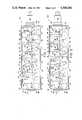
- FIGS. 1 and 2are elevational views with a side wall removed of a pump made in accordance with the present invention, only the timing of the pumps differing from each other.
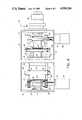
- FIG. 3is an enlarged elevational view with one side wall removed of the end portions of the pump of FIG. 1.
- FIG. 4is a plan view with the cover removed and partly in section of the pump end portions of FIG. 3.
- a preferred embodiment of the present inventionis for moving a material of high viscosity and which is highly self adhesive, such as raw dough.
- a pump in accordance with the present inventionis not limited to moving such dough but can also be used for pumping water and materials with a low viscosity within a viscosity range of from water to raw dough.
- a pumpmade in accordance with the present invention, has a housing 10 formed by a pair of spaced side walls 12 and 13, and end walls 14 and 15 all connected together and to a bottom wall 11 to define a chamber 17 closed at the top by a sealed cover 16.
- a frame 20is disposed in the chamber 17 providing a conduit support surface 21 spaced from the bottom wall 11 and a laterally spaced pair of side walls which extend from the support surface 21 to the cover 16.
- Each side wallis formed by a series of equally spaced block members 22, 23, 24, 25, 26, 27, 28 and 29, disposed from one end of the surface 21 to the opposite end thereof, the interspaces between block members forming an equally spaced series of vertical guide surfaces or tracks 30, 31, 32, 33, 34, 35 and 36.
- the spaced block members 22 . . . 29 and the formed tracks or guide surfaces 30 . . . 36 of one side wallare laterally aligned with the corresponding block members and tracks of the other side wall.
- a pair of skirt sections 21'comprising opposed parallel walls depending from each edge of surface 21 and extending to the bottom wall 11.
- a flexible conduit 37disposed on the support surface 21, is provided with an inlet connection 38 at the end wall 14 and an outlet or discharge connection 39 at the end wall 15.
- the axes of the inlet 38 and outlet 39are offset below the axis of the conduit 37 disposed on the support surface to prevent linear stresses at the ends of the conduit as will be further discussed.
- a plurality of pressure shoes 40, 41, 42, 43, 44, 45 and 46are disposed in a series within the side walls of frame 20 on the conduit 37 and have upwardly disposed stems 50, 51, 52, 53, 54, 55 and 56 which are generally rectangular in cross-section and extend laterally past the respective pressure shoes and into respective guide surfaces or tracks 30 . . . 36. Movement of the stems 50 . . . 56 in the vertical guide surfaces or tracks 30 . . . 36 causes the pressure shoes 40 . . . 46 to move in linear paths on axes normal to the axis of the flexible conduit and also prevent the pressure shoes from pendulum movement thereby preventing creation of linear stresses in the conduit 37.
- a set of links or arms 60, 61, 62, 63, 64, 65 and 66are pivotally connected to each end of the corresponding stems 50 . . . 56.
- the skirt portion 21' of the frame 20, which extends from the support surface 21 toward the bottom wall 11supports a plurality of laterally spaced pairs of gears 70, 71, 72, 73, 74, 75 and 76 sequentially in mesh with one another forming a gear train on both sides of the frame 20.
- Gears 70 . . . 76rotate on fixed centers and the links 60 . . . 66 are pivotally connected to respective gears each at a distance from the gear center of rotation equal to one half the vertical stroke or distance of movement of the respective pressure shoe.
- the gears 70 . . . 76thus act as crank arms moving links 60 . . . 66 to simultaneously drive both sides of stems 50 . . . 56 and prevent pressure shoes 40 . . . 46 from cocking and jamming as they move forward and away from the conduit 37.
- a motor 80mounted adjacent the inlet end of the housing 10, drives a vacuum pump 81 and is provided with a pair of spaced gears 82 in mesh with gears 70.
- a motor 85mounted adjacent the discharge end of the housing 10, drives a vacuum pump 86 and is provided with a pair of spaced gears 87 in mesh with gears 76.
- Driving the gear trains from both endstends to equalize the loading on the gears and eliminates any backlash between the gears.
- the vacuum pumps 81 and 86are connected to create low pressure in the chamber 17 for reinflating the flexible conduit 37 after compression and creating suction in the conduit at the inlet connection 38.
- a wire reinforced conduitfor example, as disclosed by Muehleck U.S. Pat. No. 2,280,252, Smith et al U.S. Pat. No. 2,405,909 or Parr U.S. Pat. No. 3,296,047, utilizing spring wire may be provided which by reference are made part of the present disclosure.
- pump 10is particularly adapted for pumping high viscosity material wherein the pressure shoes 40 . . . 46 incrementally trail the preceeding shoe so when shoe 40 is in the fully open conduit position, the shoe 46 fully closes the conduit 38. This is accomplished by progressively offsetting in a trailing direction the connections of the links 60 . . . 66 to gears 70 . . . 76 by 30°. Each of the gears 70 . . . 76 rotates in a direction opposite to the direction of rotation of the adjacent gears. Therefore, each link to gear connection not at 0° or 180° will be on the side opposite from the adjacent link to gear connection.
- a compressible pad or mat 69is provided on the support surface 21.
- a pressure shoewill fully close the conduit 37 from 71/2° to 15° before the link to gear connection arrives at the 180° position and maintains the closure for an equal distance thereafter.
- the vertical movement of the pressure shoe during this periodwill cause localized displacement of the pad 69.
- Thisprovides the shoes with a dwell time maintaining a closure by each shoe until the following shoe creates the next established closure.
- the arms or links 60 . . . 66may be made in the form of spring loaded members which lengthen against a spring bias, as each pressure shoe approaches the conduit closing position.
- conduit 37 of pump 10is open, is during the half cycle when shoe 40 is moving from the conduit open to closed position and shoe 46 is simultaneously moving from the conduit closed to open position. This was not found to be detrimental when moving highly viscous material. However, it may be desirable to provide a check valve 18 in the discharge 39 as shown to insure against back flow. It has been found that the check valve 18 enhances the pump operation to a greater degree when lower viscosity materials are being moved.
- pump 10A of FIG. 2The construction of pump 10A of FIG. 2 is the same as the construction of pump 10 of FIG. 1. The only differences between the pumps as shown are the timing sequences and configurations. Unlike with pump 10, it should be readily seen that with the timing configuration of pump 10A the flow path is never open or a short circuit condition cannot exist for any extended period of time.
- the conduit 37 of pump 10Acan be open at most only momentarily if the dwell times of two adjacent shoes do not overlap. In this arrangement, the link to gear connections are spaced 60° apart in a trailing direction and, if desired, the check valve 18 again may be included. Because of the timing arrangement, the undulations of the conduit 37 are much more rapid and are for briefer periods in pump 10A than in pump 10 which makes pump 10A of FIG. 2 more adapted for handling lower viscosity materials.
Landscapes
- Engineering & Computer Science (AREA)
- Mechanical Engineering (AREA)
- General Engineering & Computer Science (AREA)
- Reciprocating Pumps (AREA)
Abstract
Description
Claims (11)
Priority Applications (1)
| Application Number | Priority Date | Filing Date | Title |
|---|---|---|---|
| US06/559,004US4500266A (en) | 1981-09-24 | 1983-12-08 | Linear peristaltic pump |
Applications Claiming Priority (2)
| Application Number | Priority Date | Filing Date | Title |
|---|---|---|---|
| US30501181A | 1981-09-24 | 1981-09-24 | |
| US06/559,004US4500266A (en) | 1981-09-24 | 1983-12-08 | Linear peristaltic pump |
Related Parent Applications (1)
| Application Number | Title | Priority Date | Filing Date |
|---|---|---|---|
| US30501181AContinuation | 1981-09-24 | 1981-09-24 |
Publications (1)
| Publication Number | Publication Date |
|---|---|
| US4500266Atrue US4500266A (en) | 1985-02-19 |
Family
ID=26974353
Family Applications (1)
| Application Number | Title | Priority Date | Filing Date |
|---|---|---|---|
| US06/559,004Expired - Fee RelatedUS4500266A (en) | 1981-09-24 | 1983-12-08 | Linear peristaltic pump |
Country Status (1)
| Country | Link |
|---|---|
| US (1) | US4500266A (en) |
Cited By (5)
| Publication number | Priority date | Publication date | Assignee | Title |
|---|---|---|---|---|
| US5447417A (en)* | 1993-08-31 | 1995-09-05 | Valleylab Inc. | Self-adjusting pump head and safety manifold cartridge for a peristaltic pump |
| US6189736B1 (en) | 1997-01-17 | 2001-02-20 | Niagara Pump Corporation | Condiment dispensing apparatus |
| US20040037723A1 (en)* | 2002-07-06 | 2004-02-26 | B. Braun Melsungen Ag | Peristaltic hose pump |
| US20100111733A1 (en)* | 2008-10-31 | 2010-05-06 | John Ramunas | Peristaltic pump with constrictions at fixed locations |
| WO2016030868A3 (en)* | 2014-08-29 | 2016-04-28 | Leo Bühler | Elastic pump for a peristaltic pump, peristaltic pump for guiding flowable masses or powder, portioning unit for portioning flowable masses or powder, arrangement comprising several portioning units of said type, method for portioning flowable masses or powder |
Citations (19)
| Publication number | Priority date | Publication date | Assignee | Title |
|---|---|---|---|---|
| SU182874A1 (en)* | Научно исследовательский институт экспериментальной хирургической | PERFUSION PUMP OF FINGER TYPE | ||
| GB369037A (en)* | 1931-04-22 | 1932-03-17 | Yoshinobu Wada | Improvements in or relating to a pumping apparatus for medical treatments |
| GB637429A (en)* | 1948-05-04 | 1950-05-17 | John Fox Jennens Malone | Improvements relating to pumps, compressors and the like |
| US2877714A (en)* | 1957-10-30 | 1959-03-17 | Standard Oil Co | Variable displacement tubing pump |
| GB829329A (en)* | 1957-04-30 | 1960-03-02 | Apex Construction Company Ltd | Improvements relating to flexible tube pumps |
| GB923443A (en)* | 1960-11-21 | 1963-04-10 | Medtec Tools Ltd | Flexible tube pump |
| US3180272A (en)* | 1963-07-09 | 1965-04-27 | Roger L Culbertson | Deformable-hose fluid pump |
| US3296047A (en)* | 1962-05-25 | 1967-01-03 | Carlisle Tire And Rubber Divis | Method of producing reinforced flexible hose |
| GB1182908A (en)* | 1967-11-14 | 1970-03-04 | Polymetron A G | A Hose Pump. |
| GB1228093A (en)* | 1969-03-21 | 1971-04-15 | ||
| US3687580A (en)* | 1969-05-31 | 1972-08-29 | Griffiths Fuel Injection Dev L | Apparatus capable of use as a pump or a motor |
| GB1287951A (en)* | 1969-06-12 | 1972-09-06 | ||
| US3693382A (en)* | 1970-03-04 | 1972-09-26 | Frederick W Grantham | Continuous washing apparatus |
| US3778195A (en)* | 1972-07-20 | 1973-12-11 | G Bamberg | Pump for parenteral injections and the like |
| DE2454763A1 (en)* | 1973-11-23 | 1975-05-28 | Bjoerklund Knut Bertil | METHOD AND DEVICE FOR MEASURING |
| GB1450879A (en)* | 1973-11-13 | 1976-09-29 | Ici Australia Ltd | Peristaltic pumps |
| GB2006347A (en)* | 1977-10-13 | 1979-05-02 | Boehringer Mannheim Gmbh | Peristaltic fluid-machines |
| GB1572592A (en)* | 1977-06-13 | 1980-07-30 | Edwards J | Peristaltic pumps |
| US4294802A (en)* | 1979-02-27 | 1981-10-13 | Henry Johansson | Apparatus for parallel feeding of small volumes of fluids in several essentially parallel flexible hoses |
- 1983
- 1983-12-08USUS06/559,004patent/US4500266A/ennot_activeExpired - Fee Related
Patent Citations (20)
| Publication number | Priority date | Publication date | Assignee | Title |
|---|---|---|---|---|
| SU182874A1 (en)* | Научно исследовательский институт экспериментальной хирургической | PERFUSION PUMP OF FINGER TYPE | ||
| GB369037A (en)* | 1931-04-22 | 1932-03-17 | Yoshinobu Wada | Improvements in or relating to a pumping apparatus for medical treatments |
| GB637429A (en)* | 1948-05-04 | 1950-05-17 | John Fox Jennens Malone | Improvements relating to pumps, compressors and the like |
| GB829329A (en)* | 1957-04-30 | 1960-03-02 | Apex Construction Company Ltd | Improvements relating to flexible tube pumps |
| US2877714A (en)* | 1957-10-30 | 1959-03-17 | Standard Oil Co | Variable displacement tubing pump |
| GB923443A (en)* | 1960-11-21 | 1963-04-10 | Medtec Tools Ltd | Flexible tube pump |
| US3296047A (en)* | 1962-05-25 | 1967-01-03 | Carlisle Tire And Rubber Divis | Method of producing reinforced flexible hose |
| US3180272A (en)* | 1963-07-09 | 1965-04-27 | Roger L Culbertson | Deformable-hose fluid pump |
| GB1182908A (en)* | 1967-11-14 | 1970-03-04 | Polymetron A G | A Hose Pump. |
| GB1228093A (en)* | 1969-03-21 | 1971-04-15 | ||
| US3687580A (en)* | 1969-05-31 | 1972-08-29 | Griffiths Fuel Injection Dev L | Apparatus capable of use as a pump or a motor |
| GB1287951A (en)* | 1969-06-12 | 1972-09-06 | ||
| US3693382A (en)* | 1970-03-04 | 1972-09-26 | Frederick W Grantham | Continuous washing apparatus |
| GB1357161A (en)* | 1970-03-04 | 1974-06-19 | Grantham F W | Laundry apparatus and method including continuous washing ex tracting and drying |
| US3778195A (en)* | 1972-07-20 | 1973-12-11 | G Bamberg | Pump for parenteral injections and the like |
| GB1450879A (en)* | 1973-11-13 | 1976-09-29 | Ici Australia Ltd | Peristaltic pumps |
| DE2454763A1 (en)* | 1973-11-23 | 1975-05-28 | Bjoerklund Knut Bertil | METHOD AND DEVICE FOR MEASURING |
| GB1572592A (en)* | 1977-06-13 | 1980-07-30 | Edwards J | Peristaltic pumps |
| GB2006347A (en)* | 1977-10-13 | 1979-05-02 | Boehringer Mannheim Gmbh | Peristaltic fluid-machines |
| US4294802A (en)* | 1979-02-27 | 1981-10-13 | Henry Johansson | Apparatus for parallel feeding of small volumes of fluids in several essentially parallel flexible hoses |
Cited By (8)
| Publication number | Priority date | Publication date | Assignee | Title |
|---|---|---|---|---|
| US5447417A (en)* | 1993-08-31 | 1995-09-05 | Valleylab Inc. | Self-adjusting pump head and safety manifold cartridge for a peristaltic pump |
| US6189736B1 (en) | 1997-01-17 | 2001-02-20 | Niagara Pump Corporation | Condiment dispensing apparatus |
| US6213739B1 (en) | 1997-01-17 | 2001-04-10 | Niagara Pump Corporation | Linear peristaltic pump |
| US20040037723A1 (en)* | 2002-07-06 | 2004-02-26 | B. Braun Melsungen Ag | Peristaltic hose pump |
| US7217108B2 (en) | 2002-07-06 | 2007-05-15 | B. Braun Melsungen Ag | Peristaltic hose pump |
| US20100111733A1 (en)* | 2008-10-31 | 2010-05-06 | John Ramunas | Peristaltic pump with constrictions at fixed locations |
| US8382460B2 (en) | 2008-10-31 | 2013-02-26 | The Board Of Trustees Of The Leland Stanford Junior University | Peristaltic pump with constrictions at fixed locations |
| WO2016030868A3 (en)* | 2014-08-29 | 2016-04-28 | Leo Bühler | Elastic pump for a peristaltic pump, peristaltic pump for guiding flowable masses or powder, portioning unit for portioning flowable masses or powder, arrangement comprising several portioning units of said type, method for portioning flowable masses or powder |
Similar Documents
| Publication | Publication Date | Title |
|---|---|---|
| US3981633A (en) | Pump | |
| KR100907118B1 (en) | Material transfer process and apparatus | |
| US7040869B2 (en) | Method and device for conveying media | |
| US5145339A (en) | Pulseless piston pump | |
| US1580479A (en) | Diaphragm pump | |
| CN100513783C (en) | Multi-stage diaphragm pump | |
| US4500266A (en) | Linear peristaltic pump | |
| US3870437A (en) | Planetary gear pump | |
| GB2106994A (en) | Peristaltic pumps | |
| US4145166A (en) | Displacement pump | |
| SU941672A1 (en) | Diaphragm pump | |
| EP0486556B1 (en) | Pulseless piston pump | |
| US4202657A (en) | Fluid pump | |
| US4645434A (en) | Device in a peristaltic pump | |
| US3956893A (en) | Hydraulic power transmission | |
| US3905726A (en) | Planetary gear pump | |
| US3058625A (en) | Material handling slide valve | |
| US921164A (en) | Compressor, vacuum-pump, and the like. | |
| US4386889A (en) | Radial wave pump | |
| US344445A (en) | Maul on haeeold | |
| US11852017B2 (en) | Piston machine, modular construction system for a piston machine, and method for producing a piston machine | |
| JPH11280649A (en) | Multiple stage compressor | |
| SU1767227A1 (en) | Positive-displacement rotary machine | |
| AU2007201728B2 (en) | Method and Device for Conveying Media | |
| GB2057059A (en) | Rotary positive-displacement fluid-machines |
Legal Events
| Date | Code | Title | Description |
|---|---|---|---|
| AS | Assignment | Owner name:AMF INCORPORATED, A NJ CORP. Free format text:ASSIGNMENT OF ASSIGNORS INTEREST.;ASSIGNOR:CUMMINS, DONALD L.;REEL/FRAME:004297/0793 Effective date:19810918 | |
| AS | Assignment | Owner name:AMF UNION MACHINERY INC., 2115 WEST LABURNUM AVENU Free format text:ASSIGNMENT OF ASSIGNORS INTEREST.;ASSIGNOR:AMF INCORPORATED, A CORP OF N.J.;REEL/FRAME:004486/0638 Effective date:19851111 | |
| AS | Assignment | Owner name:BANK OF VIRGINIA, 800 E. MAIN STREET, RICHMOND, VA Free format text:SECURITY INTEREST;ASSIGNOR:AUTOMATED MACHINERY SYSTEMS, INC, A CORP. OF VA.;REEL/FRAME:004495/0269 Effective date:19860110 | |
| AS | Assignment | Owner name:AUTOMATED MACHINERY SYSTEMS, INC. A CORP OF VA Free format text:MERGER;ASSIGNOR:AMF UNION MACHINERY INC., A DE CORP. (INTO);REEL/FRAME:004647/0149 Effective date:19861022 | |
| REMI | Maintenance fee reminder mailed | ||
| LAPS | Lapse for failure to pay maintenance fees | ||
| STCH | Information on status: patent discontinuation | Free format text:PATENT EXPIRED DUE TO NONPAYMENT OF MAINTENANCE FEES UNDER 37 CFR 1.362 | |
| FP | Lapsed due to failure to pay maintenance fee | Effective date:19890219 |