US4498193A - Jammer transmitter - Google Patents
Jammer transmitterDownload PDFInfo
- Publication number
- US4498193A US4498193AUS06/509,397US50939783AUS4498193AUS 4498193 AUS4498193 AUS 4498193AUS 50939783 AUS50939783 AUS 50939783AUS 4498193 AUS4498193 AUS 4498193A
- Authority
- US
- United States
- Prior art keywords
- signals
- fed
- transmitter
- comb spectrum
- aerial
- Prior art date
- Legal status (The legal status is an assumption and is not a legal conclusion. Google has not performed a legal analysis and makes no representation as to the accuracy of the status listed.)
- Expired - Lifetime
Links
- 238000001228spectrumMethods0.000claimsabstractdescription36
- 230000008878couplingEffects0.000claims1
- 238000010168coupling processMethods0.000claims1
- 238000005859coupling reactionMethods0.000claims1
- 230000005540biological transmissionEffects0.000description4
- 238000004891communicationMethods0.000description4
- 238000010586diagramMethods0.000description3
- 238000000034methodMethods0.000description3
- 239000003990capacitorSubstances0.000description2
- 238000012986modificationMethods0.000description2
- 230000004048modificationEffects0.000description2
- 238000011084recoveryMethods0.000description2
- 230000001427coherent effectEffects0.000description1
- 239000012141concentrateSubstances0.000description1
- 230000000694effectsEffects0.000description1
Images

Classifications
- H—ELECTRICITY
- H04—ELECTRIC COMMUNICATION TECHNIQUE
- H04K—SECRET COMMUNICATION; JAMMING OF COMMUNICATION
- H04K3/00—Jamming of communication; Counter-measures
- H04K3/40—Jamming having variable characteristics
- H04K3/42—Jamming having variable characteristics characterized by the control of the jamming frequency or wavelength
- A—HUMAN NECESSITIES
- A61—MEDICAL OR VETERINARY SCIENCE; HYGIENE
- A61K—PREPARATIONS FOR MEDICAL, DENTAL OR TOILETRY PURPOSES
- A61K38/00—Medicinal preparations containing peptides
- H—ELECTRICITY
- H04—ELECTRIC COMMUNICATION TECHNIQUE
- H04K—SECRET COMMUNICATION; JAMMING OF COMMUNICATION
- H04K3/00—Jamming of communication; Counter-measures
- H04K3/40—Jamming having variable characteristics
- H04K3/41—Jamming having variable characteristics characterized by the control of the jamming activation or deactivation time
- H—ELECTRICITY
- H04—ELECTRIC COMMUNICATION TECHNIQUE
- H04K—SECRET COMMUNICATION; JAMMING OF COMMUNICATION
- H04K3/00—Jamming of communication; Counter-measures
- H04K3/40—Jamming having variable characteristics
- H04K3/45—Jamming having variable characteristics characterized by including monitoring of the target or target signal, e.g. in reactive jammers or follower jammers for example by means of an alternation of jamming phases and monitoring phases, called "look-through mode"
Definitions
- This inventionrelates to transmitters and more especially it relates to R.F. (radio frequency) jammers.
- R.F. jammersseek to provide an R.F. signal which interferes with radio communication to an extent which renders the reception of intelligence difficult if not impossible.
- the power required to jam a radio communication linkdepends principally on the range of the radio receiver to be jammed and the bandwidth used by the radio receiver to be jammed. Thus a local receiver using a narrow bandwidth may be jammed with a comparatively small radiated jamming signal whereas a distant communication link occupying a wide bandwidth would require a comparatively large radiated jamming signal if jamming were to be effective.
- Frequency hoppingrequires a radio frequency to be changed or hopped periodically so that a transmission is in effect distributed over a wide bandwidth although occupying instantaneously a comparatively narrow bandwidth only. It is not easy to design a jammer which will hop synchronously with the signal to be jammed, and saturation jamming over a wide band has inherent serious disadvantages. Frequency hopping transmissions are therefore not easy to jam effectively and hitherto an effective cheap and simple jammer has not been available. It is an object of the present invention to provide such a jammer.
- a jammer transmittercomprises a comb spectrum generator which includes pulse generator means adapted to produce a pulse train at a frequency corresponding to the channel spacing of signals to be jammed, and a bandpass filter which has a passband including or controllable to include, a bandwidth occupied by the signals to be jammed and which is responsive to the pulse train for providing within this bandwidth comb generator output signals at harmonics of the pulse train frequency, a power amplifier operative to amplify the comb generator output signals so as to produce jamming pulses and aerial means for radiating the jamming pulses, the width of the pulses of the pulse train being short enough to ensure that the harmonics of the pulse train frequency occur throughout the said bandwidth.
- the pulse generator meansmay comprise an oscillator arranged to provide a signal at the channel spacing frequency and a monostable device responsive to the oscillator for producing the said pulse train.
- the monostable devicemay be a monostable multivibrator or alternatively it may comprise a step recovery diode.
- the monostable devicemay be arranged to feed the bandpass filter via an amplifier.
- the bandpass filtermay be controllable to afford various passbands which may be adjacent and contiguous thereby to cover a predetermined frequency band in steps.
- the jammermay be contained within a case including a battery compartment.
- the casemay be adapted to fit into an aerial transportation vehicle.
- This vehiclemay be an unpowered shell, glider, or projectile, or alternatively it may be powered by means of a rocket engine or some other engine arranged to drive an air screw.
- the vehiclemay be equipped with a deployable parachute for landing purposes.
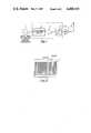
- FIG. 1is a generally schematic block diagram of a jammer
- FIG. 2is a waveform diagram showing waveforms generated by the jammer shown in FIG. 1 and in which;
- FIG. 3is a somewhat schematic block diagram of a more complex jammer incorporating the jammer of FIG. 1.
- the jammercomprises an oscillator 1 which is arranged to produce a signal at 25 kHz which corresponds to the channel spacing of signals to be jammed.
- the oscillator 1is arranged to feed a monostable device 2, which may be a monostable multivibrator or a step recovery diode for example, which serves to convert the signal from the oscillator into a corresponding train of 30 nanosecond pulses and thus the frequency of the pulse train corresponds to the frequency of the oscillator 1 i.e. 25 kHz.
- Output signals from the monostable device 2are fed to an amplifier 3, and the amplifier 3 is arranged to feed a controllable bandpass filter 4.
- the passband of the filter 4is 30 to 90 mHz and since the pulse width of the pulses is only 30 nanoseconds, harmonics of the pulse train frequency of 25 kHz will extend throughout the 30 to 90 mHz band. It will be appreciated by those skilled in the art that the shorter the pulses produced by the monostable device 2, the further out into the high frequency spectrum will the harmonics potentially extend. And conversely harmonics from longer pulses will not extend so far into the frequency spectrum. Thus if for example one microsecond pulses were generated, the harmonics would probably not extend much beyond 10 mHz, whereas if pulses shorter than 30 nanoseconds were used, a band higher than 90 mHz would be covered.
- the signal produced at the output of the filter 4thus comprises jamming signals spaced apart by the channel spacing frequency i.e. 25 kHz which extend throughout the 30 to 90 mHz band and which therefore may be described as a comb spectrum.
- the monostable device 2, the amplifier 3 and the filter 4, which are enclosed by a broken linemay thus be described as a comb spectrum generator 9.
- the jamming pulse train produced by the comb spectrum generator 9is fed to a power amplifier 5 which is arranged to feed a transmission aerial 6.
- the comb spectrum radiated from the aerial 6is shown in FIG. 2 and comprises a plurality of signals 7 which extend throughout the 30 to 90 mhz band and which are spaced apart by 25 kHz.
- the bandpass filter 4may be switchable to cover a wide bandwidth in steps.
- FIG. 3utilizes the basic elements of the jammer described with reference to FIG. 1 but which is arranged to radiate jamming signals only when a signal to be jammed is present.
- the jammercomprises three comb spectrum generators 9a, 9b and 9c which cover in combination a frequency band to be jammed.
- the comb spectrum generator 9acovers the 30 to 50 MHz band
- the comb spectrum generator 9bcovers the 50 to 70 MHz band
- the comb spectrum generator 9ccovers the 70 to 90 MHz band.
- the jammer of FIG. 3includes both the power amplifier 5 and the aerial 6 shown in FIG. 1, but as will hereinafter be described, one or other or all of the comb spectrum generators 9a, 9b and 9c may be arranged to feed the aerial 6 via the power amplifiers.
- the arrangement and operation of apparatus operatively associated with the comb spectrum generators 9a, 9b and 9cis similar and therefore the operation of the apparatus associated with the comb generator 9a only will be described in detail.
- Signals from the comb generator 9aare fed via a line 10a to a mixer 11a to which received signals are fed via a line 12a from the aerial 6 via a diplexer 13.
- a line 14aWhen the frequency of received line 12a falls within the bandwidth covered by the comb spectrum generator 9a low frequency resultant signals will be produced on a line 14a at the output of the mixer 11a which is arranged to feed a low pass filter 15a via a capacitor 16a.
- the pass band of the filter 15ais arranged to be such that signals are passed by the filter only when the frequency of received signals on the line 12a is such as to correspond with or nearly correspond with the frequency of a signal produced by the comb generator 9a.
- Output signals from the filter 15aare fed via an amplifier 17a to a demodulator 18a.
- Signals from the demodulatorare fed via a line 19a to a switch 20a.
- the switch 20ais operated so that signals from the comb spectrum generator 9a produced on a line 21a are fed via the switch 20a to a combiner 22, output signals from which are fed to the amplifier 5.
- Amplified signals produced by the comb spectrum generator 9aare fed via the diaplexer 13 to the aerial 6 to be radiated as a jamming signal.
- signals from the comb spectrum generator 9aare fed to the power amplifier 5 only when a signal is received via the aerial 6 which falls within the frequency spectrum covered by the comb spectrum generator 9a.
- the comb spectrum generators 9a, 9b and 9ceach cover separate adjacent frequency bands and have operatively associated with them similar apparatus corresponding parts of which bear the same numerical designations, the various parts being distinguished by the suffixes a, b, or c, in accordance with the comb spectrum generator with which they are operatively associated.
- the lines 12a, 12b, and 12care arranged to feed the mixers 11a 11b and 11c respectively which are operatively associated with the comb generators 9a, 9b and 9c respectively.
- signals from the comb spectrum generator 9awill be fed via the switch 20a and the combiner 22 to the amplifier 5 and similarly if a signal in the frequency band 30 to 70 MHz is received the switch 20b will be operated and signals from the comb spectrum generator 9b will be fed via the combiner 22 and the amplifier 5 through the diplexer 13 to the aerial 6 for jamming purposes.
- signalswill be radiated throughout the whole of the 30 to 90 MHz band if the whole band is used by a frequency hopping transmitter or transmitters and in this case all three of the comb spectrum generators 9a, 9b, and 9c will be used.
- any two or any one of the comb spectrum generatorsmay be used in accordance with the frequency of signals received.
- the arrangement shown in FIG. 3has the advantage that locally generated signals are not fed back to operate the switches 20a, 20b and 20c. This is because signals fed back from the amplifier 5 via the diplexer 13 to the mixers 11a, 11b and 11c are coherent with the signals fed to the mixers 11a, 11b and 11c on the lines 10a, 10b and 10c, and thus the resultant signals prouced on the lines 14a, 14b and 14c at the output of the mixers will be d.c. signals which will blocked by the capacitors 16a, 16b and 16c.
- the diplexer 13is a signal splitter which affords a higher impedance path to signals fed from the amplifiers 5 to the mixers 12a, 12b and 12c than to signals fed from the amplifier 5 to the aerial 6, whereby saturation of the mixers is avoided.
- a decoder 23is included which is responsive to predetermined coded signals which in the present example are transmitted in the 30 to 50 MHz band so as to appear on the line 19a at the output of the demodulator 18a. Signals from the decoder 23 are arranged to operate one or other or all of the switches 20a, 20b, or 20c to turn the switches ⁇ ON ⁇ or ⁇ OFF ⁇ , in dependance upon the coded signals transmitted and received on the line 19a.
- a jammermay be delivered to a remote location and controlled remotely by means of transmitted coded signals.
- a jammer as just before described with reference to FIG. 3has the advantage that the power amplifier 5 is utilized for jamming purposes only when predetermined signals to be jammed are received. Apart from effecting a significant power economy, this feature renders the jammer difficult to detect since the jammer operates only in the presence of a signal to be jammed and this will tend to confuse direction finding equipment.
- the decoder 23may be arranged to control operation of the power amplifier directly.
- a threshold gate or gatesmay be included whereby the jammer will operate only in the presence of received signals above a predetermined amplitude and the demodulation 18a, 18b and 18c may for example be arranged to feed the switches 20a, 20b and 20c via threshold gates.
- jamming poweris peaked throughout the frequency band of significance at intervals corresponding to the channel spacing of the signals to be jammed. It will be appreciated therefore that a radio receiver hopping at frequencies within a predetermined band covered by the jammer will find no channel which is free from interference. It will also be appreciated that since a jammer according to the invention concentrates the available power into slots which are spaced apart at intervals throughout the band, high power as would be required for saturation jamming to cover the same frequency band, is not required. It will also be appreciated that a jammer according to the present invention can be made which is small, cheap and robust. Thus jammers according to the present invention may be expendable and delivered in a projectile to a precise location in the proximity of a receiver to be jammed.
Landscapes
- Engineering & Computer Science (AREA)
- Computer Networks & Wireless Communication (AREA)
- Signal Processing (AREA)
- Noise Elimination (AREA)
- Radar Systems Or Details Thereof (AREA)
Abstract
Description
Claims (8)
Applications Claiming Priority (4)
| Application Number | Priority Date | Filing Date | Title |
|---|---|---|---|
| GB8219063 | 1982-07-01 | ||
| GB8219063 | 1982-07-01 | ||
| GB08233226AGB2123256B (en) | 1982-11-22 | 1982-11-22 | Radio communication jamming transmitter |
| GB8233226 | 1982-11-22 |
Publications (1)
| Publication Number | Publication Date |
|---|---|
| US4498193Atrue US4498193A (en) | 1985-02-05 |
Family
ID=26283242
Family Applications (1)
| Application Number | Title | Priority Date | Filing Date |
|---|---|---|---|
| US06/509,397Expired - LifetimeUS4498193A (en) | 1982-07-01 | 1983-06-30 | Jammer transmitter |
Country Status (5)
| Country | Link |
|---|---|
| US (1) | US4498193A (en) |
| DE (1) | DE3322325A1 (en) |
| FR (1) | FR2529736B1 (en) |
| IT (1) | IT1163621B (en) |
| NL (1) | NL8301943A (en) |
Cited By (48)
| Publication number | Priority date | Publication date | Assignee | Title |
|---|---|---|---|---|
| US4901348A (en)* | 1985-12-24 | 1990-02-13 | American Telephone And Telegraph Company | Data transmission security arrangement for a plurality of data stations sharing access to a communication network |
| US4912760A (en)* | 1988-03-10 | 1990-03-27 | Scientific Atlanta, Inc. | Off-premises cable television channel interdiction method and apparatus |
| US5001771A (en)* | 1987-05-27 | 1991-03-19 | British Aerospace Public Limited Company | Communications jammer |
| US5014309A (en)* | 1988-03-10 | 1991-05-07 | Scientific-Atlanta, Inc. | Off-premises cable television channel interdiction method and apparatus |
| US5142574A (en)* | 1988-03-10 | 1992-08-25 | West Jr Lamar | Optimum amplitude and frequency of jamming carrier in interdiction program denial system |
| US5208854A (en)* | 1988-03-10 | 1993-05-04 | Scientific-Atlanta, Inc. | Picture carrier controlled automatic gain control circuit for cable television interdiction or jamming apparatus |
| US5265160A (en)* | 1992-06-10 | 1993-11-23 | Scientific-Atlanta, Inc. | Interdiction method and apparatus with pulsed mode jamming |
| US5278908A (en)* | 1992-06-10 | 1994-01-11 | Scientific-Atlanta, Inc. | Interdiction method and apparatus with programmable jamming effectiveness |
| US5287539A (en)* | 1988-03-10 | 1994-02-15 | Scientific-Atlanta, Inc. | Interdiction program denial system for jamming audio and video signals |
| US5289541A (en)* | 1988-03-10 | 1994-02-22 | Scientific-Atlanta, Inc. | Interdiction method and apparatus with constant blanking and variable dwell times |
| US5303295A (en)* | 1988-03-10 | 1994-04-12 | Scientific-Atlanta, Inc. | Enhanced versatility of a program control by a combination of technologies |
| US5317635A (en)* | 1992-06-10 | 1994-05-31 | Scientific-Atlanta, Inc. | Interdiction method and apparatus with mode control for variable frequency elements |
| US5323462A (en)* | 1988-03-10 | 1994-06-21 | Scientific-Atlanta, Inc. | CATV subscriber disconnect switch |
| US5341424A (en)* | 1992-06-10 | 1994-08-23 | Scientific-Atlanta, Inc. | Interdiction method and apparatus with frequency change inhibit function |
| US5361301A (en)* | 1992-06-10 | 1994-11-01 | Scientific-Atlanta, Inc. | Interdiction method and apparatus with direct memory control of variable frequency elements |
| US5463689A (en)* | 1988-03-10 | 1995-10-31 | Scientific-Atlanta | Interdiction method and apparatus with random mode jamming |
| US5594458A (en)* | 1989-12-11 | 1997-01-14 | Oesterreichisches Forschungszentrum Seibersdorf Ges.M.B.H. | Comb generator, device and process for calibrating measurement sections |
| US6112052A (en)* | 1997-01-29 | 2000-08-29 | Northrop Grumman Corporation | Remote controlled noise jamming device |
| US6195529B1 (en)* | 1998-03-12 | 2001-02-27 | Joachim Linz | Transmission blocker for mobile radio stations and method for preventing transmission activities of a mobile radio station |
| US6393254B1 (en)* | 1998-02-26 | 2002-05-21 | José María Pousada Carballo | Disabler for mobile communications |
| US20020102968A1 (en)* | 2001-01-26 | 2002-08-01 | Qwest Communications International Inc. | Wireless telecommunications signal inhibition |
| US6429768B1 (en)* | 1999-09-09 | 2002-08-06 | Kenneth E. Flick | Vehicle control system including transponder jammer and related methods |
| KR100357375B1 (en)* | 1999-07-05 | 2002-10-18 | 재밍일렉트로닉(주) | Jammer |
| KR100365514B1 (en)* | 2000-04-28 | 2002-12-18 | 주식회사 모든텔레콤 | Orthogonal call noise simulator |
| RU2220508C2 (en)* | 2001-03-12 | 2003-12-27 | Ставропольский государственный университет | Noise interference generation method |
| RU2224376C1 (en)* | 2002-06-07 | 2004-02-20 | Федеральное государственное унитарное предприятие Специальное конструкторское бюро Института радиотехники и электроники РАН | Radio masking device |
| RU2231231C1 (en)* | 2003-03-27 | 2004-06-20 | Государственный НИИИ проблем технической защиты информации Государственной технической комиссии при Президенте Российской Федерации | Device for protecting enclosed locations against unauthorized pickup of voice information |
| US20050020244A1 (en)* | 2003-07-23 | 2005-01-27 | Hyokang Chang | RF firewall for a wireless network |
| RU2276458C2 (en)* | 2003-11-26 | 2006-05-10 | Институт радиотехники и электроники Российской Академии Наук | Method for direct-chaotic information transfer with given spectrum mask |
| US20060264168A1 (en)* | 2005-05-19 | 2006-11-23 | Corbett Blaise L | Processor based frequency selective jamming and communications system |
| RU2292651C1 (en)* | 2005-09-20 | 2007-01-27 | Государственное образовательное учреждение высшего профессионального образования Военный институт радиоэлектроники | Method for creating non-modulated active interference for suppressing mobile communications inside a building |
| RU2300174C1 (en)* | 2006-01-10 | 2007-05-27 | Государственный научно-исследовательский испытательный институт проблем технической защиты информации Федеральной службы по техническому и экспортному контролю | Method for active reaction to optoelectronic television observation system |
| US20070268174A1 (en)* | 2006-03-17 | 2007-11-22 | Tmc Design Corporation | Jamming signal detector |
| RU2347238C1 (en)* | 2007-06-25 | 2009-02-20 | Государственное образовательное учреждение высшего профессионального образования Воронежское высшее военное авиационное инженерное училище (военный институт) | Device of contortion of radar-tracking image of object |
| RU2351077C2 (en)* | 2007-05-03 | 2009-03-27 | Государственное образовательное учреждение высшего профессионального образования Воронежское высшее военное авиационное инженерное училище (военный институт) | Method of generating active interference for suppressing mobile communication in multipath conditions |
| US20090209196A1 (en)* | 2006-03-07 | 2009-08-20 | Haverty James D | Methods of Suppressing GSM Wireless Device Threats in Dynamic or Wide Area Static Environments Using Minimal Power and Collateral Interference |
| US20090311963A1 (en)* | 2005-08-02 | 2009-12-17 | James D Haverty | Methods of Remotely Identifying, Suppressing, Disabling and Access Filtering Wireless Devices of Interest Using Signal Timing and Intercept Receivers to Effect Power Reduction, Minimization of Detection, and Minimization of Collateral Interfernce. |
| US20100226308A1 (en)* | 2006-08-15 | 2010-09-09 | Comhouse Wireless Lp | node- arbitrated media access control protocol for ad hoc broadcast networks carrying ephemeral information |
| US20100302956A1 (en)* | 2005-08-02 | 2010-12-02 | Comhouse Wireless Lp | Enhanced Methods of Cellular Environment Detection When Interoperating with Timed Interfers |
| US20100302087A1 (en)* | 2009-05-28 | 2010-12-02 | Lockheed Martin Corporation | Smart Signal Jammer |
| US20100304706A1 (en)* | 2006-08-01 | 2010-12-02 | Comhouse Wireless, Lp | Methods for Identifying Wireless Devices Connected to Potentially Threatening Devices |
| US20100309884A1 (en)* | 2009-07-29 | 2010-12-09 | ComHouse Wireless. LP | Methods for surreptitious manipulation of CDMA 2000 wireless devices |
| US20110059689A1 (en)* | 2009-09-04 | 2011-03-10 | Comhouse Wireless, Lp | Using code channel overrides to suppress CDMA wireless devices |
| EP1982210A4 (en)* | 2006-01-25 | 2012-04-18 | Bae Systems Bofors Ab | Method for creating interference, and jamming arrangement |
| US8522353B1 (en)* | 2007-08-15 | 2013-08-27 | Meru Networks | Blocking IEEE 802.11 wireless access |
| RU2497284C2 (en)* | 2011-11-15 | 2013-10-27 | федеральное автономное учреждение "Государственный научно-исследовательский испытательный институт проблем технической защиты информации Федеральной службы по техническому и экспортному контролю" | Method for functional jamming of digital electronic device |
| CN109698731A (en)* | 2019-01-29 | 2019-04-30 | 济南爱我本克网络科技有限公司 | A kind of Terahertz electromagnetic interference system and its application method |
| RU2732079C1 (en)* | 2019-09-18 | 2020-09-11 | Тимофей Андреевич Семенюк | Radio-controlled fuses locking device |
Families Citing this family (6)
| Publication number | Priority date | Publication date | Assignee | Title |
|---|---|---|---|---|
| DE3432350A1 (en)* | 1984-09-03 | 1986-03-13 | C. Plath Gmbh Nautisch-Elektronische Technik, 2000 Hamburg | COMB SPECTRUM OSCILLATOR |
| DE3432357C1 (en)* | 1984-09-03 | 1986-02-27 | C. Plath Gmbh Nautisch-Elektronische Technik, 2000 Hamburg | Method and device for receiving and direction finding transmitters operating according to the frequency hopping method |
| RU2131645C1 (en)* | 1998-05-26 | 1999-06-10 | Закрытое акционерное общество "Конструкторское опытное бюро радиоаппаратуры" (ЗАО "КОБРА") | Device for locking radio proximity fuses |
| RU2229198C1 (en)* | 2002-12-04 | 2004-05-20 | Военный университет связи | Method and device for jamming communication channels |
| RU2717229C1 (en)* | 2019-07-15 | 2020-03-19 | Тимофей Андреевич Семенюк | Apparatus for counteracting unauthorized transmission of control information |
| RU2717320C1 (en)* | 2019-08-29 | 2020-03-20 | Тимофей Андреевич Семенюк | Device for counteraction to radio-controlled explosive devices |
Citations (5)
| Publication number | Priority date | Publication date | Assignee | Title |
|---|---|---|---|---|
| US3774208A (en)* | 1968-10-24 | 1973-11-20 | Us Navy | Narrow band frequency modulated jammer |
| US3942179A (en)* | 1968-10-18 | 1976-03-02 | The United States Of America As Represented By The Secretary Of The Navy | Filtered-noise jammer |
| US4039954A (en)* | 1975-05-27 | 1977-08-02 | Oak Holland B.V. | Signal distribution device for a cable television |
| US4103236A (en)* | 1960-09-22 | 1978-07-25 | Siemens Aktiengesellschaft | Electronic jamming system |
| US4214208A (en)* | 1963-08-07 | 1980-07-22 | The United States Of America As Represented By The Secretary Of The Army | Jamming of keyed continuous wave radio signals |
Family Cites Families (1)
| Publication number | Priority date | Publication date | Assignee | Title |
|---|---|---|---|---|
| US3896439A (en)* | 1955-10-31 | 1975-07-22 | Sperry Rand Corp | Multi-spot radar jamming system |
- 1983
- 1983-06-01NLNL8301943Apatent/NL8301943A/ennot_activeApplication Discontinuation
- 1983-06-21DEDE19833322325patent/DE3322325A1/ennot_activeWithdrawn
- 1983-06-29ITIT21851/83Apatent/IT1163621B/enactive
- 1983-06-30FRFR838310924Apatent/FR2529736B1/ennot_activeExpired - Fee Related
- 1983-06-30USUS06/509,397patent/US4498193A/ennot_activeExpired - Lifetime
Patent Citations (5)
| Publication number | Priority date | Publication date | Assignee | Title |
|---|---|---|---|---|
| US4103236A (en)* | 1960-09-22 | 1978-07-25 | Siemens Aktiengesellschaft | Electronic jamming system |
| US4214208A (en)* | 1963-08-07 | 1980-07-22 | The United States Of America As Represented By The Secretary Of The Army | Jamming of keyed continuous wave radio signals |
| US3942179A (en)* | 1968-10-18 | 1976-03-02 | The United States Of America As Represented By The Secretary Of The Navy | Filtered-noise jammer |
| US3774208A (en)* | 1968-10-24 | 1973-11-20 | Us Navy | Narrow band frequency modulated jammer |
| US4039954A (en)* | 1975-05-27 | 1977-08-02 | Oak Holland B.V. | Signal distribution device for a cable television |
Cited By (61)
| Publication number | Priority date | Publication date | Assignee | Title |
|---|---|---|---|---|
| US4901348A (en)* | 1985-12-24 | 1990-02-13 | American Telephone And Telegraph Company | Data transmission security arrangement for a plurality of data stations sharing access to a communication network |
| US5001771A (en)* | 1987-05-27 | 1991-03-19 | British Aerospace Public Limited Company | Communications jammer |
| US5287539A (en)* | 1988-03-10 | 1994-02-15 | Scientific-Atlanta, Inc. | Interdiction program denial system for jamming audio and video signals |
| US5323462A (en)* | 1988-03-10 | 1994-06-21 | Scientific-Atlanta, Inc. | CATV subscriber disconnect switch |
| US5142574A (en)* | 1988-03-10 | 1992-08-25 | West Jr Lamar | Optimum amplitude and frequency of jamming carrier in interdiction program denial system |
| US5208854A (en)* | 1988-03-10 | 1993-05-04 | Scientific-Atlanta, Inc. | Picture carrier controlled automatic gain control circuit for cable television interdiction or jamming apparatus |
| US4912760A (en)* | 1988-03-10 | 1990-03-27 | Scientific Atlanta, Inc. | Off-premises cable television channel interdiction method and apparatus |
| US5014309A (en)* | 1988-03-10 | 1991-05-07 | Scientific-Atlanta, Inc. | Off-premises cable television channel interdiction method and apparatus |
| US5289541A (en)* | 1988-03-10 | 1994-02-22 | Scientific-Atlanta, Inc. | Interdiction method and apparatus with constant blanking and variable dwell times |
| US5303295A (en)* | 1988-03-10 | 1994-04-12 | Scientific-Atlanta, Inc. | Enhanced versatility of a program control by a combination of technologies |
| US5463689A (en)* | 1988-03-10 | 1995-10-31 | Scientific-Atlanta | Interdiction method and apparatus with random mode jamming |
| US5594458A (en)* | 1989-12-11 | 1997-01-14 | Oesterreichisches Forschungszentrum Seibersdorf Ges.M.B.H. | Comb generator, device and process for calibrating measurement sections |
| US5278908A (en)* | 1992-06-10 | 1994-01-11 | Scientific-Atlanta, Inc. | Interdiction method and apparatus with programmable jamming effectiveness |
| US5341424A (en)* | 1992-06-10 | 1994-08-23 | Scientific-Atlanta, Inc. | Interdiction method and apparatus with frequency change inhibit function |
| US5361301A (en)* | 1992-06-10 | 1994-11-01 | Scientific-Atlanta, Inc. | Interdiction method and apparatus with direct memory control of variable frequency elements |
| US5317635A (en)* | 1992-06-10 | 1994-05-31 | Scientific-Atlanta, Inc. | Interdiction method and apparatus with mode control for variable frequency elements |
| US5265160A (en)* | 1992-06-10 | 1993-11-23 | Scientific-Atlanta, Inc. | Interdiction method and apparatus with pulsed mode jamming |
| US6112052A (en)* | 1997-01-29 | 2000-08-29 | Northrop Grumman Corporation | Remote controlled noise jamming device |
| US6393254B1 (en)* | 1998-02-26 | 2002-05-21 | José María Pousada Carballo | Disabler for mobile communications |
| US6195529B1 (en)* | 1998-03-12 | 2001-02-27 | Joachim Linz | Transmission blocker for mobile radio stations and method for preventing transmission activities of a mobile radio station |
| KR100357375B1 (en)* | 1999-07-05 | 2002-10-18 | 재밍일렉트로닉(주) | Jammer |
| US6429768B1 (en)* | 1999-09-09 | 2002-08-06 | Kenneth E. Flick | Vehicle control system including transponder jammer and related methods |
| KR100365514B1 (en)* | 2000-04-28 | 2002-12-18 | 주식회사 모든텔레콤 | Orthogonal call noise simulator |
| US20020102968A1 (en)* | 2001-01-26 | 2002-08-01 | Qwest Communications International Inc. | Wireless telecommunications signal inhibition |
| US20110217919A1 (en)* | 2001-01-26 | 2011-09-08 | Qwest Communications International Inc. | Wireless Telecommunications Signal Inhibition |
| US7653385B2 (en) | 2001-01-26 | 2010-01-26 | Arend Brian L | Wireless telecommunications signal inhibition |
| US8260191B2 (en) | 2001-01-26 | 2012-09-04 | Qwest Communications International Inc. | Wireless telecommunications signal inhibition |
| RU2220508C2 (en)* | 2001-03-12 | 2003-12-27 | Ставропольский государственный университет | Noise interference generation method |
| RU2224376C1 (en)* | 2002-06-07 | 2004-02-20 | Федеральное государственное унитарное предприятие Специальное конструкторское бюро Института радиотехники и электроники РАН | Radio masking device |
| RU2231231C1 (en)* | 2003-03-27 | 2004-06-20 | Государственный НИИИ проблем технической защиты информации Государственной технической комиссии при Президенте Российской Федерации | Device for protecting enclosed locations against unauthorized pickup of voice information |
| US7424738B2 (en)* | 2003-07-23 | 2008-09-09 | Combasis Technology, Inc. | RF firewall for a wireless network |
| US20050020244A1 (en)* | 2003-07-23 | 2005-01-27 | Hyokang Chang | RF firewall for a wireless network |
| RU2276458C2 (en)* | 2003-11-26 | 2006-05-10 | Институт радиотехники и электроники Российской Академии Наук | Method for direct-chaotic information transfer with given spectrum mask |
| US7483671B2 (en) | 2005-05-19 | 2009-01-27 | The United States Of America As Represented By The Secretary Of The Navy | Processor based frequency selective jamming and communications system |
| US20060264168A1 (en)* | 2005-05-19 | 2006-11-23 | Corbett Blaise L | Processor based frequency selective jamming and communications system |
| US8606171B2 (en) | 2005-08-02 | 2013-12-10 | L-3 Communications Corporation | Methods of suppressing GSM wireless device threats in dynamic or wide area static environments using minimal power consumption and collateral interference |
| US8767595B2 (en) | 2005-08-02 | 2014-07-01 | L-3 Communications Corporation | Enhanced methods of cellular environment detection when interoperating with timed interfers |
| US20100302956A1 (en)* | 2005-08-02 | 2010-12-02 | Comhouse Wireless Lp | Enhanced Methods of Cellular Environment Detection When Interoperating with Timed Interfers |
| US20090311963A1 (en)* | 2005-08-02 | 2009-12-17 | James D Haverty | Methods of Remotely Identifying, Suppressing, Disabling and Access Filtering Wireless Devices of Interest Using Signal Timing and Intercept Receivers to Effect Power Reduction, Minimization of Detection, and Minimization of Collateral Interfernce. |
| RU2292651C1 (en)* | 2005-09-20 | 2007-01-27 | Государственное образовательное учреждение высшего профессионального образования Военный институт радиоэлектроники | Method for creating non-modulated active interference for suppressing mobile communications inside a building |
| RU2300174C1 (en)* | 2006-01-10 | 2007-05-27 | Государственный научно-исследовательский испытательный институт проблем технической защиты информации Федеральной службы по техническому и экспортному контролю | Method for active reaction to optoelectronic television observation system |
| EP1982210A4 (en)* | 2006-01-25 | 2012-04-18 | Bae Systems Bofors Ab | Method for creating interference, and jamming arrangement |
| US20090209196A1 (en)* | 2006-03-07 | 2009-08-20 | Haverty James D | Methods of Suppressing GSM Wireless Device Threats in Dynamic or Wide Area Static Environments Using Minimal Power and Collateral Interference |
| US8140001B2 (en)* | 2006-03-07 | 2012-03-20 | L-3 Communications Corporation | Methods of suppressing GSM wireless device threats in dynamic or wide area static environments using minimal power and collateral interference |
| US20070268174A1 (en)* | 2006-03-17 | 2007-11-22 | Tmc Design Corporation | Jamming signal detector |
| US20100304706A1 (en)* | 2006-08-01 | 2010-12-02 | Comhouse Wireless, Lp | Methods for Identifying Wireless Devices Connected to Potentially Threatening Devices |
| US8755770B2 (en) | 2006-08-01 | 2014-06-17 | L-3 Communications Corporation | Methods for identifying wireless devices connected to potentially threatening devices |
| US20100226308A1 (en)* | 2006-08-15 | 2010-09-09 | Comhouse Wireless Lp | node- arbitrated media access control protocol for ad hoc broadcast networks carrying ephemeral information |
| RU2351077C2 (en)* | 2007-05-03 | 2009-03-27 | Государственное образовательное учреждение высшего профессионального образования Воронежское высшее военное авиационное инженерное училище (военный институт) | Method of generating active interference for suppressing mobile communication in multipath conditions |
| RU2347238C1 (en)* | 2007-06-25 | 2009-02-20 | Государственное образовательное учреждение высшего профессионального образования Воронежское высшее военное авиационное инженерное училище (военный институт) | Device of contortion of radar-tracking image of object |
| US8522353B1 (en)* | 2007-08-15 | 2013-08-27 | Meru Networks | Blocking IEEE 802.11 wireless access |
| US7982654B2 (en) | 2009-05-28 | 2011-07-19 | Lockheed Martin Corporation | Smart signal jammer |
| US20100302087A1 (en)* | 2009-05-28 | 2010-12-02 | Lockheed Martin Corporation | Smart Signal Jammer |
| US8477727B2 (en) | 2009-07-29 | 2013-07-02 | L-3 Communications Corporation | Methods for surreptitious manipulation of CDMA 2000 wireless devices |
| US20100309884A1 (en)* | 2009-07-29 | 2010-12-09 | ComHouse Wireless. LP | Methods for surreptitious manipulation of CDMA 2000 wireless devices |
| US8526395B2 (en) | 2009-09-04 | 2013-09-03 | L-3 Communications Corporation | Using code channel overrides to suppress CDMA wireless devices |
| US20110059689A1 (en)* | 2009-09-04 | 2011-03-10 | Comhouse Wireless, Lp | Using code channel overrides to suppress CDMA wireless devices |
| RU2497284C2 (en)* | 2011-11-15 | 2013-10-27 | федеральное автономное учреждение "Государственный научно-исследовательский испытательный институт проблем технической защиты информации Федеральной службы по техническому и экспортному контролю" | Method for functional jamming of digital electronic device |
| CN109698731A (en)* | 2019-01-29 | 2019-04-30 | 济南爱我本克网络科技有限公司 | A kind of Terahertz electromagnetic interference system and its application method |
| CN109698731B (en)* | 2019-01-29 | 2024-04-02 | 创意银航(山东)技术有限公司 | Terahertz electromagnetic interference system and application method thereof |
| RU2732079C1 (en)* | 2019-09-18 | 2020-09-11 | Тимофей Андреевич Семенюк | Radio-controlled fuses locking device |
Also Published As
| Publication number | Publication date |
|---|---|
| FR2529736B1 (en) | 1990-02-09 |
| IT8321851A0 (en) | 1983-06-29 |
| IT1163621B (en) | 1987-04-08 |
| DE3322325A1 (en) | 1984-01-05 |
| IT8321851A1 (en) | 1984-12-29 |
| FR2529736A1 (en) | 1984-01-06 |
| NL8301943A (en) | 1984-02-01 |
Similar Documents
| Publication | Publication Date | Title |
|---|---|---|
| US4498193A (en) | Jammer transmitter | |
| EP0293167B1 (en) | A communications jammer | |
| US4764978A (en) | Emergency vehicle radio transmission system | |
| US4100545A (en) | Missile guidance system | |
| GB1450761A (en) | Radio interference apparatus | |
| US6476755B1 (en) | Communications jamming receiver | |
| WO2007081625A2 (en) | Communications and data link jammer incorporating fiber-optic delay line technology | |
| US4009450A (en) | Phase locked loop tracking filter having enhanced attenuation of unwanted signals | |
| KR20230156502A (en) | A jamming system for an unmanned aerail vehicles using a switching method | |
| CA1196963A (en) | Military communications system | |
| US2500212A (en) | Radio control system | |
| GB2123256A (en) | Radio communication jamming transmitter | |
| US3953851A (en) | Device for a radio station comprising a jammer | |
| US3993997A (en) | Communication system and method | |
| EP0166551B1 (en) | Improvements in multicoupler systems | |
| US3806926A (en) | Method and means for jamming radio transmission | |
| US4214208A (en) | Jamming of keyed continuous wave radio signals | |
| US2531433A (en) | Time sharing duplex communication system | |
| US5107267A (en) | Coherent sampling repeater | |
| US4143375A (en) | Method and apparatus for preventing jamming of locating and transmission systems | |
| CN210469349U (en) | Anti-small-size unmanned aerial vehicle device | |
| US4130821A (en) | Frequency-agile fire control radar system | |
| US3943515A (en) | Counter-countermeasure guidance system | |
| US3183441A (en) | Transponder automatic frequency control system | |
| EP2787650B1 (en) | Communications System |
Legal Events
| Date | Code | Title | Description |
|---|---|---|---|
| AS | Assignment | Owner name:PLESSEY OVERSEAS LIMITED VICARAGE LANE ILFORD ESSE Free format text:ASSIGNMENT OF ASSIGNORS INTEREST.;ASSIGNOR:RICHARDSON, CHRISTOPHER K.;REEL/FRAME:004148/0250 Effective date:19830905 Owner name:PLESSEY OVERSEAS LIMITED VICARAGE LANE ILFORD ESSE Free format text:ASSIGNMENT OF ASSIGNORS INTEREST;ASSIGNOR:RICHARDSON, CHRISTOPHER K.;REEL/FRAME:004148/0250 Effective date:19830905 | |
| STCF | Information on status: patent grant | Free format text:PATENTED CASE | |
| FEPP | Fee payment procedure | Free format text:PAYOR NUMBER ASSIGNED (ORIGINAL EVENT CODE: ASPN); ENTITY STATUS OF PATENT OWNER: LARGE ENTITY | |
| FPAY | Fee payment | Year of fee payment:4 | |
| AS | Assignment | Owner name:ROKE MANOR RESEARCH LIMITED,, ENGLAND Free format text:ASSIGNMENT OF ASSIGNORS INTEREST.;ASSIGNOR:PLESSEY OVERSEAS LIMITED;REEL/FRAME:005593/0481 Effective date:19901203 | |
| FPAY | Fee payment | Year of fee payment:8 | |
| FPAY | Fee payment | Year of fee payment:12 |