US4498076A - Resonant tag and deactivator for use in an electronic security system - Google Patents
Resonant tag and deactivator for use in an electronic security systemDownload PDFInfo
- Publication number
- US4498076A US4498076AUS06/376,777US37677782AUS4498076AUS 4498076 AUS4498076 AUS 4498076AUS 37677782 AUS37677782 AUS 37677782AUS 4498076 AUS4498076 AUS 4498076A
- Authority
- US
- United States
- Prior art keywords
- resonant
- frequency
- substrate
- conductive areas
- circuit
- Prior art date
- Legal status (The legal status is an assumption and is not a legal conclusion. Google has not performed a legal analysis and makes no representation as to the accuracy of the status listed.)
- Expired - Lifetime
Links
- 239000003990capacitorSubstances0.000claimsabstractdescription81
- 230000009849deactivationEffects0.000claimsabstractdescription62
- 230000015556catabolic processEffects0.000claimsabstractdescription24
- 238000001514detection methodMethods0.000claimsabstractdescription19
- 230000008016vaporizationEffects0.000claimsabstractdescription7
- 238000009834vaporizationMethods0.000claimsabstractdescription7
- 239000000758substrateSubstances0.000claimsdescription80
- 230000005672electromagnetic fieldEffects0.000claimsdescription30
- 238000010891electric arcMethods0.000claimsdescription28
- 230000004044responseEffects0.000claimsdescription19
- 239000002184metalSubstances0.000claimsdescription13
- 239000000463materialSubstances0.000claimsdescription12
- 230000015572biosynthetic processEffects0.000claimsdescription6
- 230000008021depositionEffects0.000claimsdescription5
- 238000000034methodMethods0.000claimsdescription4
- 239000003989dielectric materialSubstances0.000claims4
- CDFSOKHNACTNPU-GHUQRRHWSA-N3-[(1r,3s,5s,8r,9s,10s,11r,13r,17r)-1,5,11,14-tetrahydroxy-10,13-dimethyl-3-[(2r,3r,4r,5s,6s)-3,4,5-trihydroxy-6-methyloxan-2-yl]oxy-2,3,4,6,7,8,9,11,12,15,16,17-dodecahydro-1h-cyclopenta[a]phenanthren-17-yl]-2h-furan-5-oneChemical compoundO[C@@H]1[C@H](O)[C@H](O)[C@H](C)O[C@H]1O[C@@H]1C[C@@]2(O)CC[C@H]3C4(O)CC[C@H](C=5COC(=O)C=5)[C@@]4(C)C[C@@H](O)[C@@H]3[C@@]2(C)[C@H](O)C1CDFSOKHNACTNPU-GHUQRRHWSA-N0.000claims2
- 238000012544monitoring processMethods0.000claims1
- 230000007246mechanismEffects0.000abstractdescription3
- 238000010586diagramMethods0.000description7
- 238000007373indentationMethods0.000description7
- 238000010276constructionMethods0.000description6
- 230000009977dual effectEffects0.000description6
- 230000008859changeEffects0.000description5
- 239000002985plastic filmSubstances0.000description5
- 229920006255plastic filmPolymers0.000description5
- 230000005855radiationEffects0.000description4
- 230000006378damageEffects0.000description3
- 230000008569processEffects0.000description3
- 230000002459sustained effectEffects0.000description3
- 230000008878couplingEffects0.000description2
- 238000010168coupling processMethods0.000description2
- 238000005859coupling reactionMethods0.000description2
- 125000004122cyclic groupChemical group0.000description2
- 238000004519manufacturing processMethods0.000description2
- 230000009467reductionEffects0.000description2
- 238000010521absorption reactionMethods0.000description1
- 230000009471actionEffects0.000description1
- 230000004913activationEffects0.000description1
- 238000006243chemical reactionMethods0.000description1
- 239000004020conductorSubstances0.000description1
- 230000007423decreaseEffects0.000description1
- 238000006731degradation reactionMethods0.000description1
- 239000000155meltSubstances0.000description1
- 239000004033plasticSubstances0.000description1
- 230000035945sensitivityEffects0.000description1
- 238000001228spectrumMethods0.000description1
- 230000001960triggered effectEffects0.000description1
- 230000000007visual effectEffects0.000description1
Images


Classifications
- G—PHYSICS
- G08—SIGNALLING
- G08B—SIGNALLING OR CALLING SYSTEMS; ORDER TELEGRAPHS; ALARM SYSTEMS
- G08B13/00—Burglar, theft or intruder alarms
- G08B13/22—Electrical actuation
- G08B13/24—Electrical actuation by interference with electromagnetic field distribution
- G08B13/2402—Electronic Article Surveillance [EAS], i.e. systems using tags for detecting removal of a tagged item from a secure area, e.g. tags for detecting shoplifting
- G08B13/2405—Electronic Article Surveillance [EAS], i.e. systems using tags for detecting removal of a tagged item from a secure area, e.g. tags for detecting shoplifting characterised by the tag technology used
- G08B13/2414—Electronic Article Surveillance [EAS], i.e. systems using tags for detecting removal of a tagged item from a secure area, e.g. tags for detecting shoplifting characterised by the tag technology used using inductive tags
- G08B13/242—Tag deactivation
- G—PHYSICS
- G08—SIGNALLING
- G08B—SIGNALLING OR CALLING SYSTEMS; ORDER TELEGRAPHS; ALARM SYSTEMS
- G08B13/00—Burglar, theft or intruder alarms
- G08B13/22—Electrical actuation
- G08B13/24—Electrical actuation by interference with electromagnetic field distribution
- G08B13/2402—Electronic Article Surveillance [EAS], i.e. systems using tags for detecting removal of a tagged item from a secure area, e.g. tags for detecting shoplifting
- G08B13/2428—Tag details
- G08B13/2431—Tag circuit details
- G—PHYSICS
- G08—SIGNALLING
- G08B—SIGNALLING OR CALLING SYSTEMS; ORDER TELEGRAPHS; ALARM SYSTEMS
- G08B13/00—Burglar, theft or intruder alarms
- G08B13/22—Electrical actuation
- G08B13/24—Electrical actuation by interference with electromagnetic field distribution
- G08B13/2402—Electronic Article Surveillance [EAS], i.e. systems using tags for detecting removal of a tagged item from a secure area, e.g. tags for detecting shoplifting
- G08B13/2428—Tag details
- G08B13/2437—Tag layered structure, processes for making layered tags
- G08B13/2442—Tag materials and material properties thereof, e.g. magnetic material details
- B—PERFORMING OPERATIONS; TRANSPORTING
- B32—LAYERED PRODUCTS
- B32B—LAYERED PRODUCTS, i.e. PRODUCTS BUILT-UP OF STRATA OF FLAT OR NON-FLAT, e.g. CELLULAR OR HONEYCOMB, FORM
- B32B2519/00—Labels, badges
- B32B2519/02—RFID tags
Definitions
- This inventionrelates to electronic security systems for the detection of a resonant tag circuit in a controlled area, and more particularly to a tag circuit and apparatus for the electronic deactivation of the tag circuit.
- Electronic security systemsare known for detecting the unauthorized removal of articles from an area under detection. Such systems have been employed especially for use in retail stores to prevent the theft of articles from the store, and in libraries to prevent the theft of books.
- Such electronic security systemsgenerally include an electromagnetic field which is provided in a controlled area through which articles must pass in leaving the protected premises.
- a resonant tag circuitis attached to the items, and the presence of the tag circuit in the controlled area is sensed by a receiving system to denote the unauthorized removal of the article.
- the tag circuitis removed by authorized personnel from an article properly leaving the premises to permit passage of the article through the controlled area without alarm activation.
- the fusible linkmust be extremely small and made of a material to allow fusing at low power levels.
- the small fusible linkhas a high resistance which appears in series with the inductor of the resonant circuit. This series resistance reduces the Q of the resonant circuit and thus reduces the sensitivity of the circuit to be detected.
- the current level at which the fusible link meltsis determined by the geometry of the link as well as the heat conduction properties of the materials surrounding the fusible link. Thus, the fusing current is greatly affected by the material which cover and support the fusible link.
- the resonant circuitcan have a resonant frequency which will vary within a range due to manufacturing tolerances.
- the deactivation frequencyis at a fixed frequency, and thus the resonant circuit may not be tuned exactly to the fixed deactivation frequency.
- the series impedance of the inductor and capacitor at the intended deactivation frequencymust be as small as possible in order to permit the maximum current to flow through the fusible link to cause burnout of the link. Therefore, the capacitor should have a value as large as possible, and the inductor, a value as small as possible.
- the inductoris formed as a single turn, and the capacitor is formed of plates as large as possible consistent with the economic and physical limitations of the particular tag circuit. The size of the capacitor increases the cost and size of the overall resonant circuit.
- the present inventionprovides a resonant tag circuit having at least one resonant frequency and operative in an electronic security system in which the tag circuit is sensed and electronically deactivated to destroy or alter the resonant characteristics of the tag circuit at the detection frequency.
- the resonant tag circuitis electronically deactivated by a breakdown mechanism operative within the resonant structure of the tag without need for a fusible link and without affect or reduction in the Q of the resonant circuit.
- the resonant tag circuitis of planar form having a flat spiral formed on a surface of a thin plastic substrate film and at least one capacitor formed by capacitor plates on respective opposite surfaces of the substrate. Energy is coupled to the tag circuit at or near the resonant frequency to cause electrical breakdown through the substrate film between the capacitor plates.
- the resonant structureincludes means to insure that breakdown will almost always occur in a predetermined region between the capacitor plates.
- an electric arcis formed through the substrate film to cause vaporization of a surrounding or adjacent conductive area to thereby destroy the resonant properties of the circuit.
- the electrical breakdown through the substrate filmcan cause formation of a plasma and deposition of metal between the capacitor plates along the discharge path, thereby to form a permanent short circuit between the capacitor plates which destroys the resonant properties of the circuit.
- FIG. 1is a schematic diagram of a resonant tag circuit embodying the invention
- FIG. 2is a schematic diagram of a dual frequency resonant tag circuit embodying the invention
- FIGS. 3 and 4are pictorial views of respective sides of the resonant tag circuit of FIG. 1;
- FIGS. 5 and 6are pictorial views of respective sides of the resonant tag circuit of FIG. 2;
- FIG. 7is a block diagram of an electronic security system employing the invention.
- FIG. 8is a schematic diagram of an alternative embodiment of a single frequency resonant tag circuit
- FIG. 9is a schematic diagram of an alternative embodiment of a dual frequency resonant tag circuit
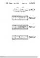
- FIGS. 10, 11, and 12are diagrammatic representations of the electrical breakdown mechanism employed in the invention.
- FIG. 13is a schematic diagram of electronic apparatus for determining the resonant frequency of a tag circuit to be deactivated
- FIGS. 14 and 15are waveforms useful in illustrating the operation of the apparatus of FIG. 13.
- FIG. 16is a block diagram of an electronic deactivator providing deactivation energy for a controlled interval.
- a resonant tag circuitwhich includes a capacitor C1 formed of capacitor plates 10 and 12 on respective opposite surfaces of a substrate 14 which is of a dielectric or electrically insulative material, and an inductor L1 in series with the capacitor to provide a single resonant frequency.
- the inductoris connected at one end to capacitor plate 10, and has the other end connected to an electrical path 16 through the substrate 14 which is connected to the capacitor plate 12 via a conductive path 18.
- the inductor and capacitor plate 10are integrally formed on one surface of the substrate.
- the inductoris formed as a flat, rectangular spiral on the substrate surface.
- the capacitor plate 12 and associated connecting pathare integrally formed on the opposite substrate surface.
- a portion 20 of the conductive path 18 which confronts the capacitor plate 10is indented or otherwise formed to be spaced from the capacitor plate 10 by a distance which is less than the distance between the plates 10 and 12.
- the voltage across the capacitor plates 10 and 12increases until electrical breakdown occurs at the burnout provided by the indented portion 20 of the conductive path. Since this portion provides the shortest distance between the capacitor plates, electrical breakdown always occurs at this point.
- the electric arc formed at breakdownis sustained by the energy which is being continuously coupled to the resonant circuit by an external power source. The electric arc vaporizes metal in the vicinity of the breakdown region 20 which destroys the conductive path 18, thereby permanently destroying the resonant characteristics of the tag circuit.
- FIG. 2An alternative embodiment of the resonant tag circuit is illustrated schematically in FIG. 2 in which the tag circuit exhibits two resonant frequencies.
- the circuit of FIG. 2includes a second capacitor C2 formed by plates 22 and 24 and an inductor L2.
- the junction of the inductors L1 and L2is connected to the capacitor plate 22.
- the other end of inductor L2is connected to a through connection 26 in the substrate and which is connected through a conductive path 28 to the capacitor plate 24.
- a conductive path 30interconnects the capacitor plates 24 and 12, and this conductive path includes an indented burnout portion 32 provided in confronting relation to the capacitor plate 22.
- One resonant frequencyis employed for detection of the tag by an associated electronic security system, and the other resonant frequency is employed for deactivation of the tag.
- the deactivation frequencyis selected to be one of the frequencies allocated by the Federal Communications Commission (FCC) to be in the industrial, scientific and medical (ISM) band so that the radiated energy for tag deactivation can be at relatively high power without special federal license.
- the detection frequencyis usually chosen to be in one of the frequency bands allocated for field disturbance sensors. A detection frequency of 8.2 MHz is typical.
- the capacitor C2 and inductor L2are the primary components which form a resonant tunned circuit at the deactivation frequency, while the inductor L1 in conjunction with the capacitor C1 are the primary components which form a resonant tuned circuit at the detection frequency. Due to mutual coupling, all the components interact to provide the exact detection and deactivation frequencies. When sufficient energy is coupled to the circuit at the deactivation frequency, the voltage increases across the capacitor plates 22 and 24 until the substrate film breaks down at the burnout point 32. Again, breakdown always occurs at the burnout point, since this point or region 32 provides the shortest distance between the capacitor plates 22 and 24.
- the electric arc provided upon breakdownis sustained by the energy being coupled to the resonant circuit from the external power source and this arc causes vaporization of metal in the vicinity of the breakdown region, including the adjacent portion of conductive path 30.
- the electric arcis extinguished.
- the resonant properties of the tag at the detection frequencyare permanently destroyed since there is no longer an electrical connection between capacitor plate 24 and capacitor plate 12.
- the resonant circuits of FIGS. 1 and 2do not require the use of a small narrow fuse and there is thus no additional resistance placed in series with the inductor and capacitor elements of the circuit. There is, therefore, no degradation of the Q of the resonant circuit. Moreover, since the electric arc occurs between the capacitor plates and not on the surface, the materials which cover or are in contact with the surface of the capacitor plates do not significantly affect the ability of the electric arc to vaporize the metal in the vicinity of the arc. In order to maximize the voltage developed across the capacitor plates 22 and 24, the capacitance of capacitor C2 should be as small as possible and the inductance of inductor L2 should be as large as possible to provide resonance at the intended deactivation frequency. The capacitor C2 can be made quite small physically and will not significantly increase the overall size and cost of the dual frequency tag circuit of FIG. 2.
- the resonant tag circuit of FIG. 1is illustrated in typical construction in FIGS. 3 and 4 which respectively depict the opposite planar surfaces of the tag.
- the inductor L1is formed as a flat spiral 40 on the surface of the thin plastic film substrate 42.
- the plastic filmserves as the dielectric of the parallel plate capacitor as well as the supporting substrate for the circuit.
- the spiral pathextends between an outer conductive area 44 and an inner conductive area 46.
- the inner conductive area 46serves as capacitor plate 10.
- conductive areas 48 and 50are in alignment with the respective conductive areas 44 and 46, and are interconnected by a conductive path 52.
- the conductive area 50serves as the capacitor plate 12 and thus capacitor C1 is provided by the confronting conductive areas 46 and 50.
- a conductive interconnection 54couples conductive areas 44 and 48 together to complete the circuit.
- the conductive area 50includes recesses 51 adjacent to the area of joinder between the conductive area 50 and the conductive path 52.
- This areaincludes an indented portion 56 to provide a conductive area of the path 52 which confronts the conductive area 46 and which is more closely spaced thereto than the spacing between the conductive areas 46 and 50.
- This indentation 56provides the burnout point at which electrical breakdown will occur in response to the application of energy from an external source at the resonant frequency of the tag circuit and of sufficient power to cause breakdown.
- the dual frequency tag circuit of FIG. 2is shown in typical construction in FIGS. 5 and 6 which depict the respective opposite planar surfaces of the tag.
- the inductor L1is formed by a flat spiral 60 on the surface of the plastic film 62, this spiral extending between conductive areas 64 and 66.
- the conductor L2is formed by a flat spiral 68 on the film surface and which extends between conductive area 64 and conductive area 70.
- conductive areas 72, 74, and 76are provided in alignment with the respective conductive areas 64, 66, and 70 on the other substrate surface.
- the conductive areas 72 and 74are interconnected by a conductive path 78, while the conductive areas 72 and 76 are connected by a conductive path 80.
- a burnout pointis provided in the conductive path 78 by indentation of a portion 82 of the path confronting the conductive area 64.
- the capacitor C1 of FIG. 2is provided by the conductive areas 66 and 74, while the capacitor C2 is provided by the conductive areas 64 and 72.
- a conductive interconnection 84 between the conductive areas 70 and 76is provided through the substrate film to complete the circuit. The circuit is operative in the manner described to cause destruction of the resonant properties of the tag circuit at the detection frequency by burnout or vaporization of the conductive path near the burnout point 82 in response to an electric arc.
- the resonant tags described hereinare similar to those of U.S. Pat. No. 3,810,147 of the inventor hereof. Construction of the tag circuits is preferably according to the planar circuit fabrication process which is the subject of U.S. Pat. No. 3,913,219 of the inventor hereof.
- FIG. 7Apparatus is shown in FIG. 7 for use in deactivating the resonant properties of the tag circuits described above.
- This apparatusincludes an antenna 90 operative to sense the presence of a resonant tag circuit 92 and coupled to a tag sensing system 94 which provides an output signal to a tag presence indicator 96 and a tag deactivation indicator 98.
- the tag sensing system 94also provides a control signal to a tag deactivation system 100 which includes an antenna 102.
- the tag deactivation systemcan also be manually activated by manual control 104.
- the tag sensing system 94Upon sensing the presence of the tag circuit 92, the tag sensing system 94 is operative to trigger the deactivation system 100 to cause radiation by antenna 102 of radiation at the resonant frequency of the tag circuit and of sufficient power level to cause electrical breakdown at the breakdown point of the tag circuit and formation of an electric arc.
- the deactivation systemprovides energy at the deactivation frequency of that tag. Visual or other indications can be provided by indicators 96 and 98 of the presence and deactivation of the tag.
- a tag circuitis a single resonant circuit as shown in FIG. 1, the tag sensing system 94 is operative to determine the resonant frequency of the particular tag 92 which is sensed, and to provide a control signal to the deactivation system 100 representative of the measured resonant tag frequency. In response to the control signal, the deactivation system will provide radiation at this resonant frequency, and efficient coupling to the tag circuit for destruction of its resonant properties.
- the tag sensing system 94can include the apparatus shown in FIG. 13 to determine the approximate resonant frequency of the tag circuit.
- a voltage controlled oscillator 150drives the tag sensing antenna 90, the oscillator being controlled by the output of a microcomputer 152 by way of a digital-to-analog converter 154.
- the microcomputerstores digital values which after conversion to analog form by converter 154, drive oscillator 150 to produce a stepwise frequency sweep.
- the antenna signalis applied to an analog-to-digital converter 156, the digital output of which is applied to the microcomputer 152 which stores such outputs.
- FIG. 14illustrates the output of the voltage controlled oscillator 150 in relation to time.
- FIG. 15illustrates the current through the antenna 90 in relation to time.
- the current through the antennadecreases as the frequency of the oscillator increases, as illustrated by the straight line portion of the waveform of FIG. 15.
- the impedance of the resonant circuitwill be reflected into the antenna and cause an abrupt reduction in antenna current as illustrated in FIG. 15.
- the current through the antennais converted to digital values by converter 156, and these digital values are stored in the memory of microcomputer 152.
- the step number which corresponds to the minimum value of the stored current valuescorresponds to the approximate resonant frequency of the tag circuit.
- the stored digital value representing the resonant frequencyis converted to an analog signal for control of oscillator 150 to provide an output at the resonant frequency for actuation of deactivation system 100 (FIG. 7) for destruction of the resonant properties of the tag circuit 92.
- the deactivation energyis applied for a predetermined period of time determined in accordance with the time intended for tag deactivation.
- the tag sensing system 94is operative to sense tag presence, and if the tag has been deactivated, the indicator 98 will be energized to denote that deactivation has occurred. If the tag 92 is still operative at its resonant frequency as sensed by system 94, the deactivation system 100 will again be triggered for another deactivation cycle. The deactivation cycle will be repeated a predetermined number of times until deactivation occurs. If deactivation has not occurred after a predetermined number of cycles, an annunciator can be enabled to denote to the operator that the particular tag has not been deactivated. The operator can then manually actuate the deactivation system for deactivation of the tag or take other action to deactivate or destroy the tag.
- the tag sensing system 94upon detection of a resonant tag circuit 92, can cause the deactivation system 100 to drive antenna 102 with a relatively high power signal that is slowly swept in frequency through the resonant frequency of the tag 92.
- the apparatuscan be operative to alternately sense tag presence and activate the deactivation field in a cyclic manner until the tag is deactivated. Again, an operator can be notified by appropriate annunciation in the event that a particular tag has not been deactivated.
- the tag sensing system 94is operative to detect the resonant detection frequency of the tag, while the deactivation system 100 is operative to provide energy at the resonant deactivation frequency of the tag.
- Apparatus suitable for deactivation and sensing of the two frequency tagis described in patent 3,938,044 of the same inventor as herein.
- FIGS. 8 and 9Resonant circuits of alternative construction are shown in FIGS. 8 and 9 and which will be recognized as being similr to the respective circuits of FIGS. 1 and 2.
- an indentationis made at any selected point or multiple points on one or both of the capacitor plates to reduce the thickness of the dielectric film at this indentation, and thereby reduce the voltage required to cause an arc across the capacitor plates.
- the indentationis shown in the capacitor plate 12a.
- the indentationis shown in the capacitor plate 24a.
- FIGS. 10-12The deactivation sequence is illustrated in FIGS. 10-12.
- FIG. 10there is shown the commencement of a voltage breakdown through the plastic film 110 and between the plates 112 and 114. Formation of the plasma after arc discharge is shown in FIG. 11, and the final deposition of metal along the discharge path to short circuit the capacitor plates is depicted in FIG. 12.
- the deactivation powershould be accurately controlled, or the deactivation process electronically monitored to turn off the deactivator shortly after the first arc has formed.
- the deactivatorcan be re-energized on a cyclic basis as described until a permanent short circuit has developed across the capacitor plates. Since the deactivator antenna is coupled to the tag circuit, the impedance of the tag circuit is reflected back into the deactivation antenna.
- the impedance of the resonant circuitabruptly changes, and this change is reflected directly back into the deactivation antenna and can be detected by the deactivation system and employed for accurate control of the deactivation system.
- the deactivation systemcan be turned off and cyclically reapplied to cause arc formation and deposition of metal along the discharge path between the capacitor plates to provide in a controlled manner deactivation of the resonant properties of the tag circuit.
- the deactivation system 100can be controlled in the manner illustrated in FIG. 16.
- the tag sensing system 94provides a tag signal in response to the swept radio frequency signal passing through the resonant frequency of the tag circuit, and this tag signal is applied to a sharp cutoff high pass filter 160.
- the filter 160filters out the modulation components and substantially all components of the tag signal spectrum.
- a threshold detector 162which triggers a timer 164 which determines the time interval during which the tag deactivation system 100 operates.
- the operating cyclemay be repeated as necessary to deactivate the resonant properties of the tag circuit.
Landscapes
- Physics & Mathematics (AREA)
- Engineering & Computer Science (AREA)
- Automation & Control Theory (AREA)
- Computer Security & Cryptography (AREA)
- Electromagnetism (AREA)
- General Physics & Mathematics (AREA)
- Burglar Alarm Systems (AREA)
Abstract
Description
Claims (25)
Priority Applications (10)
| Application Number | Priority Date | Filing Date | Title |
|---|---|---|---|
| US06/376,777US4498076A (en) | 1982-05-10 | 1982-05-10 | Resonant tag and deactivator for use in an electronic security system |
| NL8420106ANL193507C (en) | 1982-05-10 | 1984-04-23 | Electronically detectable and deactivatable label circuit for use in an electronic surveillance system. |
| CH387288ACH673722C1 (en) | 1982-05-10 | 1984-04-23 | Resonant tag and deactivator for elrctronic security system |
| GB08531530AGB2173073B (en) | 1982-05-10 | 1984-04-23 | Resonant tag and deactivator for use in an electronic security system |
| CH1586ACH669858C2 (en) | 1982-05-10 | 1984-04-23 | |
| PCT/US1984/000613WO1985004975A1 (en) | 1982-05-10 | 1984-04-23 | Resonant tag and deactivator for use in an electronic security system |
| EP84901894AEP0181327B2 (en) | 1982-05-10 | 1984-04-23 | Resonant tag and deactivator for use in an electronic security system |
| IN485/CAL/84AIN163532B (en) | 1982-05-10 | 1984-07-07 | |
| US06/673,265US4567473A (en) | 1982-05-10 | 1984-11-20 | Resonant tag and deactivator for use in an electronic security system |
| SE8505999ASE460809B (en) | 1982-05-10 | 1985-12-18 | RESONANT LABEL CIRCUIT INCLUDING MONEY TO ENSURE ITS RESONANT PROPERTIES AND SECURITY SYSTEM PROVIDED FOR SUCH LABEL CIRCUIT |
Applications Claiming Priority (3)
| Application Number | Priority Date | Filing Date | Title |
|---|---|---|---|
| US06/376,777US4498076A (en) | 1982-05-10 | 1982-05-10 | Resonant tag and deactivator for use in an electronic security system |
| PCT/US1984/000613WO1985004975A1 (en) | 1982-05-10 | 1984-04-23 | Resonant tag and deactivator for use in an electronic security system |
| US06/673,265US4567473A (en) | 1982-05-10 | 1984-11-20 | Resonant tag and deactivator for use in an electronic security system |
Related Child Applications (1)
| Application Number | Title | Priority Date | Filing Date |
|---|---|---|---|
| US06/673,265ContinuationUS4567473A (en) | 1982-05-10 | 1984-11-20 | Resonant tag and deactivator for use in an electronic security system |
Publications (1)
| Publication Number | Publication Date |
|---|---|
| US4498076Atrue US4498076A (en) | 1985-02-05 |
Family
ID=27374678
Family Applications (2)
| Application Number | Title | Priority Date | Filing Date |
|---|---|---|---|
| US06/376,777Expired - LifetimeUS4498076A (en) | 1982-05-10 | 1982-05-10 | Resonant tag and deactivator for use in an electronic security system |
| US06/673,265Expired - LifetimeUS4567473A (en) | 1982-05-10 | 1984-11-20 | Resonant tag and deactivator for use in an electronic security system |
Family Applications After (1)
| Application Number | Title | Priority Date | Filing Date |
|---|---|---|---|
| US06/673,265Expired - LifetimeUS4567473A (en) | 1982-05-10 | 1984-11-20 | Resonant tag and deactivator for use in an electronic security system |
Country Status (7)
| Country | Link |
|---|---|
| US (2) | US4498076A (en) |
| EP (1) | EP0181327B2 (en) |
| CH (1) | CH669858C2 (en) |
| GB (1) | GB2173073B (en) |
| NL (1) | NL193507C (en) |
| SE (1) | SE460809B (en) |
| WO (1) | WO1985004975A1 (en) |
Cited By (100)
| Publication number | Priority date | Publication date | Assignee | Title |
|---|---|---|---|---|
| WO1986005302A1 (en)* | 1985-03-08 | 1986-09-12 | Reeb Max E | A label-like device and process for its manufacture |
| US4673932A (en)* | 1983-12-29 | 1987-06-16 | Revlon, Inc. | Rapid inventory data acquistion system |
| WO1987004283A1 (en)* | 1986-01-10 | 1987-07-16 | Checkpoint Systems, Inc. | Security tag deactivation system |
| US4689636A (en)* | 1985-03-15 | 1987-08-25 | Minnesota Mining And Manufacturing Company | Deactivatable resonant marker for use in RF electronic article surveillance system |
| US4779077A (en)* | 1987-04-13 | 1988-10-18 | Lichtblau G J | Continuously armed high reliability pulse train processor |
| US4862160A (en)* | 1983-12-29 | 1989-08-29 | Revlon, Inc. | Item identification tag for rapid inventory data acquisition system |
| WO1990003623A1 (en)* | 1988-09-30 | 1990-04-05 | Scientific Generics Limited | System for verification of de-activation of anti-theft markers |
| US4970495A (en)* | 1987-11-14 | 1990-11-13 | Tokai Metals Co., Ltd. | Resonant frequency characteristic tag and method of manufacturing the same |
| US4985288A (en)* | 1988-04-30 | 1991-01-15 | Tokai Metals Co., Ltd. | Resonant frequency characteristic tag and method of manufacturing the same |
| GB2234885A (en)* | 1986-09-29 | 1991-02-13 | Monarch Marking Systems Inc | Deactivatable tags for use in electronic article surveillance systems and methods of making them |
| US5012225A (en)* | 1989-12-15 | 1991-04-30 | Checkpoint Systems, Inc. | System for deactivating a field-sensitive tag or label |
| US5059951A (en)* | 1988-11-14 | 1991-10-22 | Checkpoint Systems, Inc. | Method and apparatus for integrated data capture and electronic article surveillance |
| US5081445A (en)* | 1991-03-22 | 1992-01-14 | Checkpoint Systems, Inc. | Method for tagging articles used in conjunction with an electronic article surveillance system, and tags or labels useful in connection therewith |
| EP0541544A4 (en)* | 1989-10-31 | 1992-03-18 | Checkpoint Systems Inc | Method for tagging articles used in conjunction with an electronic article surveillance system, and tags or labels useful in connection therewith. |
| US5103210A (en)* | 1990-06-27 | 1992-04-07 | Checkpoint Systems, Inc. | Activatable/deactivatable security tag for use with an electronic security system |
| FR2669756A1 (en)* | 1990-11-23 | 1992-05-29 | Cga Hbs | System for recording and invalidating the identification of a product |
| US5142270A (en)* | 1991-05-22 | 1992-08-25 | Checkpoint Systems Inc. | Stabilized resonant tag circuit and deactivator |
| US5142292A (en)* | 1991-08-05 | 1992-08-25 | Checkpoint Systems, Inc. | Coplanar multiple loop antenna for electronic article surveillance systems |
| WO1993005486A1 (en)* | 1991-09-09 | 1993-03-18 | Checkpoint Systems, Inc. | Binary encoded multiple frequency rf identification tag |
| WO1993008548A1 (en)* | 1991-10-23 | 1993-04-29 | Checkpoint Systems, Inc. | Security tag with electrostatic protection |
| US5241299A (en)* | 1991-05-22 | 1993-08-31 | Checkpoint Systems, Inc. | Stabilized resonant tag circuit |
| US5254974A (en)* | 1990-09-28 | 1993-10-19 | N.V. Nederlandsche Apparatenfabriek Nedap | Deactivating device |
| US5276431A (en)* | 1992-04-29 | 1994-01-04 | Checkpoint Systems, Inc. | Security tag for use with article having inherent capacitance |
| US5341125A (en)* | 1992-01-15 | 1994-08-23 | Sensormatic Electronics Corporation | Deactivating device for deactivating EAS dual status magnetic tags |
| US5447779A (en)* | 1990-08-06 | 1995-09-05 | Tokai Electronics Co., Ltd. | Resonant tag and method of manufacturing the same |
| EP0698870A1 (en) | 1994-08-25 | 1996-02-28 | Toyo Aluminium Kabushiki Kaisha | Resonant sensor |
| US5510770A (en)* | 1994-03-30 | 1996-04-23 | Checkpoint Systems, Inc. | Surface deactivateable tag |
| US5589820A (en)* | 1993-10-05 | 1996-12-31 | Pac/Scan, Inc. | Retail theft prevention and information device |
| US5589251A (en)* | 1990-08-06 | 1996-12-31 | Tokai Electronics Co., Ltd. | Resonant tag and method of manufacturing the same |
| US5650596A (en)* | 1994-08-05 | 1997-07-22 | Surgical Resources, L.L.C. | Automatic surgical sponge counter and blood loss determination system |
| NL1002720C2 (en)* | 1996-03-27 | 1997-09-30 | Nedap Nv | Fixed frequency resonance label for theft prevention |
| US5689263A (en)* | 1991-07-09 | 1997-11-18 | Esselte Meto International Gmbh | Antipilferage markers |
| US5695860A (en)* | 1990-08-06 | 1997-12-09 | Tokai Electronics Co., Ltd. | Resonant tag and method of manufacturing the same |
| DE19705723A1 (en)* | 1996-08-06 | 1998-02-12 | Esselte Meto Int Gmbh | Securing element for electronic article surveillance |
| WO1998006074A1 (en)* | 1996-08-06 | 1998-02-12 | Meto International Gmbh | Resonant circuit for electronic anti-theft element |
| WO1998006075A1 (en)* | 1996-08-06 | 1998-02-12 | Meto International Gmbh | Electronic anti-theft element |
| US5756986A (en)* | 1993-04-14 | 1998-05-26 | Gustafson; Ake | Electronic marking device for recognition of a piece of textile |
| US5786764A (en)* | 1995-06-07 | 1998-07-28 | Engellenner; Thomas J. | Voice activated electronic locating systems |
| US5841350A (en)* | 1997-06-27 | 1998-11-24 | Checkpoint Systems, Inc. | Electronic security tag useful in electronic article indentification and surveillance system |
| US5852856A (en)* | 1997-11-13 | 1998-12-29 | Seidel; Stuart T. | Anti theft ink tag |
| US5861809A (en)* | 1997-09-22 | 1999-01-19 | Checkpoint Systems, Inc. | Deactivateable resonant circuit |
| DE19749213A1 (en)* | 1997-11-07 | 1999-05-12 | Rehder Physik Gmbh | Goods security label which can be switched on and off |
| US5923001A (en)* | 1994-08-05 | 1999-07-13 | Surgical Resources, L.L.C. | Automatic surgical sponge counter and blood loss determination system |
| US5973606A (en)* | 1997-12-08 | 1999-10-26 | Sensormatic Electronics Corporation | Activation/deactivation system and method for electronic article surveillance markers for use on a conveyor |
| US6050622A (en)* | 1991-12-19 | 2000-04-18 | Gustafson; Ake | Safety sealing device |
| US6091607A (en)* | 1998-12-10 | 2000-07-18 | Checkpoint Systems, Inc. | Resonant tag with a conductive composition closing an electrical circuit |
| USD452220S1 (en) | 1998-10-15 | 2001-12-18 | Meto International Gmbh | Arrangement of aluminum foil coils forming an inductor of a resonant frequency identification element |
| US6404340B1 (en) | 2000-06-19 | 2002-06-11 | Massachusetts Institute Of Technology | Multiple-axis tracking of passive resonant structures |
| US20020171498A1 (en)* | 2001-05-16 | 2002-11-21 | Leenaerts Dominicus Martinus Wilhelmus | Method for modulating an output voltage of a RF transmitter circuit, and RF transmitter circuit |
| JP3406132B2 (en) | 1995-07-17 | 2003-05-12 | チェックポイント・マニュファクチュアリング・ジャパン株式会社 | Method of manufacturing resonance tag and resonance tag |
| US20030169153A1 (en)* | 2000-03-28 | 2003-09-11 | Philipp Muller | Rfid-label with an element for regulating the resonance frequency |
| US20030187021A1 (en)* | 2001-10-16 | 2003-10-02 | Hypnion, Inc. | Treatment of CNS disorders using CNS target modulators |
| WO2003091962A1 (en)* | 2002-04-25 | 2003-11-06 | Upm Rafsec Oy | A method for maufacturing a product sensor, and a product sensor |
| US20040031626A1 (en)* | 1994-08-05 | 2004-02-19 | Morris Sharon L. | Automatic surgical sponge counter and blood loss determination system |
| US20040075607A1 (en)* | 2000-04-26 | 2004-04-22 | Cathey David A. | Automated antenna trim for transmitting and receiving semiconductor devices |
| WO2002091322A3 (en)* | 2001-05-04 | 2004-06-03 | Micrometal Technologies Inc | Metalized dielectric substrates for eas tags |
| US20050129842A1 (en)* | 2002-05-02 | 2005-06-16 | Burke Thomas F. | Metalized dielectric substrates for EAS tags |
| KR100492042B1 (en)* | 1996-03-07 | 2005-08-23 | 체크포인트 시스템즈 인코포레이티드 | Security tag and manufacturing method |
| US20050183264A1 (en)* | 2004-02-23 | 2005-08-25 | Eric Eckstein | Method for aligning capacitor plates in a security tag and a capacitor formed thereby |
| US20050183817A1 (en)* | 2004-02-23 | 2005-08-25 | Eric Eckstein | Security tag system for fabricating a tag including an integrated surface processing system |
| US20050184873A1 (en)* | 2004-02-23 | 2005-08-25 | Eric Eckstein | Tag having patterned circuit elements and a process for making same |
| US20050184872A1 (en)* | 2004-02-23 | 2005-08-25 | Clare Thomas J. | Identification marking and method for applying the identification marking to an item |
| US20050201450A1 (en)* | 2004-03-03 | 2005-09-15 | Volpi John P. | Interrogator and interrogation system employing the same |
| US6946963B2 (en) | 2001-10-16 | 2005-09-20 | Spectra Research, Inc. | Secure storage disc and disc surveillance system |
| US20060017545A1 (en)* | 2004-03-26 | 2006-01-26 | Volpi John P | Radio frequency identification interrogation systems and methods of operating the same |
| US20060049947A1 (en)* | 2004-09-09 | 2006-03-09 | Forster Ian J | RFID tags with EAS deactivation ability |
| US20060077036A1 (en)* | 2004-09-29 | 2006-04-13 | Roemerman Steven D | Interrogation system employing prior knowledge about an object to discern an identity thereof |
| US20060202827A1 (en)* | 2003-03-03 | 2006-09-14 | Volpi John P | Interrogator and interrogation system employing the same |
| US7152804B1 (en) | 2004-03-15 | 2006-12-26 | Kovlo, Inc. | MOS electronic article surveillance, RF and/or RF identification tag/device, and methods for making and using the same |
| US20070012775A1 (en)* | 2004-02-23 | 2007-01-18 | Checkpoint Systems, Inc. | Method of fabricating a security tag in an integrated surface processing system |
| US20070018828A1 (en)* | 2001-05-31 | 2007-01-25 | Alien Technology Corp. | System and method for disabling data on radio frequency identification tags |
| US20070075837A1 (en)* | 1996-07-30 | 2007-04-05 | Tuttle Mark E | Radio frequency data communications device with selectively removable antenna portion and method |
| US20070096852A1 (en)* | 2005-06-25 | 2007-05-03 | Qinetiq Limited | Electromagnetic radiation decoupler |
| US7286053B1 (en) | 2004-07-31 | 2007-10-23 | Kovio, Inc. | Electronic article surveillance (EAS) tag/device with coplanar and/or multiple coil circuits, an EAS tag/device with two or more memory bits, and methods for tuning the resonant frequency of an RLC EAS tag/device |
| US20070290941A1 (en)* | 2006-06-16 | 2007-12-20 | Qinetiq Limited | Electromagnetic Enhancement and Decoupling |
| US20080018469A1 (en)* | 2003-03-03 | 2008-01-24 | Volpi John P | Interrogator and Interrogation System Employing the Same |
| US20080018450A1 (en)* | 2003-03-03 | 2008-01-24 | Volpi John P | Interrogator and Interrogation System Employing the Same |
| US20080018468A1 (en)* | 2003-03-03 | 2008-01-24 | Volpi John P | Interrogator and Interrogation System Employing the Same |
| US20080018432A1 (en)* | 2003-03-03 | 2008-01-24 | Volpi John P | Interrogator and Interrogation System Employing the Same |
| US20080024277A1 (en)* | 2003-03-03 | 2008-01-31 | Volpi John P | Interrogator and Interrogation System Employing the Same |
| US20080024276A1 (en)* | 2003-03-03 | 2008-01-31 | Volpi John P | Interrogator and Interrogation System Employing the Same |
| US20080197981A1 (en)* | 2001-05-31 | 2008-08-21 | Stewart Roger G | Integrated circuits with persistent data storage |
| US20080237341A1 (en)* | 2006-09-13 | 2008-10-02 | Clearcount Medical Solutions, Inc. | Apparatus and methods for monitoring objects in a surgical field |
| US20090045917A1 (en)* | 2007-08-13 | 2009-02-19 | Volpi John P | Interrogator and Interrogation System Employing the Same |
| US20090140860A1 (en)* | 2007-12-03 | 2009-06-04 | Forster Ian J | Dual use rfid/eas device |
| US20100045025A1 (en)* | 2008-08-20 | 2010-02-25 | Omni-Id Limited | One and Two-Part Printable EM Tags |
| US7737825B1 (en) | 2001-05-31 | 2010-06-15 | Alien Technology Corporation | Integrated circuits with persistent data storage |
| US20100230497A1 (en)* | 2006-12-20 | 2010-09-16 | Omni-Id Limited | Radiation Enhancement and Decoupling |
| US20110037541A1 (en)* | 2006-12-14 | 2011-02-17 | Omni-Id Limited | Switchable Radiation Enhancement and Decoupling |
| US8099335B2 (en) | 2004-02-23 | 2012-01-17 | Checkpoint Systems, Inc. | Method and system for determining billing information in a tag fabrication process |
| US8138921B1 (en)* | 2007-08-09 | 2012-03-20 | Kovio, Inc. | Reliable tag deactivation |
| US20120176226A1 (en)* | 2004-10-08 | 2012-07-12 | Mackenzie J Devin | RF and/or RF Identification Tag/Device Having an Integrated Interposer, and Methods for Making and Using the Same |
| CN101551873B (en)* | 2008-04-03 | 2013-07-10 | 北京顺特科技有限公司 | Friction type resurrection-resistant radio frequency theftproof label |
| US8542717B2 (en) | 2003-03-03 | 2013-09-24 | Veroscan, Inc. | Interrogator and interrogation system employing the same |
| US20140207660A1 (en)* | 2013-01-24 | 2014-07-24 | Nxp B.V. | Tag System, Sellable Item and Method for Facilitating the Purchase of a Sellable Item |
| US20140292610A1 (en)* | 2013-03-29 | 2014-10-02 | Sony Corporation | Non-contact communication antenna, communication device, and method for manufacturing non-contact communication antenna |
| US8912890B2 (en) | 2012-10-01 | 2014-12-16 | Thin Film Electronics Asa | Surveillance devices with multiple capacitors |
| US9035774B2 (en) | 2011-04-11 | 2015-05-19 | Lone Star Ip Holdings, Lp | Interrogator and system employing the same |
| US20240113563A1 (en)* | 2018-03-02 | 2024-04-04 | Auckland Uniservices Limited | Wireless power transfer device |
| USD1051399S1 (en) | 2021-02-26 | 2024-11-12 | Stryker Corporation | Reader cradle for a surgical stand |
Families Citing this family (53)
| Publication number | Priority date | Publication date | Assignee | Title |
|---|---|---|---|---|
| US4736207A (en)* | 1986-01-31 | 1988-04-05 | Sensormatic Electronics Corporation | Tag device and method for electronic article surveillance |
| US4954814A (en)* | 1986-09-29 | 1990-09-04 | Monarch Marking Systems, Inc. | Tag and method of making same |
| CA1294117C (en)* | 1986-09-29 | 1992-01-14 | S. Eugene Benge | Method of making deactivatable tags |
| US4717438A (en)* | 1986-09-29 | 1988-01-05 | Monarch Marking Systems, Inc. | Method of making tags |
| US4846922A (en)* | 1986-09-29 | 1989-07-11 | Monarch Marking Systems, Inc. | Method of making deactivatable tags |
| US4778552A (en)* | 1986-09-29 | 1988-10-18 | Monarch Marking Systems, Inc. | Alarm tag and method of making and deactivating it |
| US4802944A (en)* | 1986-09-29 | 1989-02-07 | Monarch Marking Systems, Inc. | Method of making deactivatable tags |
| DE3878717D1 (en)* | 1987-04-23 | 1993-04-08 | Actron Entwicklungs Ag | METHOD FOR DEACTIVATING A RESON LABEL AND CIRCUIT FOR IMPLEMENTING THE METHOD. |
| US4835524A (en)* | 1987-12-17 | 1989-05-30 | Checkpoint System, Inc. | Deactivatable security tag |
| US4920335A (en)* | 1989-01-31 | 1990-04-24 | Interamerican Industrial Company | Electronic article surveillance device with remote deactivation |
| JP2533800B2 (en)* | 1989-06-02 | 1996-09-11 | 山武ハネウエル株式会社 | Microwave response device |
| US5006856A (en)* | 1989-08-23 | 1991-04-09 | Monarch Marking Systems, Inc. | Electronic article surveillance tag and method of deactivating tags |
| US5367290A (en)* | 1989-12-20 | 1994-11-22 | Actron Entwicklungs Ag | Deactivatable resonance label |
| US5027106A (en)* | 1989-12-27 | 1991-06-25 | Checkpoint Systems, Inc. | Method and apparatus for electronic article surveillance |
| NL9000186A (en)* | 1990-01-25 | 1991-08-16 | Nedap Nv | DEACTIVATOR. |
| US5025246A (en)* | 1990-04-10 | 1991-06-18 | Sensormatic Electronics Corporation | EAS tag with motion detection facility |
| DE59108459D1 (en)* | 1990-04-25 | 1997-02-20 | Actron Entwicklungs Ag | Method for deactivating a resonance tag and circuit arrangement for carrying out the method |
| US5257010A (en)* | 1990-04-25 | 1993-10-26 | Actron Entwicklungs | Process for the deactivation of a reasonance label and circuit arrangement for the execution of the process |
| US5059950A (en)* | 1990-09-04 | 1991-10-22 | Monarch Marking Systems, Inc. | Deactivatable electronic article surveillance tags, tag webs and method of making tag webs |
| US5081446A (en)* | 1990-09-24 | 1992-01-14 | Checkpoint Systems, Inc. | Security tag for compact disc storage container |
| US5442334A (en)* | 1992-07-20 | 1995-08-15 | Stoplift Corporation | Security system having deactivatable security tag |
| NL9202067A (en)* | 1992-11-27 | 1994-06-16 | Dutch A & A Trading Bv | Detection label. |
| DE4244272A1 (en)* | 1992-12-28 | 1994-06-30 | Daimler Benz Ag | Field effect controlled semiconductor device |
| NL9400810A (en)* | 1994-05-18 | 1996-01-02 | Nedap Nv | Deactivation and coding system for a contactless anti-theft or identification label. |
| US5517195A (en)* | 1994-09-14 | 1996-05-14 | Sensormatic Electronics Corporation | Dual frequency EAS tag with deactivation coil |
| US5541399A (en)* | 1994-09-30 | 1996-07-30 | Palomar Technologies Corporation | RF transponder with resonant crossover antenna coil |
| DE4435815A1 (en)* | 1994-10-07 | 1996-04-11 | Esselte Meto Int Gmbh | Label with covering layer carrying information e.g. for stockroom or store |
| DE4442510A1 (en) | 1994-11-30 | 1996-06-05 | Esselte Meto Int Gmbh | Label to secure an article against theft |
| US5508684A (en)* | 1995-03-02 | 1996-04-16 | Becker; Richard S. | Article tag |
| FI100491B (en)* | 1995-08-23 | 1997-12-15 | Tuotesuoja Sirpa Jaervensivu K | Deactivator for a product protection sensor |
| US5574431A (en)* | 1995-08-29 | 1996-11-12 | Checkpoint Systems, Inc. | Deactivateable security tag |
| SE510118C2 (en)* | 1996-04-11 | 1999-04-19 | Leif Goesta Aasbrink | Method and apparatus for deactivating alarm elements |
| US5781110A (en)* | 1996-05-01 | 1998-07-14 | James River Paper Company, Inc. | Electronic article surveillance tag product and method of manufacturing same |
| DE19753619A1 (en)* | 1997-10-29 | 1999-05-06 | Meto International Gmbh | Identification tag with radio frequency identification transponder |
| US5963134A (en) | 1997-07-24 | 1999-10-05 | Checkpoint Systems, Inc. | Inventory system using articles with RFID tags |
| US6025780A (en)* | 1997-07-25 | 2000-02-15 | Checkpoint Systems, Inc. | RFID tags which are virtually activated and/or deactivated and apparatus and methods of using same in an electronic security system |
| DE19908877A1 (en)* | 1999-03-01 | 2000-10-12 | Georg Siegel Gmbh Zur Verwertu | Goods security label for LF operation has flat carrier element with defined number of tracks of electrically conducting material applied to one surface parallel to each other to form spiral path |
| US6232878B1 (en) | 1999-05-20 | 2001-05-15 | Checkpoint Systems, Inc. | Resonant circuit detection, measurement and deactivation system employing a numerically controlled oscillator |
| ES2220565T3 (en)* | 1999-12-07 | 2004-12-16 | Datamars Sa | PROCEDURE FOR THE OPERATION OF A TRANSPONDER. |
| UA59498C2 (en)* | 1999-12-07 | 2003-09-15 | Інфінеон Текнолоджіс Аг | Goods label, a method for producing the label, and a method for contactless identification of goods |
| WO2001099074A2 (en)* | 2000-06-19 | 2001-12-27 | Impac Group, Inc. | Electronic article surveillance tag and method for making same |
| US6595421B2 (en) | 2001-01-31 | 2003-07-22 | Ncr Corporation | Integrated antenna scanner window |
| US6919806B2 (en)* | 2002-09-06 | 2005-07-19 | Sensormatic Electronics Corporation | Deactivatable radio frequency security label |
| DE102004034768B4 (en)* | 2004-07-19 | 2007-11-15 | Infineon Technologies Ag | Identification media |
| EP1807814A1 (en)* | 2004-11-05 | 2007-07-18 | Qinetiq Limited | Detunable rf tags |
| US7646305B2 (en)* | 2005-10-25 | 2010-01-12 | Checkpoint Systems, Inc. | Capacitor strap |
| US7623040B1 (en) | 2005-11-14 | 2009-11-24 | Checkpoint Systems, Inc. | Smart blister pack |
| US7605708B2 (en) | 2005-12-22 | 2009-10-20 | Checkpoint Systems, Inc. | Smart corrugated cardboard |
| US7564360B2 (en) | 2006-03-03 | 2009-07-21 | Checkpoint Systems, Inc. | RF release mechanism for hard tag |
| US7646304B2 (en) | 2006-04-10 | 2010-01-12 | Checkpoint Systems, Inc. | Transfer tape strap process |
| MX2009007721A (en)* | 2007-01-18 | 2009-07-30 | Checkpoint Systems Inc | Permanently destructible resonant circuit with non-self-healing capacitor. |
| US10453055B2 (en) | 2012-02-12 | 2019-10-22 | Cytherean Mandelbrot LLC | Method for secure electronic tender |
| US9870686B2 (en) | 2015-12-28 | 2018-01-16 | Checkpoint Systems, Inc. | Radio frequency label for packaging security |
Citations (5)
| Publication number | Priority date | Publication date | Assignee | Title |
|---|---|---|---|---|
| US3624631A (en)* | 1970-04-27 | 1971-11-30 | Sanders Associates Inc | Pilferage control system |
| US3810147A (en)* | 1971-12-30 | 1974-05-07 | G Lichtblau | Electronic security system |
| US3913219A (en)* | 1974-05-24 | 1975-10-21 | Lichtblau G J | Planar circuit fabrication process |
| US3938044A (en)* | 1973-11-14 | 1976-02-10 | Lichtblau G J | Antenna apparatus for an electronic security system |
| US3967161A (en)* | 1972-06-14 | 1976-06-29 | Lichtblau G J | A multi-frequency resonant tag circuit for use with an electronic security system having improved noise discrimination |
Family Cites Families (2)
| Publication number | Priority date | Publication date | Assignee | Title |
|---|---|---|---|---|
| US3740742A (en)* | 1971-05-11 | 1973-06-19 | T Thompson | Method and apparatus for actuating an electric circuit |
| US3774205A (en)* | 1971-08-02 | 1973-11-20 | Ncr Co | Merchandise mark sensing system |
- 1982
- 1982-05-10USUS06/376,777patent/US4498076A/ennot_activeExpired - Lifetime
- 1984
- 1984-04-23NLNL8420106Apatent/NL193507C/ennot_activeIP Right Cessation
- 1984-04-23WOPCT/US1984/000613patent/WO1985004975A1/enactiveIP Right Grant
- 1984-04-23CHCH1586Apatent/CH669858C2/frnot_activeIP Right Cessation
- 1984-04-23EPEP84901894Apatent/EP0181327B2/ennot_activeExpired - Lifetime
- 1984-04-23GBGB08531530Apatent/GB2173073B/ennot_activeExpired
- 1984-11-20USUS06/673,265patent/US4567473A/ennot_activeExpired - Lifetime
- 1985
- 1985-12-18SESE8505999Apatent/SE460809B/ennot_activeIP Right Cessation
Patent Citations (5)
| Publication number | Priority date | Publication date | Assignee | Title |
|---|---|---|---|---|
| US3624631A (en)* | 1970-04-27 | 1971-11-30 | Sanders Associates Inc | Pilferage control system |
| US3810147A (en)* | 1971-12-30 | 1974-05-07 | G Lichtblau | Electronic security system |
| US3967161A (en)* | 1972-06-14 | 1976-06-29 | Lichtblau G J | A multi-frequency resonant tag circuit for use with an electronic security system having improved noise discrimination |
| US3938044A (en)* | 1973-11-14 | 1976-02-10 | Lichtblau G J | Antenna apparatus for an electronic security system |
| US3913219A (en)* | 1974-05-24 | 1975-10-21 | Lichtblau G J | Planar circuit fabrication process |
Cited By (217)
| Publication number | Priority date | Publication date | Assignee | Title |
|---|---|---|---|---|
| US4673932A (en)* | 1983-12-29 | 1987-06-16 | Revlon, Inc. | Rapid inventory data acquistion system |
| US4862160A (en)* | 1983-12-29 | 1989-08-29 | Revlon, Inc. | Item identification tag for rapid inventory data acquisition system |
| WO1986005302A1 (en)* | 1985-03-08 | 1986-09-12 | Reeb Max E | A label-like device and process for its manufacture |
| US4689636A (en)* | 1985-03-15 | 1987-08-25 | Minnesota Mining And Manufacturing Company | Deactivatable resonant marker for use in RF electronic article surveillance system |
| AU595585B2 (en)* | 1986-01-10 | 1990-04-05 | Checkpoint Systems, Inc. | Security tag deactivation system |
| WO1987004283A1 (en)* | 1986-01-10 | 1987-07-16 | Checkpoint Systems, Inc. | Security tag deactivation system |
| US4728938A (en)* | 1986-01-10 | 1988-03-01 | Checkpoint Systems, Inc. | Security tag deactivation system |
| GB2234885A (en)* | 1986-09-29 | 1991-02-13 | Monarch Marking Systems Inc | Deactivatable tags for use in electronic article surveillance systems and methods of making them |
| GB2234885B (en)* | 1986-09-29 | 1991-05-22 | Monarch Marking Systems Inc | Tags for use in electronic article surveillance systems and methods of making them |
| US4779077A (en)* | 1987-04-13 | 1988-10-18 | Lichtblau G J | Continuously armed high reliability pulse train processor |
| US4970495A (en)* | 1987-11-14 | 1990-11-13 | Tokai Metals Co., Ltd. | Resonant frequency characteristic tag and method of manufacturing the same |
| EP0316847A3 (en)* | 1987-11-14 | 1990-12-12 | Tokai Metals Co., Ltd. | Resonant frequency characteristic tag and method of manufacturing the same |
| US4985288A (en)* | 1988-04-30 | 1991-01-15 | Tokai Metals Co., Ltd. | Resonant frequency characteristic tag and method of manufacturing the same |
| WO1990003623A1 (en)* | 1988-09-30 | 1990-04-05 | Scientific Generics Limited | System for verification of de-activation of anti-theft markers |
| US5059951A (en)* | 1988-11-14 | 1991-10-22 | Checkpoint Systems, Inc. | Method and apparatus for integrated data capture and electronic article surveillance |
| EP0541544A4 (en)* | 1989-10-31 | 1992-03-18 | Checkpoint Systems Inc | Method for tagging articles used in conjunction with an electronic article surveillance system, and tags or labels useful in connection therewith. |
| EP0774740A1 (en) | 1989-10-31 | 1997-05-21 | Checkpoint Systems, Inc. | Tags or labels useful in connection with an electronic article surveillance system |
| US5012225A (en)* | 1989-12-15 | 1991-04-30 | Checkpoint Systems, Inc. | System for deactivating a field-sensitive tag or label |
| US5103210A (en)* | 1990-06-27 | 1992-04-07 | Checkpoint Systems, Inc. | Activatable/deactivatable security tag for use with an electronic security system |
| US5447779A (en)* | 1990-08-06 | 1995-09-05 | Tokai Electronics Co., Ltd. | Resonant tag and method of manufacturing the same |
| US5589251A (en)* | 1990-08-06 | 1996-12-31 | Tokai Electronics Co., Ltd. | Resonant tag and method of manufacturing the same |
| US5695860A (en)* | 1990-08-06 | 1997-12-09 | Tokai Electronics Co., Ltd. | Resonant tag and method of manufacturing the same |
| US5682814A (en)* | 1990-08-06 | 1997-11-04 | Tokai Electronics Co., Ltd. | Apparatus for manufacturing resonant tag |
| US5254974A (en)* | 1990-09-28 | 1993-10-19 | N.V. Nederlandsche Apparatenfabriek Nedap | Deactivating device |
| FR2669756A1 (en)* | 1990-11-23 | 1992-05-29 | Cga Hbs | System for recording and invalidating the identification of a product |
| US5081445A (en)* | 1991-03-22 | 1992-01-14 | Checkpoint Systems, Inc. | Method for tagging articles used in conjunction with an electronic article surveillance system, and tags or labels useful in connection therewith |
| US5142270A (en)* | 1991-05-22 | 1992-08-25 | Checkpoint Systems Inc. | Stabilized resonant tag circuit and deactivator |
| EP0587696A4 (en)* | 1991-05-22 | 1995-08-02 | Checkpoint Systems Inc | STABILIZED RESONANCE LABEL SWITCHING AND DEACTIVATOR. |
| US5241299A (en)* | 1991-05-22 | 1993-08-31 | Checkpoint Systems, Inc. | Stabilized resonant tag circuit |
| US5689263A (en)* | 1991-07-09 | 1997-11-18 | Esselte Meto International Gmbh | Antipilferage markers |
| US5142292A (en)* | 1991-08-05 | 1992-08-25 | Checkpoint Systems, Inc. | Coplanar multiple loop antenna for electronic article surveillance systems |
| US5218189A (en)* | 1991-09-09 | 1993-06-08 | Checkpoint Systems, Inc. | Binary encoded multiple frequency rf indentification tag |
| AU657346B2 (en)* | 1991-09-09 | 1995-03-09 | Checkpoint Systems, Inc. | Binary encoded multiple frequency RF identification tag |
| WO1993005486A1 (en)* | 1991-09-09 | 1993-03-18 | Checkpoint Systems, Inc. | Binary encoded multiple frequency rf identification tag |
| WO1993008548A1 (en)* | 1991-10-23 | 1993-04-29 | Checkpoint Systems, Inc. | Security tag with electrostatic protection |
| US6050622A (en)* | 1991-12-19 | 2000-04-18 | Gustafson; Ake | Safety sealing device |
| US5341125A (en)* | 1992-01-15 | 1994-08-23 | Sensormatic Electronics Corporation | Deactivating device for deactivating EAS dual status magnetic tags |
| US5276431A (en)* | 1992-04-29 | 1994-01-04 | Checkpoint Systems, Inc. | Security tag for use with article having inherent capacitance |
| US5756986A (en)* | 1993-04-14 | 1998-05-26 | Gustafson; Ake | Electronic marking device for recognition of a piece of textile |
| US5589820A (en)* | 1993-10-05 | 1996-12-31 | Pac/Scan, Inc. | Retail theft prevention and information device |
| US5510770A (en)* | 1994-03-30 | 1996-04-23 | Checkpoint Systems, Inc. | Surface deactivateable tag |
| US20040031626A1 (en)* | 1994-08-05 | 2004-02-19 | Morris Sharon L. | Automatic surgical sponge counter and blood loss determination system |
| US8105296B2 (en) | 1994-08-05 | 2012-01-31 | Clearcount Medical Solutions, Inc. | Automatic surgical sponge counter and blood loss determination system |
| US8576076B2 (en) | 1994-08-05 | 2013-11-05 | Clearcount Medical Solutions, Inc. | Automatic surgical sponge counter and blood loss determination system |
| US6998541B2 (en) | 1994-08-05 | 2006-02-14 | Clearcount Medical Solutions, Inc. | Automatic surgical sponge counter and blood loss determination system |
| US20060044137A1 (en)* | 1994-08-05 | 2006-03-02 | Morris Sharon L | Automatic surgical sponge counter and blood loss determination system |
| US5650596A (en)* | 1994-08-05 | 1997-07-22 | Surgical Resources, L.L.C. | Automatic surgical sponge counter and blood loss determination system |
| US8279068B2 (en) | 1994-08-05 | 2012-10-02 | Clearcount Medical Solutions, Inc. | Automatic surgical sponge counter and blood loss determination system |
| US5923001A (en)* | 1994-08-05 | 1999-07-13 | Surgical Resources, L.L.C. | Automatic surgical sponge counter and blood loss determination system |
| EP0698870A1 (en) | 1994-08-25 | 1996-02-28 | Toyo Aluminium Kabushiki Kaisha | Resonant sensor |
| US5786764A (en)* | 1995-06-07 | 1998-07-28 | Engellenner; Thomas J. | Voice activated electronic locating systems |
| US6388569B1 (en)* | 1995-06-07 | 2002-05-14 | Thomas J. Engellenner | Electronic locating methods |
| US7902971B2 (en) | 1995-06-07 | 2011-03-08 | Xalotroff Fund V, Limtied Liability Company | Electronic locating systems |
| US20080258902A1 (en)* | 1995-06-07 | 2008-10-23 | Thomas J. Engellenner | Electronic locating systems |
| US7321296B2 (en) | 1995-06-07 | 2008-01-22 | Thomas J. Engellenner | Electronic locating systems |
| US5798693A (en)* | 1995-06-07 | 1998-08-25 | Engellenner; Thomas J. | Electronic locating systems |
| US20050206523A1 (en)* | 1995-06-07 | 2005-09-22 | Engellenner Thomas J | Electronic locating systems |
| US6057756A (en)* | 1995-06-07 | 2000-05-02 | Engellenner; Thomas J. | Electronic locating systems |
| US6891469B2 (en)* | 1995-06-07 | 2005-05-10 | Thomas J. Engellenner | Electronic locating systems |
| JP3406132B2 (en) | 1995-07-17 | 2003-05-12 | チェックポイント・マニュファクチュアリング・ジャパン株式会社 | Method of manufacturing resonance tag and resonance tag |
| KR100492042B1 (en)* | 1996-03-07 | 2005-08-23 | 체크포인트 시스템즈 인코포레이티드 | Security tag and manufacturing method |
| NL1002720C2 (en)* | 1996-03-27 | 1997-09-30 | Nedap Nv | Fixed frequency resonance label for theft prevention |
| US20080100422A1 (en)* | 1996-07-30 | 2008-05-01 | Tuttle Mark E | Radio Frequency Identification Device Operating Methods, Radio Frequency Identification Device Configuration Methods, and Radio Frequency Identification Devices |
| US8624711B2 (en) | 1996-07-30 | 2014-01-07 | Round Rock Research, Llc | Radio frequency identification device operating methods, radio frequency identification device configuration methods, and radio frequency identification devices |
| US20070075837A1 (en)* | 1996-07-30 | 2007-04-05 | Tuttle Mark E | Radio frequency data communications device with selectively removable antenna portion and method |
| US7884724B2 (en) | 1996-07-30 | 2011-02-08 | Round Rock Research, Llc | Radio frequency data communications device with selectively removable antenna portion and method |
| US6169482B1 (en) | 1996-08-06 | 2001-01-02 | Meto International Gmbh | Resonant circuit for electronic anti-theft element |
| DE19705723A1 (en)* | 1996-08-06 | 1998-02-12 | Esselte Meto Int Gmbh | Securing element for electronic article surveillance |
| WO1998006074A1 (en)* | 1996-08-06 | 1998-02-12 | Meto International Gmbh | Resonant circuit for electronic anti-theft element |
| WO1998006075A1 (en)* | 1996-08-06 | 1998-02-12 | Meto International Gmbh | Electronic anti-theft element |
| US6262663B1 (en) | 1996-08-06 | 2001-07-17 | Richard Altwasser | Electronic anti-theft element |
| US5841350A (en)* | 1997-06-27 | 1998-11-24 | Checkpoint Systems, Inc. | Electronic security tag useful in electronic article indentification and surveillance system |
| US5861809A (en)* | 1997-09-22 | 1999-01-19 | Checkpoint Systems, Inc. | Deactivateable resonant circuit |
| WO1999016032A1 (en)* | 1997-09-22 | 1999-04-01 | Checkpoint Systems, Inc. | Deactivateable resonant circuit |
| DE19749213A1 (en)* | 1997-11-07 | 1999-05-12 | Rehder Physik Gmbh | Goods security label which can be switched on and off |
| US5852856A (en)* | 1997-11-13 | 1998-12-29 | Seidel; Stuart T. | Anti theft ink tag |
| US5953799A (en)* | 1997-11-13 | 1999-09-21 | Unisensor Corporation | Anti-theft tag |
| US5973606A (en)* | 1997-12-08 | 1999-10-26 | Sensormatic Electronics Corporation | Activation/deactivation system and method for electronic article surveillance markers for use on a conveyor |
| USD452220S1 (en) | 1998-10-15 | 2001-12-18 | Meto International Gmbh | Arrangement of aluminum foil coils forming an inductor of a resonant frequency identification element |
| US6091607A (en)* | 1998-12-10 | 2000-07-18 | Checkpoint Systems, Inc. | Resonant tag with a conductive composition closing an electrical circuit |
| US6796508B2 (en)* | 2000-03-28 | 2004-09-28 | Lucatron Ag | Rfid-label with an element for regulating the resonance frequency |
| US20030169153A1 (en)* | 2000-03-28 | 2003-09-11 | Philipp Muller | Rfid-label with an element for regulating the resonance frequency |
| US20070290861A1 (en)* | 2000-04-26 | 2007-12-20 | Micron Technology, Inc. | Automated antenna trim for transmitting and receiving semiconductor devices |
| US7417549B2 (en) | 2000-04-26 | 2008-08-26 | Keystone Technology Solutions, Llc | Automated antenna trim for transmitting and receiving semiconductor devices |
| US20040075607A1 (en)* | 2000-04-26 | 2004-04-22 | Cathey David A. | Automated antenna trim for transmitting and receiving semiconductor devices |
| US20050062607A1 (en)* | 2000-04-26 | 2005-03-24 | Cathey David A. | Automated antenna trim for transmitting and receiving semiconductor devices |
| US7253737B2 (en) | 2000-04-26 | 2007-08-07 | Micron Technology, Inc. | Automated antenna trim for transmitting and receiving semiconductor devices |
| US20070222611A1 (en)* | 2000-04-26 | 2007-09-27 | Micron Technology, Inc. | Automated antenna trim for transmitting and receiving semiconductor devices |
| US7812728B2 (en) | 2000-04-26 | 2010-10-12 | Round Rock Research, Llc | Methods and apparatuses for radio frequency identification (RFID) tags configured to allow antenna trim |
| US8134467B2 (en) | 2000-04-26 | 2012-03-13 | Round Rock Research, Llc | Automated antenna trim for transmitting and receiving semiconductor devices |
| US6806812B1 (en)* | 2000-04-26 | 2004-10-19 | Micron Technology, Inc. | Automated antenna trim for transmitting and receiving semiconductor devices |
| US6404340B1 (en) | 2000-06-19 | 2002-06-11 | Massachusetts Institute Of Technology | Multiple-axis tracking of passive resonant structures |
| WO2002091322A3 (en)* | 2001-05-04 | 2004-06-03 | Micrometal Technologies Inc | Metalized dielectric substrates for eas tags |
| US6835412B2 (en) | 2001-05-04 | 2004-12-28 | Micrometal Technologies, Inc. | Metalized dielectric substrates for EAS tags |
| US6784753B2 (en)* | 2001-05-16 | 2004-08-31 | Koninklijke Philips Electronics N.V. | Method for modulating an output voltage of a RF transmitter circuit, and RF transmitter circuit |
| US20020171498A1 (en)* | 2001-05-16 | 2002-11-21 | Leenaerts Dominicus Martinus Wilhelmus | Method for modulating an output voltage of a RF transmitter circuit, and RF transmitter circuit |
| US9406012B2 (en) | 2001-05-31 | 2016-08-02 | Ruizhang Technology Limited Company | Integrated circuits with persistent data storage |
| US8056818B2 (en) | 2001-05-31 | 2011-11-15 | Alien Technology Corporation | Integrated circuits with persistent data storage |
| US8936201B2 (en) | 2001-05-31 | 2015-01-20 | Alien Technology, Llc | Integrated circuits with persistent data storage |
| US8464957B2 (en) | 2001-05-31 | 2013-06-18 | Alien Technology Corporation | Integrated circuits with persistent data storage |
| US20080197981A1 (en)* | 2001-05-31 | 2008-08-21 | Stewart Roger G | Integrated circuits with persistent data storage |
| US20070018828A1 (en)* | 2001-05-31 | 2007-01-25 | Alien Technology Corp. | System and method for disabling data on radio frequency identification tags |
| US7411503B2 (en) | 2001-05-31 | 2008-08-12 | Alien Technology | System and method for disabling data on radio frequency identification tags |
| US7737825B1 (en) | 2001-05-31 | 2010-06-15 | Alien Technology Corporation | Integrated circuits with persistent data storage |
| US20030187021A1 (en)* | 2001-10-16 | 2003-10-02 | Hypnion, Inc. | Treatment of CNS disorders using CNS target modulators |
| US6946963B2 (en) | 2001-10-16 | 2005-09-20 | Spectra Research, Inc. | Secure storage disc and disc surveillance system |
| WO2003091962A1 (en)* | 2002-04-25 | 2003-11-06 | Upm Rafsec Oy | A method for maufacturing a product sensor, and a product sensor |
| US7113131B2 (en) | 2002-05-02 | 2006-09-26 | Micrometal Technologies, Inc. | Metalized dielectric substrates for EAS tags |
| US20050129842A1 (en)* | 2002-05-02 | 2005-06-16 | Burke Thomas F. | Metalized dielectric substrates for EAS tags |
| US8542717B2 (en) | 2003-03-03 | 2013-09-24 | Veroscan, Inc. | Interrogator and interrogation system employing the same |
| US20060202827A1 (en)* | 2003-03-03 | 2006-09-14 | Volpi John P | Interrogator and interrogation system employing the same |
| US8063760B2 (en) | 2003-03-03 | 2011-11-22 | Veroscan, Inc. | Interrogator and interrogation system employing the same |
| US20080018469A1 (en)* | 2003-03-03 | 2008-01-24 | Volpi John P | Interrogator and Interrogation System Employing the Same |
| US20080018450A1 (en)* | 2003-03-03 | 2008-01-24 | Volpi John P | Interrogator and Interrogation System Employing the Same |
| US20080018468A1 (en)* | 2003-03-03 | 2008-01-24 | Volpi John P | Interrogator and Interrogation System Employing the Same |
| US20080018432A1 (en)* | 2003-03-03 | 2008-01-24 | Volpi John P | Interrogator and Interrogation System Employing the Same |
| US20080024277A1 (en)* | 2003-03-03 | 2008-01-31 | Volpi John P | Interrogator and Interrogation System Employing the Same |
| US20080024276A1 (en)* | 2003-03-03 | 2008-01-31 | Volpi John P | Interrogator and Interrogation System Employing the Same |
| US20070216526A1 (en)* | 2003-03-03 | 2007-09-20 | Volpi John P | Interrogator and interrogation system employing the same |
| US7764178B2 (en) | 2003-03-03 | 2010-07-27 | Veroscan, Inc. | Interrogator and interrogation system employing the same |
| US7760097B2 (en) | 2003-03-03 | 2010-07-20 | Veroscan, Inc. | Interrogator and interrogation system employing the same |
| US8174366B2 (en) | 2003-03-03 | 2012-05-08 | Veroscan, Inc. | Interrogator and interrogation system employing the same |
| US7671744B2 (en) | 2003-03-03 | 2010-03-02 | Veroscan, Inc. | Interrogator and interrogation system employing the same |
| US7557711B2 (en) | 2003-03-03 | 2009-07-07 | Veroscan, Inc. | Interrogator and interrogation system employing the same |
| US7893840B2 (en) | 2003-03-03 | 2011-02-22 | Veroscan, Inc. | Interrogator and interrogation system employing the same |
| US8552869B2 (en) | 2003-03-03 | 2013-10-08 | Veroscan, Inc. | Interrogator and interrogation system employing the same |
| US7541933B2 (en) | 2003-03-03 | 2009-06-02 | Veroscan, Inc. | Interrogator and interrogation system employing the same |
| US7368033B2 (en) | 2004-02-23 | 2008-05-06 | Checkpoint Systems, Inc. | Security tag and system for fabricating a tag including an integrated surface processing system |
| US20070012775A1 (en)* | 2004-02-23 | 2007-01-18 | Checkpoint Systems, Inc. | Method of fabricating a security tag in an integrated surface processing system |
| US20050184872A1 (en)* | 2004-02-23 | 2005-08-25 | Clare Thomas J. | Identification marking and method for applying the identification marking to an item |
| US8099335B2 (en) | 2004-02-23 | 2012-01-17 | Checkpoint Systems, Inc. | Method and system for determining billing information in a tag fabrication process |
| US7119685B2 (en) | 2004-02-23 | 2006-10-10 | Checkpoint Systems, Inc. | Method for aligning capacitor plates in a security tag and a capacitor formed thereby |
| US7138919B2 (en) | 2004-02-23 | 2006-11-21 | Checkpoint Systems, Inc. | Identification marking and method for applying the identification marking to an item |
| US20060185790A1 (en)* | 2004-02-23 | 2006-08-24 | Eric Eckstein | Security tag & method using a flowable material |
| US7856708B2 (en) | 2004-02-23 | 2010-12-28 | Checkpoint Systems, Inc. | Process for forming at least a portion of a package or an envelope bearing a printed indicia |
| US20060175003A1 (en)* | 2004-02-23 | 2006-08-10 | Eric Eckstein | Security tag and system for fabricating a tag including an integrated surface processing system |
| US7116227B2 (en) | 2004-02-23 | 2006-10-03 | Checkpoint Systems, Inc. | Tag having patterned circuit elements and a process for making same |
| US20050183817A1 (en)* | 2004-02-23 | 2005-08-25 | Eric Eckstein | Security tag system for fabricating a tag including an integrated surface processing system |
| US7704346B2 (en) | 2004-02-23 | 2010-04-27 | Checkpoint Systems, Inc. | Method of fabricating a security tag in an integrated surface processing system |
| US20050183264A1 (en)* | 2004-02-23 | 2005-08-25 | Eric Eckstein | Method for aligning capacitor plates in a security tag and a capacitor formed thereby |
| US20050184873A1 (en)* | 2004-02-23 | 2005-08-25 | Eric Eckstein | Tag having patterned circuit elements and a process for making same |
| US7384496B2 (en) | 2004-02-23 | 2008-06-10 | Checkpoint Systems, Inc. | Security tag system for fabricating a tag including an integrated surface processing system |
| US10628645B2 (en) | 2004-03-03 | 2020-04-21 | Medical Ip Holdings, Lp | Interrogator and interrogation system employing the same |
| US8948279B2 (en) | 2004-03-03 | 2015-02-03 | Veroscan, Inc. | Interrogator and interrogation system employing the same |
| US11205058B2 (en) | 2004-03-03 | 2021-12-21 | Lone Star Scm Systems, Lp | Interrogator and interrogation system employing the same |
| US20050201450A1 (en)* | 2004-03-03 | 2005-09-15 | Volpi John P. | Interrogator and interrogation system employing the same |
| US7387260B1 (en) | 2004-03-15 | 2008-06-17 | Kovio, Inc. | MOS electronic article surveillance, RF and/or RF identification tag/device, and methods for making and using the same |
| US8164423B1 (en) | 2004-03-15 | 2012-04-24 | Kovio, Inc. | MOS electronic article surveillance, RF and/or RF identification tag/device, and methods for making and using the same |
| US7152804B1 (en) | 2004-03-15 | 2006-12-26 | Kovlo, Inc. | MOS electronic article surveillance, RF and/or RF identification tag/device, and methods for making and using the same |
| US8960558B1 (en) | 2004-03-15 | 2015-02-24 | Thin Film Electronics Asa | MOS electronic article surveillance, RF and/or RF identification tag/device, and methods for making and using the same |
| US20060017545A1 (en)* | 2004-03-26 | 2006-01-26 | Volpi John P | Radio frequency identification interrogation systems and methods of operating the same |
| US20090040025A1 (en)* | 2004-03-26 | 2009-02-12 | Volpi John P | Radio Frequency Identification Interrogation Systems and Methods of Operating The Same |
| US7498948B1 (en) | 2004-07-31 | 2009-03-03 | Kovio, Inc. | Electronic article surveillance (EAS) tag/device with coplanar and/or multiple coil circuits, an EAS tag/device with two or more memory bits, and methods for tuning the resonant frequency of an RLC EAS tag/device |
| US7286053B1 (en) | 2004-07-31 | 2007-10-23 | Kovio, Inc. | Electronic article surveillance (EAS) tag/device with coplanar and/or multiple coil circuits, an EAS tag/device with two or more memory bits, and methods for tuning the resonant frequency of an RLC EAS tag/device |
| EP2282300A2 (en) | 2004-09-09 | 2011-02-09 | Avery Dennison Corporation | RFID tags with EAS deactivation ability |
| EP3128492A1 (en) | 2004-09-09 | 2017-02-08 | Avery Dennison Corporation | Rfid tags with eas deactivation ability |
| US8072332B2 (en) | 2004-09-09 | 2011-12-06 | Avery Dennison Corporation | RFID tags with EAS deactivation ability |
| US7109867B2 (en) | 2004-09-09 | 2006-09-19 | Avery Dennison Corporation | RFID tags with EAS deactivation ability |
| US20060049947A1 (en)* | 2004-09-09 | 2006-03-09 | Forster Ian J | RFID tags with EAS deactivation ability |
| US20090295583A1 (en)* | 2004-09-09 | 2009-12-03 | Forster Ian J | Rfid tags with eas deactivation ability |
| US20060077036A1 (en)* | 2004-09-29 | 2006-04-13 | Roemerman Steven D | Interrogation system employing prior knowledge about an object to discern an identity thereof |
| US7501948B2 (en) | 2004-09-29 | 2009-03-10 | Lone Star Ip Holdings, Lp | Interrogation system employing prior knowledge about an object to discern an identity thereof |
| US8884765B2 (en)* | 2004-10-08 | 2014-11-11 | Thin Film Electronics Asa | RF and/or RF identification tag/device having an integrated interposer, and methods for making and using the same |
| US20120176226A1 (en)* | 2004-10-08 | 2012-07-12 | Mackenzie J Devin | RF and/or RF Identification Tag/Device Having an Integrated Interposer, and Methods for Making and Using the Same |
| US20070096852A1 (en)* | 2005-06-25 | 2007-05-03 | Qinetiq Limited | Electromagnetic radiation decoupler |
| US7768400B2 (en) | 2005-06-25 | 2010-08-03 | Omni-Id Limited | Electromagnetic radiation decoupler |
| US9104952B2 (en) | 2005-06-25 | 2015-08-11 | Omni-Id Cayman Limited | Electromagnetic radiation decoupler |
| US8299927B2 (en) | 2005-06-25 | 2012-10-30 | Omni-Id Cayman Limited | Electromagnetic radiation decoupler |
| US9646241B2 (en) | 2005-06-25 | 2017-05-09 | Omni-Id Cayman Limited | Electromagnetic radiation decoupler |
| US20110121079A1 (en)* | 2005-06-25 | 2011-05-26 | Omni-Id Limited | Electromagnetic Radiation Decoupler |
| US9135669B2 (en) | 2005-09-29 | 2015-09-15 | Lone Star Ip Holdings, Lp | Interrogation system employing prior knowledge about an object to discern an identity thereof |
| US20090160605A1 (en)* | 2005-09-29 | 2009-06-25 | Roemerman Steven D | Interrogation System Employing Prior Knowledge About an Object to Discern an Identity Thereof |
| US8264358B2 (en) | 2006-06-16 | 2012-09-11 | Omni-Id Cayman Limited | Electromagnetic enhancement and decoupling |
| US20070290941A1 (en)* | 2006-06-16 | 2007-12-20 | Qinetiq Limited | Electromagnetic Enhancement and Decoupling |
| US7880619B2 (en) | 2006-06-16 | 2011-02-01 | Omni-Id Limited | Electromagnetic enhancement and decoupling |
| US8502678B2 (en) | 2006-06-16 | 2013-08-06 | Omni-Id Cayman Limited | Electromagnetic enhancement and decoupling |
| US8479989B2 (en) | 2006-09-13 | 2013-07-09 | Clearcount Medical Solutions, Inc. | Apparatus and methods for monitoring objects in a surgical field |
| US9974625B2 (en) | 2006-09-13 | 2018-05-22 | Stryker Combo L.L.C. | Apparatus and methods for monitoring objects in a surgical field |
| US8985446B2 (en) | 2006-09-13 | 2015-03-24 | Stryker Combo L.L.C. | Apparatus and methods for monitoring objects in a surgical field |
| US9672397B2 (en) | 2006-09-13 | 2017-06-06 | Stryker Combo L.L.C. | Apparatus and methods for monitoring objects in a surgical field |
| US10729510B2 (en) | 2006-09-13 | 2020-08-04 | Stryker Corporation | Apparatus and methods for monitoring objects in a surgical field |
| US11090129B2 (en) | 2006-09-13 | 2021-08-17 | Stryker Corporation | Apparatus and methods for monitoring objects in a surgical field |
| US9530036B2 (en) | 2006-09-13 | 2016-12-27 | Stryker Combo L.L.C. | Methods for monitoring objects in a surgical field |
| US9414973B2 (en) | 2006-09-13 | 2016-08-16 | Stryker Combo L.L.C. | Apparatus and methods for monitoring objects in a surgical field |
| US8256674B2 (en) | 2006-09-13 | 2012-09-04 | Clearcount Medical Solutions, Inc. | Apparatus and methods for monitoring objects in a surgical field |
| US8181860B2 (en) | 2006-09-13 | 2012-05-22 | Clearcount Medical Solutions, Inc. | Apparatus and methods for monitoring objects in a surgical field |
| US11116598B1 (en) | 2006-09-13 | 2021-09-14 | Stryker Corporation | Apparatus and methods for monitoring objects in a surgical field |
| US11793591B2 (en) | 2006-09-13 | 2023-10-24 | Stryker Corporation | Apparatus and methods for monitoring objects in a surgical field |
| US20080237341A1 (en)* | 2006-09-13 | 2008-10-02 | Clearcount Medical Solutions, Inc. | Apparatus and methods for monitoring objects in a surgical field |
| US11963827B2 (en) | 2006-09-13 | 2024-04-23 | Stryker Corporation | Apparatus and methods for monitoring objects in a surgical field |
| US12357412B2 (en) | 2006-09-13 | 2025-07-15 | Stryker Corporation | Apparatus and methods for monitoring objects in a surgical field |
| US8453936B2 (en) | 2006-12-14 | 2013-06-04 | Omni-Id Cayman Limited | Switchable radiation enhancement and decoupling |
| US20110037541A1 (en)* | 2006-12-14 | 2011-02-17 | Omni-Id Limited | Switchable Radiation Enhancement and Decoupling |
| US8684270B2 (en) | 2006-12-20 | 2014-04-01 | Omni-Id Cayman Limited | Radiation enhancement and decoupling |
| US20100230497A1 (en)* | 2006-12-20 | 2010-09-16 | Omni-Id Limited | Radiation Enhancement and Decoupling |
| US8138921B1 (en)* | 2007-08-09 | 2012-03-20 | Kovio, Inc. | Reliable tag deactivation |
| US7755491B2 (en) | 2007-08-13 | 2010-07-13 | Veroscan, Inc. | Interrogator and interrogation system employing the same |
| US20090045917A1 (en)* | 2007-08-13 | 2009-02-19 | Volpi John P | Interrogator and Interrogation System Employing the Same |
| US8633821B2 (en) | 2007-12-03 | 2014-01-21 | Avery Dennison Corporation | Dual use RFID/EAS device |
| US8159351B2 (en) | 2007-12-03 | 2012-04-17 | Avery Dennison Corporation | Dual use RFID/EAS device |
| US20090140860A1 (en)* | 2007-12-03 | 2009-06-04 | Forster Ian J | Dual use rfid/eas device |
| US20110133898A1 (en)* | 2007-12-03 | 2011-06-09 | Avery Dennison Corporation | Dual Use RFID/EAS Device |
| CN101551873B (en)* | 2008-04-03 | 2013-07-10 | 北京顺特科技有限公司 | Friction type resurrection-resistant radio frequency theftproof label |
| US8794533B2 (en) | 2008-08-20 | 2014-08-05 | Omni-Id Cayman Limited | One and two-part printable EM tags |
| US8636223B2 (en) | 2008-08-20 | 2014-01-28 | Omni-Id Cayman Limited | One and two-part printable EM tags |
| US20100045025A1 (en)* | 2008-08-20 | 2010-02-25 | Omni-Id Limited | One and Two-Part Printable EM Tags |
| US10670707B2 (en) | 2011-04-11 | 2020-06-02 | Lone Star Ip Holdings, Lp | Interrogator and system employing the same |
| US9470787B2 (en) | 2011-04-11 | 2016-10-18 | Lone Star Ip Holdings, Lp | Interrogator and system employing the same |
| US10324177B2 (en) | 2011-04-11 | 2019-06-18 | Lone Star Ip Holdings, Lp | Interrogator and system employing the same |
| US9035774B2 (en) | 2011-04-11 | 2015-05-19 | Lone Star Ip Holdings, Lp | Interrogator and system employing the same |
| US8912890B2 (en) | 2012-10-01 | 2014-12-16 | Thin Film Electronics Asa | Surveillance devices with multiple capacitors |
| US20140207660A1 (en)* | 2013-01-24 | 2014-07-24 | Nxp B.V. | Tag System, Sellable Item and Method for Facilitating the Purchase of a Sellable Item |
| TWI683473B (en)* | 2013-03-29 | 2020-01-21 | 日商新力股份有限公司 | Non-contact communication antenna, communication device, and method for manufacturing non-contact communication antenna |
| US9941589B2 (en)* | 2013-03-29 | 2018-04-10 | Sony Corporation | Non-contact communication antenna, communication device, and method for manufacturing non-contact communication antenna |
| US20140292610A1 (en)* | 2013-03-29 | 2014-10-02 | Sony Corporation | Non-contact communication antenna, communication device, and method for manufacturing non-contact communication antenna |
| US20240113563A1 (en)* | 2018-03-02 | 2024-04-04 | Auckland Uniservices Limited | Wireless power transfer device |
| USD1051399S1 (en) | 2021-02-26 | 2024-11-12 | Stryker Corporation | Reader cradle for a surgical stand |
Also Published As
| Publication number | Publication date |
|---|---|
| CH669858A5 (en) | 1989-04-14 |
| GB2173073A (en) | 1986-10-01 |
| CH669858C2 (en) | 1995-05-22 |
| EP0181327B1 (en) | 1990-09-05 |
| NL193507C (en) | 1999-12-03 |
| SE460809B (en) | 1989-11-20 |
| NL8420106A (en) | 1986-03-03 |
| SE8505999D0 (en) | 1985-12-18 |
| EP0181327B2 (en) | 1997-07-23 |
| WO1985004975A1 (en) | 1985-11-07 |
| SE8505999L (en) | 1985-12-18 |
| NL193507B (en) | 1999-08-02 |
| EP0181327A1 (en) | 1986-05-21 |
| US4567473A (en) | 1986-01-28 |
| EP0181327A4 (en) | 1986-09-22 |
| GB8531530D0 (en) | 1986-02-05 |
| GB2173073B (en) | 1988-01-13 |
Similar Documents
| Publication | Publication Date | Title |
|---|---|---|
| US4498076A (en) | Resonant tag and deactivator for use in an electronic security system | |
| AU656437B2 (en) | Security tag with electrostatic protection | |
| EP0463233B1 (en) | Activatable/deactivatable security tag for use with an electronic security system | |
| US6400271B1 (en) | Activate/deactiveable security tag with enhanced electronic protection for use with an electronic security system | |
| AU2001240056A2 (en) | Activatable/deactivatable security tag with enhanced electrostatic protection for use with an electronic security system | |
| AU2001240056A1 (en) | Activatable/deactivatable security tag with enhanced electrostatic protection for use with an electronic security system | |
| RU2129733C1 (en) | Marker for resonant detection system | |
| US4689636A (en) | Deactivatable resonant marker for use in RF electronic article surveillance system | |
| AU584306B2 (en) | Electronically detectable and deactivatable security tag | |
| CA1227847A (en) | Resonant tag and deactivator for use in an electronic security system | |
| NZ208526A (en) | Deactivation of security system resonant tag | |
| EP1540614A2 (en) | Deactivatable radio frequency security label | |
| KR930000136B1 (en) | Resonant tog and deactivator for use in an electronic security system | |
| IE56656B1 (en) | Resonant tag and deactivator for use in an electronic security system | |
| DE3490695C2 (en) | Resonant tag and deactivator for electronic security system | |
| AT405697B (en) | Deactivatable resonant circuit | |
| SK470084A3 (en) | Electronic detectable and deactivated card | |
| PL150494B1 (en) | ELECTRONIC PROTECTION SYSTEM | |
| PL155969B1 (en) | Resonant marker system for a protection system |
Legal Events
| Date | Code | Title | Description |
|---|---|---|---|
| STCF | Information on status: patent grant | Free format text:PATENTED CASE | |
| CC | Certificate of correction | ||
| FEPP | Fee payment procedure | Free format text:PAYOR NUMBER ASSIGNED (ORIGINAL EVENT CODE: ASPN); ENTITY STATUS OF PATENT OWNER: LARGE ENTITY | |
| FPAY | Fee payment | Year of fee payment:4 | |
| FPAY | Fee payment | Year of fee payment:8 | |
| FEPP | Fee payment procedure | Free format text:PAYER NUMBER DE-ASSIGNED (ORIGINAL EVENT CODE: RMPN); ENTITY STATUS OF PATENT OWNER: LARGE ENTITY Free format text:PAYOR NUMBER ASSIGNED (ORIGINAL EVENT CODE: ASPN); ENTITY STATUS OF PATENT OWNER: LARGE ENTITY | |
| AS | Assignment | Owner name:CHECKPOINT SYSTEMS, INC., NEW JERSEY Free format text:ASSIGNMENT OF ASSIGNORS INTEREST;ASSIGNOR:LICHTBLAU, GEORGE J.;REEL/FRAME:007936/0635 Effective date:19960502 | |
| AS | Assignment | Owner name:CHECKPOINT SYSTEMS, INC., NEW JERSEY Free format text:SECURITY INTEREST;ASSIGNORS:ARTHUR D. LITTLE, INC.;LICHTBLAU, GEORGE J.;LICHTBLEU, ANNE R.;REEL/FRAME:008000/0690 Effective date:19960606 | |
| FPAY | Fee payment | Year of fee payment:12 | |
| AS | Assignment | Owner name:FIRST UNION NATIONAL BANK, AS ADMINISTRATIVE AGENT Free format text:GUARANTEE AND COLLATERAL AGREEMENT;ASSIGNOR:CHECKPOINT SYSTEMS, INC.;REEL/FRAME:010668/0049 Effective date:19991209 |