US4497581A - Paint shaker - Google Patents
Paint shakerDownload PDFInfo
- Publication number
- US4497581A US4497581AUS06/094,634US9463479AUS4497581AUS 4497581 AUS4497581 AUS 4497581AUS 9463479 AUS9463479 AUS 9463479AUS 4497581 AUS4497581 AUS 4497581A
- Authority
- US
- United States
- Prior art keywords
- bucket
- yoke
- spin axis
- container
- supporting
- Prior art date
- Legal status (The legal status is an assumption and is not a legal conclusion. Google has not performed a legal analysis and makes no representation as to the accuracy of the status listed.)
- Expired - Lifetime
Links
Images


Classifications
- B—PERFORMING OPERATIONS; TRANSPORTING
- B01—PHYSICAL OR CHEMICAL PROCESSES OR APPARATUS IN GENERAL
- B01F—MIXING, e.g. DISSOLVING, EMULSIFYING OR DISPERSING
- B01F29/00—Mixers with rotating receptacles
- B01F29/10—Mixers with rotating receptacles with receptacles rotated about two different axes, e.g. receptacles having planetary motion
- B—PERFORMING OPERATIONS; TRANSPORTING
- B01—PHYSICAL OR CHEMICAL PROCESSES OR APPARATUS IN GENERAL
- B01F—MIXING, e.g. DISSOLVING, EMULSIFYING OR DISPERSING
- B01F29/00—Mixers with rotating receptacles
- B01F29/40—Parts or components, e.g. receptacles, feeding or discharging means
- B01F29/403—Disposition of the rotor axis
- B01F29/4035—Disposition of the rotor axis with a receptacle rotating around two or more axes
- B01F29/40351—Disposition of the rotor axis with a receptacle rotating around two or more axes having different, non-perpendicular inclinations, e.g. skew axes
- B—PERFORMING OPERATIONS; TRANSPORTING
- B01—PHYSICAL OR CHEMICAL PROCESSES OR APPARATUS IN GENERAL
- B01F—MIXING, e.g. DISSOLVING, EMULSIFYING OR DISPERSING
- B01F35/00—Accessories for mixers; Auxiliary operations or auxiliary devices; Parts or details of general application
- B01F35/40—Mounting or supporting mixing devices or receptacles; Clamping or holding arrangements therefor
- B01F35/42—Clamping or holding arrangements for mounting receptacles on mixing devices
- B01F35/421—Clamping or holding arrangements for mounting receptacles on mixing devices having a cup-shaped or cage-type form
- B—PERFORMING OPERATIONS; TRANSPORTING
- B01—PHYSICAL OR CHEMICAL PROCESSES OR APPARATUS IN GENERAL
- B01F—MIXING, e.g. DISSOLVING, EMULSIFYING OR DISPERSING
- B01F29/00—Mixers with rotating receptacles
- B01F29/40—Parts or components, e.g. receptacles, feeding or discharging means
- B01F29/403—Disposition of the rotor axis
- B01F29/4035—Disposition of the rotor axis with a receptacle rotating around two or more axes
- B01F29/40354—Disposition of the rotor axis with a receptacle rotating around two or more axes arranged for planetary motion
- Y—GENERAL TAGGING OF NEW TECHNOLOGICAL DEVELOPMENTS; GENERAL TAGGING OF CROSS-SECTIONAL TECHNOLOGIES SPANNING OVER SEVERAL SECTIONS OF THE IPC; TECHNICAL SUBJECTS COVERED BY FORMER USPC CROSS-REFERENCE ART COLLECTIONS [XRACs] AND DIGESTS
- Y10—TECHNICAL SUBJECTS COVERED BY FORMER USPC
- Y10S—TECHNICAL SUBJECTS COVERED BY FORMER USPC CROSS-REFERENCE ART COLLECTIONS [XRACs] AND DIGESTS
- Y10S366/00—Agitating
- Y10S366/605—Paint mixer
Definitions
- the present inventionrelates to apparatus for mixing and agitating flowable material such as paint and the like in closed containers. More particularly, the present invention relates to paint shakers and the like which are capable of rapidly and efficiently mixing and agitating without requiring removal of the materials from their original containers and without requiring the containers to be clamped or otherwise mechanically secured in place in the mixing or agitating apparatus.
- Another object of the present inventionis to provide a new and improved mixing apparatus of the character described which does not require that the container of material be clamped or otherwise mechanically attached to the mixing apparatus.
- Yet another object of the present inventionis to provide a new and improved paint shaker having an open ended receiving bucket adapted to accommodate a container or can of paint or other material to be mixed in a manner whereby there is no tendency for the container to be thrown or ejected from the apparatus during the mixing processes.
- Yet another object of the present inventionis to provide a new and improved paint shaker of the character described including an open ended bucket especially adapted for top loading of a container of material to be mixed.
- Another object of the present inventionis to provide a new and improved paint shaker apparatus which does not require clamping means or other mechanical devices to be utilized to secure the container in place during the mixing or shaking process.
- Still another object of the present inventionis to provide a new and improved paint shaker that is especially well suited for use in retail establishments and especially well adapted for operation by relatively unskilled persons.
- Another object of the present inventionis to provide a new and improved paint shaker of the character described which can readily accommodate several different sizes of containers.
- Still another object of the present inventionis to provide a new and improved paint shaker of the character described wherein the container of material is subjected to rapid rotation or spinning simultaneously on a pair of transversely intersecting axes of rotation.
- Still another object of the present inventionis to provide a new and improved paint shaker/mixer of the character described which provides for a more complete and uniform dispersion of the constituents throughout the mixture in a minimum amount of time.
- the apparatusincludes a receiving bucket with an open upper end for receiving the container of material and the bucket is supported for spinning movement about an upwardly sloping spin axis.
- the bucketis mounted on a yoke which in turn is mounted for spinning movement about a spin axis that is angularly divergent from or transverse to the spin axis of the bucket and intersects the same at a crossover point.
- a motor and drive mechanismis provided for rotating the bucket and the yoke to simultaneously spin or turn about their respective spin axes.
- the bucketincludes a bottom wall for supporting a container of paint or the like in a spinning position with the center of gravity of the container and is contents continuously spaced below the crossover point between the respective transversely intersecting spin axes of the bucket and yoke.
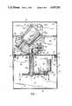
- FIG. 1is a vertical, cross-sectional view taken substantially along the center of a new and improved paint shaker constructed in accordance with the features of the present invention
- FIG. 2is a fragmentary, sectional view looking in the direction of arrows 2--2 of FIG. 1;
- FIG. 3is a fragmentary, vertical, cross-sectional view illustrating adapter means in accordance with the present invention for accommodating containers of different size;
- FIG. 4is a fragmentary, cross-sectional view taken substantially along lines 4--4 of FIG. 1, and illustrating a drive system of the paint shaker in accordance with the features of the present invention
- FIG. 5is a fragmentary, cross-sectional view taken substantially along lines 5--5 of FIG. 1;
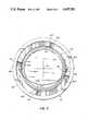
- FIG. 6is a fragmentary, cross-sectional view taken substantially along lines 6--6 of FIG. 1.
- the paint shaker 10includes a cabinet 12 having upstanding side walls 14, a bottom wall 16, and a top 18 hingedly supported from one of the sidewalls 14 by one or more hinges 20 so that the top may pivot upwardly between a closed position as shown and an open position wherein the top of the cabinet is open for loading and unloading.
- the cabinet 12is provided with an intermediate horizontal wall or false bottom 22 which divides the cabinet into an upper working chamber 24 and a lower power chamber 26.
- the upper chamberis provided with inside wall stiffeners 28 of angle iron to minimize noise and vibration.
- the wall 22is supported on a plurality of doughnut-shaped shock mounts 30 which are formed of resilient material to minimize the transmission of noise and vibration to the sidewalls 14 of the cabinet.
- the shock mounts 30are supported on internal horizontal ribs 32 attached on the inside surface of the sidewalls 14. Elongated mounting pins or bolts 34 with nuts 36 at opposite ends are utilized for securing the intermediate wall 22 in place on the shock mounts supported by the wall ribs 32.
- the bottom wall 22 of the upper chamber 24provides support for a downwardly depending, hollow tubular bearing sleeve 38 which is secured at its upper end around the edges of a circular aperture 22a formed in the bottom wall in the central portion thereof.
- the bearing sleeveis formed with a pair of annular shouldered recesses 38a in which are mounted ball bearing rings 40 for supporting a drive shaft 42 driven to rotate about a vertically disposed spin axis 44.
- Motive poweris supplied for rotating the shaft 42 by an electric motor 46 having a downwardly depending, vertical rotor shaft 46a on which is mounted a toothed, drive sprocket 48 for driving a toothed, endless, timing belt 50 entrained around a larger diameter sheave or pulley 52 mounted on the lower end portion of the main drive shaft 42.
- the rotor shaft 46a of the motoris mounted in an annular, bearing sleeve 54 seated in an eccentrically positioned aperture formed ih a circular-shaped, mounting block 56 having an upper flange and seated in an aperture 58a provided in a motor support arm 58.
- one end of the motor support arm 58is attached to the lower end of the shaft sleeve 38 and an opposite, outer end is supported by a rod 60 extending upwardly from the arm and attached to the bottom wall 22 of the upper chamber 24.
- Tensioning of the belt 50is achieved by relative rotation of the eccentric mounting block 56 in the aperture 58a as indicated by an arrow "A" and a radial set screw 62 (FIG. 6) is provided for securing the mounting block in a selected position once the proper belt tension has been attained.
- the shaft 42extends upwardly above the level of the bottom wall 22 of the upper chamber 24 and supports a yoke 64 comprising a pair of opposite, laterally and outwardly extending, upsloping arms 64a and 64b.
- a central portion of the yokeis formed with a recess to accommodate a bushing 66 supported on the upper end portion of the shaft 42 and secured thereto so that the yoke will spin whenever the shaft is rotated.
- a hollow, tubular, bearing sleeve 68is mounted in a cylindrical bore provided in the yoke arms 64a adjacent an outer end portion and the sleeve is formed with internal annular shoulders or recesses at opposite ends to accommodate a pair of ball bearing rings 70 for supporting a bucket spindle 72 mounted for rotation about an inclined spin axis 74.
- the sloping spin axis 74intersects the vertical spin axis 44 of the yoke 64 at an elevated crossover point 76 above the yoke (as shown in FIG. 1) and the respective spin axes 44 and 74 lie on a vertical plane and intersect one another at an acute angle ⁇ .
- the sloped spin axis 74diverges downwardly and outwardly away from the crossover point 76 at the acute angle ⁇ towards the arm segment 64a of the rotating yoke.
- the bucket spindle 72is driven to rotate whenever the yoke 64 is rotated by means of a fixed pulley 78 secured to the bottom wall 22 of the upper mixing chamber 24.
- the fixed pulleyis provided with a central aperture to accommodate the upwardly extending main drive shaft 42 without interference therewith and is drivingly engaged with an endless V-belt 80.
- the runs of the beltpass between a pair of spaced apart, idler pulleys 82 mounted on the underside of the yoke arm 64a outwardly of the spin axis 44.
- the idler pulleysguide, twist and bend the belt runs so that an outer looped end will drivingly engage and track around a spindle drive pulley 84 mounted on a lower end portion of the bucket spindle 72 which extends downwardly from the underside of the yoke arm 64a.
- the endless V-belt 80 entrained around the fixed pulley 78 and bucket drive pulley 84causes the bucket spindle 72 to rotate about the sloping spin axis 74.
- the motor drive pulley 48is smaller in diameter than the main shaft drive pulley 52 in order to effect a reduction in speed so that the drive shaft 42 rotates in a speed range of 300 to 450 RPM.
- the fixed pulley 78 and bucket drive pulley 84are preferably of the same diameter so that the bucket drive spindle 72 rotates at substantially the same speed as the yoke 64.
- the opposite and somewhat shorter arm 64b of the yokeincludes a vertical outer face 64c in order to accommodate a plurality of vertically movable shim plates 86 having elongated vertical slots in the central portion and adapted to serve as a counterweight for balancing the yoke.
- an outermost and larger counterweight element 88is provided to secure the one or more smaller intermediate counterweights between an inner face and the vertical face 64c of the yoke.
- the outer counterweight 88is also formed with an elongated vertical slot in order to accommodate the shank of a threaded cap screw 90 which is used for securing the counter weight in place on the arm 64b.
- the counterweight 88may also be provided with a handle 92 so that an operator may conveniently grasp the yoke 64 to rotate the yoke into a desired position for loading and unloading from the top of the cabinet 12.
- the counterweights 86 and 88may be mounted at selected levels on the vertical face 64c of the yoke 64 in order to provide the best center of gravity for balancing and minimizing the unbalanced forces and vibrations resulting from rotation of the yoke and components carried thereby.
- a circular base plate 94secured onto a shouldered end portion of the spindle and adapted to support the bottom wall 96 of an open ended bucket 98.
- the bucketis open at the top and is adapted to hold a paint can or other container 100 having material therein that is to be mixed and agitated in the apparatus 10.
- the bucket 98includes an ingegral, upstanding, generally frustoconically-shaped sidewall 102 having a plurality of longitudinally extending drive and spacer ribs 102a integrally formed on the inside surface thereof. As illustrated in FIG.
- the ribs 102aare formed with an inwardly facing cylindrical surface segment 103 that is spaced from the spin axis 74 of the bucket by a radial distance slightly greater than the radius of the paint cans 100 or the like that are to be held in the bucket.
- the bucketis dimensioned so that a container placed in the bucket and seated against the bottom wall 96, provides for a center of gravity 104 of the container and contents that is spaced downwardly from and offset to one side of the crossover point 76 and preferably between the intersecting spin axes 44 and 74, respectively. Because of this arrangement, the paint can 100 or other container does not tend to rise or climb out of the bucket 98 when the drive yoke 64 and bucket are rotated about their respective axes 44 and 74 to mix and agitate the contents in the can.
- the upper ends of the drive ribs 102a of the bucketare sharply pointed as at 106 to facilitate loading of the cans and when a can is lowered into the bucket, the handle supporting ears 100a on opposite sides of the can are guided by the pointed upper edges 106 to one side or the other of the ribs 102a. As illustrated in FIG. 2, when the bucket 98 is rotated, the side edges of the ribs 102a engage the ears 100a on the paint can to drive the can to rotate with the bucket.
- Mixing and agitation of the material in a can placed in the bucketis rapid and efficient because the material is subject to intense shear caused by the whirling action simultaneously about a pair of angularly divergent, intersecting spin axes.
- the amount of mixing time requiredis substantially reduced below that required by other types of paint shaker/agitators and no clamps or lids are required to hold the cans in place in the bucekt.
- the bucket 98is dimensioned to accommodate a can 100 of standard size such as a gallon can.
- the apparatus 10may also be provided with a cylindrically-shaped can adapter 108 adapted to accommodate smaller cans such as a quart size can.
- the adapterincludes a pair of separate, interfitting halves 110 preferably formed of light weight urethane foam or similar material and each half is formed with an ear 112 on the outer surface adapted for driving engagement with one of the ribs 102a on the bucket sidewall.
- the diameter and length of the can containing adapteris substantially the same as the standardized dimensions of a gallon paint can 100.
- each adapter halfis provided with a finger recess 110a to facilitate opening the adapter.
- Arrows 110bare provided on the outer surface adjacent the finger recesses to facilitate opening up the adapter to load or unload a quart can in the cylindrical cavity 118 defined therein.
- the cavityis particularly dimensioned to accommodate standard size quart paint cans or the like.
- a quart canis then placed inside the cavity and the halves are then pivoted back together to close and form a cylindrically shaped insert having outer dimensions similar to that of a standard size gallon paint can 100.
- the adapter and the quart size can contained thereinare then bodily placed in the mixer bucket 98 and the motor is energized to rotate the yoke 64 and drive the bucket about their respective spin axes 44 and 74 until mixing is completed.
- the adapter 108is removed from the bucket and the halves 110 opened up so that the quart size can may be removed.
- the center of gravity of the adapter 108 and a quart can and contents placed thereinis maintained in a position identical or closely adjacent to the center of gravity 104 of a gallon can 100 and its contents placed in the bucket 98.
- the center of gravity 104 of the adapter and/or container and its contentsis maintained continuously at a level spaced below the crossover point 76 between the two spin axes 74 and 44.
- the center of gravity 104is maintained in close spaced relation to the vertical spin axis 44 and this minimizes unbalanced forces on the mechanism when the yoke 64 and elements supported thereby are rotated.
- the small size can adapter 108may also be utilized to hold an even smaller sized pint can 120 which may be placed in position in the cavity 118 with the longitudinal axis of the can extending transversely to the longitudinal axis of the adapter.
- the generally lower weight and mass of a pint size can and contents,is readily supported in the cavity 118 without a close fit and usually the smaller pint size can 120 is maintained against the outer surface of the cavity 118 in the adapter 108 while the yoke 64 and spindle 72 are rotating.
- the paint shaker/mixer apparatus 10 of the present inventionprovides an extremely fast and efficient way of mixing flowable materials in closed containers and the like without requiring the containers to be clamped or otherwise positively secured in place. Placement and removal of the containers in the bucket is easy and fast and because of the relative positioning of the center of gravity of the can and its contents with respect to the crossover point between the respective intersecting spin axes, no lids or clamps are needed. The liquids and fluids contained in the cans are subjected to intense shearing action as the yoke and the bucket spindle of the apparatus are rotated simultaneously.
Landscapes
- Chemical & Material Sciences (AREA)
- Chemical Kinetics & Catalysis (AREA)
- Mixers Of The Rotary Stirring Type (AREA)
Abstract
Description
Claims (19)
Priority Applications (1)
| Application Number | Priority Date | Filing Date | Title |
|---|---|---|---|
| US06/094,634US4497581A (en) | 1979-11-15 | 1979-11-15 | Paint shaker |
Applications Claiming Priority (1)
| Application Number | Priority Date | Filing Date | Title |
|---|---|---|---|
| US06/094,634US4497581A (en) | 1979-11-15 | 1979-11-15 | Paint shaker |
Publications (1)
| Publication Number | Publication Date |
|---|---|
| US4497581Atrue US4497581A (en) | 1985-02-05 |
Family
ID=22246279
Family Applications (1)
| Application Number | Title | Priority Date | Filing Date |
|---|---|---|---|
| US06/094,634Expired - LifetimeUS4497581A (en) | 1979-11-15 | 1979-11-15 | Paint shaker |
Country Status (1)
| Country | Link |
|---|---|
| US (1) | US4497581A (en) |
Cited By (66)
| Publication number | Priority date | Publication date | Assignee | Title |
|---|---|---|---|---|
| EP0207335A1 (en)* | 1985-06-20 | 1987-01-07 | Technologie Ag Mikrona | Apparatus for producing impression materials |
| US4834548A (en)* | 1985-02-12 | 1989-05-30 | Skandex Ab | Apparatus for agitating the content of a closed package |
| EP0402668A1 (en)* | 1989-06-15 | 1990-12-19 | THERA Patent GmbH & Co. KG Gesellschaft für industrielle Schutzrechte | Mixing device for pastes |
| US5160198A (en)* | 1989-07-18 | 1992-11-03 | Fillon-Pichon S.A. | Modular structure cabinet for stirrers of paints and similar products |
| US5197802A (en)* | 1991-09-18 | 1993-03-30 | Fluid Management Limited Partnership | Mixing apparatus |
| EP0599783A1 (en)* | 1992-11-23 | 1994-06-01 | HILTI Aktiengesellschaft | Mixing apparatus for flowable material |
| US5443314A (en)* | 1993-07-09 | 1995-08-22 | United Coatings, Inc. | Mixing assembly |
| US5462353A (en)* | 1994-03-10 | 1995-10-31 | United Coatings, Inc. | Shaker with cam operated clamp |
| WO1996017677A1 (en)* | 1994-12-03 | 1996-06-13 | Friedhelm Schneider Kunststof-Verarbeitung | Mixing device |
| US5749652A (en)* | 1994-10-27 | 1998-05-12 | Red Devil Equipment Company | Mixing apparatus and method |
| US5897204A (en)* | 1997-11-25 | 1999-04-27 | Fluid Management | Anti-jamming clutch mechanism for a clamping apparatus |
| US5904421A (en)* | 1994-05-06 | 1999-05-18 | Corob S.R.L. | Device for mixing paints, varnishes and liquid products in general and a method of controlling the device |
| US5906433A (en)* | 1994-10-11 | 1999-05-25 | Corob S.R.L. | Mixer for products generally disposed in containers and a unit particularly adaptable to the mixer, for supporting and clamping at least one of the containers |
| US20020110046A1 (en)* | 2001-01-19 | 2002-08-15 | Robertson James F. | Fluid agitator and conditioner |
| EP1293245A1 (en)* | 2001-09-05 | 2003-03-19 | Hauschild & Co. KG | Mixing device for mixing liquid, flowable or powdery materials |
| WO2003031041A1 (en)* | 2001-10-09 | 2003-04-17 | The Sherwin-Williams Company | Apparatus and method for mixing a fluid dispersion disposed in a container having either a cylindrical or a square shape |
| US20030142583A1 (en)* | 2002-07-23 | 2003-07-31 | Ultrablend Color, Llc | Fluid mixing apparatus adapter bucket |
| US20030179646A1 (en)* | 2002-03-19 | 2003-09-25 | Miller William A. | Fluid mixer for accommodating containers of varying sizes |
| WO2003089124A1 (en)* | 2002-04-17 | 2003-10-30 | Flacktek, Inc. | Centrifugal mixing system |
| US20030214878A1 (en)* | 2002-05-13 | 2003-11-20 | Huckby Dwight R. | Apparatus and method for mixing a fluid dispersion disposed in a container having either a cylindrical or a square shape |
| US20040008573A1 (en)* | 2002-05-10 | 2004-01-15 | Macdonald James E. | Apparatus and method for mixing fluid dispersions disposed in containers of different sizes and construction |
| US20040085855A1 (en)* | 2003-01-21 | 2004-05-06 | Midas Thomas J. | Keyed paint container holder for a paint mixer |
| US20040141412A1 (en)* | 2003-01-21 | 2004-07-22 | Midas Thomas J. | Paint mixer with damping frame |
| US20040149154A1 (en)* | 2000-10-31 | 2004-08-05 | Geddes Pamela A. | Ceramic decal assembly |
| US6796733B2 (en) | 2000-10-31 | 2004-09-28 | International Imaging Materials Inc. | Thermal transfer ribbon with frosting ink layer |
| US20040208083A1 (en)* | 2003-04-18 | 2004-10-21 | Masterchem Industries, Inc. | System for holding paint container |
| US20040240314A1 (en)* | 2003-05-29 | 2004-12-02 | Masterchem Industries, Inc. | System for holding paint container |
| US20050112984A1 (en)* | 2003-11-25 | 2005-05-26 | Grant Hawthorne | Bobble head shaker |
| US20050169102A1 (en)* | 2004-01-30 | 2005-08-04 | Masterchem Industries, Inc. | Container holder platform |
| US20050195685A1 (en)* | 2004-09-27 | 2005-09-08 | Ultrablend Llc | Ergonomic paint mixer |
| US20060002228A1 (en)* | 2004-06-30 | 2006-01-05 | Red Devil Equipment Company | Mixer suspension |
| US20060002229A1 (en)* | 2004-06-30 | 2006-01-05 | Red Devil Equipment Company | Paint mixer |
| US20060021984A1 (en)* | 2001-04-18 | 2006-02-02 | Nottingham John R | Container and lid assembly |
| US7014078B2 (en) | 2001-12-05 | 2006-03-21 | Masterchem Industries Llc | Container |
| WO2006042091A1 (en)* | 2004-10-05 | 2006-04-20 | The Sherwin-Williams Company | Adaptor for holding a container in a bucket of a mixing device, apparatus and method for having paint disposed in a container |
| US20060087914A1 (en)* | 2004-10-25 | 2006-04-27 | Eckart Edmund A Jr | Automated mixing machine for paint bases and colorants |
| US20060109740A1 (en)* | 2004-10-08 | 2006-05-25 | Huckby Dwight R | Apparatus with automatic balancing for mixing paint disposed in containers having different configurations |
| US20060154765A1 (en)* | 2005-01-10 | 2006-07-13 | Wen-Hao Wang | Transmission device for an agitator of impression material |
| US20060258496A1 (en)* | 2005-05-10 | 2006-11-16 | Shu-Lung Wang | Transmission mechanism for dental impression material mixer |
| US20070002682A1 (en)* | 2005-06-29 | 2007-01-04 | Bausch & Lomb Incorporated | Method of producing liquid solutions comprising fusible solid materials |
| US20070002681A1 (en)* | 2005-06-29 | 2007-01-04 | Bausch & Lomb Incorporated | Mixing and deaeration of viscous materials |
| US20070002680A1 (en)* | 2005-06-29 | 2007-01-04 | Bausch & Lomb Incorporated | Method of producing mixtures of thermally labile materials |
| US20070047385A1 (en)* | 2005-08-18 | 2007-03-01 | Hach Ultra Analytics, Inc. | Particulate tester with mixer for analytical application |
| US20070140049A1 (en)* | 2005-12-15 | 2007-06-21 | Red Devil Equipment Company | Adapter for paint mixers |
| US20070247967A1 (en)* | 2006-04-24 | 2007-10-25 | Red Devil Equipment Company | Vortex motion paint mixing machine |
| US20080087352A1 (en)* | 2006-10-16 | 2008-04-17 | Red Lime Products Inc. | System and method for custom formulation, non-adulterating mixing and packaging of personal care products |
| US20080151685A1 (en)* | 2006-12-26 | 2008-06-26 | Shu-Lung Wang | Guarding structure for a mixer of molding material |
| US20080193511A1 (en)* | 2004-12-23 | 2008-08-14 | Ulrich Massing | Manufacture of Lipid-Based Nanoparticles Using a Dual Asymmetric Centrifuge |
| US7438462B1 (en) | 2004-03-18 | 2008-10-21 | Bodie Christine J | System or method for shaking a container |
| CN100437253C (en)* | 2005-09-12 | 2008-11-26 | 长兴开发科技股份有限公司 | Swinging type mixing and homogenizing device |
| US20090040865A1 (en)* | 2007-08-10 | 2009-02-12 | Valspar Sourcing, Inc. | System for securing a container within a mixing machine |
| EP2258467B1 (en)* | 2009-06-04 | 2014-03-19 | Collomix Rühr-und Mischgeräte GmbH | Method and device for mixing liquid, flowable or powdery materials, in particular for mixing automobile repair varnishes for use in spray guns |
| US20140092706A1 (en)* | 2011-06-14 | 2014-04-03 | Hiroshige Ishii | Centrifugal processing device |
| US9907319B2 (en)* | 2015-03-13 | 2018-03-06 | Steak 'n Shake Enterprises, Inc. | Dual-axis rotational mixer for food products |
| WO2018064012A1 (en)* | 2016-09-29 | 2018-04-05 | L'oreal | Apparatus mixing blended composition for skin treatment |
| US20180104662A1 (en)* | 2015-04-17 | 2018-04-19 | Alfa S.R.L. | Mixer for fluid products |
| US20180353919A1 (en)* | 2017-06-09 | 2018-12-13 | Flacktek, Inc. | Metered dispenser catch for asymmetric rotation mixer |
| US20190031427A1 (en)* | 2017-07-31 | 2019-01-31 | V1 Enterprises, LLC | Mixing apparatus, method of making and using the same |
| CN109351264A (en)* | 2018-12-21 | 2019-02-19 | 长江师范学院 | A stirring device for preparing sodium-ion battery slurry |
| US10322419B2 (en)* | 2015-01-16 | 2019-06-18 | Andreas Hettich Gmbh & Co. Kg | Dual centrifuge rotor with damping mass |
| USD913067S1 (en) | 2019-07-01 | 2021-03-16 | V1 Enterprises, LLC | Mixing apparatus |
| US20210299621A1 (en)* | 2020-03-31 | 2021-09-30 | Medisca Pharmaceutique Inc. | Adapter and assembly for pharmaceutical compounding |
| IT202100026975A1 (en) | 2021-10-20 | 2022-01-20 | Hero Europe S R L | MIXING DEVICE FOR FLUID PRODUCTS CONTAINED IN CONTAINERS |
| DE102020007240A1 (en) | 2020-11-27 | 2022-06-15 | Maik Ehrig | 1. Color mixer 2. Sound box |
| WO2022221507A1 (en)* | 2021-04-14 | 2022-10-20 | Maldonado Javier | Mixing apparatus |
| US11883359B2 (en) | 2016-11-10 | 2024-01-30 | Medisca Pharmaceutique Inc. | Adapter for use in a planetary mixer |
Citations (7)
| Publication number | Priority date | Publication date | Assignee | Title |
|---|---|---|---|---|
| US1332019A (en)* | 1918-02-09 | 1920-02-24 | Sarah K Allison | Culinary utensil |
| US3503592A (en)* | 1968-09-18 | 1970-03-31 | George R Taylor Sr | Liquid agitator |
| GB1387402A (en)* | 1971-03-02 | 1975-03-19 | Techno Med Ltd | Mixing process and apparatus |
| US3880408A (en)* | 1973-08-09 | 1975-04-29 | Winter Oy | Device for mixing of paints and toners |
| US3885357A (en)* | 1973-11-19 | 1975-05-27 | Harvey C Hoyt | Orbital agitating apparatus |
| US4146335A (en)* | 1978-03-20 | 1979-03-27 | General Signal Corporation | Containerized solids mixing machine |
| US4235553A (en)* | 1978-09-25 | 1980-11-25 | Sears, Roebuck And Co. | Material mixer |
- 1979
- 1979-11-15USUS06/094,634patent/US4497581A/ennot_activeExpired - Lifetime
Patent Citations (8)
| Publication number | Priority date | Publication date | Assignee | Title |
|---|---|---|---|---|
| US1332019A (en)* | 1918-02-09 | 1920-02-24 | Sarah K Allison | Culinary utensil |
| US3503592A (en)* | 1968-09-18 | 1970-03-31 | George R Taylor Sr | Liquid agitator |
| GB1387402A (en)* | 1971-03-02 | 1975-03-19 | Techno Med Ltd | Mixing process and apparatus |
| US3880408A (en)* | 1973-08-09 | 1975-04-29 | Winter Oy | Device for mixing of paints and toners |
| US3885357A (en)* | 1973-11-19 | 1975-05-27 | Harvey C Hoyt | Orbital agitating apparatus |
| US4146335A (en)* | 1978-03-20 | 1979-03-27 | General Signal Corporation | Containerized solids mixing machine |
| US4235553A (en)* | 1978-09-25 | 1980-11-25 | Sears, Roebuck And Co. | Material mixer |
| US4235553B1 (en)* | 1978-09-25 | 1991-04-02 | Material mixer |
Cited By (127)
| Publication number | Priority date | Publication date | Assignee | Title |
|---|---|---|---|---|
| US4834548A (en)* | 1985-02-12 | 1989-05-30 | Skandex Ab | Apparatus for agitating the content of a closed package |
| EP0207335A1 (en)* | 1985-06-20 | 1987-01-07 | Technologie Ag Mikrona | Apparatus for producing impression materials |
| EP0402668A1 (en)* | 1989-06-15 | 1990-12-19 | THERA Patent GmbH & Co. KG Gesellschaft für industrielle Schutzrechte | Mixing device for pastes |
| US5167448A (en)* | 1989-06-15 | 1992-12-01 | Thera Patent Gmbh & Co. | Mixing apparatus for pastes |
| US5160198A (en)* | 1989-07-18 | 1992-11-03 | Fillon-Pichon S.A. | Modular structure cabinet for stirrers of paints and similar products |
| US5197802A (en)* | 1991-09-18 | 1993-03-30 | Fluid Management Limited Partnership | Mixing apparatus |
| US5551779A (en)* | 1992-11-23 | 1996-09-03 | Hilti Aktiengesellschaft | Mixing apparatus for counterbalancing flowable masses |
| EP0599783A1 (en)* | 1992-11-23 | 1994-06-01 | HILTI Aktiengesellschaft | Mixing apparatus for flowable material |
| US5443314A (en)* | 1993-07-09 | 1995-08-22 | United Coatings, Inc. | Mixing assembly |
| US5462353A (en)* | 1994-03-10 | 1995-10-31 | United Coatings, Inc. | Shaker with cam operated clamp |
| US5904421A (en)* | 1994-05-06 | 1999-05-18 | Corob S.R.L. | Device for mixing paints, varnishes and liquid products in general and a method of controlling the device |
| US5906433A (en)* | 1994-10-11 | 1999-05-25 | Corob S.R.L. | Mixer for products generally disposed in containers and a unit particularly adaptable to the mixer, for supporting and clamping at least one of the containers |
| US5749652A (en)* | 1994-10-27 | 1998-05-12 | Red Devil Equipment Company | Mixing apparatus and method |
| WO1996017677A1 (en)* | 1994-12-03 | 1996-06-13 | Friedhelm Schneider Kunststof-Verarbeitung | Mixing device |
| US5746510A (en)* | 1994-12-03 | 1998-05-05 | Friedhelm Schneider | Mixing device including counterweight |
| US5897204A (en)* | 1997-11-25 | 1999-04-27 | Fluid Management | Anti-jamming clutch mechanism for a clamping apparatus |
| US6796733B2 (en) | 2000-10-31 | 2004-09-28 | International Imaging Materials Inc. | Thermal transfer ribbon with frosting ink layer |
| US20040149154A1 (en)* | 2000-10-31 | 2004-08-05 | Geddes Pamela A. | Ceramic decal assembly |
| US6854386B2 (en) | 2000-10-31 | 2005-02-15 | International Imaging Materials Inc. | Ceramic decal assembly |
| US20050056181A1 (en)* | 2000-10-31 | 2005-03-17 | Geddes Pamela A. | Ceramic decal assembly |
| US7121197B2 (en) | 2000-10-31 | 2006-10-17 | International Imaging Materials, Inc. | Ceramic decal assembly |
| US20020110046A1 (en)* | 2001-01-19 | 2002-08-15 | Robertson James F. | Fluid agitator and conditioner |
| US20060021984A1 (en)* | 2001-04-18 | 2006-02-02 | Nottingham John R | Container and lid assembly |
| US6709151B2 (en)* | 2001-09-05 | 2004-03-23 | Hauschild & Co. Kg | Mixing device for mixing liquid, flowable or powdery materials |
| EP1293245A1 (en)* | 2001-09-05 | 2003-03-19 | Hauschild & Co. KG | Mixing device for mixing liquid, flowable or powdery materials |
| US20060256648A1 (en)* | 2001-10-09 | 2006-11-16 | Huckby Dwight R | Apparatus and method for mixing a fluid dispersion disposed in a container having either a cylindrical or a square shape |
| US7325968B2 (en)* | 2001-10-09 | 2008-02-05 | The Sherwin-Williams Company | Structure for holding either a cylindrical or square shaped container during a mixing operation |
| US7445373B2 (en)* | 2001-10-09 | 2008-11-04 | The Sherwin-Williams Company | Method for mixing a fluid dispersion disposed in a container having either a cylindrical or square shape |
| US7077560B2 (en) | 2001-10-09 | 2006-07-18 | The Sherwin-Williams Company | Structure for holding either a cylindrical or square shaped container during a mixing operation |
| US20080049549A1 (en)* | 2001-10-09 | 2008-02-28 | The Sherwin-Williams Company | Method for Mixing A Fluid Dispersion Disposed in a Container Having Either a Cylindrical or Square Shape |
| US20030107949A1 (en)* | 2001-10-09 | 2003-06-12 | Huckby Dwight R. | Apparatus and method for mixing a fluid dispersion disposed in a container having either a cylindrical or a square shape |
| WO2003031041A1 (en)* | 2001-10-09 | 2003-04-17 | The Sherwin-Williams Company | Apparatus and method for mixing a fluid dispersion disposed in a container having either a cylindrical or a square shape |
| US20040233778A1 (en)* | 2001-10-09 | 2004-11-25 | Huckby Dwight R. | Apparatus and method for mixing a fluid dispersion disposed in a container having either a cylindrical or a square shape |
| US20050002273A1 (en)* | 2001-10-09 | 2005-01-06 | Huckby Dwight R. | Apparatus and method for mixing a fluid dispersion disposed in a container having either a cylindrical or a square shape |
| US6817751B2 (en) | 2001-10-09 | 2004-11-16 | The Sherwin-Williams Company | Apparatus and method for mixing a fluid dispersion disposed in a container having either a cylindrical or a square shape |
| US7156265B2 (en) | 2001-12-05 | 2007-01-02 | Masterchem Industries Llc | Container |
| US7014078B2 (en) | 2001-12-05 | 2006-03-21 | Masterchem Industries Llc | Container |
| US6767126B2 (en)* | 2002-03-19 | 2004-07-27 | Fluid Management, Inc. | Fluid mixer for accommodating containers of varying sizes |
| US20030179646A1 (en)* | 2002-03-19 | 2003-09-25 | Miller William A. | Fluid mixer for accommodating containers of varying sizes |
| US6755565B2 (en)* | 2002-04-17 | 2004-06-29 | Flacktek, Inc. | Deep holder for dual asymmetric centrifugal mixing system |
| WO2003089124A1 (en)* | 2002-04-17 | 2003-10-30 | Flacktek, Inc. | Centrifugal mixing system |
| US7399111B2 (en) | 2002-05-10 | 2008-07-15 | The Sherwin-Williams Company | Apparatus and method for mixing fluid dispersions disposed in containers of different sizes and construction |
| US20040008573A1 (en)* | 2002-05-10 | 2004-01-15 | Macdonald James E. | Apparatus and method for mixing fluid dispersions disposed in containers of different sizes and construction |
| US20030214878A1 (en)* | 2002-05-13 | 2003-11-20 | Huckby Dwight R. | Apparatus and method for mixing a fluid dispersion disposed in a container having either a cylindrical or a square shape |
| US7182505B2 (en) | 2002-05-13 | 2007-02-27 | The Sherwin-Williams Company | Apparatus and method for mixing a fluid dispersion disposed in a container having either a cylindrical or a square shape |
| US20030142583A1 (en)* | 2002-07-23 | 2003-07-31 | Ultrablend Color, Llc | Fluid mixing apparatus adapter bucket |
| US6988824B2 (en) | 2002-07-23 | 2006-01-24 | Ultrablend Color, Llc | Fluid mixing apparatus adapter bucket |
| US20050030834A1 (en)* | 2002-07-23 | 2005-02-10 | Ultrablend Color, Llc | Fluid mixing apparatus adapter bucket |
| US20060062077A1 (en)* | 2002-07-23 | 2006-03-23 | Ultrablend Color, Llc | Fluid mixing apparatus adapter bucket |
| US6953279B2 (en)* | 2003-01-21 | 2005-10-11 | Red Devil Equipment Company | Paint mixer with damping frame |
| US6767125B2 (en)* | 2003-01-21 | 2004-07-27 | Red Devil Equipment Company | Keyed paint container holder for a paint mixer |
| US20040141412A1 (en)* | 2003-01-21 | 2004-07-22 | Midas Thomas J. | Paint mixer with damping frame |
| US20040085855A1 (en)* | 2003-01-21 | 2004-05-06 | Midas Thomas J. | Keyed paint container holder for a paint mixer |
| US6945689B2 (en) | 2003-04-18 | 2005-09-20 | Masterchem Industries, Llc | System for holding paint container |
| US20040208083A1 (en)* | 2003-04-18 | 2004-10-21 | Masterchem Industries, Inc. | System for holding paint container |
| US6945690B2 (en)* | 2003-05-29 | 2005-09-20 | Masterchem Industries, Inc. | System for holding paint container |
| US20040240314A1 (en)* | 2003-05-29 | 2004-12-02 | Masterchem Industries, Inc. | System for holding paint container |
| US20050112984A1 (en)* | 2003-11-25 | 2005-05-26 | Grant Hawthorne | Bobble head shaker |
| US7048605B2 (en) | 2003-11-25 | 2006-05-23 | Grant Hawthorne | Bobble head shaker |
| US20050169102A1 (en)* | 2004-01-30 | 2005-08-04 | Masterchem Industries, Inc. | Container holder platform |
| US7306363B2 (en) | 2004-01-30 | 2007-12-11 | Masterchem Industries Llc | Container holder platform |
| US20080089172A1 (en)* | 2004-01-30 | 2008-04-17 | Masterchem Industries Llc | Container holder platform |
| US7438462B1 (en) | 2004-03-18 | 2008-10-21 | Bodie Christine J | System or method for shaking a container |
| US7182506B2 (en) | 2004-06-30 | 2007-02-27 | Red Devil Equipment Company | Paint mixer balancing apparatus and method |
| US20060002229A1 (en)* | 2004-06-30 | 2006-01-05 | Red Devil Equipment Company | Paint mixer |
| US20060002228A1 (en)* | 2004-06-30 | 2006-01-05 | Red Devil Equipment Company | Mixer suspension |
| US7520660B2 (en) | 2004-06-30 | 2009-04-21 | Red Devil Equipment Company | Mixer suspension |
| US20050195685A1 (en)* | 2004-09-27 | 2005-09-08 | Ultrablend Llc | Ergonomic paint mixer |
| US7654730B2 (en) | 2004-09-27 | 2010-02-02 | Ultrablend Llc | Ergonomic paint mixer |
| US9302232B1 (en)* | 2004-10-05 | 2016-04-05 | The Sherwin-Williams Company | Shaking machine adaptor for containers having different shapes |
| US8485379B2 (en) | 2004-10-05 | 2013-07-16 | The Sherwin-Williams Company | Shaking machine adaptor for containers having different shapes |
| US8845179B2 (en) | 2004-10-05 | 2014-09-30 | The Sherwin-Williams Company | Shaking machine adaptor for containers having different shapes |
| WO2006042091A1 (en)* | 2004-10-05 | 2006-04-20 | The Sherwin-Williams Company | Adaptor for holding a container in a bucket of a mixing device, apparatus and method for having paint disposed in a container |
| US20060109739A1 (en)* | 2004-10-05 | 2006-05-25 | Huckby Dwight R | Shaking machine adaptor for containers having different shapes |
| US8845180B2 (en) | 2004-10-05 | 2014-09-30 | The Sherwin-Williams Company | Shaking machine adaptor for containers having different shapes |
| US20060109740A1 (en)* | 2004-10-08 | 2006-05-25 | Huckby Dwight R | Apparatus with automatic balancing for mixing paint disposed in containers having different configurations |
| US7686502B2 (en) | 2004-10-08 | 2010-03-30 | The Sherwin-Williams Company | Apparatus with automatic balancing for mixing paint disposed in containers having different configurations |
| US8147123B2 (en)* | 2004-10-08 | 2012-04-03 | The Sherwin-Williams Company | Apparatus with automatic balancing for mixing paint disposed in containers having different configurations |
| US20100177592A1 (en)* | 2004-10-08 | 2010-07-15 | The Sherwin-Williams Company | Apparatus with automatic balancing for mixing paint disposed in containers having different configurations |
| US20060087914A1 (en)* | 2004-10-25 | 2006-04-27 | Eckart Edmund A Jr | Automated mixing machine for paint bases and colorants |
| US20080193511A1 (en)* | 2004-12-23 | 2008-08-14 | Ulrich Massing | Manufacture of Lipid-Based Nanoparticles Using a Dual Asymmetric Centrifuge |
| US10662060B2 (en)* | 2004-12-23 | 2020-05-26 | Ulrich Massing | Manufacture of lipid-based nanoparticles using a dual asymmetric centrifuge |
| US20060154765A1 (en)* | 2005-01-10 | 2006-07-13 | Wen-Hao Wang | Transmission device for an agitator of impression material |
| US20060258496A1 (en)* | 2005-05-10 | 2006-11-16 | Shu-Lung Wang | Transmission mechanism for dental impression material mixer |
| US20070002682A1 (en)* | 2005-06-29 | 2007-01-04 | Bausch & Lomb Incorporated | Method of producing liquid solutions comprising fusible solid materials |
| US20070002681A1 (en)* | 2005-06-29 | 2007-01-04 | Bausch & Lomb Incorporated | Mixing and deaeration of viscous materials |
| US20070002680A1 (en)* | 2005-06-29 | 2007-01-04 | Bausch & Lomb Incorporated | Method of producing mixtures of thermally labile materials |
| US20070047385A1 (en)* | 2005-08-18 | 2007-03-01 | Hach Ultra Analytics, Inc. | Particulate tester with mixer for analytical application |
| US7789552B2 (en) | 2005-08-18 | 2010-09-07 | Hach Company | Particulate tester with mixer for analytical application |
| CN100437253C (en)* | 2005-09-12 | 2008-11-26 | 长兴开发科技股份有限公司 | Swinging type mixing and homogenizing device |
| US7497348B2 (en) | 2005-12-15 | 2009-03-03 | Red Devil Equipment Company | Adapter for paint mixers |
| US20070140049A1 (en)* | 2005-12-15 | 2007-06-21 | Red Devil Equipment Company | Adapter for paint mixers |
| US20070247967A1 (en)* | 2006-04-24 | 2007-10-25 | Red Devil Equipment Company | Vortex motion paint mixing machine |
| US7780339B2 (en) | 2006-04-24 | 2010-08-24 | Red Devil Equipment Company | Vortex motion paint mixing machine |
| US20080087352A1 (en)* | 2006-10-16 | 2008-04-17 | Red Lime Products Inc. | System and method for custom formulation, non-adulterating mixing and packaging of personal care products |
| US7837380B2 (en)* | 2006-12-26 | 2010-11-23 | Shu-Lung Wang | Guarding structure for a mixer of molding material |
| US20080151685A1 (en)* | 2006-12-26 | 2008-06-26 | Shu-Lung Wang | Guarding structure for a mixer of molding material |
| US7959345B2 (en) | 2007-08-10 | 2011-06-14 | Valspar Sourcing, Inc. | System for securing a container within a mixing machine |
| US20090040865A1 (en)* | 2007-08-10 | 2009-02-12 | Valspar Sourcing, Inc. | System for securing a container within a mixing machine |
| EP2258467B1 (en)* | 2009-06-04 | 2014-03-19 | Collomix Rühr-und Mischgeräte GmbH | Method and device for mixing liquid, flowable or powdery materials, in particular for mixing automobile repair varnishes for use in spray guns |
| US9321020B2 (en)* | 2011-06-14 | 2016-04-26 | Hiroshige Ishii | Centrifugal processing device |
| US20140092706A1 (en)* | 2011-06-14 | 2014-04-03 | Hiroshige Ishii | Centrifugal processing device |
| US10322419B2 (en)* | 2015-01-16 | 2019-06-18 | Andreas Hettich Gmbh & Co. Kg | Dual centrifuge rotor with damping mass |
| US9907319B2 (en)* | 2015-03-13 | 2018-03-06 | Steak 'n Shake Enterprises, Inc. | Dual-axis rotational mixer for food products |
| US20180104662A1 (en)* | 2015-04-17 | 2018-04-19 | Alfa S.R.L. | Mixer for fluid products |
| WO2018064012A1 (en)* | 2016-09-29 | 2018-04-05 | L'oreal | Apparatus mixing blended composition for skin treatment |
| US10328400B2 (en) | 2016-09-29 | 2019-06-25 | L'oreal | Apparatus mixing blended composition for skin treatment |
| JP2019534140A (en)* | 2016-09-29 | 2019-11-28 | ロレアル | Blend composition mixing device for skin treatment |
| US12403069B2 (en) | 2016-11-10 | 2025-09-02 | Medisca Pharmaceutique Inc. | Adapter for use in a planetary mixer |
| US12396924B2 (en) | 2016-11-10 | 2025-08-26 | Medisca Pharmaceutique Inc. | Adapter for use in a planetary mixer |
| US12295909B2 (en) | 2016-11-10 | 2025-05-13 | Medisca Pharmaceutique Inc | Adapter for use in a planetary mixer |
| US12213941B1 (en) | 2016-11-10 | 2025-02-04 | Medisca Pharmaceutique Inc. | Adapter for use in a planetary mixer |
| US11883359B2 (en) | 2016-11-10 | 2024-01-30 | Medisca Pharmaceutique Inc. | Adapter for use in a planetary mixer |
| US11478763B2 (en)* | 2017-06-09 | 2022-10-25 | Flacktek Speedmixer, Inc. | Metered dispenser catch for asymmetric rotation mixer |
| US20180353919A1 (en)* | 2017-06-09 | 2018-12-13 | Flacktek, Inc. | Metered dispenser catch for asymmetric rotation mixer |
| US20210394997A1 (en)* | 2017-07-31 | 2021-12-23 | V1 Enterprises, LLC | Mixing apparatus, method of making the mixing apparatus and using the mixing apparatus |
| US20190031427A1 (en)* | 2017-07-31 | 2019-01-31 | V1 Enterprises, LLC | Mixing apparatus, method of making and using the same |
| US11111071B2 (en)* | 2017-07-31 | 2021-09-07 | V1 Enterprises, LLC | Mixing apparatus, method of making the mixing apparatus and using the mixing apparatus |
| CN109351264A (en)* | 2018-12-21 | 2019-02-19 | 长江师范学院 | A stirring device for preparing sodium-ion battery slurry |
| CN109351264B (en)* | 2018-12-21 | 2021-01-26 | 长江师范学院 | Stirring device for preparing sodium ion battery slurry |
| USD913067S1 (en) | 2019-07-01 | 2021-03-16 | V1 Enterprises, LLC | Mixing apparatus |
| US11612866B2 (en)* | 2020-03-31 | 2023-03-28 | Medisca Pharmaceutique Inc. | Adapter and assembly for pharmaceutical compounding |
| US20210299621A1 (en)* | 2020-03-31 | 2021-09-30 | Medisca Pharmaceutique Inc. | Adapter and assembly for pharmaceutical compounding |
| DE102020007240A1 (en) | 2020-11-27 | 2022-06-15 | Maik Ehrig | 1. Color mixer 2. Sound box |
| WO2022221507A1 (en)* | 2021-04-14 | 2022-10-20 | Maldonado Javier | Mixing apparatus |
| WO2023067632A1 (en) | 2021-10-20 | 2023-04-27 | Hero Europe S.R.L. | Mixing device for fluid products contained in containers |
| IT202100026975A1 (en) | 2021-10-20 | 2022-01-20 | Hero Europe S R L | MIXING DEVICE FOR FLUID PRODUCTS CONTAINED IN CONTAINERS |
Similar Documents
| Publication | Publication Date | Title |
|---|---|---|
| US4497581A (en) | Paint shaker | |
| EP1525914B1 (en) | Gyroscopic mixer for mixing the content of a closed container | |
| US6817751B2 (en) | Apparatus and method for mixing a fluid dispersion disposed in a container having either a cylindrical or a square shape | |
| CA1132534A (en) | Material tumbler with non-perpendicular rotation axes | |
| US4281936A (en) | Paint mixing and conditioning machine | |
| US5399013A (en) | Mixing device | |
| US3706443A (en) | Agitation method and means | |
| US6953279B2 (en) | Paint mixer with damping frame | |
| US7182505B2 (en) | Apparatus and method for mixing a fluid dispersion disposed in a container having either a cylindrical or a square shape | |
| EP0617998A1 (en) | An agitator for mixing or blending various products, in particular paints, varnishes or the like | |
| US8147123B2 (en) | Apparatus with automatic balancing for mixing paint disposed in containers having different configurations | |
| US6431745B1 (en) | Device and method for mixing and washing liquids and/or solids and for washing containers | |
| US20180104662A1 (en) | Mixer for fluid products | |
| US4277185A (en) | Rotary gravity mixer | |
| WO2006082214A1 (en) | Double axis mixer for liquids in a receptacle, particularly for homogenization of paints | |
| JPH0724285A (en) | Mixing device | |
| US20210299622A1 (en) | Solid-Liquid Mixer | |
| GB2096909A (en) | Paint mixing and conditioning machine | |
| US5556202A (en) | Pivotly mounted drum type mixer | |
| US5468067A (en) | Method for mixing liquid media having different specific weights | |
| CN218490854U (en) | Automatic material shaking-up device | |
| SU1002165A1 (en) | Installation for mixing viscous components | |
| US10766012B2 (en) | Paint mixing device and method |
Legal Events
| Date | Code | Title | Description |
|---|---|---|---|
| STCF | Information on status: patent grant | Free format text:PATENTED CASE | |
| AS | Assignment | Owner name:NORTHERN TRUST COMPANY THE, A BANKING CORP OF IL. Free format text:ASSIGNMENT OF ASSIGNORS INTEREST.;ASSIGNOR:MILLER PAINT EQUIPMENT, LTD.;REEL/FRAME:004691/0537 Effective date:19870413 | |
| AS | Assignment | Owner name:MILLER PAINT EQUIPMENT LIMITED PARTNERSHIP Free format text:CHANGE OF NAME;ASSIGNOR:FLUID MANAGEMENT LIMITED PARTNERSHIP (CHANGED TO);REEL/FRAME:005024/0843 Effective date:19890117 | |
| AS | Assignment | Owner name:FIRST NATIONAL BANK OF CHICAGO, THE Free format text:SECURITY INTEREST;ASSIGNOR:FLUID MANAGEMENT LIMITED PARTNERSHIP, D/B/A MILLER PAINT EQUIPMENT LIMITED PARTNERSHIP;REEL/FRAME:005024/0855 Effective date:19881130 Owner name:MILLER PAINT EQUIPMENT, LTD. Free format text:RELEASED BY SECURED PARTY;ASSIGNOR:NORTHERN TRUST COMPANY, THE;REEL/FRAME:005024/0838 Effective date:19870413 Owner name:FLUID MANAGEMENT LIMITED PARTNERSHIP Free format text:CHANGE OF NAME;ASSIGNOR:MILLER PAINT EQUIPMENT, LTD., (CHANGED TO);REEL/FRAME:005073/0817 Effective date:19871002 | |
| AS | Assignment | Owner name:CONTINENTAL BANK N.A., ILLINOIS Free format text:SECURITY INTEREST;ASSIGNOR:FLUID MANAGEMENT LIMITED PARTNERSHIP;REEL/FRAME:006962/0690 Effective date:19940408 | |
| AS | Assignment | Owner name:FLUID MANAGEMENT LIMITED PARTNERSHIP, ILLINOIS Free format text:RELEASE OF SECURITY INTEREST;ASSIGNOR:BANK OF AMERICA ILLINOIS (F/K/A CONTINENTAL BANK N.A.);REEL/FRAME:008178/0248 Effective date:19960726 Owner name:FLUID MANAGEMENT LIMITED PARTNERSHIP, ILLINOIS Free format text:RELEASE BY SECURED PARTY;ASSIGNOR:FIRST NATIONAL BANK OF CHICAGO;REEL/FRAME:008239/0304 Effective date:19960725 | |
| AS | Assignment | Owner name:FM ACQUISITION CORP., ILLINOIS Free format text:ASSIGNMENT OF ASSIGNORS INTEREST;ASSIGNOR:FLUID MANAGEMENT LIMITED PARTNERSHIP;REEL/FRAME:008209/0581 Effective date:19960729 | |
| AS | Assignment | Owner name:FLUID MANAGEMENT, INC., ILLINOIS Free format text:CHANGE OF NAME;ASSIGNOR:FM ACQUISITION CORP.;REEL/FRAME:008209/0831 Effective date:19960807 |