US4496995A - Down converting a high frame rate signal to a standard TV frame rate signal by skipping preselected video information - Google Patents
Down converting a high frame rate signal to a standard TV frame rate signal by skipping preselected video informationDownload PDFInfo
- Publication number
- US4496995A US4496995AUS06/363,319US36331982AUS4496995AUS 4496995 AUS4496995 AUS 4496995AUS 36331982 AUS36331982 AUS 36331982AUS 4496995 AUS4496995 AUS 4496995A
- Authority
- US
- United States
- Prior art keywords
- camera
- frame rate
- signal
- monitor
- frame
- Prior art date
- Legal status (The legal status is an assumption and is not a legal conclusion. Google has not performed a legal analysis and makes no representation as to the accuracy of the status listed.)
- Expired - Fee Related
Links
- 238000006243chemical reactionMethods0.000claimsabstractdescription12
- 238000012545processingMethods0.000claimsdescription6
- 230000000694effectsEffects0.000abstractdescription11
- 230000009467reductionEffects0.000description37
- 238000000034methodMethods0.000description21
- 230000008569processEffects0.000description11
- 238000010586diagramMethods0.000description8
- 239000000872bufferSubstances0.000description6
- 238000005070samplingMethods0.000description5
- 230000004044responseEffects0.000description3
- 239000007787solidSubstances0.000description3
- 230000001427coherent effectEffects0.000description2
- 238000005286illuminationMethods0.000description2
- 239000011159matrix materialSubstances0.000description2
- 230000003245working effectEffects0.000description2
- 108010076504Protein Sorting SignalsProteins0.000description1
- 230000008859changeEffects0.000description1
- 239000000284extractSubstances0.000description1
- 230000006870functionEffects0.000description1
- 238000003780insertionMethods0.000description1
- 230000037431insertionEffects0.000description1
- 238000007689inspectionMethods0.000description1
- 230000015654memoryEffects0.000description1
- 238000012986modificationMethods0.000description1
- 230000004048modificationEffects0.000description1
- 230000005855radiationEffects0.000description1
- 238000011160researchMethods0.000description1
- 238000012552reviewMethods0.000description1
- 230000003068static effectEffects0.000description1
- 230000007704transitionEffects0.000description1
Images


Classifications
- H—ELECTRICITY
- H04—ELECTRIC COMMUNICATION TECHNIQUE
- H04N—PICTORIAL COMMUNICATION, e.g. TELEVISION
- H04N5/00—Details of television systems
- H04N5/76—Television signal recording
- H04N5/765—Interface circuits between an apparatus for recording and another apparatus
- H04N5/77—Interface circuits between an apparatus for recording and another apparatus between a recording apparatus and a television camera
Definitions
- This inventionrelates to fast frame recorder apparatus for providing slow motion replay and, more particularly, to a technique and apparatus for facilitating the set-up of an electronic camera useful with such apparatus.
- Such fast frame recorderis comprised of a number of major components among which are a video camera having a solid state imager, a tape recorder, and a cathode ray tube (CRT) display monitor.
- the camerais capable of producing signals corresponding to selected frame rates of from 60 to about 2,000 per second; the tape recorder, by recording at one tape speed and appropriately slowing down the tape during playback to a certain predetermined speed, down-converts the camera signals, regardless of the camera frame rate, to a nominal frame rate of 60 per second; the CRT display monitor receives the 60 per second frame rate playback signal from the tape recorder and displays the scene is question at an appropriate slow motion depending upon the selected camera frame rate.
- the quality of the image displayed on the CRT monitoris affected by a variety of "interrelated" conditions among which are (1) the illumination of the scene that was recorded by means of the camera, (2) the camera focus an depth of field, and (3) the selected frame rate at which the camera was operated.
- Thismay be appreciated from, among other things, a realization that at 2,000 frames per second, significantly more scene illumination is necessary than at, say, 60 frames per second, if for no other reason than to produce sufficient charges at the pixel sites of the solid state sensor within the video camera. Too few charges will affect the scene recording one way; too many charges will affect the scene recording a different way. Thus, it had been the practice to implement one of two camera set-up procedures to provide for a good playback display on the CRT monitor.
- the cameraIn the first set-up procedure, the camera is run at the selected frame rate, its signal being recorded, down-converted to 60 frames per second, and then played back through the CRT monitor. In the event the display on the monitor is less than satisfactory, the camera is appropriately adjusted, and the whole recording process repeated. This trial and error process is repeated over and over until the resulting monitor display is satisfactory.
- the cameraIn the second camera set-up procedure, the camera is run at a frame rate of 60 per second, its output signals being serially applied directly (i.e. in E-to-E fashion) to the CRT monitor. Such bypassing of the recorder is possible because the camera and monitor, in this second set-up procedure, are both operative at the same 60 per second frame rate, i.e. signal down-conversion is unnecessary.
- the camerais then adjusted to optimize the display at a frame rate of 60 per second.
- camera set-up parametersare then calculated based on the set-up parameters which were set when operating the camera at 60 frames per second.
- a fast frame recorderhaving (1) a video camera adapted to produce signals corresponding to a variety of frame rates, (2) a variable speed tape recorder adapted to down-convert the frame rate of the camera signals to a reference frame rate by appropriately reducing the recoder tape speed to a reference speed, and (3) a display monitor adapted to receive the reference frame rate signals
- the camera thereofmay be adjusted for various scene and frame rate conditions without need to record the camera frame rate signals (for purposes of signal down-conversion). This is, in accordance with the invention, achieved by selecting a certain line (or lines) from each frame of the camera output signal, and applying such selected lines directly to the display monitor. Skipping from line to line in the camera output signal has the effect of down-converting the frame rate of the camera output signal as required.
- tape recording for camera set-up purposesis obviated and, attendantly, the camera may be operated at any selected rate while, at the same time, the camera optics, scene lighting, etc., may be adjusted to optimize the monitor display.
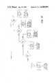
- FIG. 1is a functional block schematic diagram of a fast frame recorder
- FIG. 2is a functional block schematic diagram of a block readable area image sensor
- FIG. 3illustrates, graphically, the concept of video recording using a block readable area image sensor
- FIGS. 4a and 4bdepict the format and content of a video signal produced by block readout of an area image sensor
- FIG. 5shows the format of information as recorded on magnetic tape in the fast frame recorder shown in FIG. 1;
- FIGS. 6a, 6b and 6cshow the relationship between various operational parameters of the fast frame recorder shown in FIG. 1;
- FIG. 7is an electrical schematic diagram of a divide-by-N circuit in the fast frame recorder shown in FIG. 1;
- FIG. 8is a block diagram of a motor drive circuit used in the fast frame recorder shown in FIG. 1;
- FIG. 9is a functional block schematic diagram of a format conversion circuit used in the fast frame recorder shown in FIG. 1;
- FIG. 10is a schematic block diagram illustrating an overview of apparatus according to the invention.
- FIG. 11is a block diagram of the fast frame recorder of FIG. 1 modified to include the camera set-up feature of the invention.
- FIGS. 12-14are diagrammatic showings useful in describing the workings of the apparatus of FIG. 10.
- the fast frame recorderrecords scene information at a fast frame rate and plays back such information at a slower frame rate, thereby allowing slow motion analysis of a moving object.
- the camera frame rate used for recordingis variable between 60 and 2,000 (actually 1,920) frames per second, depending on the desired speed reduction, while the display frame rate is always at 60 frames per second. Accordingly, the apparent speed at which an object moves when viewed upon playback will be reduced by a factor equal to the ratio of the recording frame rate to the playback frame rate.
- the maximum speed reductionis, therefore, about 33 (i.e., 2,000 divided by 60).
- the exposure time for each frameis 1/2000th of a second, which is short enough to provide high resolution images (very little image smear) of even rapidly moving objects.
- variable tape speed magnetic recorderrecords and plays back the camera signal with a recording tape speed to playback tape speed ratio that equals the ratio of the camera frame rate to the display frame rate.
- the magnetic recorderoperates in cooperation with a divide-by-N circuit that selectively alters the frequency content of the signal to be recorded; and, in a manner described in detail below, both the value of "N" and the ratio of the recording to playback tape speed are controlled by the selected speed reduction.
- FIG. 1is a functional block schematic diagram showing the fast frame recorder: Initially, the operator selects the desired speed reduction by means of a speed reduction select circuit 48. Based upon the selected reduction, a camera timing control circuit 54 generates the various clocking signals required to read out a sensor 52 in the camera 50 at a frame rate in accordance with TABLE I:
- the sensor 52is a "block" readable area image sensor.
- the basic concept of block readout of a solid state area image sensoris disclosed in U.S. Pat. No. 4,322,752, filed Jan. 16, 1980 in the name of James A. Bixby, which is hereby incorporated by reference.
- Specific types of block readable sensorsare disclosed in U.S. Pat. No. 4,322,638, filed Jan. 16, 1980 in the names of T. H. Lee and R. P. Khosla, and U.S. Pat. No. 4,330,796, filed Jan. 30, 1980 in the names of C. N. Anagnostopoulos et al, both of which are hereby incorporated by reference.
- FIG. 2shows a block readable sensor 10 that is comprised of an array of photosites (not shown individually) arranged in 192 rows and 240 (plus 16 control pixel positions) columns.
- the sensor 52is formatted into six blocks of 32 photosite rows each. (There need not be any physical demarcation on the sensor itself between such blocks.) Each photosite is readable upon the application thereto of an enablement signal and an address signal.
- a driver 14produces a BLOCK START signal that causes a block select shift register 16 to produce an enablement signal that enables, via block enable line B 1 , all photosite rows within block 1, i.e., rows 1-32.
- column address electronics in the form of a shift register 22sequentially addresses the 240 photosite columns of the entire area image sensor 52. Because the photosite rows within blocks 2-6 (rows 33-192) are not enabled, only photosite rows 1-32 (block 1) are read out at this time. The remaining photosites in the not-enabled blocks continue to integrate charge in response to incident radiation.
- an END OF COLUMN signalsequences the block select shift register 16 to enable, via block enable line B 2 , the block 2 photosite rows, i.e., rows 33-64. Column-wise readout then proceeds as described above for the block 1 photosite rows. This process is repeated until all 6 blocks of photosite rows are read out, at which time an END OF FRAME signal from the block select shift register 16 resets the driver 14 for readout of the next frame.
- Output select gates 18 and an interconnect matrix 20 of conductive bus linesperform the function of a block multiplexer that causes only signals from the 32 photosite rows within the block that is being read out to appear as an output signal.
- FIG. 3illustrates, graphically, how frame information, formatted in blocks as described above, may be recombined to form a video display.
- the camera 50images a scene onto the photosensitive surface of the block readable area image sensor 52. By reading out the sensor in blocks, the scene is “sampled", in effect, by "block sample pulses".
- the frame information(labelled FORMAT) corresponding to each block is shown in "pictorial form" above its respective block sample pulse.
- the block format frame informationis converted to a suitable line sequential signal and applied to a video monitor 40. The scene can then be displayed on the video monitor 40.
- the video signal resulting from block readout of a single frameis comprised of a serial train of block information wherein each block is comprised of 32 lines of video information that correspond to the 32 rows of photosites within each block.
- Each individual line of video information(see FIG. 4b) is an analog signal varying in level proportionate to the level of scene illuminance; and, each line contains 240 picture elements (pixels) that correspond, respectively, to the 240 photosites in each row of photosites.
- each of the 32 line signals that constitutes the analog video signal from the camerais frequency modulated, in an FM modulator circuit 56, on a carrier having a center frequency of 5 MHz. It will be assumed, for purposes of illustration, that the frequency deviation is ⁇ 1.6 MHz.
- a timing track signal containing sync informationis also frequency modulated on a 5 MHz carrier.
- the output of the FM modulator circuit 56is, therefore, comprised of 33 separate, frequency modulated signals, i.e., 32 video signals and a timing track signal.
- the output of the divide-by-N circuit 58is comprised of 33 frequency divided, frequency modulated signals. These signals are applied to a recording head driver circuit 60 that drives a multi-channel longitudinal recorder that includes a 33 channel magnetic recording head 62. The 33 signals are recorded along 33 separate tracks on a magnetic tape 63. Upon recording, the signals retain the block format, as shown in FIG. 5.
- the magnetic tape 63is advanced by a capstan drive that is controlled by a motor drive circuit 65, described in detail with reference to FIG. 8.
- the speed at which the magnetic tape 63 is advanced during recordingis selected to be proportional to the selected speed reduction.
- the recording tape speeds for the selectable speed reductionsis given in TABLE III:
- a slow motion video display of such objectis produced by playing back the recorded information at a constant tape speed of, say, 6 inches per second, irrespective of the originally selected speed reduction.
- the ratio of the recording tape speed to the playback tape speedyields a tape speed reduction ratio that equals the selected speed reduction.
- all reproduced signalshave the same center frequency (f c ) and frequency deviation ( ⁇ f), thereby enabling a fixed frequency demodulator to be used irrespective of the selected speed reduction.
- a speed reduction of 8is selected.
- the FM modulator 56frequency modulates the video signal onto a 5 MHz carrier to produce a frequency modulated video signal having a center frequency equal to 5 MHz and a frequency deviation equal to 1.6 MHz.
- the divide-by-N circuit 58reduces the frequency content of the video signal information by a factor of 4, thereby resulting in a frequency modulated signal having a center frequency equal to 1.25 MHz and a frequency deviation of 0.4 MHz (FIG. 6b).
- This signalis recorded at a tape speed of 50 inches per second. Playing back this signal at a tape speed of 6 inches per second results in a recovered signal that has a center frequency equal to 0.15 MHz, a frequency deviation equal to 0.05 MHz, and a frame rate of 60 frames per second (FIG. 6c).
- the desired speed reduction of 8(more precisely, 8.25) has thus been achieved.
- the signal produced by the playback head 64undergoes signal processing in a preamplifier and equalization circuit 66.
- the processed signalis then demodulated in an FM demodulator circuit 68.
- all reproduced signalshave the same center frequency and frequency deviation.
- the video signalAfter demodulation, the video signal, which is still in the block format shown in FIG. 4a, is converted to a line sequential video signal by a block to serial converter circuit 70 (described in detail in connection with FIG. 9).
- the demodulated timing track signalis diverted to a timing track reader circuit 72 that extracts the sync information.
- the extracted sync informationis used to control a sync generator circuit 74 that produces a standard sync signal at its output.
- a sync insert circuit 76inserts the sync signal into the line sequential video signal from the format converter 70 to produce a video signal for display on the video monitor 78.
- the displayed scene informationwill, as described above, consist of a slow motion replay of the originally recorded scene at the selected speed reduction.
- FIG. 7shows the circuit for only a single video channel since all 33 signals (32 video signals and one timing track signal) are treated identically. Further, while in the above description it has been assumed for purposes of illustration that the speed reduction will be selected from one of five values (33, 17, 8, 3 and 1), the circuit shown in FIG. 7 is designed to handle up to 256 separate speed reductions. The selected speed reduction is applied to a programmable read-only-memory (PROM) 88 which produces on its output lines the 8-bit binary equivalent of 256 minus "N".
- PROMprogrammable read-only-memory
- the four least significant bitsare applied to the load inputs (L 1 , L 2 , L 4 and L 8 ) of a 4-bit binary counter 92.
- the four most significant bitsare applied to the load inputs (L 1 , L 2 , L 4 and L 8 ) of a 4-bit binary counter 94.
- the speed reduction select circuit 48after a time sufficient to allow the data to settle on the load inputs, produces a LOAD signal that causes each of the counters 92 and 94 to be loaded with the count appearing on their respective load inputs. For example, if a speed reduction of 33 was selected ("N" equals 1, see FIG. 6a), the output of the PROM 88 would be the binary equivalent of 256-1, which is 11111111. The binary counter 92 would thus be loaded with 15 (binary 1111), as would the binary counter 94.
- the frequency modulated video signalafter conversion to digital form in a frequency to pulse width modulator 90, clocks the binary counters 92 and 94. Initially, the counter 94 is disabled because of the low state of the carry of counter 92. The digital video signal applied to the clock input of the counter 92, however, causes the counter 92 to start counting from its present value (as preset by the PROM 88) up to 15, at which time the carry goes high thereby enabling the counter 94. On the next positive edge transition of the digital video signal, the counter 94 increments one count from its present count (as presented by the PROM 88), and the carry output of the counter 92 returns to its low state, thereby disabling the counter 94.
- FIG. 8shows the motor drive circuit 65 in detail.
- An 8-bit binary number representing 256 minus "N"(which may be obtained, for example, from the PROM 88 shown in FIG. 7) is applied to a pair of 4-bit counters 100 and 102. Operation of the counters 100 and 102 is identical to that described in connection with the counters 92 and 94 of FIG. 7. The only difference is that each of the counters 100 and 102 is driven by a high frequency clock 104, instead of a digital video signal.
- the output signal appearing at point A 1therefore, consists of a pulse train having a frequency which is less than the clock frequency by a factor of "N".
- This pulse trainis used to control the speed of a capstan motor 110.
- a tachometer 112Connected to the shaft of the capstan motor 110 is a tachometer 112 that produces a signal which varies in amplitude proportionately with motor speed.
- the signal from the tachometer 112passes through a gain control circuit 114 and to an inverting input of a summing circuit 120.
- an incremental encoder 116Also connected to the shaft of the capstan motor 110 is an incremental encoder 116 that produces a pulse train having a repetition rate which varies in proportion to motor speed.
- a phase-frequency detector 124(such as an MC4044) compares the phases of the signals appearing at points A 1 and A 2 and produces an output signal at point B which is applied to the summing circuit 120.
- the output signal from the phase-frequency detector 124is integrated by an integrator 125, the output of which is also applied to the summing circuit 120.
- the output of the summing circuit 120is amplified by an amplifier 126 and is used to control a motor driver 128.
- the signal reproduced upon playbackis formatted, as shown in FIG. 4a, in blocks, wherein each block contains 32 video line signals.
- a block to serial conversion circuit 70(FIG. 1) is used to convert the block format signal to a line sequential signal that is compatible with a standard video monitor.
- the block to serial conversion circuit 70is shown in FIG. 9. (Note: Understanding the operation of the workings of the apparatus of FIG. 9--which also appears as FIG. 12 of U.S. Pat. No. 4,339,775--is important to a good appreciation of the invention.)
- the block format signalis applied to the input data lines D 1 through D 32 of a 1 of 32 data selector 140 that is capable of being randomly addressed.
- Operation of the data selector 140is controlled, in part, by a bit rate clock 142 that increments its count 32 times as fast as the pixel rate. Assume initially, therefore, that the pixel information corresponding to column 1 of lines 1 through 32 appears on the input data lines D 1 through D 32 , respectively.
- the data selector 140sequentially routes the signal appearing on each input data line (D 1 through D 32 ) to the output data line Q at a rate which is 32 times faster than the pixel rate of video information.
- the data selector 140thus samples all 32 input data lines before the pixel information corresponding to column 2 of lines 1 through 32 appears on the input data lines.
- the output signal from the data selector 140is comprised of a series of analog information bits each of which corresponds to a different pixel of video information.
- the order of such information bitsis as follows: column 1 of lines 1 through 32, column 2 of lines 1 through 32, and so on, to column 240 of lines 1 through 32.
- the analog information bitsare converted to their 8-bit binary equivalent by an analog to digital converter 144.
- the resulting stream of binary datais applied to the input data busses of a pair of RAMs (Random Access Memories) 146 and 148, each of which is capable of storing the binary data corresponding to one frame of video signal.
- a write address generator 152generates the address used to write data into the RAMs 146 and 148. Basically, the write address generator 152 is a counter which increments one count for each increment of the bit rate clock 142. The write address generator 152 counts sequentially so that input data is stored in sequential storage locations. A pair of tri-state buffers 156 and 158 determine which of the RAMs 146 and 148 receives the write address.
- a read address generator 154generates a read address used to read data from the RAMs 146 and 148. Again, a pair of tri-state buffers 166 and 168 determine which of the RAMs 146 and 148 receives the read address. There is an important difference between the write address generator 152 and the read address generator 154: While the write address generator 152 counts sequentially, the read address generator 154 counts in such a manner that the signal read from each RAM is in a line-sequential format. This result is accomplished by designing the read address generator 154 so that it repeatedly counts by 32's.
- block one datais read out in the following order: line 1, columns 1 through 240; line 2, columns 1 through 240; and so on, to line 32, columns 1 through 240. This is precisely the order of data that corresponds to a line sequential signal.
- Operation of the tri-state buffers 156, 158, 166 and 168is controlled by a frame clock 150 that causes a frame of information to be written into the RAM 146 while a frame of information is read from the RAM 148. The next frame of information is then written into the RAM 148 while the previously written frame is read from the RAM 146. As information is read from either of the RAMs 146 or 148, it is converted back to analog form by a digital to analog converter 170 to produce an analog line sequential output signal. This signal, after insertion of sync information, is suitable for video display.
- the camera set-up feature of the present inventionis embodied in the prior art apparatus of FIG. 1 by means of particularized switching and programmable logic. In all other respects the apparatus of the invention is exactly the same as has heretofore been disclosed. Before addressing the details of the invention, however, it is considered worthwhile first to provide an overview of the inventive concept. Referring, therefore, to FIG. 10, fast frame recorder apparatus is simplistically shown adaptable to three modes of operation: the record mode R, at variable frame rates; the playback mode P, at a fixed (generally slower) frame rate; and the camera set-up mode S.U. With the FIG. 10 apparatus in the record mode R, signals at the selected frame rate are processed through the record electronics to a record head for recording a magnetic tape run at a suitable speed.
- the camera frame ratecan be many times greater than the frame rate at which the monitor operates, i.e. the monitor receives playback signals and operates at a frame rate of 60 frames per second
- the questionis "How can the monitor perceive an input at 60 frames per second when the camera output, during the set-up operation (S.U.), is at a different (higher) rate?". Since the scene viewed by the camera during set-up is generally a static one, the invention simulates the standard 60 frame per second playback rate by using only some--and discarding other--of the information derived from the variable frame rate camera.
- the monitor line 1 of block 1 . . . line 2 of block 2 . . . line 3 of block 3 and so on down to line 32 of block 32, and then repeating the process over and overthe monitor will see a series of 192 line frames at the rate of 60 per second.
- the display of the monitorwill be a coherent discernible one which will allow the camera focus, exposure, depth of field, scene lighting, etc., to be adjusted while simultaneously viewing the monitor display for purposes of optimizing such display.
- a 60 frame per second monitor inputcan be effected by utilizing, respectively, 2, 4, 8 and 32 lines per block while discarding all other lines. For example, with the camera set to 960 frames per second, lines 1, 2 from block 1 . . . lines 3, 4 from block 2 . . .
- lines 5,6 from block 3 and so on to lines 31, 32 from block 16can be used to compose the first 32 lines of frame 1 of a 60 frame per second input to the monitor. Then the whole process is repeated for lines 33-64 of monitor input frame 1, and so on.
- a camera frame rate of 480 per secondsuch is converted to a 60 per second monitor input frame rate by utilizing, say, lines 1-4 from block 1 . . . lines 5-8 from block 2 . . . and so on to lines 28-32 from block 8. Then, again, the whole process is repeated, and so on.
- the selective orderis for lines 1-8 from block 1 . . . lines 9-17 from block 2, etc.
- no line skippingas would be expected, is practiced.
- FIG. 11has been provided in the same form as that of FIG. 1 . . . modified however to include components for praticing the invention.
- the apparatus of FIG. 11has been "switched" to operate, not in the camera set-up mode, but in the record/playback mode(s). Therefore, when for example the FIG. 11 apparatus is in the throes of slow motion replay, the demodulator 68 applies 32 tracks of video signal information column-by-column to the data selector 140.
- the data selector 140then, in response to addressing by a programmed logic array 500 (e.g. a Signetics 82S100), effects line-by-line scanning of the columns of applied video. Thereafter the columns of video information are buffered (146, 148) in frame-by-frame fashion to convert the video information in parallel to line sequential form as described above.
- a programmed logic array 500e.g. a Signetics 82S100
- the programmed logic array 500effects sampling of the line 1 pixel (B1, C1, L1) . . . the pixels 2 through 32 of column 1 being discarded.
- the programmed logic arrayagain effects sampling of the line 1 pixel (B1, C2, L1) . . . and again pixels 2 through 32 (of column 2) are discarded. This process is repeated for all 240 columns of block 1, with the result being that line 1 of the video information applied via the analog to digital converter 144 to the buffer 146, 148 is exclusively derived from block 1 of the camera output.
- line 2 of the video applied to the bufferis derived exclusively from block 2.
- lines 3 through 192 of the video applied to the bufferare derived line-by-line from the next 190 blocks of video produced by the camera 50 . . . the 192 lines in question constituting the first frame applied to the monitor.
- frame 2 of the video applied to the monitoris derived line-by-line from blocks 193 through 384 . . . frame and line counters 502, 504 keeping track of the line selection effected by means of the programmed logic array.
- Video processing as just describedhas the effect of down-converting the 1,920 per second frame rate of the camera 50 by a factor of 32 to a frame rate of 60 per second.
- the monitorwill provide a coherent display which will allow the camera, scene lighting, etc., to be adjusted while simultaneously viewing the monitor . . . and this despite the fact that the camera and monitor are operating at significantly different frame rates.
Landscapes
- Engineering & Computer Science (AREA)
- Multimedia (AREA)
- Signal Processing (AREA)
- Television Signal Processing For Recording (AREA)
Abstract
Description
TABLE I ______________________________________ FRAME RATE SPEED REDUCTION (frames per second) ______________________________________ 33 2,000 (1,920) 17 1,000 (960) 8 500 (480) 3 200 (192) 1 60 ______________________________________
TABLE II ______________________________________ SPEED REDUCTION N ______________________________________ 33 1 17 2 8 4 3 10 1 33 ______________________________________
TABLE III ______________________________________ RECORDING TAPE SPEED SPEED REDUCTION (inches per second) ______________________________________ 33 200 17 100 8 50 3 20 1 6 ______________________________________
Claims (13)
Priority Applications (1)
| Application Number | Priority Date | Filing Date | Title |
|---|---|---|---|
| US06/363,319US4496995A (en) | 1982-03-29 | 1982-03-29 | Down converting a high frame rate signal to a standard TV frame rate signal by skipping preselected video information |
Applications Claiming Priority (1)
| Application Number | Priority Date | Filing Date | Title |
|---|---|---|---|
| US06/363,319US4496995A (en) | 1982-03-29 | 1982-03-29 | Down converting a high frame rate signal to a standard TV frame rate signal by skipping preselected video information |
Publications (1)
| Publication Number | Publication Date |
|---|---|
| US4496995Atrue US4496995A (en) | 1985-01-29 |
Family
ID=23429734
Family Applications (1)
| Application Number | Title | Priority Date | Filing Date |
|---|---|---|---|
| US06/363,319Expired - Fee RelatedUS4496995A (en) | 1982-03-29 | 1982-03-29 | Down converting a high frame rate signal to a standard TV frame rate signal by skipping preselected video information |
Country Status (1)
| Country | Link |
|---|---|
| US (1) | US4496995A (en) |
Cited By (56)
| Publication number | Priority date | Publication date | Assignee | Title |
|---|---|---|---|---|
| US4680651A (en)* | 1986-08-19 | 1987-07-14 | Eastman Kodak Company | Timing signal dropout compensation circuit |
| US4685002A (en)* | 1985-02-13 | 1987-08-04 | Rca Corporation | Slow motion television system having variable interlace |
| US4789894A (en)* | 1987-03-16 | 1988-12-06 | Eastman Kodak Company | Motion analyzer with interleaved image reproduction |
| US4802024A (en)* | 1986-11-12 | 1989-01-31 | Eastman Kodak Company | Video reproduction apparatus having automatic black and white calibration |
| US4876590A (en)* | 1988-06-17 | 1989-10-24 | Eastman Kodak Company | Low resolution verifier for a still video image |
| WO1991007053A3 (en)* | 1989-11-02 | 1991-06-27 | Eastman Kodak Co | Pre-event/post-event recording in a solid state fast frame recorder |
| US5034811A (en)* | 1990-04-04 | 1991-07-23 | Eastman Kodak Company | Video trigger in a solid state motion analysis system |
| WO1991008644A3 (en)* | 1989-11-20 | 1991-08-08 | Eastman Kodak Co | A solid state fast frame recorder having independently selectable frame rate and exposure |
| EP0441345A1 (en)* | 1990-02-07 | 1991-08-14 | Fuji Photo Film Co., Ltd. | High-definition still picture camera |
| WO1992010064A1 (en)* | 1990-11-26 | 1992-06-11 | Eastman Kodak Company | Video enhancement in a solid state motion analysis system |
| WO1992010908A3 (en)* | 1990-12-14 | 1992-08-06 | Battelle Memorial Institute | High-speed video instrumentation system |
| US5140434A (en)* | 1990-01-29 | 1992-08-18 | Eastman Kodak Company | Record on command recording in a solid state fast frame recorder |
| US5239418A (en)* | 1989-10-17 | 1993-08-24 | Eastman Kodak Company | Single split frame mode for a fast frame recorder |
| US5251036A (en)* | 1990-02-07 | 1993-10-05 | Fuji Photo Film Co., Ltd. | High-definition still picture cameras having a solid-state imaging device with photoelectric conversion elements divided into four fields |
| US5251027A (en)* | 1990-11-26 | 1993-10-05 | Eastman Kodak Company | Telephoto sensor trigger in a solid state motion analysis system |
| US5294978A (en)* | 1991-12-17 | 1994-03-15 | Eastman Kodak Company | Visualization techniques for temporally acquired sequences of images |
| US5452144A (en)* | 1992-09-17 | 1995-09-19 | Sanyo Electric Co., Ltd. | Video tape recorder carrying out field extraction recording and/or reproduction of a video signal |
| US5535064A (en)* | 1985-07-04 | 1996-07-09 | Canon Kabushiki Kaisha | Information signal recording system using different compressing methods to obtain signals for recording along with a corresponding signal indicating the method of compression |
| US5541782A (en)* | 1992-09-28 | 1996-07-30 | Victor Company Of Japan, Ltd. | Magnetic recording and playback apparatus capatible with conventional video signal recording format |
| US5748832A (en)* | 1991-05-28 | 1998-05-05 | Canon Kabushiki Kaisha | Video signal reproducing system |
| US6065072A (en)* | 1997-05-29 | 2000-05-16 | Thermal Wave Imaging, Inc. | Device for selectively passing video frames from a signal series having a first frame rate to obtain a signal series having a second frame rate |
| US6360003B1 (en)* | 1997-08-12 | 2002-03-19 | Kabushiki Kaisha Toshiba | Image processing apparatus |
| US20030011689A1 (en)* | 1999-03-01 | 2003-01-16 | Sanyo Electric Co., Ltd. | Digital camera accommodating recording media from other digital cameras |
| US6510554B1 (en)* | 1998-04-27 | 2003-01-21 | Diva Systems Corporation | Method for generating information sub-streams for FF/REW applications |
| DE10043961C2 (en)* | 2000-09-06 | 2003-03-27 | Fraunhofer Ges Forschung | Combined standard video and high-speed camera |
| WO2007025985A3 (en)* | 2005-08-31 | 2007-05-03 | Quickelberge Luc Van | Method and device for reproducing at a different rate that from the recording |
| US20070219685A1 (en)* | 2006-03-16 | 2007-09-20 | James Plante | Vehicle event recorders with integrated web server |
| US20070257815A1 (en)* | 2006-05-08 | 2007-11-08 | Drivecam, Inc. | System and method for taking risk out of driving |
| US20070260361A1 (en)* | 2006-05-08 | 2007-11-08 | Drivecam, Inc. | System and Method for Selective Review of Event Data |
| US20070260363A1 (en)* | 2006-05-08 | 2007-11-08 | Drivecam, Inc. | System and Method for Wireless Delivery of Event Data |
| US20070257781A1 (en)* | 2006-05-08 | 2007-11-08 | Drivecam, Inc. | System and Method for Identifying Non-Event Profiles |
| US20070257782A1 (en)* | 2006-05-08 | 2007-11-08 | Drivecam, Inc. | System and Method for Multi-Event Capture |
| US20070257804A1 (en)* | 2006-05-08 | 2007-11-08 | Drivecam, Inc. | System and Method for Reducing Driving Risk With Foresight |
| US20070268158A1 (en)* | 2006-05-09 | 2007-11-22 | Drivecam, Inc. | System and Method for Reducing Driving Risk With Insight |
| US20080111666A1 (en)* | 2006-11-09 | 2008-05-15 | Smartdrive Systems Inc. | Vehicle exception event management systems |
| US20090157255A1 (en)* | 2005-12-08 | 2009-06-18 | Smart Drive Systems, Inc. | Vehicle Event Recorder Systems |
| US20100061707A1 (en)* | 2006-10-30 | 2010-03-11 | Ryota Kosakai | Image capturing apparatus and image capturing method |
| US20100092151A1 (en)* | 2007-02-01 | 2010-04-15 | Sony Corporation | Image reproducing apparatus, image reproducing method, image capturing apparatus, and control method therefor |
| US20100226624A1 (en)* | 2009-03-04 | 2010-09-09 | Fujitsu Limited | Information processing apparatus, playback device, recording medium, and information generation method |
| US20110234894A1 (en)* | 2008-09-30 | 2011-09-29 | Trident Microsystems, Inc. | Profile for frame rate conversion |
| US8880279B2 (en) | 2005-12-08 | 2014-11-04 | Smartdrive Systems, Inc. | Memory management in event recording systems |
| US8892310B1 (en) | 2014-02-21 | 2014-11-18 | Smartdrive Systems, Inc. | System and method to detect execution of driving maneuvers |
| US20150062111A1 (en)* | 2013-09-03 | 2015-03-05 | Jong-Ho Roh | Systems, system components and methods for operating the same |
| US8989959B2 (en) | 2006-11-07 | 2015-03-24 | Smartdrive Systems, Inc. | Vehicle operator performance history recording, scoring and reporting systems |
| US9183679B2 (en) | 2007-05-08 | 2015-11-10 | Smartdrive Systems, Inc. | Distributed vehicle event recorder systems having a portable memory data transfer system |
| US9201842B2 (en) | 2006-03-16 | 2015-12-01 | Smartdrive Systems, Inc. | Vehicle event recorder systems and networks having integrated cellular wireless communications systems |
| US20160066000A1 (en)* | 2014-08-27 | 2016-03-03 | ClearOne Inc. | Method for video synchronization in video distribution systems |
| US9501878B2 (en) | 2013-10-16 | 2016-11-22 | Smartdrive Systems, Inc. | Vehicle event playback apparatus and methods |
| US9554080B2 (en) | 2006-11-07 | 2017-01-24 | Smartdrive Systems, Inc. | Power management systems for automotive video event recorders |
| US9610955B2 (en) | 2013-11-11 | 2017-04-04 | Smartdrive Systems, Inc. | Vehicle fuel consumption monitor and feedback systems |
| US9663127B2 (en) | 2014-10-28 | 2017-05-30 | Smartdrive Systems, Inc. | Rail vehicle event detection and recording system |
| US9728228B2 (en) | 2012-08-10 | 2017-08-08 | Smartdrive Systems, Inc. | Vehicle event playback apparatus and methods |
| US9807408B2 (en) | 2014-08-27 | 2017-10-31 | Clearone Communications Hong Kong Ltd. | Control mechanism for video output |
| US9836716B2 (en) | 2006-05-09 | 2017-12-05 | Lytx, Inc. | System and method for reducing driving risk with hindsight |
| US10930093B2 (en) | 2015-04-01 | 2021-02-23 | Smartdrive Systems, Inc. | Vehicle event recording system and method |
| US11069257B2 (en) | 2014-11-13 | 2021-07-20 | Smartdrive Systems, Inc. | System and method for detecting a vehicle event and generating review criteria |
Citations (13)
| Publication number | Priority date | Publication date | Assignee | Title |
|---|---|---|---|---|
| US2940005A (en)* | 1950-07-19 | 1960-06-07 | Moore And Hall | Variable discontinuous interlaced scanning system |
| US3911467A (en)* | 1974-07-25 | 1975-10-07 | Rca Corp | Interlaced readout of charge stored in charge-coupled image sensing array |
| US3958077A (en)* | 1973-10-31 | 1976-05-18 | The University Of Western Australia | Picture transmission systems |
| US4057836A (en)* | 1976-01-22 | 1977-11-08 | Robot Research, Inc. | Slow scan television scan converter |
| US4064540A (en)* | 1975-06-13 | 1977-12-20 | U.S. Philips Corporation | Time registration arrangement provided with a television camera |
| US4125862A (en)* | 1977-03-31 | 1978-11-14 | The United States Of America As Represented By The Secretary Of The Navy | Aspect ratio and scan converter system |
| US4127877A (en)* | 1974-10-02 | 1978-11-28 | Nippon Electric Co., Ltd. | Two-dimensional charge-coupled device for high-resolution image pickup and the like |
| US4133009A (en)* | 1976-01-23 | 1979-01-02 | Basf Aktiengesellschaft | Color video tape recording/playback system |
| DE2751274A1 (en)* | 1977-11-16 | 1979-05-17 | Gao Ges Automation Org | Low frame rate reproduction from video tape - with several camera frames recorded on one track normally assigned to one frame |
| US4204227A (en)* | 1977-03-21 | 1980-05-20 | Rca Corporation | Television picture compressor |
| US4240113A (en)* | 1976-10-14 | 1980-12-16 | Micro Consultants, Limited | Picture manipulation in video systems |
| US4280151A (en)* | 1978-02-24 | 1981-07-21 | Canon Kabushiki Kaisha | High speed image recording system |
| US4395738A (en)* | 1980-11-26 | 1983-07-26 | Rca Corporation | Helical scan tape recording and/or replay apparatus |
- 1982
- 1982-03-29USUS06/363,319patent/US4496995A/ennot_activeExpired - Fee Related
Patent Citations (13)
| Publication number | Priority date | Publication date | Assignee | Title |
|---|---|---|---|---|
| US2940005A (en)* | 1950-07-19 | 1960-06-07 | Moore And Hall | Variable discontinuous interlaced scanning system |
| US3958077A (en)* | 1973-10-31 | 1976-05-18 | The University Of Western Australia | Picture transmission systems |
| US3911467A (en)* | 1974-07-25 | 1975-10-07 | Rca Corp | Interlaced readout of charge stored in charge-coupled image sensing array |
| US4127877A (en)* | 1974-10-02 | 1978-11-28 | Nippon Electric Co., Ltd. | Two-dimensional charge-coupled device for high-resolution image pickup and the like |
| US4064540A (en)* | 1975-06-13 | 1977-12-20 | U.S. Philips Corporation | Time registration arrangement provided with a television camera |
| US4057836A (en)* | 1976-01-22 | 1977-11-08 | Robot Research, Inc. | Slow scan television scan converter |
| US4133009A (en)* | 1976-01-23 | 1979-01-02 | Basf Aktiengesellschaft | Color video tape recording/playback system |
| US4240113A (en)* | 1976-10-14 | 1980-12-16 | Micro Consultants, Limited | Picture manipulation in video systems |
| US4204227A (en)* | 1977-03-21 | 1980-05-20 | Rca Corporation | Television picture compressor |
| US4125862A (en)* | 1977-03-31 | 1978-11-14 | The United States Of America As Represented By The Secretary Of The Navy | Aspect ratio and scan converter system |
| DE2751274A1 (en)* | 1977-11-16 | 1979-05-17 | Gao Ges Automation Org | Low frame rate reproduction from video tape - with several camera frames recorded on one track normally assigned to one frame |
| US4280151A (en)* | 1978-02-24 | 1981-07-21 | Canon Kabushiki Kaisha | High speed image recording system |
| US4395738A (en)* | 1980-11-26 | 1983-07-26 | Rca Corporation | Helical scan tape recording and/or replay apparatus |
Non-Patent Citations (2)
| Title |
|---|
| IBM Technical Disclosure Bulletin, vol. 16, No. 7, Dec. 1973, pp. 2169 2171, (J. E. Mayes and A. L. Snover).* |
| IBM Technical Disclosure Bulletin, vol. 16, No. 7, Dec. 1973, pp. 2169-2171, (J. E. Mayes and A. L. Snover). |
Cited By (121)
| Publication number | Priority date | Publication date | Assignee | Title |
|---|---|---|---|---|
| US4685002A (en)* | 1985-02-13 | 1987-08-04 | Rca Corporation | Slow motion television system having variable interlace |
| US5535064A (en)* | 1985-07-04 | 1996-07-09 | Canon Kabushiki Kaisha | Information signal recording system using different compressing methods to obtain signals for recording along with a corresponding signal indicating the method of compression |
| US4680651A (en)* | 1986-08-19 | 1987-07-14 | Eastman Kodak Company | Timing signal dropout compensation circuit |
| US4802024A (en)* | 1986-11-12 | 1989-01-31 | Eastman Kodak Company | Video reproduction apparatus having automatic black and white calibration |
| US4789894A (en)* | 1987-03-16 | 1988-12-06 | Eastman Kodak Company | Motion analyzer with interleaved image reproduction |
| US4876590A (en)* | 1988-06-17 | 1989-10-24 | Eastman Kodak Company | Low resolution verifier for a still video image |
| US5239418A (en)* | 1989-10-17 | 1993-08-24 | Eastman Kodak Company | Single split frame mode for a fast frame recorder |
| WO1991007053A3 (en)* | 1989-11-02 | 1991-06-27 | Eastman Kodak Co | Pre-event/post-event recording in a solid state fast frame recorder |
| JP3102882B2 (en) | 1989-11-02 | 2000-10-23 | イーストマン・コダック・カンパニー | Pre-event / post-event recording in solid-state high-speed frame recorder |
| US5140436A (en)* | 1989-11-02 | 1992-08-18 | Eastman Kodak Company | Pre-event/post-event recording in a solid state fast frame recorder |
| US5196938A (en)* | 1989-11-20 | 1993-03-23 | Eastman Kodak Company | Solid state fast frame recorder having independently selectable frame rate and exposure |
| WO1991008644A3 (en)* | 1989-11-20 | 1991-08-08 | Eastman Kodak Co | A solid state fast frame recorder having independently selectable frame rate and exposure |
| JP2607856Y2 (en) | 1989-11-20 | 2003-03-31 | イーストマン コダック カンパニー | Solid-state high-speed frame recorder with independently selectable frame rate and exposure |
| US5140434A (en)* | 1990-01-29 | 1992-08-18 | Eastman Kodak Company | Record on command recording in a solid state fast frame recorder |
| US5251036A (en)* | 1990-02-07 | 1993-10-05 | Fuji Photo Film Co., Ltd. | High-definition still picture cameras having a solid-state imaging device with photoelectric conversion elements divided into four fields |
| EP0441345A1 (en)* | 1990-02-07 | 1991-08-14 | Fuji Photo Film Co., Ltd. | High-definition still picture camera |
| US5034811A (en)* | 1990-04-04 | 1991-07-23 | Eastman Kodak Company | Video trigger in a solid state motion analysis system |
| WO1991015917A1 (en)* | 1990-04-04 | 1991-10-17 | Eastman Kodak Company | Video trigger in a solid state motion analysis system |
| WO1992010064A1 (en)* | 1990-11-26 | 1992-06-11 | Eastman Kodak Company | Video enhancement in a solid state motion analysis system |
| US5251027A (en)* | 1990-11-26 | 1993-10-05 | Eastman Kodak Company | Telephoto sensor trigger in a solid state motion analysis system |
| US5301240A (en)* | 1990-12-14 | 1994-04-05 | Battelle Memorial Institute | High-speed video instrumentation system |
| WO1992010908A3 (en)* | 1990-12-14 | 1992-08-06 | Battelle Memorial Institute | High-speed video instrumentation system |
| US5748832A (en)* | 1991-05-28 | 1998-05-05 | Canon Kabushiki Kaisha | Video signal reproducing system |
| US5294978A (en)* | 1991-12-17 | 1994-03-15 | Eastman Kodak Company | Visualization techniques for temporally acquired sequences of images |
| US5619385A (en)* | 1992-09-17 | 1997-04-08 | Sanyo Electric Co., Ltd. | Video tape recorder carrying out field extraction recording and/or reproduction of a video signal |
| US5452144A (en)* | 1992-09-17 | 1995-09-19 | Sanyo Electric Co., Ltd. | Video tape recorder carrying out field extraction recording and/or reproduction of a video signal |
| US5594596A (en)* | 1992-09-17 | 1997-01-14 | Sanyo Electric Co., Ltd. | Video tape recorder carrying out field extraction recording and/or reproduction of a video signal |
| US5541782A (en)* | 1992-09-28 | 1996-07-30 | Victor Company Of Japan, Ltd. | Magnetic recording and playback apparatus capatible with conventional video signal recording format |
| US6065072A (en)* | 1997-05-29 | 2000-05-16 | Thermal Wave Imaging, Inc. | Device for selectively passing video frames from a signal series having a first frame rate to obtain a signal series having a second frame rate |
| US6360003B1 (en)* | 1997-08-12 | 2002-03-19 | Kabushiki Kaisha Toshiba | Image processing apparatus |
| US6510554B1 (en)* | 1998-04-27 | 2003-01-21 | Diva Systems Corporation | Method for generating information sub-streams for FF/REW applications |
| US20030011689A1 (en)* | 1999-03-01 | 2003-01-16 | Sanyo Electric Co., Ltd. | Digital camera accommodating recording media from other digital cameras |
| US7292273B2 (en)* | 1999-03-01 | 2007-11-06 | Sanyo Electric Co., Ltd. | Digital camera accommodating recording media from other digital cameras |
| DE10043961C2 (en)* | 2000-09-06 | 2003-03-27 | Fraunhofer Ges Forschung | Combined standard video and high-speed camera |
| WO2007025985A3 (en)* | 2005-08-31 | 2007-05-03 | Quickelberge Luc Van | Method and device for reproducing at a different rate that from the recording |
| US20080232766A1 (en)* | 2005-08-31 | 2008-09-25 | Luc Van Quickelberge | Method and Device for Reproducing at a Different Rate that From the Recording |
| US8154592B2 (en)* | 2005-08-31 | 2012-04-10 | Tesin Nv | Device and method for inspecting fast repetitive events of defined duration |
| US8880279B2 (en) | 2005-12-08 | 2014-11-04 | Smartdrive Systems, Inc. | Memory management in event recording systems |
| US10878646B2 (en) | 2005-12-08 | 2020-12-29 | Smartdrive Systems, Inc. | Vehicle event recorder systems |
| US9226004B1 (en) | 2005-12-08 | 2015-12-29 | Smartdrive Systems, Inc. | Memory management in event recording systems |
| US9633318B2 (en) | 2005-12-08 | 2017-04-25 | Smartdrive Systems, Inc. | Vehicle event recorder systems |
| US9911253B2 (en) | 2005-12-08 | 2018-03-06 | Smartdrive Systems, Inc. | Memory management in event recording systems |
| US20090157255A1 (en)* | 2005-12-08 | 2009-06-18 | Smart Drive Systems, Inc. | Vehicle Event Recorder Systems |
| US20070219685A1 (en)* | 2006-03-16 | 2007-09-20 | James Plante | Vehicle event recorders with integrated web server |
| US9545881B2 (en) | 2006-03-16 | 2017-01-17 | Smartdrive Systems, Inc. | Vehicle event recorder systems and networks having integrated cellular wireless communications systems |
| US9201842B2 (en) | 2006-03-16 | 2015-12-01 | Smartdrive Systems, Inc. | Vehicle event recorder systems and networks having integrated cellular wireless communications systems |
| US9402060B2 (en) | 2006-03-16 | 2016-07-26 | Smartdrive Systems, Inc. | Vehicle event recorders with integrated web server |
| US8996240B2 (en) | 2006-03-16 | 2015-03-31 | Smartdrive Systems, Inc. | Vehicle event recorders with integrated web server |
| US10404951B2 (en) | 2006-03-16 | 2019-09-03 | Smartdrive Systems, Inc. | Vehicle event recorders with integrated web server |
| US9472029B2 (en) | 2006-03-16 | 2016-10-18 | Smartdrive Systems, Inc. | Vehicle event recorder systems and networks having integrated cellular wireless communications systems |
| US9942526B2 (en) | 2006-03-16 | 2018-04-10 | Smartdrive Systems, Inc. | Vehicle event recorders with integrated web server |
| US9566910B2 (en) | 2006-03-16 | 2017-02-14 | Smartdrive Systems, Inc. | Vehicle event recorder systems and networks having integrated cellular wireless communications systems |
| US9208129B2 (en) | 2006-03-16 | 2015-12-08 | Smartdrive Systems, Inc. | Vehicle event recorder systems and networks having integrated cellular wireless communications systems |
| US9691195B2 (en) | 2006-03-16 | 2017-06-27 | Smartdrive Systems, Inc. | Vehicle event recorder systems and networks having integrated cellular wireless communications systems |
| US20070257781A1 (en)* | 2006-05-08 | 2007-11-08 | Drivecam, Inc. | System and Method for Identifying Non-Event Profiles |
| US20070257804A1 (en)* | 2006-05-08 | 2007-11-08 | Drivecam, Inc. | System and Method for Reducing Driving Risk With Foresight |
| US8373567B2 (en) | 2006-05-08 | 2013-02-12 | Drivecam, Inc. | System and method for identifying non-event profiles |
| US20070257815A1 (en)* | 2006-05-08 | 2007-11-08 | Drivecam, Inc. | System and method for taking risk out of driving |
| US8314708B2 (en) | 2006-05-08 | 2012-11-20 | Drivecam, Inc. | System and method for reducing driving risk with foresight |
| US7804426B2 (en) | 2006-05-08 | 2010-09-28 | Drivecam, Inc. | System and method for selective review of event data |
| US20070257782A1 (en)* | 2006-05-08 | 2007-11-08 | Drivecam, Inc. | System and Method for Multi-Event Capture |
| US20070260363A1 (en)* | 2006-05-08 | 2007-11-08 | Drivecam, Inc. | System and Method for Wireless Delivery of Event Data |
| US20070260361A1 (en)* | 2006-05-08 | 2007-11-08 | Drivecam, Inc. | System and Method for Selective Review of Event Data |
| US7536457B2 (en) | 2006-05-08 | 2009-05-19 | Drivecam, Inc. | System and method for wireless delivery of event data |
| US7659827B2 (en) | 2006-05-08 | 2010-02-09 | Drivecam, Inc. | System and method for taking risk out of driving |
| US9836716B2 (en) | 2006-05-09 | 2017-12-05 | Lytx, Inc. | System and method for reducing driving risk with hindsight |
| US20070268158A1 (en)* | 2006-05-09 | 2007-11-22 | Drivecam, Inc. | System and Method for Reducing Driving Risk With Insight |
| US10235655B2 (en) | 2006-05-09 | 2019-03-19 | Lytx, Inc. | System and method for reducing driving risk with hindsight |
| US9866811B2 (en) | 2006-10-30 | 2018-01-09 | Sony Corporation | Image capturing apparatus and image capturing method |
| US11750937B2 (en) | 2006-10-30 | 2023-09-05 | Sony Group Corporation | Image capturing apparatus and image capturing method |
| US8849090B2 (en) | 2006-10-30 | 2014-09-30 | Sony Corporation | High speed image capturing apparatus and method |
| US11388380B2 (en) | 2006-10-30 | 2022-07-12 | Sony Corporation | Image capturing apparatus and image capturing method |
| US9025929B2 (en) | 2006-10-30 | 2015-05-05 | Sony Corporation | Image capturing apparatus and image capturing method |
| US10986323B2 (en) | 2006-10-30 | 2021-04-20 | Sony Corporation | Image capturing apparatus and image capturing method |
| US20100061707A1 (en)* | 2006-10-30 | 2010-03-11 | Ryota Kosakai | Image capturing apparatus and image capturing method |
| US9538153B1 (en) | 2006-10-30 | 2017-01-03 | Sony Corporation | Image capturing apparatus and image capturing method |
| US9661291B2 (en) | 2006-10-30 | 2017-05-23 | Sony Corporation | Image capturing apparatus and image capturing method |
| US10313648B2 (en) | 2006-10-30 | 2019-06-04 | Sony Corporation | Image capturing apparatus and image capturing method |
| US10708563B2 (en) | 2006-10-30 | 2020-07-07 | Sony Corporation | Image capturing apparatus and image capturing method |
| EP2169947A4 (en)* | 2006-10-30 | 2011-04-06 | Sony Corp | IMAGING DEVICE AND IMAGING METHOD |
| US9554080B2 (en) | 2006-11-07 | 2017-01-24 | Smartdrive Systems, Inc. | Power management systems for automotive video event recorders |
| US10339732B2 (en) | 2006-11-07 | 2019-07-02 | Smartdrive Systems, Inc. | Vehicle operator performance history recording, scoring and reporting systems |
| US10053032B2 (en) | 2006-11-07 | 2018-08-21 | Smartdrive Systems, Inc. | Power management systems for automotive video event recorders |
| US8989959B2 (en) | 2006-11-07 | 2015-03-24 | Smartdrive Systems, Inc. | Vehicle operator performance history recording, scoring and reporting systems |
| US9761067B2 (en) | 2006-11-07 | 2017-09-12 | Smartdrive Systems, Inc. | Vehicle operator performance history recording, scoring and reporting systems |
| US10682969B2 (en) | 2006-11-07 | 2020-06-16 | Smartdrive Systems, Inc. | Power management systems for automotive video event recorders |
| US20080111666A1 (en)* | 2006-11-09 | 2008-05-15 | Smartdrive Systems Inc. | Vehicle exception event management systems |
| US11623517B2 (en) | 2006-11-09 | 2023-04-11 | SmartDriven Systems, Inc. | Vehicle exception event management systems |
| US8868288B2 (en) | 2006-11-09 | 2014-10-21 | Smartdrive Systems, Inc. | Vehicle exception event management systems |
| US9738156B2 (en) | 2006-11-09 | 2017-08-22 | Smartdrive Systems, Inc. | Vehicle exception event management systems |
| US10471828B2 (en) | 2006-11-09 | 2019-11-12 | Smartdrive Systems, Inc. | Vehicle exception event management systems |
| US8903222B2 (en)* | 2007-02-01 | 2014-12-02 | Sony Corporation | Image reproducing apparatus, image reproducing method, image capturing apparatus, and control method therefor |
| US20100092151A1 (en)* | 2007-02-01 | 2010-04-15 | Sony Corporation | Image reproducing apparatus, image reproducing method, image capturing apparatus, and control method therefor |
| US9679424B2 (en) | 2007-05-08 | 2017-06-13 | Smartdrive Systems, Inc. | Distributed vehicle event recorder systems having a portable memory data transfer system |
| US9183679B2 (en) | 2007-05-08 | 2015-11-10 | Smartdrive Systems, Inc. | Distributed vehicle event recorder systems having a portable memory data transfer system |
| US20110234894A1 (en)* | 2008-09-30 | 2011-09-29 | Trident Microsystems, Inc. | Profile for frame rate conversion |
| US10075670B2 (en)* | 2008-09-30 | 2018-09-11 | Entropic Communications, Llc | Profile for frame rate conversion |
| US10362264B2 (en) | 2008-09-30 | 2019-07-23 | Entropic Communications, Llc | Profile for frame rate conversion |
| US20100226624A1 (en)* | 2009-03-04 | 2010-09-09 | Fujitsu Limited | Information processing apparatus, playback device, recording medium, and information generation method |
| US9728228B2 (en) | 2012-08-10 | 2017-08-08 | Smartdrive Systems, Inc. | Vehicle event playback apparatus and methods |
| US20150062111A1 (en)* | 2013-09-03 | 2015-03-05 | Jong-Ho Roh | Systems, system components and methods for operating the same |
| US9355615B2 (en)* | 2013-09-03 | 2016-05-31 | Samsung Electronics Co., Ltd. | Apparatuses, systems, and methods for converting a display driver sync signal into an image sensor sync signal |
| US10019858B2 (en) | 2013-10-16 | 2018-07-10 | Smartdrive Systems, Inc. | Vehicle event playback apparatus and methods |
| US9501878B2 (en) | 2013-10-16 | 2016-11-22 | Smartdrive Systems, Inc. | Vehicle event playback apparatus and methods |
| US10818112B2 (en) | 2013-10-16 | 2020-10-27 | Smartdrive Systems, Inc. | Vehicle event playback apparatus and methods |
| US9610955B2 (en) | 2013-11-11 | 2017-04-04 | Smartdrive Systems, Inc. | Vehicle fuel consumption monitor and feedback systems |
| US11260878B2 (en) | 2013-11-11 | 2022-03-01 | Smartdrive Systems, Inc. | Vehicle fuel consumption monitor and feedback systems |
| US11884255B2 (en) | 2013-11-11 | 2024-01-30 | Smartdrive Systems, Inc. | Vehicle fuel consumption monitor and feedback systems |
| US8892310B1 (en) | 2014-02-21 | 2014-11-18 | Smartdrive Systems, Inc. | System and method to detect execution of driving maneuvers |
| US10497187B2 (en) | 2014-02-21 | 2019-12-03 | Smartdrive Systems, Inc. | System and method to detect execution of driving maneuvers |
| US10249105B2 (en) | 2014-02-21 | 2019-04-02 | Smartdrive Systems, Inc. | System and method to detect execution of driving maneuvers |
| US11250649B2 (en) | 2014-02-21 | 2022-02-15 | Smartdrive Systems, Inc. | System and method to detect execution of driving maneuvers |
| US9953470B1 (en) | 2014-02-21 | 2018-04-24 | Smartdrive Systems, Inc. | System and method to detect execution of driving maneuvers |
| US11734964B2 (en) | 2014-02-21 | 2023-08-22 | Smartdrive Systems, Inc. | System and method to detect execution of driving maneuvers |
| US9594371B1 (en) | 2014-02-21 | 2017-03-14 | Smartdrive Systems, Inc. | System and method to detect execution of driving maneuvers |
| US9973795B2 (en)* | 2014-08-27 | 2018-05-15 | ClearOne Inc. | Method for video synchronization in video distribution systems |
| US9807408B2 (en) | 2014-08-27 | 2017-10-31 | Clearone Communications Hong Kong Ltd. | Control mechanism for video output |
| US20160066000A1 (en)* | 2014-08-27 | 2016-03-03 | ClearOne Inc. | Method for video synchronization in video distribution systems |
| US9663127B2 (en) | 2014-10-28 | 2017-05-30 | Smartdrive Systems, Inc. | Rail vehicle event detection and recording system |
| US11069257B2 (en) | 2014-11-13 | 2021-07-20 | Smartdrive Systems, Inc. | System and method for detecting a vehicle event and generating review criteria |
| US10930093B2 (en) | 2015-04-01 | 2021-02-23 | Smartdrive Systems, Inc. | Vehicle event recording system and method |
Similar Documents
| Publication | Publication Date | Title |
|---|---|---|
| US4496995A (en) | Down converting a high frame rate signal to a standard TV frame rate signal by skipping preselected video information | |
| EP0053184B1 (en) | Fast frame rate augmentation | |
| US4789894A (en) | Motion analyzer with interleaved image reproduction | |
| EP0454842B1 (en) | A solid state fast frame recorder having independently selectable frame rate and exposure | |
| EP0500777B1 (en) | Pre-event/post-event recording in a solid state fast frame recorder | |
| US5140434A (en) | Record on command recording in a solid state fast frame recorder | |
| US4395738A (en) | Helical scan tape recording and/or replay apparatus | |
| US4558376A (en) | Method and system of reproduction of magnetically recorded video signals at speeds differing from recording speed | |
| EP0546688B1 (en) | High speed imaging apparatus | |
| US5239418A (en) | Single split frame mode for a fast frame recorder | |
| US4058835A (en) | Scan conversion apparatus | |
| US4785353A (en) | Block readable video imager having noise compensation | |
| US4796104A (en) | Video signal recording and reproducing apparatus performing time-lapse recordings compatible with standard-type apparatuses | |
| US4775900A (en) | Apparatus for encoding an NRZ digital signal as a BRZ synchronous FM signal | |
| US4745482A (en) | Electronic recorder | |
| US4802024A (en) | Video reproduction apparatus having automatic black and white calibration | |
| US4777541A (en) | FM video demodulator with flutter correction | |
| JP2638799B2 (en) | Video playback device | |
| JP2550567B2 (en) | High-speed imaging device | |
| JPH055745Y2 (en) | ||
| GB1580002A (en) | Processing video signals | |
| CA1102914A (en) | Method and apparatus for recording a single video frame | |
| JPS58107783A (en) | Image recorder/reproducer | |
| DE4127416A1 (en) | SEARCH IMAGE RESISTANCE CIRCUIT FOR USE IN IMAGE SEARCH | |
| JPS5817792A (en) | Image processing method and device for pyroelectric imaging device |
Legal Events
| Date | Code | Title | Description |
|---|---|---|---|
| AS | Assignment | Owner name:EASTMAN TECHNOLOGY, INC., ROCHESTER, NY A NY CORP. Free format text:ASSIGNMENT OF ASSIGNORS INTEREST.;ASSIGNORS:COLLES, JOSEPH H.;BIXBY, JAMES A.;REEL/FRAME:004326/0117 Effective date:19820324 | |
| FEPP | Fee payment procedure | Free format text:PAYOR NUMBER ASSIGNED (ORIGINAL EVENT CODE: ASPN); ENTITY STATUS OF PATENT OWNER: LARGE ENTITY | |
| FPAY | Fee payment | Year of fee payment:4 | |
| FPAY | Fee payment | Year of fee payment:8 | |
| FEPP | Fee payment procedure | Free format text:PAYER NUMBER DE-ASSIGNED (ORIGINAL EVENT CODE: RMPN); ENTITY STATUS OF PATENT OWNER: LARGE ENTITY Free format text:PAYOR NUMBER ASSIGNED (ORIGINAL EVENT CODE: ASPN); ENTITY STATUS OF PATENT OWNER: LARGE ENTITY | |
| AS | Assignment | Owner name:EASTMAN KODAK COMPANY, NEW YORK Free format text:ASSIGNMENT OF ASSIGNORS INTEREST;ASSIGNOR:EASTMAN TECHNOLOGY, INC.;REEL/FRAME:007978/0754 Effective date:19960603 | |
| REMI | Maintenance fee reminder mailed | ||
| LAPS | Lapse for failure to pay maintenance fees | ||
| FP | Lapsed due to failure to pay maintenance fee | Effective date:19970129 | |
| STCH | Information on status: patent discontinuation | Free format text:PATENT EXPIRED DUE TO NONPAYMENT OF MAINTENANCE FEES UNDER 37 CFR 1.362 |