US4496342A - Surge prevention system for an ophthalmic instrument - Google Patents
Surge prevention system for an ophthalmic instrumentDownload PDFInfo
- Publication number
- US4496342A US4496342AUS06/245,664US24566481AUS4496342AUS 4496342 AUS4496342 AUS 4496342AUS 24566481 AUS24566481 AUS 24566481AUS 4496342 AUS4496342 AUS 4496342A
- Authority
- US
- United States
- Prior art keywords
- line
- rate
- evacuation
- flow
- pump
- Prior art date
- Legal status (The legal status is an assumption and is not a legal conclusion. Google has not performed a legal analysis and makes no representation as to the accuracy of the status listed.)
- Expired - Lifetime
Links
- 230000002265preventionEffects0.000titledescription2
- 239000012530fluidSubstances0.000claimsabstractdescription42
- 239000000463materialSubstances0.000claimsabstractdescription20
- 239000007788liquidSubstances0.000claimsabstractdescription11
- 230000008859changeEffects0.000claimsdescription6
- 230000002572peristaltic effectEffects0.000claimsdescription2
- 230000009467reductionEffects0.000claimsdescription2
- 230000000903blocking effectEffects0.000abstractdescription3
- 239000003978infusion fluidSubstances0.000description8
- 230000004410intraocular pressureEffects0.000description8
- 238000001802infusionMethods0.000description7
- 230000007423decreaseEffects0.000description2
- 238000000034methodMethods0.000description2
- 239000000203mixtureSubstances0.000description2
- 230000008569processEffects0.000description2
- 238000001356surgical procedureMethods0.000description2
- 241000124008MammaliaSpecies0.000description1
- FAPWRFPIFSIZLT-UHFFFAOYSA-MSodium chlorideChemical compound[Na+].[Cl-]FAPWRFPIFSIZLT-UHFFFAOYSA-M0.000description1
- 230000009471actionEffects0.000description1
- 230000008878couplingEffects0.000description1
- 238000010168coupling processMethods0.000description1
- 238000005859coupling reactionMethods0.000description1
- 230000003247decreasing effectEffects0.000description1
- 238000010586diagramMethods0.000description1
- 230000000694effectsEffects0.000description1
- 238000004945emulsificationMethods0.000description1
- 239000000839emulsionSubstances0.000description1
- 230000005484gravityEffects0.000description1
- 230000007246mechanismEffects0.000description1
- 238000002406microsurgeryMethods0.000description1
- 239000002245particleSubstances0.000description1
- 230000002441reversible effectEffects0.000description1
- 238000010008shearingMethods0.000description1
- 239000007787solidSubstances0.000description1
- 230000006641stabilisationEffects0.000description1
- 238000011105stabilizationMethods0.000description1
- 239000000725suspensionSubstances0.000description1
- 239000002699waste materialSubstances0.000description1
Images
Classifications
- A—HUMAN NECESSITIES
- A61—MEDICAL OR VETERINARY SCIENCE; HYGIENE
- A61M—DEVICES FOR INTRODUCING MEDIA INTO, OR ONTO, THE BODY; DEVICES FOR TRANSDUCING BODY MEDIA OR FOR TAKING MEDIA FROM THE BODY; DEVICES FOR PRODUCING OR ENDING SLEEP OR STUPOR
- A61M3/00—Medical syringes, e.g. enemata; Irrigators
- A61M3/02—Enemata; Irrigators
- A61M3/0204—Physical characteristics of the irrigation fluid, e.g. conductivity or turbidity
- A61M3/022—Volume; Flow rate
- A—HUMAN NECESSITIES
- A61—MEDICAL OR VETERINARY SCIENCE; HYGIENE
- A61M—DEVICES FOR INTRODUCING MEDIA INTO, OR ONTO, THE BODY; DEVICES FOR TRANSDUCING BODY MEDIA OR FOR TAKING MEDIA FROM THE BODY; DEVICES FOR PRODUCING OR ENDING SLEEP OR STUPOR
- A61M1/00—Suction or pumping devices for medical purposes; Devices for carrying-off, for treatment of, or for carrying-over, body-liquids; Drainage systems
- A61M1/71—Suction drainage systems
- A61M1/74—Suction control
- A—HUMAN NECESSITIES
- A61—MEDICAL OR VETERINARY SCIENCE; HYGIENE
- A61M—DEVICES FOR INTRODUCING MEDIA INTO, OR ONTO, THE BODY; DEVICES FOR TRANSDUCING BODY MEDIA OR FOR TAKING MEDIA FROM THE BODY; DEVICES FOR PRODUCING OR ENDING SLEEP OR STUPOR
- A61M1/00—Suction or pumping devices for medical purposes; Devices for carrying-off, for treatment of, or for carrying-over, body-liquids; Drainage systems
- A61M1/71—Suction drainage systems
- A61M1/77—Suction-irrigation systems
- A—HUMAN NECESSITIES
- A61—MEDICAL OR VETERINARY SCIENCE; HYGIENE
- A61M—DEVICES FOR INTRODUCING MEDIA INTO, OR ONTO, THE BODY; DEVICES FOR TRANSDUCING BODY MEDIA OR FOR TAKING MEDIA FROM THE BODY; DEVICES FOR PRODUCING OR ENDING SLEEP OR STUPOR
- A61M3/00—Medical syringes, e.g. enemata; Irrigators
- A61M3/02—Enemata; Irrigators
- A61M3/0204—Physical characteristics of the irrigation fluid, e.g. conductivity or turbidity
- A61M3/0212—Physical characteristics of the irrigation fluid, e.g. conductivity or turbidity after use
- A—HUMAN NECESSITIES
- A61—MEDICAL OR VETERINARY SCIENCE; HYGIENE
- A61M—DEVICES FOR INTRODUCING MEDIA INTO, OR ONTO, THE BODY; DEVICES FOR TRANSDUCING BODY MEDIA OR FOR TAKING MEDIA FROM THE BODY; DEVICES FOR PRODUCING OR ENDING SLEEP OR STUPOR
- A61M3/00—Medical syringes, e.g. enemata; Irrigators
- A61M3/02—Enemata; Irrigators
- A61M3/0279—Cannula; Nozzles; Tips; their connection means
- A61M3/0287—Cannula; Nozzles; Tips; their connection means with an external liquid collector
- A—HUMAN NECESSITIES
- A61—MEDICAL OR VETERINARY SCIENCE; HYGIENE
- A61M—DEVICES FOR INTRODUCING MEDIA INTO, OR ONTO, THE BODY; DEVICES FOR TRANSDUCING BODY MEDIA OR FOR TAKING MEDIA FROM THE BODY; DEVICES FOR PRODUCING OR ENDING SLEEP OR STUPOR
- A61M1/00—Suction or pumping devices for medical purposes; Devices for carrying-off, for treatment of, or for carrying-over, body-liquids; Drainage systems
- A61M1/71—Suction drainage systems
- A61M1/74—Suction control
- A61M1/75—Intermittent or pulsating suction
- A—HUMAN NECESSITIES
- A61—MEDICAL OR VETERINARY SCIENCE; HYGIENE
- A61M—DEVICES FOR INTRODUCING MEDIA INTO, OR ONTO, THE BODY; DEVICES FOR TRANSDUCING BODY MEDIA OR FOR TAKING MEDIA FROM THE BODY; DEVICES FOR PRODUCING OR ENDING SLEEP OR STUPOR
- A61M3/00—Medical syringes, e.g. enemata; Irrigators
- A61M3/02—Enemata; Irrigators
- A61M3/0233—Enemata; Irrigators characterised by liquid supply means, e.g. from pressurised reservoirs
- A61M3/0241—Enemata; Irrigators characterised by liquid supply means, e.g. from pressurised reservoirs the liquid being supplied by gravity
Definitions
- the materialwhich is generally a mixture of a liquid and solid tissue, the mixture hereafter called a fluid, has either been cut or emulsified or removed by some other process from a portion of the operating site.
- an infusion fluidsuch as a saline solution, is placed into the operating site to replace the removed fluid so that the operating site will stay physically formed or at a given pressure.
- the exchange rate of the fluidhas to be kept at a predetermined level to facilitate removal of the severed tissue to thereby maintain the operating site in a "frozen" condition such that the material to be removed does not move around.
- a small intraocular pressure above atmosphericfor example up to about 40 mmHg is desired during surgery.
- the diameter of the instrument through which the severed tissue is removedis kept small so that the incision into the eye can also be made as small as possible.
- the infusion instrumentwhich can, for example, be a part of the evacuating instrument.
- the small intraocular pressure and the small possible differential pressurelimits the infusion rate.
- the evacuation ratebe kept constant. Arrangements for doing this and for controlling other flow conditions are shown in my U.S. Pat. Nos. 3,812,855 granted May 28, 1974; 3,920,014 granted Nov. 18, 1975; 4,007,742 granted Feb. 15, 1977; 4,019,514 granted Apr. 26, 1977; and 4,117,843 granted Oct. 3, 1978, all of which are assigned to the same assignee.
- the evacuation ratewill stay constant as long as there are no particles which will occlude the evacuation passage of the instrument performing the evacuation.
- the evacuation processcan cause a reduction and fluctuation in intraocular pressure.
- the evacuating flow ratemust not exceed the infusion flow rate to keep the intraocular pressure constant and to prevent eye collapse.
- a constant evacuation ratehas to be maintained where the infusion rate is constant in order to keep a constant intraocular pressure.
- the occlusionis at or near the entrance port of the evacuation instrument and is suddenly removed, there will be a sudden surge of the fluid into the evacuation orifice. This causes a surge of fluid from the eye thereby causing a sudden drop in the intraocular pressure. This results in a turbulence within the eye, the turbulence being particularly noted at the evacuation port of the instrument.
- some sort of a cutting or emulsification mechanismis located at or adjacent to the inlet port of the evacuation instrument. After a period of time, the surge will smooth out and the eye will reach an equilibrium pressure.
- the present inventionis directed to an arrangement for reducing the surge of energy brought about by the sudden removal of a blockage from the evacuation instrument.
- an instrumentis provided having an arrangement wherein a surge prevention fluid flow is provided into the instrument evacuation passage when the instrument senses that the passage was blocked and then suddenly becomes unblocked. This flow acts ge to counteract the sudden surge of fluid into the evacuation line.
- a further objectis to provide a surge protection system for a surgical instrument in which the flow rate, or pressure, in the evacuation line is being sensed and when there is a sudden increase, a line is opened to restore fluid to the evacuation line between the instrument and the evacuation pump.
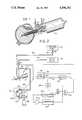
- FIG. 1is an overall plan view, taken partly in cross-section, of a typical instrument for use with a system of the present invention
- FIG. 2is a schematic line diagram showing the various components of the system and their operation with particular emphasis on the fluid flow portions of the system and their various components.
- FIG. 1shows a typical surgical instrument 10 with which the system can be used. It should be understood, however, that the system can be used with any type of instrument or instrument set-up which requires infusion flow of a fluid and/or evacuation of fluid and severed material from an operating site. This includes any of a number of various types of mechanical cutting instruments (e.g. choppers, rotating cutters, guillotine type cutters, etc.) as well as other instruments, for example those of the ultrasonic type, which emulsify material to be removed.
- mechanical cutting instrumentse.g. choppers, rotating cutters, guillotine type cutters, etc.
- other instrumentsfor example those of the ultrasonic type, which emulsify material to be removed.
- the tip of instrument 10is shown as having pierced through a section of the eye, for example after an incision has been made.
- the tip of the instrumentis shown in the vitreous of the eye to remove tissue therefrom or to treat the eye.
- the instrument of FIG. 1also can be used to remove material from other parts of the eye such as the lens or iris. It should be understood that the system can be used with any compatible type of instrument to perform operations or treatment in any portion of the body of a mammal.
- the instrument 10 of FIG. 1includes an electric motor 2, preferably of the reversible type, from which extends a collar 3.
- a fitting 4is fastened onto collar 3 and concentric inner and outer tubular members 12 and 16 extend from fitting 4.
- Inner tube 12defines a central passage 14 through which evacuation takes place over a line 70, to be described below, which communicates with passage 14 through a coupling on fitting 4.
- the space between the inner and the outer tubes 12 and 16defines a passage 17 through which infusion fluid is supplied over a line 66.
- the inner, evacuation flow, member 14 of the instrumenthas an opening 19 at the end thereof through which the evacuation flow communicates with the operation field.
- the infusion flow member 16has an opening 21 in its wall, spaced from opening 19 to avoid interference, through which fluid is injected into the operating field.
- a shaft 6, illustratively shown as having a fluid cutter 7 at the end thereofis located in the inner passage 14.
- the shaftis connected to the motor 2 and rotates in bearings 8 in the fitting 4.
- Shaft 6is preferably biased by a spring 9 so that the cutter 7 will coact with the surface surrounding the evacuation opening 19 to produce a shearing action to cut any tissue therebetween.
- the tip of the instrumentis moved to place the cutter 7 at the site of the material to be severed.
- the evacuation flow from opening 19aids in drawing the material into a relationship so that it can be severed by cutter 7.
- the severed material, in suspension or as part of an emulsionis drawn up passage 14 and is removed via passage 14.
- infusion fluidis supplied over line 66 to the eye through passage 17 and its opening 21. This is to keep the intraocular pressure as constant as possible.
- FIG. 2a portion of the instrument is shown with respect to the outflow line 70 and the infusion line 66.
- the infusion fluidis shown in a bottle 40 and is a control valve 64 of the electromechanical type preferably provided in the line 66. Valve 64 is not critical to the operation of the subject invention so it is not described further.
- a source of surge fluid 55which can be a bottle or a bag which preferably is located at a higher position relative to the source of infusion fluid 40 so that it will have a higher pressure.
- a flow transducer 60is located in the evacuation line 70 which proceeds to a pump 120.
- Pump 120is preferably of the peristaltic type and includes a rotor 126 having three equally spaced rollers 127 mounted thereon which is driven by a motor 125.
- the instrument evacuation line 70is connected to a compressible tubing at the entrance to a housing 122 of generally semi-circular shape.
- the tubing Ahas an outlet 83 to a waste bottle 82.
- the source of surge fluid 55is connected via a line 58 and an electromechanically controlled valve 65 to the output side of the transducer 60 between the evacuation line 70 and the pump 120.
- the transducerproduces an output voltage control signal in proportion to the rate of fluid flow therethrough.
- the pump 120is driven by a pump motor 125, which can be of either the AC or DC type, although a DC motor is illustratively shown, and the output shaft 128 for the pump is shown.
- the pump motor 125has an input voltage control shown by a negative, or common, supply line 135 and a positive supply line 137.
- the positive side 137has a suitable switch 140 therein which can be of the electromechanical (e.g., a relay) or electronic type (e.g., a transistor).
- a mechanically or electromechanically operated switch 144which can be for example, on the operating foot pedal or other similar circuit for the instrument.
- the switch 144would also be connected, for example, to whatever operating portions of the system such as the motor for the handpiece, the ultrasonic generator if an ultrasonic instrument is to be used, etc.
- the output of the transducer 60is applied to an electronic circuit for sensing the various operating conditions of the system and, particularly, conditions in the evacuation line 70.
- the output voltage signal from the transduceris proportional to the flow rate in the evacuation line 70. It is applied to a differentiating amplifier 200 whose output is connected to a comparator circuit 204.
- the output of the comparator 204in turn is applied to one input of an OR circuit 206 and also to an electronic or electromechanically controlled switch 140 in the positive side supply line 135 of the pump 126.
- the differentiator circuit 200is constructed to sense this positively, rapidly increasing voltage. Any suitable conventional circuit can be used, for example, an operational amplifier wired as a differentiator.
- the time constant of the differentiating ampliferis selected so that it will not produce an output signal when the evacuation flow is steady or is decreasing at a gradual rate.
- the output of the differentiating amplifier 200is applied to the comparator 204 which will produce an output signal when the differentiating amplifier 200 produces a signal corresponding to a rate of change of the output signal from the transducer 60 which corresponds to the sudden release of the blocking material. That is, the combination of the differentiating amplifier 200 and the comparator 204 will sense the release of the material blocking the evacuation line.
- the output signal from the comparator 204performs two functions.
- the first functionis controlled through OR circuit 206 to open the valve 65 in the surge fluid line 58.
- valve 65When valve 65 is opened, fluid is immediately dumped into the evacuation line 70 filling up the empty space in the line between the instrument and the pump and, also, in some measure, creating somewhat of a back flow in the line 70 to the instrument evacuation port. This has the effect of equalizing the pressure between the eye and the line so that there is no surge of fluid from the eye into the evacuation line.
- the second functionis for the output signal of the comparator 204 to produce a signal which will open the switch 140 to shut off the motor.
- the surge fluid supplied to the line 70but at the same time the evacuation pump 120 is stopped. This arrangement will equalize the pressure in the eye very rapidly thereby reducing the surge.
- the output signal from the transducer 60is also supplied to a comparator 210 which produces an output signal corresponding to a negative pressure in line 70 above a predetermined value.
- the output of the comparator circuitis applied to an AND gate 212 whose other input is from the positive supply line 137 to the pump motor through an inverter 214.
- the AND gate 212will receive two input signals causing it to produce an output.
- the output from the AND gate 212is applied through the OR circuit 206 to the valve 65 to cause the valve 65 to open. This will apply fluid from the surge fluid supply 55 into the evacuation line 80 thereby effectively placing the evacuation line 70 at a zero, or equilibrium pressure with respect to the operating site.
Landscapes
- Health & Medical Sciences (AREA)
- Heart & Thoracic Surgery (AREA)
- General Health & Medical Sciences (AREA)
- Public Health (AREA)
- Anesthesiology (AREA)
- Hematology (AREA)
- Life Sciences & Earth Sciences (AREA)
- Animal Behavior & Ethology (AREA)
- Engineering & Computer Science (AREA)
- Biomedical Technology (AREA)
- Veterinary Medicine (AREA)
- Vascular Medicine (AREA)
- Pulmonology (AREA)
- Physics & Mathematics (AREA)
- Fluid Mechanics (AREA)
- External Artificial Organs (AREA)
Abstract
Description
During microsurgery in a closed environment, for example intraocular surgery in the eye, a requirement exists for material to be evacuated through an instrument. The material, which is generally a mixture of a liquid and solid tissue, the mixture hereafter called a fluid, has either been cut or emulsified or removed by some other process from a portion of the operating site. At the same time, an infusion fluid such as a saline solution, is placed into the operating site to replace the removed fluid so that the operating site will stay physically formed or at a given pressure. The exchange rate of the fluid has to be kept at a predetermined level to facilitate removal of the severed tissue to thereby maintain the operating site in a "frozen" condition such that the material to be removed does not move around.
In particular, in operating in the eye, a small intraocular pressure above atmospheric, for example up to about 40 mmHg is desired during surgery. The diameter of the instrument through which the severed tissue is removed is kept small so that the incision into the eye can also be made as small as possible. The same holds true with respect to the infusion instrument which can, for example, be a part of the evacuating instrument. The small intraocular pressure and the small possible differential pressure limits the infusion rate.
On the other hand, it is desired that the evacuation rate be kept constant. Arrangements for doing this and for controlling other flow conditions are shown in my U.S. Pat. Nos. 3,812,855 granted May 28, 1974; 3,920,014 granted Nov. 18, 1975; 4,007,742 granted Feb. 15, 1977; 4,019,514 granted Apr. 26, 1977; and 4,117,843 granted Oct. 3, 1978, all of which are assigned to the same assignee. The evacuation rate will stay constant as long as there are no particles which will occlude the evacuation passage of the instrument performing the evacuation. The evacuation process can cause a reduction and fluctuation in intraocular pressure. If the infusion fluid is furnished by gravity feed, for example from an intravenous fluid bottle hung at a predetermined distance above the operating site, the evacuating flow rate must not exceed the infusion flow rate to keep the intraocular pressure constant and to prevent eye collapse. A constant evacuation rate has to be maintained where the infusion rate is constant in order to keep a constant intraocular pressure.
When the evacuation passage of the instrument is occluded, the evacuation flow rate is reduced due to higher resistance to motion in the evacuation line. Blockage of the evacuation line, assuming that the infusion fluid is still being supplied, results in a buildup in the intraocular pressure.
If the occlusion is at or near the entrance port of the evacuation instrument and is suddenly removed, there will be a sudden surge of the fluid into the evacuation orifice. This causes a surge of fluid from the eye thereby causing a sudden drop in the intraocular pressure. This results in a turbulence within the eye, the turbulence being particularly noted at the evacuation port of the instrument. Usually some sort of a cutting or emulsification mechanism is located at or adjacent to the inlet port of the evacuation instrument. After a period of time, the surge will smooth out and the eye will reach an equilibrium pressure.
The present invention is directed to an arrangement for reducing the surge of energy brought about by the sudden removal of a blockage from the evacuation instrument. In accordance with the invention, an instrument is provided having an arrangement wherein a surge prevention fluid flow is provided into the instrument evacuation passage when the instrument senses that the passage was blocked and then suddenly becomes unblocked. This flow acts ge to counteract the sudden surge of fluid into the evacuation line.
It is therefore an object of the present invention to provide a surge protection system for a surgical instrument.
A further object is to provide a surge protection system for a surgical instrument in which the flow rate, or pressure, in the evacuation line is being sensed and when there is a sudden increase, a line is opened to restore fluid to the evacuation line between the instrument and the evacuation pump.
Other objects and advantages of the present invention will become more apparent upon reference to the following specification and annexed drawings in which:
FIG. 1 is an overall plan view, taken partly in cross-section, of a typical instrument for use with a system of the present invention;
FIG. 2 is a schematic line diagram showing the various components of the system and their operation with particular emphasis on the fluid flow portions of the system and their various components.
FIG. 1 shows a typicalsurgical instrument 10 with which the system can be used. It should be understood, however, that the system can be used with any type of instrument or instrument set-up which requires infusion flow of a fluid and/or evacuation of fluid and severed material from an operating site. This includes any of a number of various types of mechanical cutting instruments (e.g. choppers, rotating cutters, guillotine type cutters, etc.) as well as other instruments, for example those of the ultrasonic type, which emulsify material to be removed.
In the embodiment of the invention being described, the tip ofinstrument 10 is shown as having pierced through a section of the eye, for example after an incision has been made. The tip of the instrument is shown in the vitreous of the eye to remove tissue therefrom or to treat the eye. The instrument of FIG. 1 also can be used to remove material from other parts of the eye such as the lens or iris. It should be understood that the system can be used with any compatible type of instrument to perform operations or treatment in any portion of the body of a mammal.
Theinstrument 10 of FIG. 1 includes anelectric motor 2, preferably of the reversible type, from which extends a collar 3. A fitting 4 is fastened onto collar 3 and concentric inner and outertubular members 12 and 16 extend from fitting 4. Inner tube 12 defines acentral passage 14 through which evacuation takes place over a line 70, to be described below, which communicates withpassage 14 through a coupling on fitting 4. The space between the inner and theouter tubes 12 and 16 defines a passage 17 through which infusion fluid is supplied over aline 66.
The inner, evacuation flow,member 14 of the instrument has an opening 19 at the end thereof through which the evacuation flow communicates with the operation field. Theinfusion flow member 16 has an opening 21 in its wall, spaced from opening 19 to avoid interference, through which fluid is injected into the operating field.
Ashaft 6, illustratively shown as having a fluid cutter 7 at the end thereof is located in theinner passage 14. The shaft is connected to themotor 2 and rotates in bearings 8 in the fitting 4.Shaft 6 is preferably biased by a spring 9 so that the cutter 7 will coact with the surface surrounding the evacuation opening 19 to produce a shearing action to cut any tissue therebetween. In operation, the tip of the instrument is moved to place the cutter 7 at the site of the material to be severed. The evacuation flow from opening 19 aids in drawing the material into a relationship so that it can be severed by cutter 7. The severed material, in suspension or as part of an emulsion, is drawn uppassage 14 and is removed viapassage 14.
At the time the evacuation is taking place, infusion fluid is supplied overline 66 to the eye through passage 17 and its opening 21. This is to keep the intraocular pressure as constant as possible.
Referring to FIG. 2, a portion of the instrument is shown with respect to the outflow line 70 and theinfusion line 66. The infusion fluid is shown in abottle 40 and is acontrol valve 64 of the electromechanical type preferably provided in theline 66. Valve 64 is not critical to the operation of the subject invention so it is not described further. There is also shown a source ofsurge fluid 55 which can be a bottle or a bag which preferably is located at a higher position relative to the source ofinfusion fluid 40 so that it will have a higher pressure.
Aflow transducer 60 is located in the evacuation line 70 which proceeds to apump 120.Pump 120 is preferably of the peristaltic type and includes arotor 126 having three equally spaced rollers 127 mounted thereon which is driven by a motor 125. The instrument evacuation line 70 is connected to a compressible tubing at the entrance to ahousing 122 of generally semi-circular shape. The tubing A has an outlet 83 to awaste bottle 82.
As therotor 126 rotates, the fluid ahead of the roller 127 engaging the tubing pushes fluid out of the pump and additional fluid is drawn into the pump. The principles of operation of thepump 120 are well known.
The source ofsurge fluid 55 is connected via aline 58 and an electromechanically controlledvalve 65 to the output side of thetransducer 60 between the evacuation line 70 and thepump 120. The transducer produces an output voltage control signal in proportion to the rate of fluid flow therethrough.
Thepump 120 is driven by a pump motor 125, which can be of either the AC or DC type, although a DC motor is illustratively shown, and theoutput shaft 128 for the pump is shown. The pump motor 125 has an input voltage control shown by a negative, or common,supply line 135 and apositive supply line 137. Thepositive side 137 has asuitable switch 140 therein which can be of the electromechanical (e.g., a relay) or electronic type (e.g., a transistor). Also in series in thepositive line 135 is a mechanically or electromechanically operated switch 144 which can be for example, on the operating foot pedal or other similar circuit for the instrument. The switch 144 would also be connected, for example, to whatever operating portions of the system such as the motor for the handpiece, the ultrasonic generator if an ultrasonic instrument is to be used, etc.
The output of thetransducer 60 is applied to an electronic circuit for sensing the various operating conditions of the system and, particularly, conditions in the evacuation line 70. The output voltage signal from the transducer is proportional to the flow rate in the evacuation line 70. It is applied to a differentiatingamplifier 200 whose output is connected to acomparator circuit 204. The output of thecomparator 204 in turn is applied to one input of an ORcircuit 206 and also to an electronic or electromechanically controlledswitch 140 in the positiveside supply line 135 of thepump 126.
Considering the surge condition which was referred to above, when the evacuation line 70 is blocked, for example by there being occluding material at the evacuation port 19 of the instrument, thepump 120 would normally keep operating. This causes emptying out the evacuation line 70 between the tip of the instrument and the pump. The amount that the line empties depends upon the length of time that the blockage occurs. To understand the operation of the system, consider that switch 144 is closed during normal operation of the instrument and thepump motor 126 is operating. The blockage of the line will cause a decrease in the flow rate measured bytransducer 60. This will cause a changing voltage output of thetransducer 60. This change in the flow rate will generally be gradual since the fluid flow rate decreases gradually as the line 70 empties out. As the fluid empties out of line 70, the negative (suction) pressure builds up since the pump is still running.
When the blockage is removed, the negative pressure built up in the line 70 tends to draw material out from the eye quite rapidly to fill up the empty line 70. When this occurs, thetransducer 60 will produce a rapidly increasing voltage corresponding to the sudden increase in flow rate in line 70.
Thedifferentiator circuit 200 is constructed to sense this positively, rapidly increasing voltage. Any suitable conventional circuit can be used, for example, an operational amplifier wired as a differentiator. The time constant of the differentiating amplifer is selected so that it will not produce an output signal when the evacuation flow is steady or is decreasing at a gradual rate. The output of the differentiatingamplifier 200 is applied to thecomparator 204 which will produce an output signal when the differentiatingamplifier 200 produces a signal corresponding to a rate of change of the output signal from thetransducer 60 which corresponds to the sudden release of the blocking material. That is, the combination of the differentiatingamplifier 200 and thecomparator 204 will sense the release of the material blocking the evacuation line.
To reduce or minimize the inflow surge at the tip of the instrument, the output signal from thecomparator 204 performs two functions. The first function is controlled through ORcircuit 206 to open thevalve 65 in thesurge fluid line 58. Whenvalve 65 is opened, fluid is immediately dumped into the evacuation line 70 filling up the empty space in the line between the instrument and the pump and, also, in some measure, creating somewhat of a back flow in the line 70 to the instrument evacuation port. This has the effect of equalizing the pressure between the eye and the line so that there is no surge of fluid from the eye into the evacuation line.
The second function is for the output signal of thecomparator 204 to produce a signal which will open theswitch 140 to shut off the motor. Thus, not only is the surge fluid supplied to the line 70 but at the same time theevacuation pump 120 is stopped. This arrangement will equalize the pressure in the eye very rapidly thereby reducing the surge.
In the operation of the system, another condition encountered is one wherein the switch 144 is closed, pump 120 is stopped and there is a negative (suction) pressure in the evacuation line 70 but no tissue removal is being accomplished. In this case the negative pressure in theline 80 will tend to gradually remove the fluid and material from the operating site. This condition is not readily discernible, but it is desirable to eliminate it to provide a more optimum stabilization of the field.
To accomplish this, the output signal from thetransducer 60 is also supplied to a comparator 210 which produces an output signal corresponding to a negative pressure in line 70 above a predetermined value. It should be understood that pressure and flow rate in line 70 are related. The output of the comparator circuit is applied to an AND gate 212 whose other input is from thepositive supply line 137 to the pump motor through aninverter 214. Thus, if the switch 144 is open, meaning that no voltage is supplied to the pump motor to cause it to operate, and there is a negative suction on the line 70 above a predetermined level, the AND gate 212 will receive two input signals causing it to produce an output. The output from the AND gate 212 is applied through the ORcircuit 206 to thevalve 65 to cause thevalve 65 to open. This will apply fluid from thesurge fluid supply 55 into theevacuation line 80 thereby effectively placing the evacuation line 70 at a zero, or equilibrium pressure with respect to the operating site.
Claims (8)
1. A material removal system for an opthalmic instrument comprising:
instrument means having an evacuation port for placement into an operating site and a flow line communicating with said evacuation port of said instrument means for evacuating material from said site,
pump means communicating with said flow line for creating a liquid fluid flow through said flow line,
means for sensing the rate of fluid flow in said flow line,
a source of liquid, means for admitting liquid from said source into said flow line at a point between the evacuation port of said instrument and said pump means,
means including comparator means coupled to said sensing means for producing a signal corresponding to a rapid rate change going from a low fluid flow rate condition such that if the flow line were clogged to a high fluid flow rate condition in said flow line above a predetermined level, and
means responsive to said signal for operating said liquid admitting means to supply the liquid from said source into said flow line to aid in filling the empty volume in said line and to tend to equalize the pressure in said line between the operating site and said pump means and for stopping the operation of said pump means.
2. A system as in claim 1 wherein said instrument means includes tubular means defining a passage communicating with said flow line through which the evacuation flow takes place and an opening in the tubular means defining said evacuation port, the blockage of said port or passage causing a reduction in the fluid flow rate in said flow line sensed by said sensing means and the unblocking causing an increase in the fluid flow rate.
3. A system as in claim 2 wherein said means for producing said signal comprises circuit means for sensing the rate of change of flow and for producing said signal when the rate of change exceeds a predetermined level.
4. A system as in claim 3 wherein said circuit means comprises differentiator circuit means coupled to the output of said sensor means, and signal level detecting means coupled to said differentiator circuit means.
5. A system as in claim 1 wherein said pump means comprises a peristaltic pump.
6. A system as in claim 1 further comprising means coupled to said sensing means and said pump means for producing a second signal to operate said admitting means to supply the liquid from said source into said flow line when said pump is inoperative and fluid is flowing in said line at a rate above a predetermined rate.
7. A system as in claim 6 wherein said means for producing said second signal comprises means for detecting a flow rate above a given rate.
8. A material removal system for opthalmic instrument comprising:
said instrument having an evacuation port for placement into an operating site and an evacuation flow line communicating with said port for evacuating material from said site,
pump means communicating with said evacuation flow line for creating an evacuation fluid flow through said flow line and said instrument to said operating site,
means for sensing the rate of fluid flow in said evacuation flow line,
a source of liquid, means for admitting liquid from said source into said evacuation flow line at a point between said instrument and said pump,
means including comparator means coupled to said sensing means for producing a first signal corresponding to a change from a first rate of flow to a second and higher rate of flow at or above a predetermined rate, and
means coupled to said first signal producing means and said pump responsive to said signal to operate said admitting means to supply the liquid from said source to said evacuation flow line when said pump is inoperative and fluid is flowing in said line at a rate above a given predetermined rate.
Priority Applications (1)
| Application Number | Priority Date | Filing Date | Title |
|---|---|---|---|
| US06/245,664US4496342A (en) | 1981-03-20 | 1981-03-20 | Surge prevention system for an ophthalmic instrument |
Applications Claiming Priority (1)
| Application Number | Priority Date | Filing Date | Title |
|---|---|---|---|
| US06/245,664US4496342A (en) | 1981-03-20 | 1981-03-20 | Surge prevention system for an ophthalmic instrument |
Publications (1)
| Publication Number | Publication Date |
|---|---|
| US4496342Atrue US4496342A (en) | 1985-01-29 |
Family
ID=22927587
Family Applications (1)
| Application Number | Title | Priority Date | Filing Date |
|---|---|---|---|
| US06/245,664Expired - LifetimeUS4496342A (en) | 1981-03-20 | 1981-03-20 | Surge prevention system for an ophthalmic instrument |
Country Status (1)
| Country | Link |
|---|---|
| US (1) | US4496342A (en) |
Cited By (89)
| Publication number | Priority date | Publication date | Assignee | Title |
|---|---|---|---|---|
| US4592741A (en)* | 1982-12-29 | 1986-06-03 | Vincent Michel J | Medical apparatus designed for the aspiration of phneumothorax |
| US4622503A (en)* | 1985-09-26 | 1986-11-11 | Medical Instrument Development Laboratories, Inc. | Variable pneumatic output means for use with ophthalmic micro-surgical instruments |
| WO1986007249A1 (en)* | 1985-06-05 | 1986-12-18 | Coopervision, Inc. | Fluid flow control system and connecting fitting |
| WO1987001271A1 (en)* | 1985-09-10 | 1987-03-12 | Thomas Jefferson University | Oxygenated perfluorinated perfusion of the ocular globe |
| US4650461A (en)* | 1985-06-10 | 1987-03-17 | Woods Randall L | Extracapasular cortex irrigation and extraction |
| JPS62500640A (en)* | 1985-06-05 | 1987-03-19 | ザ、クーパー、カンパニーズ、インコ. | Fluid flow control systems and connections therefor |
| US4696667A (en)* | 1986-03-20 | 1987-09-29 | Helmut Masch | Intravascular catheter and method |
| US4705038A (en)* | 1985-01-23 | 1987-11-10 | Dyonics, Inc. | Surgical system for powered instruments |
| US4713052A (en)* | 1984-11-16 | 1987-12-15 | Walter Beck | Apparatus for aspirating secreted fluids from a wound |
| EP0253478A1 (en)* | 1986-07-17 | 1988-01-20 | Mentor O & O Inc. | Ophtalmic aspirator-irrigator |
| US4750902A (en)* | 1985-08-28 | 1988-06-14 | Sonomed Technology, Inc. | Endoscopic ultrasonic aspirators |
| US4755168A (en)* | 1987-01-27 | 1988-07-05 | Pat Romanelli | Medical drainage pump with irrigation |
| US4795423A (en)* | 1980-04-14 | 1989-01-03 | Thomas Jefferson University | Oxygenated perfluorinated perfusion of the ocular globe to treat ischemic retinopathy |
| US4832685A (en)* | 1985-06-05 | 1989-05-23 | Coopervision, Inc. | Fluid flow control system and connecting fitting therefor |
| US4921477A (en)* | 1987-10-14 | 1990-05-01 | The Cooper Companies, Inc. | Surgical irrigation and aspiration system with dampening device |
| US4935005A (en)* | 1985-06-05 | 1990-06-19 | Nestle, S.A. | Opthalmic fluid flow control system |
| US4969870A (en)* | 1989-06-07 | 1990-11-13 | The Regents Of The University Of California | Method and apparatus for intraosseous infusions |
| US5002486A (en)* | 1988-03-30 | 1991-03-26 | Officine Augusto Cattani & C. S.P.A. | Control device for suction systems used in dentistry |
| US5160317A (en)* | 1991-01-03 | 1992-11-03 | Costin John A | Computer controlled smart phacoemulsification method and apparatus |
| US5185002A (en)* | 1991-06-28 | 1993-02-09 | Alcon Surgical, Inc. | Transducer apparatus having water hammer dampening means |
| US5197947A (en)* | 1991-10-24 | 1993-03-30 | University Of New Mexico | Powered clysis and clyser |
| US5279547A (en)* | 1991-01-03 | 1994-01-18 | Alcon Surgical Inc. | Computer controlled smart phacoemulsification method and apparatus |
| USRE34556E (en)* | 1985-01-23 | 1994-03-01 | Smith & Nephew Dyonics Inc. | Surgical system for powered instruments |
| US5312364A (en)* | 1993-08-06 | 1994-05-17 | Pyng | Intraosseous infusion device |
| US5334183A (en)* | 1985-08-28 | 1994-08-02 | Valleylab, Inc. | Endoscopic electrosurgical apparatus |
| WO1996001371A1 (en)* | 1994-07-01 | 1996-01-18 | Baxter International Inc. | Peristaltic pulse pumping systems and methods |
| WO1996032144A1 (en)* | 1995-04-11 | 1996-10-17 | Richard Mackool | Apparatus for controlling fluid flow through a surgical instrument and the temperature of an ultrasonic instrument |
| WO1996038091A1 (en)* | 1995-06-02 | 1996-12-05 | Surgical Design Corporation | Phacoemulsification handpiece, sleeve, and tip |
| US5616120A (en)* | 1995-02-06 | 1997-04-01 | Andrew; Mark S. | Method and apparatus for lenticular liquefaction and aspiration |
| US5630799A (en)* | 1991-08-21 | 1997-05-20 | Smith & Nephew Dyonics Inc. | Fluid management system |
| WO1997037700A1 (en)* | 1996-04-04 | 1997-10-16 | Allergan Sales, Inc. | Method of infusion control during phacoemulsification surgery |
| US5749885A (en)* | 1995-10-02 | 1998-05-12 | Smith & Nephew, Inc. | Surgical instrument with embedded coding element |
| US5817052A (en)* | 1995-12-26 | 1998-10-06 | Pyng Medical Corp. | Apparatus for intraosseous infusion or aspiration |
| US5830176A (en)* | 1995-12-26 | 1998-11-03 | Mackool; Richard J. | Maintenance of pressure within a surgical site during a surgical procedure |
| US5910139A (en)* | 1996-08-29 | 1999-06-08 | Storz Instrument Co. | Numeric keypad simulated on touchscreen |
| US5997528A (en)* | 1996-08-29 | 1999-12-07 | Bausch & Lomb Surgical, Inc. | Surgical system providing automatic reconfiguration |
| US6055458A (en)* | 1997-08-28 | 2000-04-25 | Bausch & Lomb Surgical, Inc. | Modes/surgical functions |
| US6053923A (en)* | 1998-03-17 | 2000-04-25 | Arthrotek, Inc. | Method and apparatus for abrading tissue |
| US6086576A (en)* | 1996-08-29 | 2000-07-11 | Bausch & Lomb Surgical, Inc. | Automatically switching the termination of a communications bus |
| US6117126A (en)* | 1996-08-29 | 2000-09-12 | Bausch & Lomb Surgical, Inc. | Surgical module with independent microprocessor-based communication |
| US6251113B1 (en) | 1996-08-29 | 2001-06-26 | Bausch & Lomb Surgical, Inc. | Ophthalmic microsurgical system employing surgical module employing flash EEPROM and reprogrammable modules |
| US6544211B1 (en) | 1995-02-06 | 2003-04-08 | Mark S. Andrew | Tissue liquefaction and aspiration |
| WO2003047652A1 (en)* | 2001-11-30 | 2003-06-12 | Bausch & Lomb Incorporated | Collection reservoir for use with flow meter control system |
| WO2003047654A1 (en)* | 2001-11-30 | 2003-06-12 | Bausch & Lomb Incorporated | Aspiration tube for use with flow meter control system |
| US20030161858A1 (en)* | 2000-04-11 | 2003-08-28 | Lars Lidgren | Injectable bone mineral substitute material |
| US6676629B2 (en) | 1995-02-06 | 2004-01-13 | Mark S. Andrew | Tissue liquefaction and aspiration for dental treatment |
| US20050119746A1 (en)* | 2001-12-20 | 2005-06-02 | Lars Lidgren | Bone mineral substitute |
| US20050209560A1 (en)* | 2004-03-22 | 2005-09-22 | Alcon, Inc. | Method of controlling a surgical system based on a rate of change of an operating parameter |
| US20050209561A1 (en)* | 2004-03-22 | 2005-09-22 | Raphael Gordon | Method of detecting surgical events |
| US20050228425A1 (en)* | 2004-03-22 | 2005-10-13 | Alcon, Inc. | Method of controlling a surgical system based on a load on the cutting tip of a handpiece |
| US20050267504A1 (en)* | 2004-03-22 | 2005-12-01 | Alcon, Inc. | Method of controlling a surgical system based on irrigation flow |
| US20050277869A1 (en)* | 2004-03-22 | 2005-12-15 | Alcon, Inc. | Method of operating an ultrasound handpiece |
| US20060036180A1 (en)* | 2004-08-12 | 2006-02-16 | Mikhail Boukhny | Ultrasonic handpiece |
| US20060041220A1 (en)* | 2004-08-12 | 2006-02-23 | Alcon, Inc. | Ultrasound handpiece |
| US7011644B1 (en) | 1995-02-06 | 2006-03-14 | Andrew Mark S | Tissue liquefaction and aspiration for dental treatment |
| US20070041906A1 (en)* | 2003-03-05 | 2007-02-22 | Lars Lidgren | Bone substitute composition |
| US20070161943A1 (en)* | 2003-11-11 | 2007-07-12 | Lars Lidgren | Device for providing spongy bone with bone substitute and/or bone reinforcing material, bone substitute and/or bone reinforcing material and method |
| EP1897568A1 (en)* | 2006-09-08 | 2008-03-12 | Carl Zeiss Surgical GmbH | Surgical system |
| US20080172076A1 (en)* | 2006-11-01 | 2008-07-17 | Alcon, Inc. | Ultrasound apparatus and method of use |
| US20080281253A1 (en)* | 2007-05-10 | 2008-11-13 | Injev Valentine P | Method of Operating an Ultrasound Handpiece |
| US20080286331A1 (en)* | 2000-07-17 | 2008-11-20 | Bone Support Ab | Composition for an injectable bone mineral substitute material |
| US20080319451A1 (en)* | 2007-06-21 | 2008-12-25 | Jaime Zacharias | Post-occlusion chamber collapse suppressing system for a surgical apparatus and method of use |
| US20080319374A1 (en)* | 2007-06-19 | 2008-12-25 | Jaime Zacharias | Post-occlusion chamber collapse canceling system for a surgical apparatus and method of use |
| US20090163863A1 (en)* | 2007-12-20 | 2009-06-25 | Mark Ian Lutwyche | Surgical System Having Means for Stopping Vacuum Pump |
| WO2009144003A1 (en)* | 2008-05-30 | 2009-12-03 | Carl Zeiss Surgical Gmbh | Surgical system |
| US20100008181A1 (en)* | 2004-06-22 | 2010-01-14 | Bone Support Ab | Device for producing a hardenable mass |
| US20100036256A1 (en)* | 2008-08-08 | 2010-02-11 | Mikhail Boukhny | Offset ultrasonic hand piece |
| US20100094321A1 (en)* | 2008-10-10 | 2010-04-15 | Takayuki Akahoshi | Ultrasound Handpiece |
| US20100324581A1 (en)* | 2006-12-08 | 2010-12-23 | Alcon, Inc. | Torsional Ultrasound Hand Piece That Eliminates Chatter |
| US20110034864A1 (en)* | 2009-08-06 | 2011-02-10 | Bruno Dacquay | Phacoemulsification handpiece pressure booster |
| US20110137232A1 (en)* | 2009-12-09 | 2011-06-09 | Alcon Research, Ltd. | Thermal Management Algorithm For Phacoemulsification System |
| USD676544S1 (en)* | 2009-12-22 | 2013-02-19 | Karl Storz Gmbh & Co. Kg | Suction pipe |
| US8414605B2 (en) | 2011-07-08 | 2013-04-09 | Alcon Research, Ltd. | Vacuum level control of power for phacoemulsification hand piece |
| US8623040B2 (en) | 2009-07-01 | 2014-01-07 | Alcon Research, Ltd. | Phacoemulsification hook tip |
| USD698019S1 (en) | 2013-03-05 | 2014-01-21 | Alcon Research, Ltd. | Ophthalmic surgical cassette |
| US8784357B2 (en) | 2010-09-15 | 2014-07-22 | Alcon Research, Ltd. | Phacoemulsification hand piece with two independent transducers |
| US9180137B2 (en) | 2010-02-09 | 2015-11-10 | Bone Support Ab | Preparation of bone cement compositions |
| US20150366575A1 (en)* | 2014-06-20 | 2015-12-24 | Seiko Epson Corporation | Liquid ejection device |
| US9545337B2 (en) | 2013-03-15 | 2017-01-17 | Novartis Ag | Acoustic streaming glaucoma drainage device |
| US9549850B2 (en) | 2013-04-26 | 2017-01-24 | Novartis Ag | Partial venting system for occlusion surge mitigation |
| US9561321B2 (en) | 2011-12-08 | 2017-02-07 | Alcon Research, Ltd. | Selectively moveable valve elements for aspiration and irrigation circuits |
| US9693896B2 (en) | 2013-03-15 | 2017-07-04 | Novartis Ag | Systems and methods for ocular surgery |
| US9750638B2 (en) | 2013-03-15 | 2017-09-05 | Novartis Ag | Systems and methods for ocular surgery |
| US9915274B2 (en) | 2013-03-15 | 2018-03-13 | Novartis Ag | Acoustic pumps and systems |
| US9962288B2 (en) | 2013-03-07 | 2018-05-08 | Novartis Ag | Active acoustic streaming in hand piece for occlusion surge mitigation |
| US10182940B2 (en) | 2012-12-11 | 2019-01-22 | Novartis Ag | Phacoemulsification hand piece with integrated aspiration and irrigation pump |
| US10258505B2 (en) | 2010-09-17 | 2019-04-16 | Alcon Research, Ltd. | Balanced phacoemulsification tip |
| US10294107B2 (en) | 2013-02-20 | 2019-05-21 | Bone Support Ab | Setting of hardenable bone substitute |
| US12220349B2 (en) | 2019-02-06 | 2025-02-11 | Alcon Inc. | Ultrasonic handpiece with floating horn |
Citations (7)
| Publication number | Priority date | Publication date | Assignee | Title |
|---|---|---|---|---|
| US2988001A (en)* | 1956-04-30 | 1961-06-13 | United Shoe Machinery Corp | Apparatus for use in the extractorporeal circulation of blood |
| US3572319A (en)* | 1969-05-23 | 1971-03-23 | Us Health Education & Welfare | Intraocular pressure control system |
| US3905353A (en)* | 1974-02-28 | 1975-09-16 | Medical Monitors Inc | Blood pressure apparatus |
| US3920014A (en)* | 1971-12-15 | 1975-11-18 | Anton Banko | Surgical system for controlling the infusion of fluid to and the evacuation of fluid and material from an operating field |
| US4024866A (en)* | 1974-12-02 | 1977-05-24 | Hydro Pulse Corporation | Surgical apparatus for removal of tissue |
| US4168707A (en)* | 1977-06-13 | 1979-09-25 | Douvas Nicholas G | Control apparatus for microsurgical instruments |
| US4324243A (en)* | 1979-11-28 | 1982-04-13 | Helfgott Maxwell A | Apparatus and process for aspirating and evacuating a surgical site |
- 1981
- 1981-03-20USUS06/245,664patent/US4496342A/ennot_activeExpired - Lifetime
Patent Citations (7)
| Publication number | Priority date | Publication date | Assignee | Title |
|---|---|---|---|---|
| US2988001A (en)* | 1956-04-30 | 1961-06-13 | United Shoe Machinery Corp | Apparatus for use in the extractorporeal circulation of blood |
| US3572319A (en)* | 1969-05-23 | 1971-03-23 | Us Health Education & Welfare | Intraocular pressure control system |
| US3920014A (en)* | 1971-12-15 | 1975-11-18 | Anton Banko | Surgical system for controlling the infusion of fluid to and the evacuation of fluid and material from an operating field |
| US3905353A (en)* | 1974-02-28 | 1975-09-16 | Medical Monitors Inc | Blood pressure apparatus |
| US4024866A (en)* | 1974-12-02 | 1977-05-24 | Hydro Pulse Corporation | Surgical apparatus for removal of tissue |
| US4168707A (en)* | 1977-06-13 | 1979-09-25 | Douvas Nicholas G | Control apparatus for microsurgical instruments |
| US4324243A (en)* | 1979-11-28 | 1982-04-13 | Helfgott Maxwell A | Apparatus and process for aspirating and evacuating a surgical site |
Cited By (160)
| Publication number | Priority date | Publication date | Assignee | Title |
|---|---|---|---|---|
| US4795423A (en)* | 1980-04-14 | 1989-01-03 | Thomas Jefferson University | Oxygenated perfluorinated perfusion of the ocular globe to treat ischemic retinopathy |
| US4592741A (en)* | 1982-12-29 | 1986-06-03 | Vincent Michel J | Medical apparatus designed for the aspiration of phneumothorax |
| US4713052A (en)* | 1984-11-16 | 1987-12-15 | Walter Beck | Apparatus for aspirating secreted fluids from a wound |
| EP0189807A3 (en)* | 1985-01-23 | 1988-09-14 | Dyonics, Inc. | Surgical system for powered instruments |
| USRE34556E (en)* | 1985-01-23 | 1994-03-01 | Smith & Nephew Dyonics Inc. | Surgical system for powered instruments |
| US4705038A (en)* | 1985-01-23 | 1987-11-10 | Dyonics, Inc. | Surgical system for powered instruments |
| US4832685A (en)* | 1985-06-05 | 1989-05-23 | Coopervision, Inc. | Fluid flow control system and connecting fitting therefor |
| JPS62500640A (en)* | 1985-06-05 | 1987-03-19 | ザ、クーパー、カンパニーズ、インコ. | Fluid flow control systems and connections therefor |
| US4935005A (en)* | 1985-06-05 | 1990-06-19 | Nestle, S.A. | Opthalmic fluid flow control system |
| EP0494094A3 (en)* | 1985-06-05 | 1992-10-07 | Nestle S.A. | Fluid flow control system and connecting fitting therefor |
| WO1986007249A1 (en)* | 1985-06-05 | 1986-12-18 | Coopervision, Inc. | Fluid flow control system and connecting fitting |
| US4650461A (en)* | 1985-06-10 | 1987-03-17 | Woods Randall L | Extracapasular cortex irrigation and extraction |
| US4750902A (en)* | 1985-08-28 | 1988-06-14 | Sonomed Technology, Inc. | Endoscopic ultrasonic aspirators |
| US5334183A (en)* | 1985-08-28 | 1994-08-02 | Valleylab, Inc. | Endoscopic electrosurgical apparatus |
| AU619376B2 (en)* | 1985-09-10 | 1992-01-23 | Thomas Jefferson University | Perfusion of the ocular globe to diagnose the condition of retinal tissue |
| AU594713B2 (en)* | 1985-09-10 | 1990-03-15 | Thomas Jefferson University | Oxygenated perfluorinated perfusion of the ocular globe |
| WO1987001271A1 (en)* | 1985-09-10 | 1987-03-12 | Thomas Jefferson University | Oxygenated perfluorinated perfusion of the ocular globe |
| US4622503A (en)* | 1985-09-26 | 1986-11-11 | Medical Instrument Development Laboratories, Inc. | Variable pneumatic output means for use with ophthalmic micro-surgical instruments |
| US4696667A (en)* | 1986-03-20 | 1987-09-29 | Helmut Masch | Intravascular catheter and method |
| EP0253478A1 (en)* | 1986-07-17 | 1988-01-20 | Mentor O & O Inc. | Ophtalmic aspirator-irrigator |
| US4755168A (en)* | 1987-01-27 | 1988-07-05 | Pat Romanelli | Medical drainage pump with irrigation |
| US4921477A (en)* | 1987-10-14 | 1990-05-01 | The Cooper Companies, Inc. | Surgical irrigation and aspiration system with dampening device |
| US5002486A (en)* | 1988-03-30 | 1991-03-26 | Officine Augusto Cattani & C. S.P.A. | Control device for suction systems used in dentistry |
| US4969870A (en)* | 1989-06-07 | 1990-11-13 | The Regents Of The University Of California | Method and apparatus for intraosseous infusions |
| US5160317A (en)* | 1991-01-03 | 1992-11-03 | Costin John A | Computer controlled smart phacoemulsification method and apparatus |
| US5279547A (en)* | 1991-01-03 | 1994-01-18 | Alcon Surgical Inc. | Computer controlled smart phacoemulsification method and apparatus |
| US5520633A (en)* | 1991-01-03 | 1996-05-28 | Costin; John A. | Computer controlled smart phacoemulsification method and apparatus |
| US5185002A (en)* | 1991-06-28 | 1993-02-09 | Alcon Surgical, Inc. | Transducer apparatus having water hammer dampening means |
| US5840060A (en)* | 1991-08-21 | 1998-11-24 | Smith & Nephew, Inc. | Fluid management system |
| US5643302A (en)* | 1991-08-21 | 1997-07-01 | Smith & Nephew Dyonics Inc. | Fluid management system |
| US5882339A (en)* | 1991-08-21 | 1999-03-16 | Smith & Nephew, Inc. | Fluid management system |
| US5662611A (en)* | 1991-08-21 | 1997-09-02 | Smith & Nephew Dyonics Inc. | Fluid management system |
| US5630799A (en)* | 1991-08-21 | 1997-05-20 | Smith & Nephew Dyonics Inc. | Fluid management system |
| US5630798A (en)* | 1991-08-21 | 1997-05-20 | Smith & Nephew Dyonics Inc. | Fluid management system |
| US5197947A (en)* | 1991-10-24 | 1993-03-30 | University Of New Mexico | Powered clysis and clyser |
| US5312364A (en)* | 1993-08-06 | 1994-05-17 | Pyng | Intraosseous infusion device |
| US5538405A (en)* | 1994-07-01 | 1996-07-23 | Baxter International Inc. | Peristaltic pulse pumping systems and methods |
| WO1996001371A1 (en)* | 1994-07-01 | 1996-01-18 | Baxter International Inc. | Peristaltic pulse pumping systems and methods |
| USRE43617E1 (en) | 1995-02-06 | 2012-08-28 | Andrew Mark S | Tissue liquefaction and aspiration |
| US5616120A (en)* | 1995-02-06 | 1997-04-01 | Andrew; Mark S. | Method and apparatus for lenticular liquefaction and aspiration |
| US7011644B1 (en) | 1995-02-06 | 2006-03-14 | Andrew Mark S | Tissue liquefaction and aspiration for dental treatment |
| US6676629B2 (en) | 1995-02-06 | 2004-01-13 | Mark S. Andrew | Tissue liquefaction and aspiration for dental treatment |
| US6544211B1 (en) | 1995-02-06 | 2003-04-08 | Mark S. Andrew | Tissue liquefaction and aspiration |
| US6074358A (en)* | 1995-02-06 | 2000-06-13 | Andrew; Mark S. | Method and apparatus for lenticular liquefaction and aspiration |
| US5569188A (en)* | 1995-04-11 | 1996-10-29 | Mackool; Richard J. | Apparatus for controlling fluid flow through a surgical instrument and the temperature of an ultrasonic instrument |
| WO1996032144A1 (en)* | 1995-04-11 | 1996-10-17 | Richard Mackool | Apparatus for controlling fluid flow through a surgical instrument and the temperature of an ultrasonic instrument |
| US5725495A (en)* | 1995-06-02 | 1998-03-10 | Surgical Design Corporation | Phacoemulsification handpiece, sleeve, and tip |
| US6159175A (en)* | 1995-06-02 | 2000-12-12 | Surgical Design Corporation | Phacoemulsification handpiece, sleeve, and tip |
| WO1996038091A1 (en)* | 1995-06-02 | 1996-12-05 | Surgical Design Corporation | Phacoemulsification handpiece, sleeve, and tip |
| US5743871A (en)* | 1995-06-02 | 1998-04-28 | Surgical Design Corporation | Phacoemulsification handpiece, sleeve, and tip |
| US5741226A (en)* | 1995-06-02 | 1998-04-21 | Surgical Design Corporation | Phacoemulsification handpiece, sleeve, and tip |
| US5749885A (en)* | 1995-10-02 | 1998-05-12 | Smith & Nephew, Inc. | Surgical instrument with embedded coding element |
| US5817052A (en)* | 1995-12-26 | 1998-10-06 | Pyng Medical Corp. | Apparatus for intraosseous infusion or aspiration |
| US5830176A (en)* | 1995-12-26 | 1998-11-03 | Mackool; Richard J. | Maintenance of pressure within a surgical site during a surgical procedure |
| US5766146A (en)* | 1996-04-04 | 1998-06-16 | Allergan | Method of infusion control during phacoemulsification surgery |
| WO1997037700A1 (en)* | 1996-04-04 | 1997-10-16 | Allergan Sales, Inc. | Method of infusion control during phacoemulsification surgery |
| US6086576A (en)* | 1996-08-29 | 2000-07-11 | Bausch & Lomb Surgical, Inc. | Automatically switching the termination of a communications bus |
| US6117126A (en)* | 1996-08-29 | 2000-09-12 | Bausch & Lomb Surgical, Inc. | Surgical module with independent microprocessor-based communication |
| US6106512A (en)* | 1996-08-29 | 2000-08-22 | Bausch & Lomb Surgical, Inc. | Numeric keypad simulated on touchscreen |
| US6251113B1 (en) | 1996-08-29 | 2001-06-26 | Bausch & Lomb Surgical, Inc. | Ophthalmic microsurgical system employing surgical module employing flash EEPROM and reprogrammable modules |
| US5997528A (en)* | 1996-08-29 | 1999-12-07 | Bausch & Lomb Surgical, Inc. | Surgical system providing automatic reconfiguration |
| US5910139A (en)* | 1996-08-29 | 1999-06-08 | Storz Instrument Co. | Numeric keypad simulated on touchscreen |
| US6055458A (en)* | 1997-08-28 | 2000-04-25 | Bausch & Lomb Surgical, Inc. | Modes/surgical functions |
| US6053923A (en)* | 1998-03-17 | 2000-04-25 | Arthrotek, Inc. | Method and apparatus for abrading tissue |
| US20030161858A1 (en)* | 2000-04-11 | 2003-08-28 | Lars Lidgren | Injectable bone mineral substitute material |
| US7972630B2 (en) | 2000-04-11 | 2011-07-05 | Bone Support Ab | Injectable bone mineral substitute material |
| US20090018667A1 (en)* | 2000-07-17 | 2009-01-15 | Bone Support Ab | Composition for an injectable bone mineral substitute material |
| US20090192629A1 (en)* | 2000-07-17 | 2009-07-30 | Bone Support Ab | Composition for an injectable bone mineral substitute material |
| US20080286331A1 (en)* | 2000-07-17 | 2008-11-20 | Bone Support Ab | Composition for an injectable bone mineral substitute material |
| CN100479870C (en)* | 2001-11-30 | 2009-04-22 | 博士伦公司 | Collection container using flow meter control system |
| WO2003047654A1 (en)* | 2001-11-30 | 2003-06-12 | Bausch & Lomb Incorporated | Aspiration tube for use with flow meter control system |
| WO2003047652A1 (en)* | 2001-11-30 | 2003-06-12 | Bausch & Lomb Incorporated | Collection reservoir for use with flow meter control system |
| EP1642604A1 (en)* | 2001-11-30 | 2006-04-05 | Bausch & Lomb Incorporated | Collection reservoir for use with flow meter control system |
| US20050119746A1 (en)* | 2001-12-20 | 2005-06-02 | Lars Lidgren | Bone mineral substitute |
| US8586101B2 (en) | 2001-12-20 | 2013-11-19 | Bone Support Ab | Bioresorbable bone mineral substitute comprising water-soluble X-ray contrast agent |
| US8420127B2 (en) | 2003-03-05 | 2013-04-16 | Bone Support Ab | Bone substitute composition |
| US20070041906A1 (en)* | 2003-03-05 | 2007-02-22 | Lars Lidgren | Bone substitute composition |
| US7935121B2 (en)* | 2003-11-11 | 2011-05-03 | Bone Support Ab | Device for providing spongy bone with bone substitute and/or bone reinforcing material, bone substitute and/or bone reinforcing material and method |
| US20110087161A1 (en)* | 2003-11-11 | 2011-04-14 | Bone Support Ab | Device for providing spongy bone with bone substitute and/or bone reinforcing material, bone substitute and/or bone reinforcing material and method |
| US20070161943A1 (en)* | 2003-11-11 | 2007-07-12 | Lars Lidgren | Device for providing spongy bone with bone substitute and/or bone reinforcing material, bone substitute and/or bone reinforcing material and method |
| US8172786B2 (en) | 2004-03-22 | 2012-05-08 | Alcon Research, Ltd. | Method of operating an ultrasound handpiece |
| US20050261715A1 (en)* | 2004-03-22 | 2005-11-24 | Alcon, Inc. | Method of controlling a surgical system based on a load on the cutting tip of a handpiece |
| US20050209560A1 (en)* | 2004-03-22 | 2005-09-22 | Alcon, Inc. | Method of controlling a surgical system based on a rate of change of an operating parameter |
| US8257307B2 (en) | 2004-03-22 | 2012-09-04 | Alcon Research, Ltd. | Method of controlling a surgical system based on a load on the cutting tip of a handpiece |
| US9282989B2 (en) | 2004-03-22 | 2016-03-15 | Novartis Ag | Method of controlling a surgical system based on a load on the cutting tip of a handpiece |
| US8974412B2 (en) | 2004-03-22 | 2015-03-10 | Novartis Ag | Method of controlling a surgical system based on a load on the cutting tip of a handpiece |
| US20050228425A1 (en)* | 2004-03-22 | 2005-10-13 | Alcon, Inc. | Method of controlling a surgical system based on a load on the cutting tip of a handpiece |
| US20050261628A1 (en)* | 2004-03-22 | 2005-11-24 | Alcon, Inc. | Method of controlling a surgical system based on a rate of change of an operating parameter |
| US20050209561A1 (en)* | 2004-03-22 | 2005-09-22 | Raphael Gordon | Method of detecting surgical events |
| US8048020B2 (en) | 2004-03-22 | 2011-11-01 | Alcon, Inc. | Method of controlling a surgical system based on irrigation flow |
| US7572242B2 (en) | 2004-03-22 | 2009-08-11 | Alcon, Inc. | Method of operating an ultrasound handpiece |
| US7625388B2 (en) | 2004-03-22 | 2009-12-01 | Alcon, Inc. | Method of controlling a surgical system based on a load on the cutting tip of a handpiece |
| US8403851B2 (en) | 2004-03-22 | 2013-03-26 | Novartis Ag | Method of controlling a surgical system based on a load on the cutting tip of a handpiece |
| US20090306583A1 (en)* | 2004-03-22 | 2009-12-10 | Mikhail Boukhny | Method of Operating An Ultrasound Handpiece |
| US8430838B2 (en) | 2004-03-22 | 2013-04-30 | Novartis Ag | Method of controlling a surgical system based on irrigation flow |
| US20050277869A1 (en)* | 2004-03-22 | 2005-12-15 | Alcon, Inc. | Method of operating an ultrasound handpiece |
| US7645255B2 (en) | 2004-03-22 | 2010-01-12 | Alcon, Inc. | Method of controlling a surgical system based on irrigation flow |
| US20110015563A1 (en)* | 2004-03-22 | 2011-01-20 | Alcon, Inc. | Method Of Controlling A Surgical System Based On A Rate Of Change Of An Operating Parameter |
| US8523812B2 (en) | 2004-03-22 | 2013-09-03 | Alcon Research, Ltd. | Method of controlling a surgical system based on a rate of change of an operating parameter |
| US20100036406A1 (en)* | 2004-03-22 | 2010-02-11 | Alcon, Inc. | Method of Controlling a Surgical System Based on a Load on the Cutting Tip of a Handpiece |
| US20050267504A1 (en)* | 2004-03-22 | 2005-12-01 | Alcon, Inc. | Method of controlling a surgical system based on irrigation flow |
| US7811255B2 (en) | 2004-03-22 | 2010-10-12 | Alcon, Inc. | Method of controlling a surgical system based on a rate of change of an operating parameter |
| US7713202B2 (en) | 2004-03-22 | 2010-05-11 | Alcon, Inc. | Method of controlling a surgical system based on a load on the cutting tip of a handpiece |
| US20100130914A1 (en)* | 2004-03-22 | 2010-05-27 | Alcon, Inc. | Method Of Controlling A Surgical System Based On Irrigation Flow |
| US7727193B2 (en) | 2004-03-22 | 2010-06-01 | Alcon, Inc. | Method of controlling a surgical system based on a rate of change of an operating parameter |
| US7758538B2 (en) | 2004-03-22 | 2010-07-20 | Alcon, Inc. | Method of controlling a surgical system based on irrigation flow |
| US8662737B2 (en) | 2004-06-22 | 2014-03-04 | Bone Support Ab | Device for producing a hardenable mass |
| US7938572B2 (en) | 2004-06-22 | 2011-05-10 | Bone Support Ab | Device for producing a hardenable mass |
| US20100008181A1 (en)* | 2004-06-22 | 2010-01-14 | Bone Support Ab | Device for producing a hardenable mass |
| US8297831B2 (en) | 2004-06-22 | 2012-10-30 | Bone Support Ab | Device for producing a hardenable mass |
| US8771301B2 (en) | 2004-08-12 | 2014-07-08 | Alcon Research, Ltd. | Ultrasonic handpiece |
| US20060041220A1 (en)* | 2004-08-12 | 2006-02-23 | Alcon, Inc. | Ultrasound handpiece |
| US8814894B2 (en) | 2004-08-12 | 2014-08-26 | Novartis Ag | Ultrasound handpiece |
| US20060036180A1 (en)* | 2004-08-12 | 2006-02-16 | Mikhail Boukhny | Ultrasonic handpiece |
| US20100004585A1 (en)* | 2004-08-12 | 2010-01-07 | Mikhail Boukhny | Ultrasonic Handpiece |
| US7651490B2 (en) | 2004-08-12 | 2010-01-26 | Alcon, Inc. | Ultrasonic handpiece |
| US7645256B2 (en) | 2004-08-12 | 2010-01-12 | Alcon, Inc. | Ultrasound handpiece |
| US7947009B2 (en)* | 2006-09-08 | 2011-05-24 | Carl Zeiss Surgical Gmbh | Surgical system and method for controlling fluid when treating a cataract with the phacoemulsification technique |
| EP1897568A1 (en)* | 2006-09-08 | 2008-03-12 | Carl Zeiss Surgical GmbH | Surgical system |
| US20080082040A1 (en)* | 2006-09-08 | 2008-04-03 | Christoph Kubler | Surgical system |
| US20080172076A1 (en)* | 2006-11-01 | 2008-07-17 | Alcon, Inc. | Ultrasound apparatus and method of use |
| US20100324581A1 (en)* | 2006-12-08 | 2010-12-23 | Alcon, Inc. | Torsional Ultrasound Hand Piece That Eliminates Chatter |
| US8579929B2 (en) | 2006-12-08 | 2013-11-12 | Alcon Research, Ltd. | Torsional ultrasound hand piece that eliminates chatter |
| US20080281253A1 (en)* | 2007-05-10 | 2008-11-13 | Injev Valentine P | Method of Operating an Ultrasound Handpiece |
| US8303530B2 (en) | 2007-05-10 | 2012-11-06 | Novartis Ag | Method of operating an ultrasound handpiece |
| US8721594B2 (en)* | 2007-06-19 | 2014-05-13 | Alcon Research, Ltd. | Post-occlusion chamber collapse canceling system for a surgical apparatus and method of use |
| US20080319374A1 (en)* | 2007-06-19 | 2008-12-25 | Jaime Zacharias | Post-occlusion chamber collapse canceling system for a surgical apparatus and method of use |
| US20080319451A1 (en)* | 2007-06-21 | 2008-12-25 | Jaime Zacharias | Post-occlusion chamber collapse suppressing system for a surgical apparatus and method of use |
| US8034018B2 (en)* | 2007-12-20 | 2011-10-11 | Bausch & Lomb Incorporated | Surgical system having means for stopping vacuum pump |
| CN101903052B (en)* | 2007-12-20 | 2013-06-12 | 博士伦公司 | Surgical system with vacuum pump stop |
| US20090163863A1 (en)* | 2007-12-20 | 2009-06-25 | Mark Ian Lutwyche | Surgical System Having Means for Stopping Vacuum Pump |
| DE102008026014B4 (en)* | 2008-05-30 | 2019-03-21 | Carl Zeiss Meditec Ag | Surgical system |
| US20110092896A1 (en)* | 2008-05-30 | 2011-04-21 | Carl Zeiss Surgical Gmbh | Surgical system |
| WO2009144003A1 (en)* | 2008-05-30 | 2009-12-03 | Carl Zeiss Surgical Gmbh | Surgical system |
| US20100036256A1 (en)* | 2008-08-08 | 2010-02-11 | Mikhail Boukhny | Offset ultrasonic hand piece |
| US20100094321A1 (en)* | 2008-10-10 | 2010-04-15 | Takayuki Akahoshi | Ultrasound Handpiece |
| US8623040B2 (en) | 2009-07-01 | 2014-01-07 | Alcon Research, Ltd. | Phacoemulsification hook tip |
| US9233021B2 (en) | 2009-07-01 | 2016-01-12 | Alcon Research, Ltd. | Phacoemulsification hook tip |
| US8876751B2 (en) | 2009-08-06 | 2014-11-04 | Alcon Research, Ltd. | Phacoemulsification handpiece pressure booster |
| US20110034864A1 (en)* | 2009-08-06 | 2011-02-10 | Bruno Dacquay | Phacoemulsification handpiece pressure booster |
| US20110137232A1 (en)* | 2009-12-09 | 2011-06-09 | Alcon Research, Ltd. | Thermal Management Algorithm For Phacoemulsification System |
| US8070711B2 (en) | 2009-12-09 | 2011-12-06 | Alcon Research, Ltd. | Thermal management algorithm for phacoemulsification system |
| USD676544S1 (en)* | 2009-12-22 | 2013-02-19 | Karl Storz Gmbh & Co. Kg | Suction pipe |
| US9180137B2 (en) | 2010-02-09 | 2015-11-10 | Bone Support Ab | Preparation of bone cement compositions |
| US8784357B2 (en) | 2010-09-15 | 2014-07-22 | Alcon Research, Ltd. | Phacoemulsification hand piece with two independent transducers |
| US10258505B2 (en) | 2010-09-17 | 2019-04-16 | Alcon Research, Ltd. | Balanced phacoemulsification tip |
| US8414605B2 (en) | 2011-07-08 | 2013-04-09 | Alcon Research, Ltd. | Vacuum level control of power for phacoemulsification hand piece |
| US9561321B2 (en) | 2011-12-08 | 2017-02-07 | Alcon Research, Ltd. | Selectively moveable valve elements for aspiration and irrigation circuits |
| US10182940B2 (en) | 2012-12-11 | 2019-01-22 | Novartis Ag | Phacoemulsification hand piece with integrated aspiration and irrigation pump |
| US10294107B2 (en) | 2013-02-20 | 2019-05-21 | Bone Support Ab | Setting of hardenable bone substitute |
| US10994998B2 (en) | 2013-02-20 | 2021-05-04 | Bone Support Ab | Setting of hardenable bone substitute |
| USD698019S1 (en) | 2013-03-05 | 2014-01-21 | Alcon Research, Ltd. | Ophthalmic surgical cassette |
| US9962288B2 (en) | 2013-03-07 | 2018-05-08 | Novartis Ag | Active acoustic streaming in hand piece for occlusion surge mitigation |
| US9545337B2 (en) | 2013-03-15 | 2017-01-17 | Novartis Ag | Acoustic streaming glaucoma drainage device |
| US9915274B2 (en) | 2013-03-15 | 2018-03-13 | Novartis Ag | Acoustic pumps and systems |
| US9750638B2 (en) | 2013-03-15 | 2017-09-05 | Novartis Ag | Systems and methods for ocular surgery |
| US9693896B2 (en) | 2013-03-15 | 2017-07-04 | Novartis Ag | Systems and methods for ocular surgery |
| US9549850B2 (en) | 2013-04-26 | 2017-01-24 | Novartis Ag | Partial venting system for occlusion surge mitigation |
| US20150366575A1 (en)* | 2014-06-20 | 2015-12-24 | Seiko Epson Corporation | Liquid ejection device |
| US12220349B2 (en) | 2019-02-06 | 2025-02-11 | Alcon Inc. | Ultrasonic handpiece with floating horn |
Similar Documents
| Publication | Publication Date | Title |
|---|---|---|
| US4496342A (en) | Surge prevention system for an ophthalmic instrument | |
| US5106367A (en) | Eye surgery apparatus with vacuum surge suppressor | |
| US5569188A (en) | Apparatus for controlling fluid flow through a surgical instrument and the temperature of an ultrasonic instrument | |
| US5167620A (en) | Eye surgery methods | |
| US4007742A (en) | Surgical system for controlling the infusion of fluid to and the evacuation of fluid and material from an operating field | |
| US11877952B2 (en) | Selectively moveable valve elements for aspiration and irrigation circuits | |
| US4832685A (en) | Fluid flow control system and connecting fitting therefor | |
| US4921477A (en) | Surgical irrigation and aspiration system with dampening device | |
| US4935005A (en) | Opthalmic fluid flow control system | |
| EP1080739B1 (en) | Liquid venting surgical system | |
| US10342701B2 (en) | Systems and methods for phacoemulsification with vacuum based pumps | |
| US3920014A (en) | Surgical system for controlling the infusion of fluid to and the evacuation of fluid and material from an operating field | |
| EP1056420B1 (en) | Fluid management system with vertex chamber | |
| US4019514A (en) | Surgical system for controlling the infusion of fluid to and the evacuation of fluid and material from an operating field | |
| CA1276094C (en) | Fluid flow control system and connecting fitting therefor | |
| CN101903052B (en) | Surgical system with vacuum pump stop | |
| US20040253129A1 (en) | Liquid venting surgical cassette | |
| US5185002A (en) | Transducer apparatus having water hammer dampening means | |
| US20110092896A1 (en) | Surgical system | |
| JPH0259741B2 (en) |
Legal Events
| Date | Code | Title | Description |
|---|---|---|---|
| AS | Assignment | Owner name:SURGICAL DESIGN CORPORATION; 24-05 JACKSON AVE., L Free format text:ASSIGNMENT OF ASSIGNORS INTEREST.;ASSIGNOR:BANKO, ANTON;REEL/FRAME:004099/0352 Effective date:19830222 | |
| STCF | Information on status: patent grant | Free format text:PATENTED CASE | |
| FPAY | Fee payment | Year of fee payment:4 | |
| FPAY | Fee payment | Year of fee payment:8 | |
| FPAY | Fee payment | Year of fee payment:12 |