US4495496A - Personnel monitoring and locating system - Google Patents
Personnel monitoring and locating systemDownload PDFInfo
- Publication number
- US4495496A US4495496AUS06/330,976US33097681AUS4495496AUS 4495496 AUS4495496 AUS 4495496AUS 33097681 AUS33097681 AUS 33097681AUS 4495496 AUS4495496 AUS 4495496A
- Authority
- US
- United States
- Prior art keywords
- transponder
- output
- reply
- transponders
- power cord
- Prior art date
- Legal status (The legal status is an assumption and is not a legal conclusion. Google has not performed a legal analysis and makes no representation as to the accuracy of the status listed.)
- Expired - Fee Related
Links
Images


Classifications
- G—PHYSICS
- G06—COMPUTING OR CALCULATING; COUNTING
- G06Q—INFORMATION AND COMMUNICATION TECHNOLOGY [ICT] SPECIALLY ADAPTED FOR ADMINISTRATIVE, COMMERCIAL, FINANCIAL, MANAGERIAL OR SUPERVISORY PURPOSES; SYSTEMS OR METHODS SPECIALLY ADAPTED FOR ADMINISTRATIVE, COMMERCIAL, FINANCIAL, MANAGERIAL OR SUPERVISORY PURPOSES, NOT OTHERWISE PROVIDED FOR
- G06Q10/00—Administration; Management
- G06Q10/08—Logistics, e.g. warehousing, loading or distribution; Inventory or stock management
- E—FIXED CONSTRUCTIONS
- E21—EARTH OR ROCK DRILLING; MINING
- E21F—SAFETY DEVICES, TRANSPORT, FILLING-UP, RESCUE, VENTILATION, OR DRAINING IN OR OF MINES OR TUNNELS
- E21F17/00—Methods or devices for use in mines or tunnels, not covered elsewhere
- E21F17/18—Special adaptations of signalling or alarm devices
- G—PHYSICS
- G06—COMPUTING OR CALCULATING; COUNTING
- G06K—GRAPHICAL DATA READING; PRESENTATION OF DATA; RECORD CARRIERS; HANDLING RECORD CARRIERS
- G06K17/00—Methods or arrangements for effecting co-operative working between equipments covered by two or more of main groups G06K1/00 - G06K15/00, e.g. automatic card files incorporating conveying and reading operations
- G06K17/0022—Methods or arrangements for effecting co-operative working between equipments covered by two or more of main groups G06K1/00 - G06K15/00, e.g. automatic card files incorporating conveying and reading operations arrangements or provisions for transferring data to distant stations, e.g. from a sensing device
- G—PHYSICS
- G06—COMPUTING OR CALCULATING; COUNTING
- G06K—GRAPHICAL DATA READING; PRESENTATION OF DATA; RECORD CARRIERS; HANDLING RECORD CARRIERS
- G06K7/00—Methods or arrangements for sensing record carriers, e.g. for reading patterns
- G06K7/10—Methods or arrangements for sensing record carriers, e.g. for reading patterns by electromagnetic radiation, e.g. optical sensing; by corpuscular radiation
- G06K7/10009—Methods or arrangements for sensing record carriers, e.g. for reading patterns by electromagnetic radiation, e.g. optical sensing; by corpuscular radiation sensing by radiation using wavelengths larger than 0.1 mm, e.g. radio-waves or microwaves
- G06K7/10019—Methods or arrangements for sensing record carriers, e.g. for reading patterns by electromagnetic radiation, e.g. optical sensing; by corpuscular radiation sensing by radiation using wavelengths larger than 0.1 mm, e.g. radio-waves or microwaves resolving collision on the communication channels between simultaneously or concurrently interrogated record carriers.
- G06K7/10029—Methods or arrangements for sensing record carriers, e.g. for reading patterns by electromagnetic radiation, e.g. optical sensing; by corpuscular radiation sensing by radiation using wavelengths larger than 0.1 mm, e.g. radio-waves or microwaves resolving collision on the communication channels between simultaneously or concurrently interrogated record carriers. the collision being resolved in the time domain, e.g. using binary tree search or RFID responses allocated to a random time slot
- G06K7/10059—Methods or arrangements for sensing record carriers, e.g. for reading patterns by electromagnetic radiation, e.g. optical sensing; by corpuscular radiation sensing by radiation using wavelengths larger than 0.1 mm, e.g. radio-waves or microwaves resolving collision on the communication channels between simultaneously or concurrently interrogated record carriers. the collision being resolved in the time domain, e.g. using binary tree search or RFID responses allocated to a random time slot transponder driven
- G—PHYSICS
- G07—CHECKING-DEVICES
- G07C—TIME OR ATTENDANCE REGISTERS; REGISTERING OR INDICATING THE WORKING OF MACHINES; GENERATING RANDOM NUMBERS; VOTING OR LOTTERY APPARATUS; ARRANGEMENTS, SYSTEMS OR APPARATUS FOR CHECKING NOT PROVIDED FOR ELSEWHERE
- G07C9/00—Individual registration on entry or exit
- G07C9/20—Individual registration on entry or exit involving the use of a pass
- G07C9/28—Individual registration on entry or exit involving the use of a pass the pass enabling tracking or indicating presence
- Y—GENERAL TAGGING OF NEW TECHNOLOGICAL DEVELOPMENTS; GENERAL TAGGING OF CROSS-SECTIONAL TECHNOLOGIES SPANNING OVER SEVERAL SECTIONS OF THE IPC; TECHNICAL SUBJECTS COVERED BY FORMER USPC CROSS-REFERENCE ART COLLECTIONS [XRACs] AND DIGESTS
- Y10—TECHNICAL SUBJECTS COVERED BY FORMER USPC
- Y10S—TECHNICAL SUBJECTS COVERED BY FORMER USPC CROSS-REFERENCE ART COLLECTIONS [XRACs] AND DIGESTS
- Y10S379/00—Telephonic communications
- Y10S379/913—Person locator or person-specific
Definitions
- This inventionrelates to an object monitoring and locating system, and, more particularly, relates to a system for locating and monitoring underground miners.
- This inventionprovides a relatively simple yet dependable system for monitoring and/or locating objects, including personnel, that is particularly useful in a mine environment and which does not require burdening of the miner with undue extra equipment.
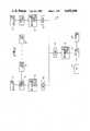
- FIG. 1is a block diagram of the overall system of this invention
- FIG. 2is an expanded block diagram of a remote terminal and transceiver unit, together with associated circuitry, as shown in FIG. 1;
- FIG. 3is a pictorial side view illustrating a miner equipped with a lighting arrangement having portions preferrably utilized in conjunction with this invention
- FIG. 4is a simplified schematic and block diagram illustrating the connection of a miner equipped transponder with the lighting arrangement power cord for use of the cord by the transponder as a transmitting and receiving antenna;
- FIG. 5is a simplified block diagram of the transponder utilized in this invention.
- FIG. 6is an expanded block and schematic diagram of the transponder shown in FIG. 5 utilized in conjunction with a battery pack and power cord in accordance with this invention
- FIG. 7is a simplified block diagram illustrating microprocessor hardware for decoding of a 256 bit location data word
- FIG. 8is an expanded block and schematic diagram illustrating microprocessor hardware for decoding of a 256 bit location data word
- FIG. 9is a block diagram of a modem useful in this invention as shown in FIGS. 1 and 2;
- FIGS. 10 thru 14are flow charts illustrating operation of the transponder utilized in this invention.
- the overall system 19 for locating and/or determining the position of transponder equipped personnel (or other objects)is shown in FIG. 1.
- a plurality of remote terminals 21are utilized, each of which terminals are positioned as deemed necessary or desirable to facilitate locating the transponder equipped personnel.
- remote terminals 21may be positioned at predetermined entrances to different portions of the mine or at predetermined points in the mine shaft. By so locating the remote terminals 21, it is possible to sense the presence of a transponder equipped miner and send information indicative thereof to the surface where a record is established of miner presence and/or location within the mine.
- each remote terminal 21has a sensor array 23 and a transceiver unit 25 connected therewith.
- Each remote terminalin conjunction with sensor array 23 and transceiver unit 25, provides an identifying code with each data word sent from the remote terminal, synchronizes the transponder communicating with the remote terminals through the transceiver units, and causes the remote terminals to send out pulses for interrogation purposes through transceiver units 25.
- Each remote terminal 21is connected through parallel-to-serial communication link 27 to modem 29, with modems 29 being commonly connected to modem 31 which is connected through parallel-to-serial communication link 33 to host computer 35.
- host computer 35is preferrably connected with a CRT display 37 and a line printer 39.
- Remote terminal 21 and transceiver unit 25are shown in greater detail in FIG. 2.
- remote terminal 21includes a sensor interface unit 41 (which preferably includes, as indicated, analog-to-digital and memory circuitry), connected with sensor array 23 and processing unit 43 (which preferably includes a microprocessor memory, random access memory, read only memory, timer and decoder circuitry).
- Processor unit 43is connected through parallel-to-serial communication link 27 to modem 29 which may be typically connected, for example, to a conventional telephone line.
- Transceiver unit 25includes a transmitter and receiver control logic unit 45, the output from which is coupled through transmitter amplifier 47 to antenna 49 from which the transmitted signal is radiated to transponders 53.
- the reply signals from transponders 53are received at antenna 49 and coupled to receiver 51 which is connected with transponder transmitter and receiver control logic unit 45.
- the method by which the system acquires personnel location informationis digital, although not necessarily compatible with any standard coding technique. That is, after each interrogation of a particular terminal location, the terminal hardware forms a 256 bit word containing the information on specific miners in that area at that time. In other words, the location word will be an array of ones and zeros (256 bits) where the ones represent the specific transponder which gave a response upon interrogation.
- This 256 bit wordcan be decoded locally at each terminal before transmitting to the surface or can be transmitted to the surface as a 256 bit location word and decoded at the surface by the host computer.
- the mechanism for decodingneed only be implemented once (at the host computer).
- decoding of the information at each remote terminal into eight bit word identifying each response prior to transmitting this information to the surfaceis advisable. This can be done in microcomputer circuitry at each location and is considered preferrable.
- Each remote terminal 21is able to communicate with host computer 35, and host computer 35 is able to communicate with each remote terminal 21.
- each remote terminal 21includes an identifying code with each data word sent to the host. All transactions from each remote terminal contains only updated data that has changed from the previous transmission. If the digital inputs are unchanged, this is preferably signalled by a particular code (such as, for example, a code 5 and all zeros signifying a "no change" condition). If no new transponder replies are received, this is also preferably signalled by a particular code (such as, for example, a code 9 where all zeros are returned). Keyboard data is buffered by each remote terminal and only complete messages are sent to the host computer 35.
- another code(such as, for example, a code 15) is transmitted by the remote terminal to indicate completion.
- host computer 35the computer responds either by echoing the code to signify that all transactions were completed successfully, sending another code (such as, for example, a code 10), to request a retransmission of some or all remote data, or downloading display information to the remote.
- Remote terminals originating the messagessends all keyboard data to the host computer, and the host computer, in turn retransmits this data as display information to the receiving remote station with a maximum delay of 3.2 seconds.
- the system of this inventionis designed to accomodate an underground work force of up to 256 miners using an 8 bit binary I.D. code.
- Descrimination between simultaneous transmissions from several different transponders in the same vicinityis achieved utilizing time-division multiplexing.
- a single interrogate pulse train from a remote terminalsynchronizes all transponders.
- all transponderstransmit an identical reply code, except the response are timewise spaced, or staggered. This time-division multiplexing arrangement allows simple DIP switch channel selection at the transponders.
- Remote interrogation of a transponderis started by the remote terminal sending out a train of five pulses, each one microsecond wide and two microseconds apart.
- the transponder decoderupon receiving this valid pulse train, begins a delay countdown.
- Each transponderhas a unique delay as its channel I.D.
- poweris applied to the transmitter section and a response code is transmitted twice.
- This response codewill again be a train of five pulses, each 0.5 microseconds wide. The timing just described allows the complete cycle to occur in approximately 15 microseconds, and allowing necessary time for component tolerances, all 256 transponder channels are interrogated in 5 seconds.
- This transponder designincludes easy implementation, identical devices, transmitter power reduced to low power consumption, and fast response, with all support circuitry being CMOS logic.
- a battery pack 55is normally worn by each miner 57 with the battery pack being normally connected by power cord 59 to lamp 61 mounted in the cap of the miner to thus provide a lighting arrangement.
- cord 59provides a transmit and receive antenna with power from battery pack 55 being also utilized to power transponder 53 (which may be built into either the battery or lamp).
- This antenna approach for the transponderis feasible by making the best use of the power cord (which is normally three feet long and connects the cap-lamp to the battery).
- a quarter wave monopole antennawould thus be approximately 1.5 meters which is approximately 4.92 feet.
- an optimum match to the communications circuits for receiving and transmittingis not achieved by use of a 3 foot power cord, but such a cord may nevertheless be successfully utilized in this case (though not optimally utilized).
- transponder 53Connection of transponder 53 to the power cord is shown in FIG. 4.
- the negative terminal of battery 63is connected to one side of capacitor 64 and to negative lead 65 of cord 59
- the positive terminal of battery 63is connected to one side of capacitor 66 and to positive lead 67 of cord 59.
- the other side of capacitors 64 and 66are connected with the junction therebetween being connected to transmitter 69 and receiver 71, with the connection to transmitter 69 being through analog switch 72 (preferrably a Harris H15040). Switch 72 momentarily switches transmitter 69 into the circuit when a reply response is called for by receiver 71.
- analog switch 72preferrably a Harris H15040
- the transponderis also powered from cap-lamp battery pack 55. This is preferably accomplished by connecting the transponder to the power lead so that the transponder is "on" whenever the cap-lamp is “on”.
- the transponder current drainis only a small fraction of the lamp current drain, so that even when the transponder is not in use, the current drain impact of leaving it energized is negligible.
- the main disadvantage of such an arrangementis that the transponder is not self-contained and must be interfaced with an existing peice of commercial equipment to function properly.
- FIG. 5is a block diagram of transponder 53 showing the functional logic thereof.
- the incoming signalis received at antenna 73 and coupled to R.F. demodulator 75, the output from whch is coupled to decoder 77 where an enable signal output is provided that is coupled to a divide-by-640 unit 79 which provides a 19.5 microsecond output signal.
- This outputis coupled through delay counter 81 and DIP switch channel coding unit 83 to transmitter timing logic unit 85.
- the output from transmitter timing logic unit 85is coupled to encoder 87 which produces an output signal that is coupled through R.F. amplifier 89 to antenna 73 to be transmitted as a reply signal from the transponder.
- this reply signalis timewise delayed by a predetermined time delay so that the reply signal is transmitted within a predetermined time window and thus is distinguished from replies from other transponders that might be replying to the interrogation signal from the remote terminal.
- FIG. 6is an expanded block and schematic diagram of transponder 53, shown in conjunction with miner equipped power and lamp circuitry.
- the positive terminal of battery 63(of battery pack 55 normally carried by the miner) is connected to cap-lamp 61 through lead 67.
- lead 67is provided with filters at opposite end portions to establish an active portion of the antenna. More particularly, the positive terminal of battery 63 is connected to one side of parallel connected capacitor 91 and resistors 92 and 93, while one side of cap-lamp 61 is connected to one side of parallel connected capacitor 95 and resistors 96 and 97 with the active portion of the antenna being provided by that portion of lead 67 existing between the filters.
- the negative (grounded) side of battery 63is connected to cap-lamp 61 through lead 65 which also includes a pair of filters one of which is formed by parallel connected capacitor 99 and resistors 100 and 101, and the other of which is formed by parallel connected capacitor 103 and resistors 104 and 105.
- the power cordas both the transmitting and receiving antenna, while not optimum, utilizes equipment normally carried by the miner. Since this cord must carry the D.C. to the cap-lamp, the RF signal to be transmitted and received is isolated from the remainder of the circuitry by use of the filters at each end of the cord.
- the filtersare parallel resonant traps selected for the frequency band to be utilized for the transmitted and received signals. In this case, use of a 49 MHz center frequency with a Q factor of the traps of about 5 results in a band width of 9.8 MHz centered about the 49 MHz center frequency is preferred.
- Both sides of the cordare excited with an RF signal which is preferred to exciting only one side since the cable could have 20 pf of shunt capacitance per foot which would severely load the active wire.
- the thus formed antennais connected to transponder 53, and more particularly, the portions of lead 65 and 67 extending between the filter are connected through capacitor 64 and 66, respectively, to the transmitter and receiver units of the transponder.
- an antenna switchis utilized to keep RF out of the receiver while transmitting and to prevent the transmitter output circuit from absorbing signals during reception.
- This antenna switchis achieved, as shown in FIG. 6, by use of a diode switch arrangement. As shown, the antenna is connected through diode 111 and capacitor 113 to transmitter module 115, and through quarter wave matching network 117 to diode 119 to the receiver module circuitry.
- the diode switchoperates as follows: during transmit, both diodes 111 and 119 are forwardly biased by current through RF choke 120 so that diode 111 connects transmitter module 115 to the antenna and diode 119 places an RF short across the receiver module input, (which short reflects through quarter wave matching network 117 to provide an "open" at the point where power would otherwise flow from the antenna to the receiver). 30 db or more isolation is preferable in this switch. All diodes are hot-carrier type and all capacitors are large volume chip type. The quarter wave matching network has an impedance that matches the receiver input and antenna circuits.
- transmitter module 115While a National LM 1871 transmitter could be utilized for transmitter module 115, this would require a 6 volt source (and thus not be directly usable with a normal 4 volt cap-lamp battery 63). Such use would therefore require a DC to DC converter. Hence, it is preferred to use a transmitter module which directly requires only a 4 volt power supply in order to use cap-lamp battery 63.
- quarter wave matching network 117is connected to one side of capacitors 121 and 122, the opposite sides of which are connected to the primary winding of transformer 124.
- the secondary winding of transformer 124has a diode 125 connected thereacross, is connected to pins 4 and 5 of receiver module 126, and is connected with pin 3 and ground through a capacitor 127.
- Power from the transponderis supplied from battery 63 through resistor 128 to transmitter module 115 and to pin 6 of receiver module 126 (with capacitors 129 and 130 to ground being also connected to the positive voltage line.
- the positive power lineis also connected through parallel connected capacitor 131 and inductor 132 to crystal 133, with the junction of resistor 128 and capacitor 131 having a capacitor 135 to ground connected therewith.
- Pin 18 of receiver module 126is connected to one side of parallel connected capacitor 137 and inductor 138, the other side of which is connected through resistor 139 to the positive power line and to ground through resistor 140.
- the positive power lineis also connected through resistor 142 to pin 13 of receiver module 126 and with ground through capacitor 143.
- Pin 15 of receiver module 126is connected with the center tap of inductor 146, which inductor has a capacitor 145 connected thereacross and one side connected with ground through capacitor 147.
- pin 16 of receiver module 126is connected with ground through capacitor 149.
- Microprocessor timer 151is connected at pin 21 to inductor 120 (for keying the transmitter module off and on), at pin 20 to pin 13 of receiver module 126 (to receive the input from the receiver module), and at pins 2 and 3 to opposite sides of crystal 153 (32.768 KHz which allows a 244 microsecond instruction cycle time).
- Resistors 154 and 155are connected in series with one another and connected in parallel with crystal 153 with the opposite ends of resistor 154 being connected with ground through capacitors 156 and 157.
- DIP switch 159has eight switching elements for use in selecting 1 of 256 addresses. Each switching element is connected with a different pin of microprocessor timer 151 so that the switch can be read by the microprocessor timer, with each connection having one side of a resistor (resistors 161-168) connected therewith with the resistors being connected in common at the other side to the positive power line and to one side of parallel connected resistor 170 and diode 171 (the other side of which is connected with pin 4 of microprocessor timer 151 and with ground through capacitor 172).
- resistorresistor
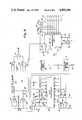
- FIG. 7is a simplified block diagram illustrating microprocessor hardware that is used in all of the remote terminals 21.
- the output of 256 bit shift pulse generator 180is coupled to 8 bit counter 182 and to coincidence detector 184, which detector also receives the data stream from the receiver output.
- the output from coincidence detector 184is a latch pulse which is coupled to buffer register 186 (connected with memory 188) and to 8 bit shift pulse generator 190, with generator 190 providing a shift input to buffer register 186.
- FIG. 8is an expanded block diagram illustrating microprocessor hardware that is used in each remote terminal to decode the 256 bit location data word.
- a 256 bit shift pulse generator 180provides a pulse train to 8 bit counter 182 and to coincidence detector 184.
- the output from 8 bit counter 182are coupled to buffer register, or parallel/serial unit 186, which register supplies an output to microprocessor memory unit 188 and receives inputs from 8 bit shift pulse generator 190 and coincidence detector 184.
- 256 bit shift pulse generator 180includes an integrated circuit 192 connected with a 5 volt power supply through resistor 194 having a capacitor 196 to ground connected therewith.
- Coincidence detector 184includes a pair of NAND gates 198 and 200, while 8 bit shift pulse generator 190 includes a control flip-flop 202 the reset output of which is coupled to integrated circuit 204.
- the output of NAND gate 198is coupled to NAND gate 206, which receives a second input from NAND gate 208 connected with control flip-flop 202, and supplies an output to parallel/serial unit 186 (latch input).
- the output from control flip-flop 202provides a P/S control input to parallel/serial unit 186.
- FIG. 9illustrates a typical modem that can be utilized in the invention.
- the input from the communication linkis coupled to I/O expander 212 which is connected with dual BCD counters 214 and 216.
- the free running pulse frequency inputis converted to a calibrated digital output.
- FIGS. 10 through 14are flow charts to illustrate the invention.
- a simplified flow chart for transponder general operationis shown on FIG. 10. Details of a valid integration of the transponder is shown in FIGS. 11 and 12 with coding therefore being as follows:
- Coding for a 4 microsecond weight subroutineis as follows:
- Coding for a 4 microsecond weight subroutineis as follows:
- this inventionprovides an improved monitoring and/or locating system that is particularly well suited for use in conjunction with monitoring miners in an underground mine.
Landscapes
- Engineering & Computer Science (AREA)
- Physics & Mathematics (AREA)
- General Physics & Mathematics (AREA)
- Theoretical Computer Science (AREA)
- Business, Economics & Management (AREA)
- Mining & Mineral Resources (AREA)
- Toxicology (AREA)
- Economics (AREA)
- Health & Medical Sciences (AREA)
- Tourism & Hospitality (AREA)
- Development Economics (AREA)
- Operations Research (AREA)
- Quality & Reliability (AREA)
- Strategic Management (AREA)
- Human Resources & Organizations (AREA)
- General Business, Economics & Management (AREA)
- Computer Networks & Wireless Communication (AREA)
- Entrepreneurship & Innovation (AREA)
- Marketing (AREA)
- Electromagnetism (AREA)
- General Health & Medical Sciences (AREA)
- Artificial Intelligence (AREA)
- Computer Vision & Pattern Recognition (AREA)
- General Engineering & Computer Science (AREA)
- Life Sciences & Earth Sciences (AREA)
- General Life Sciences & Earth Sciences (AREA)
- Geochemistry & Mineralogy (AREA)
- Geology (AREA)
- Selective Calling Equipment (AREA)
Abstract
Description
This invention relates to an object monitoring and locating system, and, more particularly, relates to a system for locating and monitoring underground miners.
It is often times necessary, or at least desirable, that the location of objects, including personnel, be known or at least be determinable. This is particularly true, for example, in the case of underground miners.
While various attempts have been made to monitor the position of objects, including personnel, and/or to provide an indication of location, such attempts have not been heretofore completely satisfactory due at least in part to the problems associated with underground mines, the necessity of not unduly burdening the miner and/or providing a relatively simple yet dependable system.
With respect to the prior art patents, various systems have been heretofore suggested for identification of personnel or other objects (see, for example, U.S. Pat. Nos. 4,209,783; 4,223,830; and 4,242,663) and for surveilance of particular areas (see, for example, U.S. Pat. Nos. 3,257,653; 4,095,211; and 4,229,737). In addition, it has heretofore been suggested that a coded signal could be transmitted to a plurality of remote transceivers for activating transponders when a unique code was received by the transponder (see U.S. Pat. No. 3,805,265). Also, it has heretofore been suggested that a pair of pulses can be transmitted to activate a transponder depending upon a preselected spacing between pulses (see U.S. Pat. No. 3,226,680).
This invention provides a relatively simple yet dependable system for monitoring and/or locating objects, including personnel, that is particularly useful in a mine environment and which does not require burdening of the miner with undue extra equipment.
It is therefore an object of this invention to provide an improved object monitoring system.
It is another object of this invention to provide an improved personnel locating system that is particularly useful in monitoring underground miners.
It is still another object of this invention to provide an improved object monitoring system that is relatively simple yet dependable.
It is still another object of this invention to provide an improved object monitoring system that utilizes transponders associated with the monitored object.
It is yet another object of this invention to provide an improved personnel locating system that does not unduly burden the using personnel.
It is still another object of this invention to provide an improved mine personnel locating system that utilizes the power supply and power cord associated with the lamp of a miner in conjunction with a transponder.
It is yet another object of this invention to provide an improved personnel locating system that utilizes transponders and a time division multiplexing arrangement.
With these and other objects in view, which will become apparent to one skilled in the art as the description proceeds, this invention resides in the novel construction, combination, and arrangement of parts substantially as hereinafter described and more particularly defined by the appended claims, it being understood that such changes in the precise embodiment of the herein disclosed invention are meant to be included as come within the scope of the claims.
The accompanying drawings illustrate a complete embodiment of the invention according to the best mode so far devised for the practical application of the principles thereof, and in which:
FIG. 1 is a block diagram of the overall system of this invention;
FIG. 2 is an expanded block diagram of a remote terminal and transceiver unit, together with associated circuitry, as shown in FIG. 1;
FIG. 3 is a pictorial side view illustrating a miner equipped with a lighting arrangement having portions preferrably utilized in conjunction with this invention;
FIG. 4 is a simplified schematic and block diagram illustrating the connection of a miner equipped transponder with the lighting arrangement power cord for use of the cord by the transponder as a transmitting and receiving antenna;
FIG. 5 is a simplified block diagram of the transponder utilized in this invention;
FIG. 6 is an expanded block and schematic diagram of the transponder shown in FIG. 5 utilized in conjunction with a battery pack and power cord in accordance with this invention;
FIG. 7 is a simplified block diagram illustrating microprocessor hardware for decoding of a 256 bit location data word;
FIG. 8 is an expanded block and schematic diagram illustrating microprocessor hardware for decoding of a 256 bit location data word;
FIG. 9 is a block diagram of a modem useful in this invention as shown in FIGS. 1 and 2; and
FIGS. 10thru 14 are flow charts illustrating operation of the transponder utilized in this invention.
Theoverall system 19 for locating and/or determining the position of transponder equipped personnel (or other objects) is shown in FIG. 1. As shown, a plurality ofremote terminals 21 are utilized, each of which terminals are positioned as deemed necessary or desirable to facilitate locating the transponder equipped personnel. For use in mines, for example,remote terminals 21 may be positioned at predetermined entrances to different portions of the mine or at predetermined points in the mine shaft. By so locating theremote terminals 21, it is possible to sense the presence of a transponder equipped miner and send information indicative thereof to the surface where a record is established of miner presence and/or location within the mine.
As shown in FIG. 1, eachremote terminal 21 has asensor array 23 and atransceiver unit 25 connected therewith. Each remote terminal, in conjunction withsensor array 23 andtransceiver unit 25, provides an identifying code with each data word sent from the remote terminal, synchronizes the transponder communicating with the remote terminals through the transceiver units, and causes the remote terminals to send out pulses for interrogation purposes throughtransceiver units 25.
Eachremote terminal 21 is connected through parallel-to-serial communication link 27 tomodem 29, withmodems 29 being commonly connected tomodem 31 which is connected through parallel-to-serial communication link 33 to hostcomputer 35. As indicated in FIG. 1,host computer 35 is preferrably connected with aCRT display 37 and aline printer 39.
The method by which the system acquires personnel location information is digital, although not necessarily compatible with any standard coding technique. That is, after each interrogation of a particular terminal location, the terminal hardware forms a 256 bit word containing the information on specific miners in that area at that time. In other words, the location word will be an array of ones and zeros (256 bits) where the ones represent the specific transponder which gave a response upon interrogation.
This 256 bit word can be decoded locally at each terminal before transmitting to the surface or can be transmitted to the surface as a 256 bit location word and decoded at the surface by the host computer. By decoding at the surface, the mechanism for decoding need only be implemented once (at the host computer). However, where the nonstandard format of the 256 bit word upsets the data protocol to the extent that it would require more effort in the terminal hardware and software to design around it, then decoding of the information at each remote terminal into eight bit word identifying each response prior to transmitting this information to the surface is advisable. This can be done in microcomputer circuitry at each location and is considered preferrable.
Eachremote terminal 21 is able to communicate withhost computer 35, andhost computer 35 is able to communicate with eachremote terminal 21. In order to differentiate between remote terminals, eachremote terminal 21 includes an identifying code with each data word sent to the host. All transactions from each remote terminal contains only updated data that has changed from the previous transmission. If the digital inputs are unchanged, this is preferably signalled by a particular code (such as, for example, acode 5 and all zeros signifying a "no change" condition). If no new transponder replies are received, this is also preferably signalled by a particular code (such as, for example, acode 9 where all zeros are returned). Keyboard data is buffered by each remote terminal and only complete messages are sent to thehost computer 35. Upon completion of a message fromremote terminal 21, another code (such as, for example, a code 15) is transmitted by the remote terminal to indicate completion. Upon receipt byhost computer 35 the computer responds either by echoing the code to signify that all transactions were completed successfully, sending another code (such as, for example, a code 10), to request a retransmission of some or all remote data, or downloading display information to the remote.
To utilizing miners, system operation appears to allow direct communication between remote terminals. Remote terminals originating the messages sends all keyboard data to the host computer, and the host computer, in turn retransmits this data as display information to the receiving remote station with a maximum delay of 3.2 seconds.
A larger mine having, for example, 15 working sections with 15 men per section, will have a total underground work force of 225 men. The system of this invention is designed to accomodate an underground work force of up to 256 miners using an 8 bit binary I.D. code. Descrimination between simultaneous transmissions from several different transponders in the same vicinity is achieved utilizing time-division multiplexing. A single interrogate pulse train from a remote terminal synchronizes all transponders. In turn, all transponders transmit an identical reply code, except the response are timewise spaced, or staggered. This time-division multiplexing arrangement allows simple DIP switch channel selection at the transponders.
Remote interrogation of a transponder is started by the remote terminal sending out a train of five pulses, each one microsecond wide and two microseconds apart. The transponder decoder, upon receiving this valid pulse train, begins a delay countdown. Each transponder has a unique delay as its channel I.D. Upon completion of the delay, power is applied to the transmitter section and a response code is transmitted twice. This response code will again be a train of five pulses, each 0.5 microseconds wide. The timing just described allows the complete cycle to occur in approximately 15 microseconds, and allowing necessary time for component tolerances, all 256 transponder channels are interrogated in 5 seconds.
This transponder design includes easy implementation, identical devices, transmitter power reduced to low power consumption, and fast response, with all support circuitry being CMOS logic.
As indicated in FIG. 3, abattery pack 55 is normally worn by eachminer 57 with the battery pack being normally connected bypower cord 59 tolamp 61 mounted in the cap of the miner to thus provide a lighting arrangement. For use in this invention,cord 59 provides a transmit and receive antenna with power frombattery pack 55 being also utilized to power transponder 53 (which may be built into either the battery or lamp).
This antenna approach for the transponder is feasible by making the best use of the power cord (which is normally three feet long and connects the cap-lamp to the battery). However, the wave length of R.F. transmission is λ=c/f where λ is wavelength is meters, c is the speed of light (3×10⁸ m/sec), and f is the frequency in Hz, at f=MHz, λ=approximately 6.1 meters. A quarter wave monopole antenna would thus be approximately 1.5 meters which is approximately 4.92 feet. Thus, an optimum match to the communications circuits for receiving and transmitting is not achieved by use of a 3 foot power cord, but such a cord may nevertheless be successfully utilized in this case (though not optimally utilized).
Connection of transponder 53 to the power cord is shown in FIG. 4. As shown, the negative terminal ofbattery 63 is connected to one side ofcapacitor 64 and tonegative lead 65 ofcord 59, while the positive terminal ofbattery 63 is connected to one side ofcapacitor 66 and topositive lead 67 ofcord 59. For antenna purposes, the other side ofcapacitors transmitter 69 and receiver 71, with the connection totransmitter 69 being through analog switch 72 (preferrably a Harris H15040).Switch 72 momentarily switchestransmitter 69 into the circuit when a reply response is called for by receiver 71.
The transponder is also powered from cap-lamp battery pack 55. This is preferably accomplished by connecting the transponder to the power lead so that the transponder is "on" whenever the cap-lamp is "on".
The transponder current drain is only a small fraction of the lamp current drain, so that even when the transponder is not in use, the current drain impact of leaving it energized is negligible. There are several significant advantages in powering the transponder by means of the cap-lamp battery pack, including ensuring that the batteries will be up whenever the miner goes underground (since it is a well established routine for miners to charge their cap-lamp batteries daily) and minimizing the possibility of the transponder being left on inadvertantly over a long period of time. The main disadvantage of such an arrangement is that the transponder is not self-contained and must be interfaced with an existing peice of commercial equipment to function properly.
FIG. 5 is a block diagram of transponder 53 showing the functional logic thereof. As shown, the incoming signal is received at antenna 73 and coupled to R.F. demodulator 75, the output from whch is coupled to decoder 77 where an enable signal output is provided that is coupled to a divide-by-640 unit 79 which provides a 19.5 microsecond output signal. This output is coupled through delay counter 81 and DIP switch channel coding unit 83 to transmittertiming logic unit 85. The output from transmittertiming logic unit 85 is coupled toencoder 87 which produces an output signal that is coupled through R.F.amplifier 89 to antenna 73 to be transmitted as a reply signal from the transponder. As brought out hereinabove, this reply signal is timewise delayed by a predetermined time delay so that the reply signal is transmitted within a predetermined time window and thus is distinguished from replies from other transponders that might be replying to the interrogation signal from the remote terminal.
FIG. 6 is an expanded block and schematic diagram of transponder 53, shown in conjunction with miner equipped power and lamp circuitry. As brought out hereinabove, the positive terminal of battery 63 (ofbattery pack 55 normally carried by the miner) is connected to cap-lamp 61 throughlead 67. As shown in FIG. 6, lead 67 is provided with filters at opposite end portions to establish an active portion of the antenna. More particularly, the positive terminal ofbattery 63 is connected to one side of parallel connected capacitor 91 andresistors 92 and 93, while one side of cap-lamp 61 is connected to one side of parallelconnected capacitor 95 andresistors lead 67 existing between the filters. In like manner, the negative (grounded) side ofbattery 63 is connected to cap-lamp 61 throughlead 65 which also includes a pair of filters one of which is formed by parallelconnected capacitor 99 andresistors resistors 104 and 105.
Use of the power cord as both the transmitting and receiving antenna, while not optimum, utilizes equipment normally carried by the miner. Since this cord must carry the D.C. to the cap-lamp, the RF signal to be transmitted and received is isolated from the remainder of the circuitry by use of the filters at each end of the cord. The filters are parallel resonant traps selected for the frequency band to be utilized for the transmitted and received signals. In this case, use of a 49 MHz center frequency with a Q factor of the traps of about 5 results in a band width of 9.8 MHz centered about the 49 MHz center frequency is preferred.
Both sides of the cord are excited with an RF signal which is preferred to exciting only one side since the cable could have 20 pf of shunt capacitance per foot which would severely load the active wire.
The thus formed antenna is connected to transponder 53, and more particularly, the portions oflead capacitor
For use of the antenna for both transmitting and receiving, an antenna switch is utilized to keep RF out of the receiver while transmitting and to prevent the transmitter output circuit from absorbing signals during reception. This antenna switch is achieved, as shown in FIG. 6, by use of a diode switch arrangement. As shown, the antenna is connected throughdiode 111 andcapacitor 113 to transmitter module 115, and through quarterwave matching network 117 todiode 119 to the receiver module circuitry.
The diode switch operates as follows: during transmit, bothdiodes RF choke 120 so thatdiode 111 connects transmitter module 115 to the antenna anddiode 119 places an RF short across the receiver module input, (which short reflects through quarterwave matching network 117 to provide an "open" at the point where power would otherwise flow from the antenna to the receiver). 30 db or more isolation is preferable in this switch. All diodes are hot-carrier type and all capacitors are large volume chip type. The quarter wave matching network has an impedance that matches the receiver input and antenna circuits.
While a National LM 1871 transmitter could be utilized for transmitter module 115, this would require a 6 volt source (and thus not be directly usable with a normal 4 volt cap-lamp battery 63). Such use would therefore require a DC to DC converter. Hence, it is preferred to use a transmitter module which directly requires only a 4 volt power supply in order to use cap-lamp battery 63.
As shown in FIG. 6, quarterwave matching network 117 is connected to one side ofcapacitors transformer 124. The secondary winding oftransformer 124 has adiode 125 connected thereacross, is connected topins receiver module 126, and is connected withpin 3 and ground through acapacitor 127.
Power from the transponder is supplied frombattery 63 throughresistor 128 to transmitter module 115 and to pin 6 of receiver module 126 (withcapacitors connected capacitor 131 andinductor 132 tocrystal 133, with the junction ofresistor 128 andcapacitor 131 having acapacitor 135 to ground connected therewith.
FIG. 7 is a simplified block diagram illustrating microprocessor hardware that is used in all of theremote terminals 21. As shown in FIG. 7, the output of 256 bitshift pulse generator 180 is coupled to 8bit counter 182 and tocoincidence detector 184, which detector also receives the data stream from the receiver output. The output fromcoincidence detector 184 is a latch pulse which is coupled to buffer register 186 (connected with memory 188) and to 8 bitshift pulse generator 190, withgenerator 190 providing a shift input to buffer register 186.
FIG. 8 is an expanded block diagram illustrating microprocessor hardware that is used in each remote terminal to decode the 256 bit location data word. As shown, a 256 bitshift pulse generator 180 provides a pulse train to 8bit counter 182 and tocoincidence detector 184. The output from 8bit counter 182 are coupled to buffer register, or parallel/serial unit 186, which register supplies an output tomicroprocessor memory unit 188 and receives inputs from 8 bitshift pulse generator 190 andcoincidence detector 184.
As shown in FIG. 8, 256 bitshift pulse generator 180 includes anintegrated circuit 192 connected with a 5 volt power supply throughresistor 194 having acapacitor 196 to ground connected therewith.Coincidence detector 184 includes a pair ofNAND gates shift pulse generator 190 includes a control flip-flop 202 the reset output of which is coupled tointegrated circuit 204. The output ofNAND gate 198 is coupled toNAND gate 206, which receives a second input from NAND gate 208 connected with control flip-flop 202, and supplies an output to parallel/serial unit 186 (latch input). As shown, the output from control flip-flop 202 provides a P/S control input to parallel/serial unit 186.
FIG. 9 illustrates a typical modem that can be utilized in the invention. As shown, the input from the communication link is coupled to I/O expander 212 which is connected with dual BCD counters 214 and 216. By this arragement, the free running pulse frequency input is converted to a calibrated digital output.
FIGS. 10 through 14 are flow charts to illustrate the invention. A simplified flow chart for transponder general operation is shown on FIG. 10. Details of a valid integration of the transponder is shown in FIGS. 11 and 12 with coding therefore being as follows:
______________________________________ CODING FOR VALID INTERROGATE ADDRESS INSTRUCTION OP. CODE ______________________________________ 000CLRA 00 001LBI 0 33 002 -- 80 003STII 0 70 004STII 0 70 005LBI 0,1 33 006 -- 81 007SMB 3 4B 008ING 33 009 --2A 00A SKE 2100B JP 7 C700C JSR WAIT 4 60 00D --B0 00E ING 33 00F -- 2A 010SKE 21 001JP 7 C7 002JSR WAIT 4 60 003 -- B0 004RMB 3 43 005ING 33 006 -- 2A 007SKE 21 008 JP C7 009JSR WAIT 4 60 00A --B0 00B SMB 34B 00C ING 33 00D --2A 00E SKE 2100F JP 7 C7 020JSR WAIT 4 60 021 -- B0 022ING 33 023 -- 2A 024SKE 21 025JP 7 C7 026JSR WAIT 4 6B 027 -- 00 028RMB 3 43 029ING 33 02A --2A 02B SKE 2102C JP 7 C7 02D JMP 40 60 02E -- 40 ______________________________________
Coding for a 4 microsecond weight subroutine is as follows:
______________________________________ CODING FOR 4 MS WAIT SUBROUTINE ADDRESS INSTRUCTION OP. CODE ______________________________________ 0C0 NOP 44 0C1 NOP 44 0C3 NOP 44 0C4 NOP 44 0C5 NOP 44 0C6 NOP 44 0C7 NOP 44 0C8 NOP 44 0C9 NOP 44 0CA NOP 44 0CB NOP 44 0CC NOP 44 0CD NOP 44 0CE NOP 44 0CF NOP 44 0D0 NOP 44 0D1 RET 48 ______________________________________
Details for read and countdown are shown in FIG. 13, with coding therefore being as follows:
______________________________________ CODING FOR READ & COUNTDOWN ADDRESS INSTRUCTION OP. CODE ______________________________________ 0400,2 33 041 -- 82 042 LBI INL 33 043 -- 2E 0440,0 33 045 -- 80 046 LBI SKE 21 047 JP C9 048 JP D0 049 COMP 40 04A AISC 1 51 04B NOP 44 04C COMP 4004D JSR WAIT 20 69 04E -- 00 04F JP C6 0500,2 23 051 -- 82 052 XAD SKE 21 053 JP D5 054 JMP 80 60 055 -- 80 056 COMP 40 057 AISC 1 51 058 NOP 44 059 COMP 4005A JSR WAIT 20 69 05B -- 000,2 23 05D -- 82 05E COMP 40 05F JP C6 ______________________________________ 05C XAD
Coding for a 4 microsecond weight subroutine is as follows:
______________________________________ CODING FOR 20 MS WAIT SUBROUTINE ADDRESS INSTRUCTION OP. CODE ______________________________________ 100 NOP 44 NOP 44 ↓ ↓ ↓ 14F NOP 44 150 RET 48 ______________________________________
Details for a transmit sequence is shown in FIG. 14, with coding therefore being as follows:
______________________________________ CODING FOR XMIT SEQUENCE ADDRESS INSTRUCTION OP. CODE ______________________________________ 080 RC 32 081CLRA 00 082AISC 8 58 083 CAB 50 084OBD 33 085 -- 3E 086JSR WAIT 4 6B 087 -- 00 088CLRA 00 089 CAB 5008A OBD 33 08B -- 3E08C JSR WAIT 4 6B 08D -- 0008E AISC 8 58 08F CAB 50 090OBD 33 091 -- 3E 092JSR WAIT 4 6B 093 -- 00 094CLRA 00 095 CAB 50 096OBD 33 097 -- 3E 098JMP 7 60 099 -- 07 ______________________________________
From the foregoing, it should be apparent that this invention provides an improved monitoring and/or locating system that is particularly well suited for use in conjunction with monitoring miners in an underground mine.
Claims (25)
1. A system for monitoring a plurality of movable objects within a preselected area, said system comprising:
a plurality of transmitting means at said preselected area;
control means connected with said plurality of transmitting means to cause each of said plurality of transmitting means to provide an interrogation pulse output at predetermined times;
a plurality of transponder means each of which is associated with and constrained to movement with a different one of said movable objects, with said plurality of transponder means being capable of simultaneously receiving said interrogation pulse output from said plurality of transmitting means, and with each of said transponder means, responsive to receipt of said interrogation pulse output from said transmitting means, providing a reply output with said reply output from each of said transponder means being delayed by different predetermined time intervals so that all reply outputs from said transponder means occur at different time intervals with respect to one another; and
signal processing means for providing an output indicative of the particular transponder means from which a reply output was received to thereby enable monitoring of the objects associated with said transponder means.
2. The system of claim 1 wherein said system includes central processing means connected with each of said transmitting means.
3. The system of claim 1 wherein each of said transponder means includes delay means for delaying said reply output for a predetermined period of time upon receipt of said interrogation output from said transmitting means to thereby establish said different predetermined time intervals.
4. The system of claim 1 wherein said signal processing means includes receiving means includes a plurality of receivers at predetermined spaced positions within said preselected area.
5. The system of claim 4 wherein said signal processing means also includes decoding means includes central processing means connected with each of said receivers.
6. The system of claim 1 wherein said signal processing means includes decoding means includes means for sensing the time interval between said interrogation output from said transmitting means and receipt of said reply output from said transponder means and responsive thereto determining the particular transponder means from which said reply output was received.
7. The system of claim 1 wherein said plurality of transmitting means are positioned within a mine, and wherein said monitored objects are underground miners each of which is equipped with a transponder means.
8. A system for monitoring a plurality of underground miners within a mine, said system comprising:
transmitting means positioned within said mine and providing an interrogation output;
a plurality of transponder means each of which is associated with and constrained to movement with a different one of said underground miners, with each of said transponder means, responsive to receipt of said interrogation output from said transmitting means, providing a reply output with said reply output from each of said transponder means occurring at different time intervals with respect to one another, said miners being equipped with lighting means including a power cord, and wherein said transponder means are connected with said power cord whereby said power cord provides a transmitting and receiving antenna for said transponder means;
receiving means at said predetermined area for receiving said reply outputs from said transponder means; and
decoding means connected with said transmitting means and said receiving means for decoding said reply outputs received from said transponder means and, responsive thereto, providing an indication of said movable objects associated with said replying transponder means.
9. The system of claim 8 wherein said system includes RF filters electrically connected on said power cord to establish the effective length of said antenna.
10. The system of claim 8 wherein said power cord extends between battery means and a lamp, and wherein said transponder means is connected with said battery means for powering said transponder means.
11. A system for monitoring a plurality of movable objects within a preselected area, said system comprising:
a plurality of remote terminals at said preselected area;
a plurality of transceiver units each of which is connected with a different one of said remote terminals with each of said transceiver units providing an interrogation output at predetermined times and for receiving reply outputs responsive thereto;
computer means;
communication link means connecting said remote terminals with said computer means;
a plurality of transponders each of which is associated with a different one of said objects to be monitored, each of said transponders having means for receiving said interrogation output from said transceiver units and responsive thereto providing reply outputs with the reply output from each of said transponders being delayed by different predetermined time intervals so that all reply outputs from said transponders are timewise spaced with respect to one another; and
signal processing means for providing an output indicative of the particular transponder from which a reply output was received to thereby enable monitoring of the objects associated with said transponders.
12. The system of claim 11 wherein said system includes means for receiving said indications from said signal processing means and responsive thereto establishing and maintaining the location of said monitored objects.
13. The system of claim 12 wherein said communication link means includes a plurality of first parallel-to-serial communication links each of which is connected with a different one of said remote terminals, modem means connected with said first parallel-to-serial communication links, and a second parallel-to-serial communication link connected with said modem means.
14. The system of claim 11 wherein said monitored objects are underground miners.
15. The system of claim 11 wherein said system includes sensor array means connected with each of said remote terminals.
16. The system of claim 14 wherein said monitored miners have a lamp powered by a battery connected with said lamp through a power cord, and wherein each said transponder is connected with said power cord so that said power cord acts as an antenna for each said transponder.
17. The system of claim 16 wherein said power cord has an RF filter at opposite end portions thereof to determine the effective length of said antenna.
18. The system of claim 16 wherein said transponder is connected with said battery for powering said transponder by said battery.
19. The system of claim 11 wherein each of said transponders includes a microprocessor timer for establishing said time delay for said reply output.
20. The system of claim 19 wherein each of said transponders includes switching means connected with said microprocessor timer for establishing said time delay for said reply output.
21. A system for monitoring underground miners, said system comprising:
a plurality of remote terminals within a mine;
a plurality of transceiver units each of which is connected with a different one of said remote terminals with each of said transceiver units providing an interrogation output at predetermined times;
a plurality of first "parallel-to-serial" communication links each of which is connected with a different one of said remote terminals;
modem means connected with said first parallel-to-serial communication links;
a second parallel-to-serial communication link connected with said modem means;
computer means connected with said second parallel-to-serial communication link;
a plurality of transponders each of which is carried by a different miner to be monitored, with each of said transponders including means for receiving said interrogation output from said transceiver units and responsive thereto providing reply outputs with the reply output from each of said transponders being delayed by different predetermined time intervals so that all reply outputs from said transponders are timewise spaced with respect to one another; and
signal processing means connected with said transceiver means for providing an output indicative of the particular transponder from which a reply output was received to thereby enable monitoring of transponder equipped miners.
22. The system of claim 21 wherein said signal processing means includes means for providing an 8 bit digital output signal indicative of the particular transponder from which said reply output was received.
23. The system of claim 22 wherein said signal processing means includes means for handling 256 bits.
24. The system of claim 21 wherein each of said miners is equipped with a cap-lamp powered by a battery connected with said lamp through a power cord, and wherein said transponder is connected with said power cord so that said power cord serves as the antenna for said transponder, said power cord having RF filters thereon to establish the effective length of said antenna.
25. The system of claim 24 wherein said battery is connected with said transponder to power the same.
Priority Applications (1)
| Application Number | Priority Date | Filing Date | Title |
|---|---|---|---|
| US06/330,976US4495496A (en) | 1981-12-15 | 1981-12-15 | Personnel monitoring and locating system |
Applications Claiming Priority (1)
| Application Number | Priority Date | Filing Date | Title |
|---|---|---|---|
| US06/330,976US4495496A (en) | 1981-12-15 | 1981-12-15 | Personnel monitoring and locating system |
Publications (1)
| Publication Number | Publication Date |
|---|---|
| US4495496Atrue US4495496A (en) | 1985-01-22 |
Family
ID=23292111
Family Applications (1)
| Application Number | Title | Priority Date | Filing Date |
|---|---|---|---|
| US06/330,976Expired - Fee RelatedUS4495496A (en) | 1981-12-15 | 1981-12-15 | Personnel monitoring and locating system |
Country Status (1)
| Country | Link |
|---|---|
| US (1) | US4495496A (en) |
Cited By (131)
| Publication number | Priority date | Publication date | Assignee | Title |
|---|---|---|---|---|
| US4626904A (en)* | 1985-11-12 | 1986-12-02 | Control Data Corporation | Meter for passively logging the presence and identity of TV viewers |
| US4694421A (en)* | 1983-06-29 | 1987-09-15 | Canon Denshi Kabushiki Kaishsa | Interface system which selectively provides impedance matching between a host computer and a control circuit |
| FR2598873A1 (en)* | 1986-05-15 | 1987-11-20 | Banyaszati Fejlesztesi Intezet | CIRCUIT DEVICE FOR THE AUTOMATIC IDENTIFICATION OF LIVES AND OBJECTS |
| US4740788A (en)* | 1986-10-06 | 1988-04-26 | Konneker Lloyd K | Method of providing location dependent visitor dispatching service |
| US4747120A (en)* | 1985-08-13 | 1988-05-24 | Digital Products Corporation | Automatic personnel monitoring system |
| US4837851A (en)* | 1987-08-28 | 1989-06-06 | Weinblatt Lee S | Monitoring technique for determining what location within a predetermined area is being viewed by a person |
| US4930011A (en)* | 1988-08-02 | 1990-05-29 | A. C. Nielsen Company | Method and apparatus for identifying individual members of a marketing and viewing audience |
| FR2648257A1 (en)* | 1989-06-12 | 1990-12-14 | Commissariat Energie Atomique | System for monitoring isolated persons |
| US5016227A (en)* | 1988-08-04 | 1991-05-14 | Whistler Corporation | Top mounted buoy signaling device |
| US5023901A (en)* | 1988-08-22 | 1991-06-11 | Vorec Corporation | Surveillance system having a voice verification unit |
| US5027314A (en)* | 1988-03-17 | 1991-06-25 | United Manufacturing Co., Inc. | Apparatus and method for position reporting |
| FR2656447A1 (en)* | 1989-12-26 | 1991-06-28 | Omega Electronics Sa | MOBILE TIMING DEVICE. |
| EP0400489A3 (en)* | 1989-06-02 | 1991-10-23 | Hamacher Leuchten Gmbh | Locating system, in particular for underground working |
| US5086394A (en)* | 1989-05-12 | 1992-02-04 | Shmuel Shapira | Introduction system for locating compatible persons |
| EP0472472A1 (en)* | 1990-08-24 | 1992-02-26 | France Telecom | Arrangement for the remote dialogue between a station and one or several portable objects |
| EP0495708A1 (en)* | 1991-01-18 | 1992-07-22 | Gemplus Card International | System for communication between a fixed station and mobile stations |
| US5264795A (en)* | 1990-06-18 | 1993-11-23 | The Charles Machine Works, Inc. | System transmitting and receiving digital and analog information for use in locating concealed conductors |
| US5317309A (en)* | 1990-11-06 | 1994-05-31 | Westinghouse Electric Corp. | Dual mode electronic identification system |
| WO1994025937A1 (en)* | 1993-04-23 | 1994-11-10 | Roster Control Systems Limited | Watchman's clock system |
| EP0638878A1 (en)* | 1991-10-11 | 1995-02-15 | Advanced Mining Software Limited | Location system |
| US5402469A (en)* | 1989-02-18 | 1995-03-28 | Olivetti Research Limited | Carrier locating system |
| AP449A (en)* | 1993-08-11 | 1996-01-18 | Advanced Mining Software Ltd | Location systems for tracking personnel. |
| US5504809A (en)* | 1993-09-02 | 1996-04-02 | Placer Dome Inc. | Communication system for use in a mine |
| AU668968B2 (en)* | 1993-08-10 | 1996-05-23 | Advanced Mining Software Limited | Location system |
| EP0632420A3 (en)* | 1993-06-30 | 1996-08-28 | Sharp Kk | Moving body discriminator. |
| US5551158A (en)* | 1992-01-20 | 1996-09-03 | Rso Corporation N.V. | Method for measuring position and angle |
| US5557085A (en)* | 1992-01-20 | 1996-09-17 | Rso Corporation N.V. | Method and device for electronic identification |
| US5576693A (en)* | 1992-01-20 | 1996-11-19 | Rso Corporation N.V. | Method and device for remote sensing of objects |
| US5635907A (en)* | 1993-08-10 | 1997-06-03 | Bernard; Hermanus A. | Location system |
| US5714931A (en)* | 1994-05-16 | 1998-02-03 | Petite; Thomas D. | Personalized security system |
| US5726630A (en)* | 1992-11-18 | 1998-03-10 | British Technology Group Limited | Detection of multiple articles |
| WO1998020463A1 (en)* | 1996-11-07 | 1998-05-14 | Robert Bosch Gmbh | Device for fitting an apparatus with an acknowledgment unit |
| WO1998027298A1 (en)* | 1996-12-16 | 1998-06-25 | Robert Bosch Gmbh | Process and device for associating a remote control to a base station |
| DE19716328A1 (en)* | 1997-04-18 | 1998-10-22 | Thomson Brandt Gmbh | Radio signal receiver, esp. for bedside use |
| US5844517A (en)* | 1996-02-02 | 1998-12-01 | Trw Inc. | Portable transceiver for keyless vehicle entry system having phase delay |
| US5966083A (en)* | 1991-01-04 | 1999-10-12 | Btg International Limited | Electronic indentification system with transponder muting |
| US6002344A (en)* | 1997-11-21 | 1999-12-14 | Bandy; William R. | System and method for electronic inventory |
| EP0777890A4 (en)* | 1994-08-25 | 2000-03-29 | Geefield Pty Ltd | Method and apparatus for providing identification |
| US6130620A (en)* | 1997-08-11 | 2000-10-10 | Electronic Monitoring Systems, Inc. | Remote monitoring system |
| US6150921A (en)* | 1996-10-17 | 2000-11-21 | Pinpoint Corporation | Article tracking system |
| US6181253B1 (en) | 1993-12-21 | 2001-01-30 | Trimble Navigation Limited | Flexible monitoring of location and motion |
| US20010002210A1 (en)* | 1997-02-14 | 2001-05-31 | Petite Thomas D. | Multi-function general purpose transceiver |
| US6339709B1 (en)* | 1997-04-09 | 2002-01-15 | Commonwealth Scientific & Industrial Research Organisation | Personnel locating system |
| US20020012323A1 (en)* | 1999-03-18 | 2002-01-31 | Petite Thomas D. | Systems and methods for enabling a mobile user to notify an automated monitoring system of an emergency situation |
| US20020027504A1 (en)* | 1999-03-18 | 2002-03-07 | James Davis | System and method for controlling communication between a host computer and communication devices associated with remote devices in an automated monitoring system |
| US6401051B1 (en)* | 1999-04-20 | 2002-06-04 | Sun Microsystems, Inc. | Method and apparatus for locating buried objects |
| US20020084903A1 (en)* | 1999-02-09 | 2002-07-04 | Hill-Rom Services, Inc. | Infant monitoring system and method |
| US6424264B1 (en)* | 2000-10-12 | 2002-07-23 | Safetzone Technologies Corporation | System for real-time location of people in a fixed environment |
| US20020145534A1 (en)* | 2001-03-09 | 2002-10-10 | Sentinel Wireless, Llc | System and method for performing object association using a location tracking system |
| US20020149481A1 (en)* | 2001-02-12 | 2002-10-17 | Matrics, Inc. | Method, system, and apparatus for binary traversal of a tag population |
| EP0801491A3 (en)* | 1996-04-12 | 2002-11-27 | Leonhard Lerchner | Apparatus for data transmission between a mobile data unit and a central switch |
| US6512312B1 (en)* | 1999-07-09 | 2003-01-28 | Dbt Automation Gmbh | Method and a device for detecting the presence of personnel in underground mining |
| US6539393B1 (en) | 1999-09-30 | 2003-03-25 | Hill-Rom Services, Inc. | Portable locator system |
| US20030078029A1 (en)* | 2001-10-24 | 2003-04-24 | Statsignal Systems, Inc. | System and method for transmitting an emergency message over an integrated wireless network |
| US20030093484A1 (en)* | 2001-10-30 | 2003-05-15 | Petite Thomas D. | System and method for tansmitting pollution information over an integrated wireless network |
| US20030137421A1 (en)* | 2002-01-17 | 2003-07-24 | Peter Herkenrath | Protective working device for miners |
| US20030137403A1 (en)* | 2001-10-09 | 2003-07-24 | Carrender Curtis L. | Methods and apparatuses for identification |
| US20030214389A1 (en)* | 2002-04-01 | 2003-11-20 | Matrics, Inc. | Method and system for optimizing an interrogation of a tag population |
| US6657536B1 (en)* | 1999-06-01 | 2003-12-02 | Valeo Securite Habitacle | Process for the bidirectional transmission of data and system for the implementation thereof |
| DE10247285B3 (en)* | 2002-10-10 | 2004-01-22 | Rag Ag | Procedure for assigning the safety-relevant, personal equipment to the approaching person as well as for presence control and installation |
| US20040053639A1 (en)* | 1997-02-14 | 2004-03-18 | Petite Thomas D. | System and method for communicating with a remote communication unit via the public switched telephone network (PSTN) |
| US20040103020A1 (en)* | 2002-11-19 | 2004-05-27 | Safetzone Technologies Corp. | Data analysis system and method |
| US20040107162A1 (en)* | 2002-11-19 | 2004-06-03 | Safetzone Technologies Corp. | Cashless spending system and method |
| US6747562B2 (en)* | 2001-11-13 | 2004-06-08 | Safetzone Technologies Corporation | Identification tag for real-time location of people |
| US20040111338A1 (en)* | 1997-11-21 | 2004-06-10 | Matrics, Inc. | System and method for electronic inventory |
| US20040134984A1 (en)* | 2002-10-25 | 2004-07-15 | Powell Kevin J. | Optimization of a binary tree traversal with secure communications |
| WO2004046891A3 (en)* | 2002-11-19 | 2004-07-29 | Safetzone Technologies Corp | Guest information tracking system and method |
| ES2214132A1 (en)* | 2003-02-17 | 2004-09-01 | Antonio Rosello Junyent | System for controlling distance of elements from reference element, e.g. for supervising individuals, has electronic devices with radio transceiver incorporated in garment or accessory and detects separation based on e.g. signal strength |
| US20040169589A1 (en)* | 2001-06-19 | 2004-09-02 | Lea Kelvin Edward | Location, communication and tracking systems |
| US6788199B2 (en) | 2001-03-12 | 2004-09-07 | Eureka Technology Partners, Llc | Article locator system |
| US6812824B1 (en) | 1996-10-17 | 2004-11-02 | Rf Technologies, Inc. | Method and apparatus combining a tracking system and a wireless communication system |
| US6897780B2 (en) | 1993-07-12 | 2005-05-24 | Hill-Rom Services, Inc. | Bed status information system for hospital beds |
| US20050114326A1 (en)* | 2003-11-07 | 2005-05-26 | Smith John S. | Methods and apparatuses to identify devices |
| US20050190055A1 (en)* | 1998-06-22 | 2005-09-01 | Statsignal Ipc, Llc | Smoke detection methods, devices, and systems |
| US20050195768A1 (en)* | 2004-03-03 | 2005-09-08 | Petite Thomas D. | Method for communicating in dual-modes |
| US20050243867A1 (en)* | 1998-06-22 | 2005-11-03 | Statsignal Ipc, Llc | Systems and methods for monitoring and controlling remote devices |
| US20050263591A1 (en)* | 2003-08-09 | 2005-12-01 | Smith John S | Methods and apparatuses to identify devices |
| US20060098576A1 (en)* | 1996-12-06 | 2006-05-11 | Brownrigg Edwin B | Wireless network system and method for providing same |
| US7103511B2 (en) | 1998-10-14 | 2006-09-05 | Statsignal Ipc, Llc | Wireless communication networks for providing remote monitoring of devices |
| US7137550B1 (en) | 1997-02-14 | 2006-11-21 | Statsignal Ipc, Llc | Transmitter for accessing automated financial transaction machines |
| US20060261950A1 (en)* | 2005-03-29 | 2006-11-23 | Symbol Technologies, Inc. | Smart radio frequency identification (RFID) items |
| US20070072676A1 (en)* | 2005-09-29 | 2007-03-29 | Shumeet Baluja | Using information from user-video game interactions to target advertisements, such as advertisements to be served in video games for example |
| US20070210917A1 (en)* | 2004-08-02 | 2007-09-13 | Collins Williams F Jr | Wireless bed connectivity |
| US20070241886A1 (en)* | 2006-04-11 | 2007-10-18 | Breeding Russell M | Inertial sensor tracking system |
| US20070262851A1 (en)* | 2001-05-31 | 2007-11-15 | Stewart Roger G | Methods and apparatuses to identify devices |
| US7319386B2 (en) | 2004-08-02 | 2008-01-15 | Hill-Rom Services, Inc. | Configurable system for alerting caregivers |
| US20080061940A1 (en)* | 2006-08-03 | 2008-03-13 | Kimberly-Clark Worldwide, Inc. | Smart antenna system for reading data tags |
| US20080084314A1 (en)* | 2005-11-01 | 2008-04-10 | M/A-Com, Inc. | Radio frequency locator system |
| WO2008046364A1 (en)* | 2006-10-20 | 2008-04-24 | Siemens Aktiengesellschaft | Transponder with read protection, and associated method |
| US20080129525A1 (en)* | 2006-11-30 | 2008-06-05 | International Business Machines Corporation | Detecting Hazardous Conditions in Underground Environments |
| US20080224861A1 (en)* | 2003-08-21 | 2008-09-18 | Mcneely Craig A | Hospital bed having wireless data capability |
| US20090056027A1 (en)* | 2007-08-29 | 2009-03-05 | Hill-Rom Services, Inc. | Mattress for a hospital bed for use in a healthcare facility and management of same |
| US20090070797A1 (en)* | 2006-03-31 | 2009-03-12 | Arun Ramaswamy | Methods, systems, and apparatus for multi-purpose metering |
| US20090140852A1 (en)* | 2007-11-29 | 2009-06-04 | Stolarczyk Larry G | Underground radio communications and personnel tracking system |
| US20090217080A1 (en)* | 2008-02-22 | 2009-08-27 | Ferguson David C | Distributed fault tolerant architecture for a healthcare communication system |
| US20090243840A1 (en)* | 1998-06-22 | 2009-10-01 | Sipco, Llc | Systems and methods for monitoring and controlling remote devices |
| US20100039984A1 (en)* | 1996-12-06 | 2010-02-18 | Brownrigg Edwin B | Systems and methods for facilitating wireless network communication, satellite-based wireless network systems, and aircraft-based wireless network systems, and related methods |
| US7724132B1 (en)* | 2004-11-01 | 2010-05-25 | Sayo Isaac Daniel | Covert alarm and locator apparatus for miners |
| US7796027B1 (en)* | 2004-11-01 | 2010-09-14 | Sayo Isaac Daniel | System for providing location based human logistics |
| US20100233956A1 (en)* | 2006-03-21 | 2010-09-16 | Licania Gmbh | Method and Appliance for Communication Between a Multiplicity of Mobile Stations and a Fixed Network Underground |
| US7844505B1 (en) | 1997-11-21 | 2010-11-30 | Symbol Technologies, Inc. | Automated real-time distributed tag reader network |
| US20100322034A1 (en)* | 2009-06-19 | 2010-12-23 | Yang Tsih C | Acoustic communication and locating devices for underground mines |
| US7868740B2 (en) | 2007-08-29 | 2011-01-11 | Hill-Rom Services, Inc. | Association of support surfaces and beds |
| US20110205062A1 (en)* | 2010-02-19 | 2011-08-25 | Pesot Whitney W | Nurse call system with additional status board |
| US8031650B2 (en) | 2004-03-03 | 2011-10-04 | Sipco, Llc | System and method for monitoring remote devices with a dual-mode wireless communication protocol |
| US8064412B2 (en) | 1998-06-22 | 2011-11-22 | Sipco, Llc | Systems and methods for monitoring conditions |
| US8260323B1 (en) | 2005-02-24 | 2012-09-04 | Agere Systems Inc. | Utilization of existing network infrastructure to provide person tracking capabilities |
| US8410931B2 (en) | 1998-06-22 | 2013-04-02 | Sipco, Llc | Mobile inventory unit monitoring systems and methods |
| CN103049949A (en)* | 2012-12-10 | 2013-04-17 | 电子科技大学 | Personnel security management system and method in mining areas |
| CN103198546A (en)* | 2013-03-26 | 2013-07-10 | 姬志刚 | Access control system incapable of being opened by door openers in abnormal conditions |
| US8489063B2 (en) | 2001-10-24 | 2013-07-16 | Sipco, Llc | Systems and methods for providing emergency messages to a mobile device |
| US8542114B2 (en)* | 2007-11-29 | 2013-09-24 | Stolar, Inc. | Cap-lamp and communications support system |
| CN103541765A (en)* | 2013-09-30 | 2014-01-29 | 王君 | Mine machine monitoring system based on GPRS |
| CN104061020A (en)* | 2014-06-30 | 2014-09-24 | 苏州蓝萃电子科技有限公司 | Mine personnel location system |
| US9088821B2 (en) | 2003-02-10 | 2015-07-21 | The Nielsen Company (Us), Llc | Methods and apparatus to adaptively select sensor(s) to gather audience measurement data based on a variable system factor and a quantity of data collectible by the sensors |
| CN104806293A (en)* | 2015-02-12 | 2015-07-29 | 东方浩联(北京)智能科技有限公司 | VANET (Vehicular Ad-hoc NETwork) based mining system |
| US9282366B2 (en) | 2012-08-13 | 2016-03-08 | The Nielsen Company (Us), Llc | Methods and apparatus to communicate audience measurement information |
| RU2584708C1 (en)* | 2014-02-06 | 2016-05-20 | Марко Зюстеманалюзе Унд Энтвиклюнг Гмбх | Positioning system in underground mine |
| US9411934B2 (en) | 2012-05-08 | 2016-08-09 | Hill-Rom Services, Inc. | In-room alarm configuration of nurse call system |
| US9439126B2 (en) | 2005-01-25 | 2016-09-06 | Sipco, Llc | Wireless network protocol system and methods |
| US9699499B2 (en) | 2014-04-30 | 2017-07-04 | The Nielsen Company (Us), Llc | Methods and apparatus to measure exposure to streaming media |
| US9734293B2 (en) | 2007-10-26 | 2017-08-15 | Hill-Rom Services, Inc. | System and method for association of patient care devices to a patient |
| US9830424B2 (en) | 2013-09-18 | 2017-11-28 | Hill-Rom Services, Inc. | Bed/room/patient association systems and methods |
| US10136815B2 (en) | 2012-09-24 | 2018-11-27 | Physio-Control, Inc. | Patient monitoring device with remote alert |
| CN112732782A (en)* | 2020-12-30 | 2021-04-30 | 精英数智科技股份有限公司 | Method and device for identifying overload state of underground operation personnel and production decision system |
| US11504061B2 (en) | 2017-03-21 | 2022-11-22 | Stryker Corporation | Systems and methods for ambient energy powered physiological parameter monitoring |
| US11911325B2 (en) | 2019-02-26 | 2024-02-27 | Hill-Rom Services, Inc. | Bed interface for manual location |
| CN117823219A (en)* | 2024-03-01 | 2024-04-05 | 山东华鼎伟业能源科技股份有限公司 | Indoor hybrid positioning device, method and system based on lighting network |
| US12186241B2 (en) | 2021-01-22 | 2025-01-07 | Hill-Rom Services, Inc. | Time-based wireless pairing between a medical device and a wall unit |
| US12251243B2 (en) | 2008-02-22 | 2025-03-18 | Hill-Rom Services, Inc. | Distributed healthcare communication system |
| US12279999B2 (en) | 2021-01-22 | 2025-04-22 | Hill-Rom Services, Inc. | Wireless configuration and authorization of a wall unit that pairs with a medical device |
Citations (7)
| Publication number | Priority date | Publication date | Assignee | Title |
|---|---|---|---|---|
| US3898619A (en)* | 1973-06-29 | 1975-08-05 | Glenayre Electronics Ltd | Object location/identification system |
| US3922636A (en)* | 1972-07-07 | 1975-11-25 | Thomson Csf | Surveillance system for monitoring traffic in localized areas of a route |
| US4053714A (en)* | 1976-04-06 | 1977-10-11 | Canadian Pgl Electronics Inc. | Electrical data collecting device |
| US4083003A (en)* | 1973-11-05 | 1978-04-04 | Products Of Information Technology, Inc. | Vehicle location system |
| US4107689A (en)* | 1976-06-07 | 1978-08-15 | Rca Corporation | System for automatic vehicle location |
| US4224596A (en)* | 1975-03-21 | 1980-09-23 | Knickel Elwyn R | Object locator system employing variable frequency code tone generators |
| US4274083A (en)* | 1977-12-16 | 1981-06-16 | Eiichi Tomoeda | Apparatus for identifying moving objects |
- 1981
- 1981-12-15USUS06/330,976patent/US4495496A/ennot_activeExpired - Fee Related
Patent Citations (7)
| Publication number | Priority date | Publication date | Assignee | Title |
|---|---|---|---|---|
| US3922636A (en)* | 1972-07-07 | 1975-11-25 | Thomson Csf | Surveillance system for monitoring traffic in localized areas of a route |
| US3898619A (en)* | 1973-06-29 | 1975-08-05 | Glenayre Electronics Ltd | Object location/identification system |
| US4083003A (en)* | 1973-11-05 | 1978-04-04 | Products Of Information Technology, Inc. | Vehicle location system |
| US4224596A (en)* | 1975-03-21 | 1980-09-23 | Knickel Elwyn R | Object locator system employing variable frequency code tone generators |
| US4053714A (en)* | 1976-04-06 | 1977-10-11 | Canadian Pgl Electronics Inc. | Electrical data collecting device |
| US4107689A (en)* | 1976-06-07 | 1978-08-15 | Rca Corporation | System for automatic vehicle location |
| US4274083A (en)* | 1977-12-16 | 1981-06-16 | Eiichi Tomoeda | Apparatus for identifying moving objects |
Cited By (326)
| Publication number | Priority date | Publication date | Assignee | Title |
|---|---|---|---|---|
| US4694421A (en)* | 1983-06-29 | 1987-09-15 | Canon Denshi Kabushiki Kaishsa | Interface system which selectively provides impedance matching between a host computer and a control circuit |
| US4747120A (en)* | 1985-08-13 | 1988-05-24 | Digital Products Corporation | Automatic personnel monitoring system |
| US4626904A (en)* | 1985-11-12 | 1986-12-02 | Control Data Corporation | Meter for passively logging the presence and identity of TV viewers |
| FR2598873A1 (en)* | 1986-05-15 | 1987-11-20 | Banyaszati Fejlesztesi Intezet | CIRCUIT DEVICE FOR THE AUTOMATIC IDENTIFICATION OF LIVES AND OBJECTS |
| US4740788A (en)* | 1986-10-06 | 1988-04-26 | Konneker Lloyd K | Method of providing location dependent visitor dispatching service |
| US4837851A (en)* | 1987-08-28 | 1989-06-06 | Weinblatt Lee S | Monitoring technique for determining what location within a predetermined area is being viewed by a person |
| US5027314A (en)* | 1988-03-17 | 1991-06-25 | United Manufacturing Co., Inc. | Apparatus and method for position reporting |
| US4930011A (en)* | 1988-08-02 | 1990-05-29 | A. C. Nielsen Company | Method and apparatus for identifying individual members of a marketing and viewing audience |
| US5016227A (en)* | 1988-08-04 | 1991-05-14 | Whistler Corporation | Top mounted buoy signaling device |
| US5023901A (en)* | 1988-08-22 | 1991-06-11 | Vorec Corporation | Surveillance system having a voice verification unit |
| US5402469A (en)* | 1989-02-18 | 1995-03-28 | Olivetti Research Limited | Carrier locating system |
| US5086394A (en)* | 1989-05-12 | 1992-02-04 | Shmuel Shapira | Introduction system for locating compatible persons |
| EP0400489A3 (en)* | 1989-06-02 | 1991-10-23 | Hamacher Leuchten Gmbh | Locating system, in particular for underground working |
| FR2648257A1 (en)* | 1989-06-12 | 1990-12-14 | Commissariat Energie Atomique | System for monitoring isolated persons |
| US5140307A (en)* | 1989-12-25 | 1992-08-18 | Omega Electronics S.A. | Arrangement for timing moving objects |
| FR2656447A1 (en)* | 1989-12-26 | 1991-06-28 | Omega Electronics Sa | MOBILE TIMING DEVICE. |
| EP0435055A1 (en)* | 1989-12-26 | 1991-07-03 | Omega Electronics S.A. | Time-measuring device for vehicles |
| US5264795A (en)* | 1990-06-18 | 1993-11-23 | The Charles Machine Works, Inc. | System transmitting and receiving digital and analog information for use in locating concealed conductors |
| US5359323A (en)* | 1990-08-24 | 1994-10-25 | France Telecom (Centre National D-Etudes Des Telecommunications) | Device for remote dialog between a station and one or more portable objects |
| FR2666187A1 (en)* | 1990-08-24 | 1992-02-28 | Michel Philippe | DEVICE FOR DISTANCE DIALOGUE BETWEEN A STATION AND ONE OR MORE PORTABLE OBJECTS. |
| EP0472472A1 (en)* | 1990-08-24 | 1992-02-26 | France Telecom | Arrangement for the remote dialogue between a station and one or several portable objects |
| US5317309A (en)* | 1990-11-06 | 1994-05-31 | Westinghouse Electric Corp. | Dual mode electronic identification system |
| US5966083A (en)* | 1991-01-04 | 1999-10-12 | Btg International Limited | Electronic indentification system with transponder muting |
| US5995017A (en)* | 1991-01-04 | 1999-11-30 | Btg International Limited | Electronic identification system confirming valid code |
| FR2671894A1 (en)* | 1991-01-18 | 1992-07-24 | Gemplus Card Int | COMMUNICATION SYSTEM BETWEEN TERMINAL AND MOBILE. |
| EP0495708A1 (en)* | 1991-01-18 | 1992-07-22 | Gemplus Card International | System for communication between a fixed station and mobile stations |
| US5821877A (en)* | 1991-01-18 | 1998-10-13 | Gemplus Card International | System of communications between a post and moving bodies |
| EP0638878A1 (en)* | 1991-10-11 | 1995-02-15 | Advanced Mining Software Limited | Location system |
| US5438321A (en)* | 1991-10-11 | 1995-08-01 | Bernard; Hermanus A. | Location system |
| US5551158A (en)* | 1992-01-20 | 1996-09-03 | Rso Corporation N.V. | Method for measuring position and angle |
| US5557085A (en)* | 1992-01-20 | 1996-09-17 | Rso Corporation N.V. | Method and device for electronic identification |
| US5576693A (en)* | 1992-01-20 | 1996-11-19 | Rso Corporation N.V. | Method and device for remote sensing of objects |
| US5726630A (en)* | 1992-11-18 | 1998-03-10 | British Technology Group Limited | Detection of multiple articles |
| US5491672A (en)* | 1993-04-23 | 1996-02-13 | Roster Control Systems, Ltd. | Watchman's clock system |
| WO1994025937A1 (en)* | 1993-04-23 | 1994-11-10 | Roster Control Systems Limited | Watchman's clock system |
| EP0632420A3 (en)* | 1993-06-30 | 1996-08-28 | Sharp Kk | Moving body discriminator. |
| US7538659B2 (en) | 1993-07-12 | 2009-05-26 | Hill-Rom Services, Inc. | Bed status information system for hospital beds |
| US20070247310A1 (en)* | 1993-07-12 | 2007-10-25 | Ulrich Daniel J | Bed status information system for hospital beds |
| US6897780B2 (en) | 1993-07-12 | 2005-05-24 | Hill-Rom Services, Inc. | Bed status information system for hospital beds |
| US5635907A (en)* | 1993-08-10 | 1997-06-03 | Bernard; Hermanus A. | Location system |
| AU668968B2 (en)* | 1993-08-10 | 1996-05-23 | Advanced Mining Software Limited | Location system |
| AP449A (en)* | 1993-08-11 | 1996-01-18 | Advanced Mining Software Ltd | Location systems for tracking personnel. |
| US5504809A (en)* | 1993-09-02 | 1996-04-02 | Placer Dome Inc. | Communication system for use in a mine |
| US6181253B1 (en) | 1993-12-21 | 2001-01-30 | Trimble Navigation Limited | Flexible monitoring of location and motion |
| US5714931A (en)* | 1994-05-16 | 1998-02-03 | Petite; Thomas D. | Personalized security system |
| EP0777890A4 (en)* | 1994-08-25 | 2000-03-29 | Geefield Pty Ltd | Method and apparatus for providing identification |
| US5844517A (en)* | 1996-02-02 | 1998-12-01 | Trw Inc. | Portable transceiver for keyless vehicle entry system having phase delay |
| EP0801491A3 (en)* | 1996-04-12 | 2002-11-27 | Leonhard Lerchner | Apparatus for data transmission between a mobile data unit and a central switch |
| US6812824B1 (en) | 1996-10-17 | 2004-11-02 | Rf Technologies, Inc. | Method and apparatus combining a tracking system and a wireless communication system |
| US6483427B1 (en) | 1996-10-17 | 2002-11-19 | Rf Technologies, Inc. | Article tracking system |
| US6150921A (en)* | 1996-10-17 | 2000-11-21 | Pinpoint Corporation | Article tracking system |
| WO1998020463A1 (en)* | 1996-11-07 | 1998-05-14 | Robert Bosch Gmbh | Device for fitting an apparatus with an acknowledgment unit |
| AU716515B2 (en)* | 1996-11-07 | 2000-02-24 | Robert Bosch Gmbh | Device for fitting an device with an acknowledgement unit |
| US6982628B1 (en) | 1996-11-07 | 2006-01-03 | Robert Bosch Gmbh | Mechanism for assigning an actuator to a device |
| US20100017465A1 (en)* | 1996-12-06 | 2010-01-21 | Brownrigg Edwin B | Wireless network system and method for providing same |
| US20060098576A1 (en)* | 1996-12-06 | 2006-05-11 | Brownrigg Edwin B | Wireless network system and method for providing same |
| US8000314B2 (en) | 1996-12-06 | 2011-08-16 | Ipco, Llc | Wireless network system and method for providing same |
| US8982856B2 (en) | 1996-12-06 | 2015-03-17 | Ipco, Llc | Systems and methods for facilitating wireless network communication, satellite-based wireless network systems, and aircraft-based wireless network systems, and related methods |
| US8625496B2 (en) | 1996-12-06 | 2014-01-07 | Ipco, Llc | Wireless network system and method for providing same |
| US8233471B2 (en) | 1996-12-06 | 2012-07-31 | Ipco, Llc | Wireless network system and method for providing same |
| US20100039984A1 (en)* | 1996-12-06 | 2010-02-18 | Brownrigg Edwin B | Systems and methods for facilitating wireless network communication, satellite-based wireless network systems, and aircraft-based wireless network systems, and related methods |
| US6445283B1 (en) | 1996-12-16 | 2002-09-03 | Robert Bosch Gmbh | Process and device for associating a remote control to a base station |
| WO1998027298A1 (en)* | 1996-12-16 | 1998-06-25 | Robert Bosch Gmbh | Process and device for associating a remote control to a base station |
| US20010002210A1 (en)* | 1997-02-14 | 2001-05-31 | Petite Thomas D. | Multi-function general purpose transceiver |
| US20040053639A1 (en)* | 1997-02-14 | 2004-03-18 | Petite Thomas D. | System and method for communicating with a remote communication unit via the public switched telephone network (PSTN) |
| US7397907B2 (en) | 1997-02-14 | 2008-07-08 | Sipco, Llc | Multi-function general purpose transceiver |
| US7079810B2 (en) | 1997-02-14 | 2006-07-18 | Statsignal Ipc, Llc | System and method for communicating with a remote communication unit via the public switched telephone network (PSTN) |
| US7137550B1 (en) | 1997-02-14 | 2006-11-21 | Statsignal Ipc, Llc | Transmitter for accessing automated financial transaction machines |
| US6339709B1 (en)* | 1997-04-09 | 2002-01-15 | Commonwealth Scientific & Industrial Research Organisation | Personnel locating system |
| DE19716328A1 (en)* | 1997-04-18 | 1998-10-22 | Thomson Brandt Gmbh | Radio signal receiver, esp. for bedside use |
| US6130620A (en)* | 1997-08-11 | 2000-10-10 | Electronic Monitoring Systems, Inc. | Remote monitoring system |
| US7035818B1 (en) | 1997-11-21 | 2006-04-25 | Symbol Technologies, Inc. | System and method for electronic inventory |
| US20040111338A1 (en)* | 1997-11-21 | 2004-06-10 | Matrics, Inc. | System and method for electronic inventory |
| US7844505B1 (en) | 1997-11-21 | 2010-11-30 | Symbol Technologies, Inc. | Automated real-time distributed tag reader network |
| US6002344A (en)* | 1997-11-21 | 1999-12-14 | Bandy; William R. | System and method for electronic inventory |
| US8410931B2 (en) | 1998-06-22 | 2013-04-02 | Sipco, Llc | Mobile inventory unit monitoring systems and methods |
| US9430936B2 (en) | 1998-06-22 | 2016-08-30 | Sipco Llc | Systems and methods for monitoring and controlling remote devices |
| US8223010B2 (en) | 1998-06-22 | 2012-07-17 | Sipco Llc | Systems and methods for monitoring vehicle parking |
| US7697492B2 (en) | 1998-06-22 | 2010-04-13 | Sipco, Llc | Systems and methods for monitoring and controlling remote devices |
| US8212667B2 (en) | 1998-06-22 | 2012-07-03 | Sipco, Llc | Automotive diagnostic data monitoring systems and methods |
| US9129497B2 (en) | 1998-06-22 | 2015-09-08 | Statsignal Systems, Inc. | Systems and methods for monitoring conditions |
| US8064412B2 (en) | 1998-06-22 | 2011-11-22 | Sipco, Llc | Systems and methods for monitoring conditions |
| US8013732B2 (en) | 1998-06-22 | 2011-09-06 | Sipco, Llc | Systems and methods for monitoring and controlling remote devices |
| US20050190055A1 (en)* | 1998-06-22 | 2005-09-01 | Statsignal Ipc, Llc | Smoke detection methods, devices, and systems |
| US8964708B2 (en) | 1998-06-22 | 2015-02-24 | Sipco Llc | Systems and methods for monitoring and controlling remote devices |
| US7295128B2 (en) | 1998-06-22 | 2007-11-13 | Sipco, Llc | Smoke detection methods, devices, and systems |
| US20090243840A1 (en)* | 1998-06-22 | 2009-10-01 | Sipco, Llc | Systems and methods for monitoring and controlling remote devices |
| US9571582B2 (en) | 1998-06-22 | 2017-02-14 | Sipco, Llc | Systems and methods for monitoring and controlling remote devices |
| US9691263B2 (en) | 1998-06-22 | 2017-06-27 | Sipco, Llc | Systems and methods for monitoring conditions |
| US20050243867A1 (en)* | 1998-06-22 | 2005-11-03 | Statsignal Ipc, Llc | Systems and methods for monitoring and controlling remote devices |
| US7103511B2 (en) | 1998-10-14 | 2006-09-05 | Statsignal Ipc, Llc | Wireless communication networks for providing remote monitoring of devices |
| US20020084903A1 (en)* | 1999-02-09 | 2002-07-04 | Hill-Rom Services, Inc. | Infant monitoring system and method |
| US20050219052A1 (en)* | 1999-02-09 | 2005-10-06 | Hill-Rom Services, Inc. | Infant monitoring system and method |
| US7012534B2 (en) | 1999-02-09 | 2006-03-14 | Hill-Rom Services, Inc. | Infant monitoring system and method |
| US7034690B2 (en) | 1999-02-09 | 2006-04-25 | Hill-Rom Services, Inc. | Infant monitoring system and method |
| US8930571B2 (en) | 1999-03-18 | 2015-01-06 | Sipco, LLP | Systems and methods for controlling communication between a host computer and communication devices |
| US8924587B2 (en) | 1999-03-18 | 2014-12-30 | Sipco, Llc | Systems and methods for controlling communication between a host computer and communication devices |
| US20020012323A1 (en)* | 1999-03-18 | 2002-01-31 | Petite Thomas D. | Systems and methods for enabling a mobile user to notify an automated monitoring system of an emergency situation |
| US20020027504A1 (en)* | 1999-03-18 | 2002-03-07 | James Davis | System and method for controlling communication between a host computer and communication devices associated with remote devices in an automated monitoring system |
| US7650425B2 (en) | 1999-03-18 | 2010-01-19 | Sipco, Llc | System and method for controlling communication between a host computer and communication devices associated with remote devices in an automated monitoring system |
| US7263073B2 (en) | 1999-03-18 | 2007-08-28 | Statsignal Ipc, Llc | Systems and methods for enabling a mobile user to notify an automated monitoring system of an emergency situation |
| US8924588B2 (en) | 1999-03-18 | 2014-12-30 | Sipco, Llc | Systems and methods for controlling communication between a host computer and communication devices |
| US6401051B1 (en)* | 1999-04-20 | 2002-06-04 | Sun Microsystems, Inc. | Method and apparatus for locating buried objects |
| US6657536B1 (en)* | 1999-06-01 | 2003-12-02 | Valeo Securite Habitacle | Process for the bidirectional transmission of data and system for the implementation thereof |
| US6512312B1 (en)* | 1999-07-09 | 2003-01-28 | Dbt Automation Gmbh | Method and a device for detecting the presence of personnel in underground mining |
| AU772803B2 (en)* | 1999-07-09 | 2004-05-06 | Caterpillar Global Mining Europe Gmbh | A method and a device for detecting the presence of personnel in underground mining |
| US7080061B2 (en) | 1999-09-30 | 2006-07-18 | Hill-Rom Services, Inc. | Portable locator system |
| US6539393B1 (en) | 1999-09-30 | 2003-03-25 | Hill-Rom Services, Inc. | Portable locator system |
| US20060282459A1 (en)* | 1999-09-30 | 2006-12-14 | Kabala Stanley J | Portable locator system |
| US20030191767A1 (en)* | 1999-09-30 | 2003-10-09 | Hill-Rom Services, Inc. | Portable locator system |
| US6424264B1 (en)* | 2000-10-12 | 2002-07-23 | Safetzone Technologies Corporation | System for real-time location of people in a fixed environment |
| US7145482B2 (en) | 2001-02-12 | 2006-12-05 | Symbol Technologies, Inc. | Method, system, and apparatus for remote data calibration of a RFID tag population |
| US7199716B2 (en) | 2001-02-12 | 2007-04-03 | Symbol Technologies, Inc. | Method, system, and apparatus for communicating with a RFID tag population |
| US20060061473A1 (en)* | 2001-02-12 | 2006-03-23 | Symbol Technologies, Inc. | Method, system, and apparatus for communicating with a RFID tag population |
| US7057511B2 (en) | 2001-02-12 | 2006-06-06 | Symbol Technologies, Inc. | Method, system, and apparatus for communicating with a RFID tag population |
| US20060061474A1 (en)* | 2001-02-12 | 2006-03-23 | Symbol Technologies, Inc. | Method, system, and apparatus for communications in a RFID system |
| US7075436B2 (en) | 2001-02-12 | 2006-07-11 | Symbol Technologies, Inc. | Method, system, and apparatus for binary traversal of a tag population |
| US6989750B2 (en) | 2001-02-12 | 2006-01-24 | Symbol Technologies, Inc. | Radio frequency identification architecture |
| US7102523B2 (en) | 2001-02-12 | 2006-09-05 | Symbol Technologies, Inc. | Radio frequency identification tag antenna configurations |
| US20060077082A1 (en)* | 2001-02-12 | 2006-04-13 | Symbol Technologies, Inc. | Method, system, and apparatus for remote data calibration of a RFID tag population |
| US6784813B2 (en) | 2001-02-12 | 2004-08-31 | Matrics, Inc. | Method, system, and apparatus for remote data calibration of a RFID tag population |
| US20020149481A1 (en)* | 2001-02-12 | 2002-10-17 | Matrics, Inc. | Method, system, and apparatus for binary traversal of a tag population |
| US20020149483A1 (en)* | 2001-02-12 | 2002-10-17 | Matrics, Inc. | Method, System, and apparatus for communicating with a RFID tag population |
| US6956509B2 (en) | 2001-02-12 | 2005-10-18 | Symbol Technologies, Inc. | Method, system, and apparatus for remote data calibration of a RFID tag population |
| US20050174239A1 (en)* | 2001-02-12 | 2005-08-11 | Symbol Technologies, Inc. | Radio frequency identification tag antenna configurations |
| US20070194933A1 (en)* | 2001-02-12 | 2007-08-23 | Symbol Technologies, Inc. | Radio frequency identification architecture |
| US20020149480A1 (en)* | 2001-02-12 | 2002-10-17 | Matrics, Inc. | Method, system, and apparatus for remote data calibration of a RFID tag population |
| US7212125B2 (en) | 2001-02-12 | 2007-05-01 | Symbol Technologies, Inc. | Radio frequency identification architecture |
| US20050040974A1 (en)* | 2001-02-12 | 2005-02-24 | Shanks Wayne E. | Method, system, and apparatus for remote data calibration of a RFID tag population |
| US7965189B2 (en) | 2001-02-12 | 2011-06-21 | Symbol Technologies, Inc. | Radio frequency identification architecture |
| US7928843B2 (en) | 2001-02-12 | 2011-04-19 | Symbol Technologies, Inc. | Method, system, and apparatus for communications in a RFID system |
| US20020167405A1 (en)* | 2001-02-12 | 2002-11-14 | Matrics, Inc. | Radio frequency identification architecture |
| US20020145534A1 (en)* | 2001-03-09 | 2002-10-10 | Sentinel Wireless, Llc | System and method for performing object association using a location tracking system |
| US8190730B2 (en) | 2001-03-09 | 2012-05-29 | Consortium P, Inc. | Location system and methods |
| US7099895B2 (en) | 2001-03-09 | 2006-08-29 | Radianse, Inc. | System and method for performing object association using a location tracking system |
| US20020165731A1 (en)* | 2001-03-09 | 2002-11-07 | Sentinel Wireless, Llc | System and method for performing object association at a tradeshow using a location tracking system |
| US20050007251A1 (en)* | 2001-03-12 | 2005-01-13 | Crabtree Timothy L. | Article locator system |
| US7148801B2 (en) | 2001-03-12 | 2006-12-12 | Crabtree Timothy L | Article locator system |
| US6788199B2 (en) | 2001-03-12 | 2004-09-07 | Eureka Technology Partners, Llc | Article locator system |
| US8284034B2 (en) | 2001-05-31 | 2012-10-09 | Alien Technology Corporation | Methods and apparatuses to identify devices |
| US20070262851A1 (en)* | 2001-05-31 | 2007-11-15 | Stewart Roger G | Methods and apparatuses to identify devices |
| US7737861B2 (en)* | 2001-06-19 | 2010-06-15 | Paxflow Holdings Pte Ltd. | Location, communication and tracking systems |
| US20040169589A1 (en)* | 2001-06-19 | 2004-09-02 | Lea Kelvin Edward | Location, communication and tracking systems |
| US20070013484A1 (en)* | 2001-10-09 | 2007-01-18 | Curt Carrender | Methods and apparatuses for identification |
| US20030137403A1 (en)* | 2001-10-09 | 2003-07-24 | Carrender Curtis L. | Methods and apparatuses for identification |
| US7193504B2 (en)* | 2001-10-09 | 2007-03-20 | Alien Technology Corporation | Methods and apparatuses for identification |
| US8279047B2 (en) | 2001-10-09 | 2012-10-02 | Alien Technology Corporation | Methods and apparatus for anti-collision for radio frequency communication |
| US10149129B2 (en) | 2001-10-24 | 2018-12-04 | Sipco, Llc | Systems and methods for providing emergency messages to a mobile device |
| US8666357B2 (en) | 2001-10-24 | 2014-03-04 | Sipco, Llc | System and method for transmitting an emergency message over an integrated wireless network |
| US8489063B2 (en) | 2001-10-24 | 2013-07-16 | Sipco, Llc | Systems and methods for providing emergency messages to a mobile device |
| US9615226B2 (en) | 2001-10-24 | 2017-04-04 | Sipco, Llc | System and method for transmitting an emergency message over an integrated wireless network |
| US20030078029A1 (en)* | 2001-10-24 | 2003-04-24 | Statsignal Systems, Inc. | System and method for transmitting an emergency message over an integrated wireless network |
| US10687194B2 (en) | 2001-10-24 | 2020-06-16 | Sipco, Llc | Systems and methods for providing emergency messages to a mobile device |
| US9282029B2 (en) | 2001-10-24 | 2016-03-08 | Sipco, Llc. | System and method for transmitting an emergency message over an integrated wireless network |
| US7480501B2 (en) | 2001-10-24 | 2009-01-20 | Statsignal Ipc, Llc | System and method for transmitting an emergency message over an integrated wireless network |
| US20100250054A1 (en)* | 2001-10-30 | 2010-09-30 | Sipco, Llc | System And Method For Transmitting Pollution Information Over An Integrated Wireless Network |
| US7424527B2 (en) | 2001-10-30 | 2008-09-09 | Sipco, Llc | System and method for transmitting pollution information over an integrated wireless network |
| US9515691B2 (en) | 2001-10-30 | 2016-12-06 | Sipco, Llc. | System and method for transmitting pollution information over an integrated wireless network |
| US8171136B2 (en) | 2001-10-30 | 2012-05-01 | Sipco, Llc | System and method for transmitting pollution information over an integrated wireless network |
| US9111240B2 (en) | 2001-10-30 | 2015-08-18 | Sipco, Llc. | System and method for transmitting pollution information over an integrated wireless network |
| US20030093484A1 (en)* | 2001-10-30 | 2003-05-15 | Petite Thomas D. | System and method for tansmitting pollution information over an integrated wireless network |
| US6747562B2 (en)* | 2001-11-13 | 2004-06-08 | Safetzone Technologies Corporation | Identification tag for real-time location of people |
| DE10201505A1 (en)* | 2002-01-17 | 2003-08-07 | Dbt Autom Gmbh | Safety device for miners |
| US20030137421A1 (en)* | 2002-01-17 | 2003-07-24 | Peter Herkenrath | Protective working device for miners |
| DE10201505B4 (en)* | 2002-01-17 | 2004-03-18 | Dbt Automation Gmbh | Safety device for miners |
| US20060170534A1 (en)* | 2002-04-01 | 2006-08-03 | Symbol Technologies, Inc. | Optimizing an interrogation of a tag population |
| US7009496B2 (en) | 2002-04-01 | 2006-03-07 | Symbol Technologies, Inc. | Method and system for optimizing an interrogation of a tag population |
| US20030214389A1 (en)* | 2002-04-01 | 2003-11-20 | Matrics, Inc. | Method and system for optimizing an interrogation of a tag population |
| DE10247285B3 (en)* | 2002-10-10 | 2004-01-22 | Rag Ag | Procedure for assigning the safety-relevant, personal equipment to the approaching person as well as for presence control and installation |
| US20060065731A1 (en)* | 2002-10-25 | 2006-03-30 | Symbol Technologies, Inc. | Methods and systems for the negotiation of a population of RFID tags with improved security |
| US7195173B2 (en) | 2002-10-25 | 2007-03-27 | Symbol Technologies, Inc. | Optimization of a binary tree traversal with secure communications |
| US20040134984A1 (en)* | 2002-10-25 | 2004-07-15 | Powell Kevin J. | Optimization of a binary tree traversal with secure communications |
| US7497384B2 (en) | 2002-10-25 | 2009-03-03 | Symbol Technologies, Inc. | Methods and systems for the negotiation of a population of RFID tags with improved security |
| US20040103020A1 (en)* | 2002-11-19 | 2004-05-27 | Safetzone Technologies Corp. | Data analysis system and method |
| US20040107162A1 (en)* | 2002-11-19 | 2004-06-03 | Safetzone Technologies Corp. | Cashless spending system and method |
| US7147149B2 (en) | 2002-11-19 | 2006-12-12 | Safetzone Technologies Corporation | Cashless spending system and method |
| WO2004046891A3 (en)* | 2002-11-19 | 2004-07-29 | Safetzone Technologies Corp | Guest information tracking system and method |
| US7114647B2 (en)* | 2002-11-19 | 2006-10-03 | Safetzone Technologies Corp. | Data analysis system and method |
| US9088821B2 (en) | 2003-02-10 | 2015-07-21 | The Nielsen Company (Us), Llc | Methods and apparatus to adaptively select sensor(s) to gather audience measurement data based on a variable system factor and a quantity of data collectible by the sensors |
| US9426508B2 (en) | 2003-02-10 | 2016-08-23 | The Nielsen Company (Us), Llc | Methods and apparatus to adaptively select sensor(s) to gather audience measurement data based on a variable system factor |
| US9936234B2 (en) | 2003-02-10 | 2018-04-03 | The Nielsen Company (Us), Llc | Methods and apparatus to facilitate gathering of audience measurement data based on a fixed system factor |
| ES2214132A1 (en)* | 2003-02-17 | 2004-09-01 | Antonio Rosello Junyent | System for controlling distance of elements from reference element, e.g. for supervising individuals, has electronic devices with radio transceiver incorporated in garment or accessory and detects separation based on e.g. signal strength |
| ES2214132B1 (en)* | 2003-02-17 | 2005-12-16 | Antonio Rosello Junyent | SYSTEM FOR CONTROLLING THE DISTANCE OF A SET OF ELEMENTS TO A REFERENCE ELEMENT. |
| US8102244B2 (en) | 2003-08-09 | 2012-01-24 | Alien Technology Corporation | Methods and apparatuses to identify devices |
| US20050263591A1 (en)* | 2003-08-09 | 2005-12-01 | Smith John S | Methods and apparatuses to identify devices |
| US8742899B2 (en) | 2003-08-09 | 2014-06-03 | Alien Technology Corporation | Methods and apparatuses to identify devices |
| US9925104B2 (en) | 2003-08-21 | 2018-03-27 | Hill-Rom Services, Inc. | Hospital bed and room communication modules |
| US10206837B2 (en) | 2003-08-21 | 2019-02-19 | Hill-Rom Services, Inc. | Hospital bed and room communication modules |
| US9572737B2 (en) | 2003-08-21 | 2017-02-21 | Hill-Rom Services, Inc. | Hospital bed having communication modules |
| US20080224861A1 (en)* | 2003-08-21 | 2008-09-18 | Mcneely Craig A | Hospital bed having wireless data capability |
| US8272892B2 (en) | 2003-08-21 | 2012-09-25 | Hill-Rom Services, Inc. | Hospital bed having wireless data capability |
| US9142923B2 (en) | 2003-08-21 | 2015-09-22 | Hill-Rom Services, Inc. | Hospital bed having wireless data and locating capability |
| US7716208B2 (en) | 2003-11-07 | 2010-05-11 | Alien Technology Corporation | RFID handshaking |
| US20060117066A1 (en)* | 2003-11-07 | 2006-06-01 | Smith John S | RFID handshaking |
| US8768952B2 (en) | 2003-11-07 | 2014-07-01 | Alien Technology Corporation | Methods and apparatuses to identify devices |
| US7562083B2 (en) | 2003-11-07 | 2009-07-14 | Alien Technology Corporation | RFID Huffman encoded commands |
| US20060143163A1 (en)* | 2003-11-07 | 2006-06-29 | Smith John S | RFID huffman encoded commands |
| US20100207739A1 (en)* | 2003-11-07 | 2010-08-19 | John Stephen Smith | Methods and apparatuses to identify devices |
| US7716160B2 (en) | 2003-11-07 | 2010-05-11 | Alien Technology Corporation | Methods and apparatuses to identify devices |
| US9483671B2 (en) | 2003-11-07 | 2016-11-01 | Ruizhang Technology Limited Company | Methods and apparatuses to identify devices |
| US20050114326A1 (en)* | 2003-11-07 | 2005-05-26 | Smith John S. | Methods and apparatuses to identify devices |
| US8031650B2 (en) | 2004-03-03 | 2011-10-04 | Sipco, Llc | System and method for monitoring remote devices with a dual-mode wireless communication protocol |
| US7756086B2 (en) | 2004-03-03 | 2010-07-13 | Sipco, Llc | Method for communicating in dual-modes |
| US8446884B2 (en) | 2004-03-03 | 2013-05-21 | Sipco, Llc | Dual-mode communication devices, methods and systems |
| US20050195768A1 (en)* | 2004-03-03 | 2005-09-08 | Petite Thomas D. | Method for communicating in dual-modes |
| US8379564B2 (en) | 2004-03-03 | 2013-02-19 | Sipco, Llc | System and method for monitoring remote devices with a dual-mode wireless communication protocol |
| US10098593B2 (en) | 2004-08-02 | 2018-10-16 | Hill-Rom Services, Inc. | Bed alert communication method |
| US8536990B2 (en) | 2004-08-02 | 2013-09-17 | Hill-Rom Services, Inc. | Hospital bed with nurse call system interface unit |
| US8917166B2 (en) | 2004-08-02 | 2014-12-23 | Hill-Rom Services, Inc. | Hospital bed networking system and method |
| US9513899B2 (en) | 2004-08-02 | 2016-12-06 | Hill-Rom Services, Inc. | System wide firmware updates to networked hospital beds |
| US8284047B2 (en) | 2004-08-02 | 2012-10-09 | Hill-Rom Services, Inc. | Wireless bed connectivity |
| US20110074571A1 (en)* | 2004-08-02 | 2011-03-31 | Collins Jr Williams F | Wireless bed connectivity |
| US8866598B2 (en) | 2004-08-02 | 2014-10-21 | Hill-Rom Services, Inc. | Healthcare communication system with whiteboard |
| US7852208B2 (en) | 2004-08-02 | 2010-12-14 | Hill-Rom Services, Inc. | Wireless bed connectivity |
| US9775519B2 (en) | 2004-08-02 | 2017-10-03 | Hill-Rom Services, Inc. | Network connectivity unit for hospital bed |
| US9336672B2 (en) | 2004-08-02 | 2016-05-10 | Hill-Rom Services, Inc. | Healthcare communication system for programming bed alarms |
| US11508469B2 (en) | 2004-08-02 | 2022-11-22 | Hill-Rom Services, Inc. | Hospital bed having wireless network connectivity |
| US20080094207A1 (en)* | 2004-08-02 | 2008-04-24 | Collins Williams F Jr | Configurable system for alerting caregivers |
| US8421606B2 (en) | 2004-08-02 | 2013-04-16 | Hill-Rom Services, Inc. | Wireless bed locating system |
| US10278582B2 (en) | 2004-08-02 | 2019-05-07 | Hill-Rom Services, Inc. | Hospital bed having wired and wireless network connectivity |
| US10548475B2 (en) | 2004-08-02 | 2020-02-04 | Hill-Rom Services, Inc. | Method of hospital bed network connectivity |
| US9861321B2 (en) | 2004-08-02 | 2018-01-09 | Hill-Rom Services, Inc. | Bed alarm communication system |
| US8120471B2 (en) | 2004-08-02 | 2012-02-21 | Hill-Rom Services, Inc. | Hospital bed with network interface unit |
| US10978191B2 (en) | 2004-08-02 | 2021-04-13 | Hill-Rom Services, Inc. | Healthcare communication method having configurable alarm rules |
| US7746218B2 (en) | 2004-08-02 | 2010-06-29 | Hill-Rom Services, Inc. | Configurable system for alerting caregivers |
| US20070210917A1 (en)* | 2004-08-02 | 2007-09-13 | Collins Williams F Jr | Wireless bed connectivity |
| US10070789B2 (en) | 2004-08-02 | 2018-09-11 | Hill-Rom Services, Inc. | Hospital bed having wired and wireless network connectivity |
| US9517034B2 (en) | 2004-08-02 | 2016-12-13 | Hill-Rom Services, Inc. | Healthcare communication system for programming bed alarms |
| US7319386B2 (en) | 2004-08-02 | 2008-01-15 | Hill-Rom Services, Inc. | Configurable system for alerting caregivers |
| US8604917B2 (en) | 2004-08-02 | 2013-12-10 | Hill-Rom Services, Inc. | Hospital bed having user input to enable and suspend remote monitoring of alert conditions |
| US9050031B2 (en) | 2004-08-02 | 2015-06-09 | Hill-Rom Services, Inc. | Healthcare communication system having configurable alarm rules |
| US7724132B1 (en)* | 2004-11-01 | 2010-05-25 | Sayo Isaac Daniel | Covert alarm and locator apparatus for miners |
| US7796027B1 (en)* | 2004-11-01 | 2010-09-14 | Sayo Isaac Daniel | System for providing location based human logistics |
| US9860820B2 (en) | 2005-01-25 | 2018-01-02 | Sipco, Llc | Wireless network protocol systems and methods |
| US10356687B2 (en) | 2005-01-25 | 2019-07-16 | Sipco, Llc | Wireless network protocol systems and methods |
| US11039371B2 (en) | 2005-01-25 | 2021-06-15 | Sipco, Llc | Wireless network protocol systems and methods |
| US9439126B2 (en) | 2005-01-25 | 2016-09-06 | Sipco, Llc | Wireless network protocol system and methods |
| US8260323B1 (en) | 2005-02-24 | 2012-09-04 | Agere Systems Inc. | Utilization of existing network infrastructure to provide person tracking capabilities |
| US20060261950A1 (en)* | 2005-03-29 | 2006-11-23 | Symbol Technologies, Inc. | Smart radio frequency identification (RFID) items |
| US20070072676A1 (en)* | 2005-09-29 | 2007-03-29 | Shumeet Baluja | Using information from user-video game interactions to target advertisements, such as advertisements to be served in video games for example |
| US20080084314A1 (en)* | 2005-11-01 | 2008-04-10 | M/A-Com, Inc. | Radio frequency locator system |
| US7397381B2 (en) | 2005-11-01 | 2008-07-08 | M/A-Com, Inc. | Radio frequency locator system |
| US20100233956A1 (en)* | 2006-03-21 | 2010-09-16 | Licania Gmbh | Method and Appliance for Communication Between a Multiplicity of Mobile Stations and a Fixed Network Underground |
| US20090070797A1 (en)* | 2006-03-31 | 2009-03-12 | Arun Ramaswamy | Methods, systems, and apparatus for multi-purpose metering |
| US9055336B2 (en) | 2006-03-31 | 2015-06-09 | The Nielsen Company (Us), Llc | Methods, systems and apparatus for multi-purpose metering |
| US8327396B2 (en) | 2006-03-31 | 2012-12-04 | The Nielsen Company (Us), Llc | Methods, systems, and apparatus for multi-purpose metering |
| US9185457B2 (en) | 2006-03-31 | 2015-11-10 | The Nielsen Company (Us), Llc | Methods, systems and apparatus for multi-purpose metering |
| US8752081B2 (en) | 2006-03-31 | 2014-06-10 | The Nielsen Company (Us), Llc. | Methods, systems and apparatus for multi-purpose metering |
| US7400246B2 (en)* | 2006-04-11 | 2008-07-15 | Russell Mark Breeding | Inertial Sensor Tracking System |
| US20070241886A1 (en)* | 2006-04-11 | 2007-10-18 | Breeding Russell M | Inertial sensor tracking system |
| US20090002186A1 (en)* | 2006-04-11 | 2009-01-01 | Breeding Russell M | Inertial sensor tracking system |
| US20080061940A1 (en)* | 2006-08-03 | 2008-03-13 | Kimberly-Clark Worldwide, Inc. | Smart antenna system for reading data tags |
| WO2008046364A1 (en)* | 2006-10-20 | 2008-04-24 | Siemens Aktiengesellschaft | Transponder with read protection, and associated method |
| US20080129525A1 (en)* | 2006-11-30 | 2008-06-05 | International Business Machines Corporation | Detecting Hazardous Conditions in Underground Environments |
| US7715983B2 (en) | 2006-11-30 | 2010-05-11 | International Business Machines Corporation | Detecting hazardous conditions in underground environments |
| US8461968B2 (en) | 2007-08-29 | 2013-06-11 | Hill-Rom Services, Inc. | Mattress for a hospital bed for use in a healthcare facility and management of same |
| US20090056027A1 (en)* | 2007-08-29 | 2009-03-05 | Hill-Rom Services, Inc. | Mattress for a hospital bed for use in a healthcare facility and management of same |
| US7868740B2 (en) | 2007-08-29 | 2011-01-11 | Hill-Rom Services, Inc. | Association of support surfaces and beds |
| US8031057B2 (en) | 2007-08-29 | 2011-10-04 | Hill-Rom Services, Inc. | Association of support surfaces and beds |
| US10566088B2 (en) | 2007-08-29 | 2020-02-18 | Hill-Rom Services, Inc. | Wireless bed locating system |
| US20110072583A1 (en)* | 2007-08-29 | 2011-03-31 | Mcneely Craig A | Association of support surfaces and beds |
| US11574736B2 (en) | 2007-08-29 | 2023-02-07 | Hill-Rom Services, Inc. | Wireless bed and surface locating system |
| US10886024B2 (en) | 2007-08-29 | 2021-01-05 | Hill-Rom Services, Inc. | Bed having housekeeping request button |
| US8604916B2 (en) | 2007-08-29 | 2013-12-10 | Hill-Rom Services, Inc. | Association of support surfaces and beds |
| US12230389B2 (en) | 2007-08-29 | 2025-02-18 | Hill-Rom Services, Inc. | Wireless bed locating system |
| US11031130B2 (en) | 2007-10-26 | 2021-06-08 | Hill-Rom Services, Inc. | Patient support apparatus having data collection and communication capability |
| US9734293B2 (en) | 2007-10-26 | 2017-08-15 | Hill-Rom Services, Inc. | System and method for association of patient care devices to a patient |
| US20090140852A1 (en)* | 2007-11-29 | 2009-06-04 | Stolarczyk Larry G | Underground radio communications and personnel tracking system |
| US8542114B2 (en)* | 2007-11-29 | 2013-09-24 | Stolar, Inc. | Cap-lamp and communications support system |
| US8115622B2 (en)* | 2007-11-29 | 2012-02-14 | Stolar, Inc. | Underground radio communications and personnel tracking system |
| US8762766B2 (en) | 2008-02-22 | 2014-06-24 | Hill-Rom Services, Inc. | Distributed fault tolerant architecture for a healthcare communication system |
| US10638983B2 (en) | 2008-02-22 | 2020-05-05 | Hill-Rom Services, Inc. | Distributed healthcare communication system |
| US20090212925A1 (en)* | 2008-02-22 | 2009-08-27 | Schuman Sr Richard Joseph | User station for healthcare communication system |
| US20090217080A1 (en)* | 2008-02-22 | 2009-08-27 | Ferguson David C | Distributed fault tolerant architecture for a healthcare communication system |
| US9299242B2 (en) | 2008-02-22 | 2016-03-29 | Hill-Rom Services, Inc. | Distributed healthcare communication system |
| US20090212956A1 (en)* | 2008-02-22 | 2009-08-27 | Schuman Richard J | Distributed healthcare communication system |
| US12251243B2 (en) | 2008-02-22 | 2025-03-18 | Hill-Rom Services, Inc. | Distributed healthcare communication system |
| US11944467B2 (en) | 2008-02-22 | 2024-04-02 | Hill-Rom Services, Inc. | Distributed healthcare communication system |
| US11696731B2 (en) | 2008-02-22 | 2023-07-11 | Hill-Room Services, Inc. | Distributed healthcare communication method |
| US9235979B2 (en) | 2008-02-22 | 2016-01-12 | Hill-Rom Services, Inc. | User station for healthcare communication system |
| US9955926B2 (en) | 2008-02-22 | 2018-05-01 | Hill-Rom Services, Inc. | Distributed healthcare communication system |
| US8046625B2 (en) | 2008-02-22 | 2011-10-25 | Hill-Rom Services, Inc. | Distributed fault tolerant architecture for a healthcare communication system |
| US8384526B2 (en) | 2008-02-22 | 2013-02-26 | Hill-Rom Services, Inc. | Indicator apparatus for healthcare communication system |
| US8392747B2 (en) | 2008-02-22 | 2013-03-05 | Hill-Rom Services, Inc. | Distributed fault tolerant architecture for a healthcare communication system |
| US11058368B2 (en) | 2008-02-22 | 2021-07-13 | Hill-Rom Services, Inc. | Distributed healthcare communication system |
| US8456286B2 (en) | 2008-02-22 | 2013-06-04 | Hill-Rom Services, Inc. | User station for healthcare communication system |
| US8598995B2 (en) | 2008-02-22 | 2013-12-03 | Hill-Rom Services, Inc. | Distributed healthcare communication system |
| US9517035B2 (en) | 2008-02-22 | 2016-12-13 | Hill-Rom Services, Inc. | Distributed healthcare communication system |
| US8169304B2 (en) | 2008-02-22 | 2012-05-01 | Hill-Rom Services, Inc. | User station for healthcare communication system |
| US10307113B2 (en) | 2008-02-22 | 2019-06-04 | Hill-Rom Services, Inc. | Distributed healthcare communication system |
| US8803669B2 (en) | 2008-02-22 | 2014-08-12 | Hill-Rom Services, Inc. | User station for healthcare communication system |
| US8787246B2 (en) | 2009-02-03 | 2014-07-22 | Ipco, Llc | Systems and methods for facilitating wireless network communication, satellite-based wireless network systems, and aircraft-based wireless network systems, and related methods |
| US8374055B2 (en)* | 2009-06-19 | 2013-02-12 | The United States Of America, As Represented By The Secretary Of The Navy | Acoustic communication and locating devices for underground mines |
| US20100322034A1 (en)* | 2009-06-19 | 2010-12-23 | Yang Tsih C | Acoustic communication and locating devices for underground mines |
| US8779924B2 (en) | 2010-02-19 | 2014-07-15 | Hill-Rom Services, Inc. | Nurse call system with additional status board |
| US20110205062A1 (en)* | 2010-02-19 | 2011-08-25 | Pesot Whitney W | Nurse call system with additional status board |
| US9411934B2 (en) | 2012-05-08 | 2016-08-09 | Hill-Rom Services, Inc. | In-room alarm configuration of nurse call system |
| US9282366B2 (en) | 2012-08-13 | 2016-03-08 | The Nielsen Company (Us), Llc | Methods and apparatus to communicate audience measurement information |
| US10136815B2 (en) | 2012-09-24 | 2018-11-27 | Physio-Control, Inc. | Patient monitoring device with remote alert |
| US11457808B2 (en) | 2012-09-24 | 2022-10-04 | Physio-Control, Inc. | Patient monitoring device with remote alert |
| US12064207B2 (en) | 2012-09-24 | 2024-08-20 | Physio-Control, Inc. | Patient monitoring device with remote alert |
| CN103049949B (en)* | 2012-12-10 | 2015-04-08 | 电子科技大学 | Personnel security management system and method in mining areas |
| CN103049949A (en)* | 2012-12-10 | 2013-04-17 | 电子科技大学 | Personnel security management system and method in mining areas |
| CN103198546A (en)* | 2013-03-26 | 2013-07-10 | 姬志刚 | Access control system incapable of being opened by door openers in abnormal conditions |
| US11011267B2 (en) | 2013-09-18 | 2021-05-18 | Hill-Rom Services, Inc. | Bed/room/patient association systems and methods |
| US9830424B2 (en) | 2013-09-18 | 2017-11-28 | Hill-Rom Services, Inc. | Bed/room/patient association systems and methods |
| US12354731B2 (en) | 2013-09-18 | 2025-07-08 | Hill-Rom Services, Inc. | Bed/room/patient association systems and methods |
| CN103541765A (en)* | 2013-09-30 | 2014-01-29 | 王君 | Mine machine monitoring system based on GPRS |
| RU2584708C1 (en)* | 2014-02-06 | 2016-05-20 | Марко Зюстеманалюзе Унд Энтвиклюнг Гмбх | Positioning system in underground mine |
| US11277662B2 (en) | 2014-04-30 | 2022-03-15 | The Nielsen Company (Us), Llc | Methods and apparatus to measure exposure to streaming media |
| US10721524B2 (en) | 2014-04-30 | 2020-07-21 | The Nielsen Company (Us), Llc | Methods and apparatus to measure exposure to streaming media |
| US10231013B2 (en) | 2014-04-30 | 2019-03-12 | The Nielsen Company (Us), Llc | Methods and apparatus to measure exposure to streaming media |
| US9699499B2 (en) | 2014-04-30 | 2017-07-04 | The Nielsen Company (Us), Llc | Methods and apparatus to measure exposure to streaming media |
| US11831950B2 (en) | 2014-04-30 | 2023-11-28 | The Nielsen Company (Us), Llc | Methods and apparatus to measure exposure to streaming media |
| CN104061020A (en)* | 2014-06-30 | 2014-09-24 | 苏州蓝萃电子科技有限公司 | Mine personnel location system |
| CN104806293A (en)* | 2015-02-12 | 2015-07-29 | 东方浩联(北京)智能科技有限公司 | VANET (Vehicular Ad-hoc NETwork) based mining system |
| CN104806293B (en)* | 2015-02-12 | 2017-03-08 | 东方浩联(北京)智能科技有限公司 | mining system based on VANET |
| US11504061B2 (en) | 2017-03-21 | 2022-11-22 | Stryker Corporation | Systems and methods for ambient energy powered physiological parameter monitoring |
| US11911325B2 (en) | 2019-02-26 | 2024-02-27 | Hill-Rom Services, Inc. | Bed interface for manual location |
| US12396907B2 (en) | 2019-02-26 | 2025-08-26 | Hill-Rom Services, Inc. | Bed interface for manual location |
| CN112732782A (en)* | 2020-12-30 | 2021-04-30 | 精英数智科技股份有限公司 | Method and device for identifying overload state of underground operation personnel and production decision system |
| CN112732782B (en)* | 2020-12-30 | 2022-11-29 | 精英数智科技股份有限公司 | Method and device for identifying over-man state of underground operator and production decision system |
| US12186241B2 (en) | 2021-01-22 | 2025-01-07 | Hill-Rom Services, Inc. | Time-based wireless pairing between a medical device and a wall unit |
| US12279999B2 (en) | 2021-01-22 | 2025-04-22 | Hill-Rom Services, Inc. | Wireless configuration and authorization of a wall unit that pairs with a medical device |
| CN117823219A (en)* | 2024-03-01 | 2024-04-05 | 山东华鼎伟业能源科技股份有限公司 | Indoor hybrid positioning device, method and system based on lighting network |
| CN117823219B (en)* | 2024-03-01 | 2024-05-14 | 山东华鼎伟业能源科技股份有限公司 | Indoor hybrid positioning device, method and system based on lighting network |
Similar Documents
| Publication | Publication Date | Title |
|---|---|---|
| US4495496A (en) | Personnel monitoring and locating system | |
| US5635907A (en) | Location system | |
| US4114151A (en) | Passive transponder apparatus for use in an interrogator-responder system | |
| EP0638878B1 (en) | Location system | |
| JP2788135B2 (en) | Automatic pulse reading and recording device | |
| MY109809A (en) | Detection of multiple articles | |
| US4550312A (en) | Remote sensing systems | |
| US6611198B1 (en) | Electronic reader for reading a special characteristic of an object | |
| DE69215388D1 (en) | Electronic detection system | |
| EP0056686A2 (en) | Access control card | |
| US4847595A (en) | Alarm system | |
| DE3688286D1 (en) | ELECTRONIC MONITORING SYSTEM AND RELATED TRANSMITTER RECEIVER. | |
| GB1497917A (en) | Vehicle identification system | |
| KR100660457B1 (en) | Communication unit | |
| CA1248613A (en) | Electronic identification system | |
| WO1989006367A1 (en) | File location system | |
| US5160915A (en) | Wireless bistatic link intrusion detection system | |
| JPH02226392A (en) | Card identification device | |
| JPS6437128A (en) | Microwave data transmission equipment | |
| AP449A (en) | Location systems for tracking personnel. | |
| JPS6458084A (en) | Security system | |
| KR900012172A (en) | Signal transmission system | |
| JPH0351785A (en) | contactless identification card | |
| JPH01245740A (en) | Cordless telephone set | |
| KR930014106A (en) | Host computer / terminal wireless communication device and communication control method |
Legal Events
| Date | Code | Title | Description |
|---|---|---|---|
| AS | Assignment | Owner name:NELSON AND JOHNSON ENGINEERING, INC., 1680 38TH ST Free format text:ASSIGNMENT OF ASSIGNORS INTEREST.;ASSIGNOR:MILLER, SCOTT A. III;REEL/FRAME:003968/0941 Effective date:19811211 | |
| FPAY | Fee payment | Year of fee payment:4 | |
| FPAY | Fee payment | Year of fee payment:8 | |
| REMI | Maintenance fee reminder mailed | ||
| LAPS | Lapse for failure to pay maintenance fees | ||
| FP | Lapsed due to failure to pay maintenance fee | Effective date:19970122 | |
| STCH | Information on status: patent discontinuation | Free format text:PATENT EXPIRED DUE TO NONPAYMENT OF MAINTENANCE FEES UNDER 37 CFR 1.362 |