US4494545A - Implant telemetry system - Google Patents
Implant telemetry systemDownload PDFInfo
- Publication number
- US4494545A US4494545AUS06/406,367US40636782AUS4494545AUS 4494545 AUS4494545 AUS 4494545AUS 40636782 AUS40636782 AUS 40636782AUS 4494545 AUS4494545 AUS 4494545A
- Authority
- US
- United States
- Prior art keywords
- implant
- signal
- coil
- coils
- telemetry
- Prior art date
- Legal status (The legal status is an assumption and is not a legal conclusion. Google has not performed a legal analysis and makes no representation as to the accuracy of the status listed.)
- Expired - Lifetime
Links
- 239000007943implantSubstances0.000titleclaimsabstractdescription100
- 238000004891communicationMethods0.000claimsabstractdescription21
- 230000005291magnetic effectEffects0.000claimsabstractdescription18
- 230000010363phase shiftEffects0.000claimsabstractdescription16
- 230000008878couplingEffects0.000claimsabstractdescription3
- 238000010168coupling processMethods0.000claimsabstractdescription3
- 238000005859coupling reactionMethods0.000claimsabstractdescription3
- 238000012545processingMethods0.000claimsdescription9
- 229910001369BrassInorganic materials0.000claimsdescription2
- 239000010951brassSubstances0.000claimsdescription2
- 235000014676Phragmites communisNutrition0.000abstractdescription15
- 230000005540biological transmissionEffects0.000description36
- 238000010586diagramMethods0.000description14
- 239000003990capacitorSubstances0.000description7
- 230000036039immunityEffects0.000description6
- 229910052751metalInorganic materials0.000description6
- 239000002184metalSubstances0.000description6
- 230000002238attenuated effectEffects0.000description5
- 230000009977dual effectEffects0.000description5
- RYGMFSIKBFXOCR-UHFFFAOYSA-NCopperChemical compound[Cu]RYGMFSIKBFXOCR-UHFFFAOYSA-N0.000description4
- RTAQQCXQSZGOHL-UHFFFAOYSA-NTitaniumChemical compound[Ti]RTAQQCXQSZGOHL-UHFFFAOYSA-N0.000description4
- 230000000747cardiac effectEffects0.000description4
- 239000002131composite materialSubstances0.000description4
- 230000003287optical effectEffects0.000description4
- 239000004065semiconductorSubstances0.000description4
- 239000010936titaniumSubstances0.000description4
- 230000007704transitionEffects0.000description4
- 239000004593EpoxySubstances0.000description3
- 230000008859changeEffects0.000description3
- 230000007423decreaseEffects0.000description3
- 230000000630rising effectEffects0.000description3
- 238000004804windingMethods0.000description3
- 229910001200FerrotitaniumInorganic materials0.000description2
- 102100026827Protein associated with UVRAG as autophagy enhancerHuman genes0.000description2
- 101710102978Protein associated with UVRAG as autophagy enhancerProteins0.000description2
- 230000009471actionEffects0.000description2
- OJIJEKBXJYRIBZ-UHFFFAOYSA-Ncadmium nickelChemical compound[Ni].[Cd]OJIJEKBXJYRIBZ-UHFFFAOYSA-N0.000description2
- 238000002347injectionMethods0.000description2
- 239000007924injectionSubstances0.000description2
- 230000010354integrationEffects0.000description2
- 230000000670limiting effectEffects0.000description2
- 239000000463materialSubstances0.000description2
- 238000000034methodMethods0.000description2
- 230000001537neural effectEffects0.000description2
- 239000004033plasticSubstances0.000description2
- 229920003023plasticPolymers0.000description2
- 238000004382pottingMethods0.000description2
- 230000011664signalingEffects0.000description2
- 229910001220stainless steelInorganic materials0.000description2
- 239000010935stainless steelSubstances0.000description2
- 229920001169thermoplasticPolymers0.000description2
- 239000004416thermosoftening plasticSubstances0.000description2
- 229910052719titaniumInorganic materials0.000description2
- 238000004566IR spectroscopyMethods0.000description1
- FAPWRFPIFSIZLT-UHFFFAOYSA-MSodium chlorideChemical compound[Na+].[Cl-]FAPWRFPIFSIZLT-UHFFFAOYSA-M0.000description1
- 239000004676acrylonitrile butadiene styreneSubstances0.000description1
- 230000003213activating effectEffects0.000description1
- 230000004913activationEffects0.000description1
- 230000002411adverseEffects0.000description1
- 230000000295complement effectEffects0.000description1
- 238000010276constructionMethods0.000description1
- 238000011109contaminationMethods0.000description1
- 238000013461designMethods0.000description1
- 238000011161developmentMethods0.000description1
- 238000006073displacement reactionMethods0.000description1
- 230000005669field effectEffects0.000description1
- 230000001771impaired effectEffects0.000description1
- 230000001939inductive effectEffects0.000description1
- 229910044991metal oxideInorganic materials0.000description1
- 150000004706metal oxidesChemical class0.000description1
- 150000002739metalsChemical class0.000description1
- 239000000203mixtureSubstances0.000description1
- 230000005298paramagnetic effectEffects0.000description1
- 230000003071parasitic effectEffects0.000description1
- 239000012466permeateSubstances0.000description1
- 230000008569processEffects0.000description1
- 230000002829reductive effectEffects0.000description1
- 230000001105regulatory effectEffects0.000description1
- 230000004044responseEffects0.000description1
- 230000002441reversible effectEffects0.000description1
- 229910052594sapphireInorganic materials0.000description1
- 239000010980sapphireSubstances0.000description1
- 230000035945sensitivityEffects0.000description1
- 238000004904shorteningMethods0.000description1
- 229920000260silasticPolymers0.000description1
- 239000011780sodium chlorideSubstances0.000description1
- 230000004936stimulating effectEffects0.000description1
- 230000000638stimulationEffects0.000description1
- 230000001629suppressionEffects0.000description1
- 238000012546transferMethods0.000description1
- 230000001052transient effectEffects0.000description1
- 230000001960triggered effectEffects0.000description1
Images


Classifications
- A—HUMAN NECESSITIES
- A61—MEDICAL OR VETERINARY SCIENCE; HYGIENE
- A61N—ELECTROTHERAPY; MAGNETOTHERAPY; RADIATION THERAPY; ULTRASOUND THERAPY
- A61N1/00—Electrotherapy; Circuits therefor
- A61N1/18—Applying electric currents by contact electrodes
- A61N1/32—Applying electric currents by contact electrodes alternating or intermittent currents
- A61N1/36—Applying electric currents by contact electrodes alternating or intermittent currents for stimulation
- A61N1/372—Arrangements in connection with the implantation of stimulators
- A61N1/37211—Means for communicating with stimulators
- A61N1/37217—Means for communicating with stimulators characterised by the communication link, e.g. acoustic or tactile
- A61N1/37223—Circuits for electromagnetic coupling
- A—HUMAN NECESSITIES
- A61—MEDICAL OR VETERINARY SCIENCE; HYGIENE
- A61B—DIAGNOSIS; SURGERY; IDENTIFICATION
- A61B5/00—Measuring for diagnostic purposes; Identification of persons
- A61B5/0002—Remote monitoring of patients using telemetry, e.g. transmission of vital signals via a communication network
- A61B5/0015—Remote monitoring of patients using telemetry, e.g. transmission of vital signals via a communication network characterised by features of the telemetry system
- A61B5/0017—Remote monitoring of patients using telemetry, e.g. transmission of vital signals via a communication network characterised by features of the telemetry system transmitting optical signals
- A—HUMAN NECESSITIES
- A61—MEDICAL OR VETERINARY SCIENCE; HYGIENE
- A61B—DIAGNOSIS; SURGERY; IDENTIFICATION
- A61B5/00—Measuring for diagnostic purposes; Identification of persons
- A61B5/0002—Remote monitoring of patients using telemetry, e.g. transmission of vital signals via a communication network
- A61B5/0031—Implanted circuitry
- Y—GENERAL TAGGING OF NEW TECHNOLOGICAL DEVELOPMENTS; GENERAL TAGGING OF CROSS-SECTIONAL TECHNOLOGIES SPANNING OVER SEVERAL SECTIONS OF THE IPC; TECHNICAL SUBJECTS COVERED BY FORMER USPC CROSS-REFERENCE ART COLLECTIONS [XRACs] AND DIGESTS
- Y10—TECHNICAL SUBJECTS COVERED BY FORMER USPC
- Y10S—TECHNICAL SUBJECTS COVERED BY FORMER USPC CROSS-REFERENCE ART COLLECTIONS [XRACs] AND DIGESTS
- Y10S128/00—Surgery
- Y10S128/903—Radio telemetry
Definitions
- the inventionrelates generally to wireless communication systems for isolated devices, and more particularly to electromagnetic signalling and telemetry systems for physiological implants and the like.
- one of the chief goals of the present inventionis to transmit an information signal from an implanted device while consuming the lowest possible amount of power.
- a related objective of the inventionis to provide a compact implant telemetry system with practical physical requirements.
- Another related objective of this inventionis to provide an implanted transmitter suitable for fast, accurate serial data transmission to interface with digital circuitry.
- a further objectiveis to provide an implant communication capability with excellent noise immunity and reliable low cost receiver circuitry.
- the communications systemis specifically designed for transmitting information from a fixed internal implant (or other isolated device) to a positionable external telemetry unit.
- a relatively high energy magnetic field at a carrier frequencyis established by a carrier transmitter in the external unit.
- the fieldpermeates the skin, underlying tissue and case of the implant and induces a signal (voltage) in a resonant, impedance modulated transponder in the implant tuned to the carrier frequency.
- a secondary fieldis reradiated or reflected (used synonymously below) at the carrier frequency by the resonant transponder as well as by all other metallic features of the implant to varying degrees.
- the transponderfeeds a load (terminating impedance) in the implant which may vary between the two extremes equivalent to an open circuit (infinite resistance) and a closed circuit (minimum resistance or shunt). Varying the impedance of the load into which the transponder is terminated in accordance with a modulation input signal causes a shift in the phase angle and amplitude of the transponder's contribution to the composite reflected signal which results in a proportional phase and amplitude shift in the composite reflected signal. The composite reflected signal is picked up, along with the attenuated carrier to some extent, and demodulated by a phase shift detector in the external telemetry unit. Thus the modulation input signal in the implant is transmitted out on the reflected signal and recovered in the external receiver. The implant, however, only consumes the energy necessary to modulated the transponders' load impedance. This energy level is very low compared to the energy of the total signal reflected by the transponder.
- the output level of an external phase comparatormust exceed a given threshold to signify "acquisition" before data is transmitted from the implant.
- the comparatoris responsive to the attenuated carrier and the received reflected signal whose amplitude varies with the spacing between the external unit and the implant.
- the combination of carrier and reflected signalhas a phase angle which also depends on the position of the external unit.
- a low resistance shunt circuit across an implanted coil capactively tuned to the carrier frequencyis alternately opened and closed in accordance with a digital input signal, preferably a pulse width modulated binary signal, generated by the implant.
- the external telemetry unitincludes a coaxially spaced triple coil assembly.
- the middle coiltransmits the carrier.
- the differentially connected front and back pickup coilsare balanced to lower the reception of the carrier so that the reflected signal, which is strongly picked up by the front coil, can be easily detected in the presence of the carrier.
- the reflected signal telemetry systemis coupled with an external infrared transmitter, to form a multimode two-way communications loop.
- the output of the tuned coilis used to activate a dormant optical receiver in the implant.
- LED'slight emitting diode
- the telemetry headtransmits data to implants which have IR receivers or reed switch data receivers and receives data transmitted from the implant via the resonant transponder system.
- the magnetic carrier signalis preferably in the myriametric frequency range from about 3 kilohertz (kHz) to about 30 kHz to which these metals are relatively transparent, more preferably in the upper audio band and optimally about 16 kHz.
- the interval between zero crossings of the carrier and received reflected signalis timed by analog circuitry and converted to a dc phase angle voltage level.
- the phase detector outputis subjected to signal processing circuitry which is immune to data inversion due to accidental misalignment of the external unit and the implant.
- FIG. 1is a plan view of a preferred embodiment of the telemetry head according to the invention.
- FIG. 2is a cross-sectional view of the telemetry head taken along lines 2--2 of FIG. 1 with portions of the interior shown in elevation.
- FIG. 3is a side view of a combined triple coil and LED assembly inside the telemetry head of FIG. 1.
- FIG. 4is a front view of the face of the assembly of FIG. 3.
- FIG. 5is a plan view of an implant with a transponder coil in phantom.
- FIG. 6is a side view of the implant of FIG. 5 with portions broken away to reveal the coil and photodiode.
- FIG. 7is a detail plan view of the transponder coil in the implant of FIG. 5.
- FIG. 8is a plan view of an alternate embodiment of the implant of FIGS. 5 and 6.
- FIG. 9is a schematic representation of the use of the telemetry head of FIG. 1 with the implant of FIG. 5.
- FIG. 10is a schematic diagram of the optical transmitter circuit in the telemetry head of FIG. 1.
- FIG. 11is a schematic diagram of the optical receiver circuit and tuned coil transponder in a communications module for the implant of FIG. 5.
- FIG. 12is a block diagram of a preferred reflected signal telemetry system used by the telemetry head of FIG. 1 and implant of FIG. 5.
- FIG. 13is a schematic diagram of the carrier transmitter circuit in the reflected signal telemetry unit of FIG. 12.
- FIG. 14is a schematic diagram of the phase shift detector circuit in the reflected signal telemetry unit of FIG. 12.
- FIG. 15is a schematic diagram of the acquisition circuit in the reflected signal telemetry unit of FIG. 12.
- FIG. 16is a schematic diagram of the signal processing circuit in the reflected signal telemetry unit of FIG. 12.
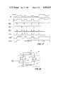
- FIG. 17is a timing diagram for signals associated with the circuit of FIG. 16.
- FIG. 18is a schematic diagram of an alternate embodiment of the tuned coil transponder circuit.
- FIG. 19is a block diagram of an implant communications module with a reed switch for receiving externally transmitted data.
- FIG. 20is a block diagram of a communication system in which the transponder doubles as a receiver for carrier modulated transmission.
- FIG. 21is a block diagram of a communications module for an implant with a battery charger energized by the output of the transponder.
- FIGS. 1 and 2illustrate the physical aspects of a preferred hand-held two-way telemetry head 10 according to the invention.
- Telemetry head 10includes an inverted cup-shaped upper shell 12 having an integral handle 12a with a pushbutton 14.
- the upper shell 12is preferably a single injection molded part of acrylonitrile-butadiene-styrene (ABS) thermoplastic.
- ABSacrylonitrile-butadiene-styrene
- the cup-shaped portion of the upper shell 12includes a grommeted rear opening 12b for a cable (FIG. 9) and an indicator light 16 mounted on the upper surface thereof.
- a circular lower shell or lens 18is designed to be snap-fit into the circular opening in the bottom of upper shell 12.
- the lens 18is made of an injection molded thermoplastic which is relatively transparent to infrared wavelengths of light.
- a rigid disc-shaped printed circuit board 20is suspended by a plurality of screws which engage downwardly projecting studs 12c, as shown in FIG. 2.
- the board 20carries the various electrical components associated with the telemetry circuitry of FIGS. 10 and 13-16.
- a combined triple coil and LED assembly 22is rigidly suspended from the printed circuit board 20 as shown in FIG. 2.
- the front face of the assembly 22abuts the inside surface of the lens 18.
- An optional coil 24(used to actuate reed switches for programming) surrounds the assembly 22 and is attached to the inside of the lens 18 for removal therewith.
- the coil and LED assembly 22includes a plastic spool 26 with three similar coaxial annular grooves 26a, 26b and 26c, about 1 millimeter (mm) wide and 25 mm in inner diameter in which electrical coils 28, 30 and 32, respectively, are wound.
- the groovesare axially spaced so that the outer coils 28 and 32 are each displaced about 1 centimeter (cm) from the center coil 30.
- the axial distance between the front coil 32 and the adjacent face of the spool 26should be as small as practical for example about 1 mm.
- a coaxial bore 26d in the spool 26receives an axially adjustable brass tuning slug 34.
- IR LED's 36are mounted in circumferentially equally spaced through holes 26f.
- the LED'smay be secured by introducing a small amount of silastic or other potting material into the through holes.
- the beam leads on each LED 36are plugged into an annular printed circuit board 38 arranged coaxially behind the flange 26e.
- Four more LED's 40are symmetrically mounted inside of the front coil 32 in corresponding through-holes.
- FIGS. 5 and 6illustrate an implantable physiological stimulator 50 or "implant”, such as a neural stimulator or cardiac pacer of the type manufactured by Cordis Corporation, the assignee of the present application.
- the enclosure for the implantis hermetically sealed to avoid contaminating the electronic components.
- the enclosuretypically comprises a relatively thin flat metal case 52, preferably a deep drawn container made of titanium, and a neck portion 54 of epoxy in which the electrical connectors for the stimulator leads are potted.
- a relatively large flat wound transponder coil 56(FIG. 7) is mounted inside the metal case 52 parallel to the flat surface which lies closer to the patient's skin.
- the spacing between the coil and the inside of the case and other metallic components in the implantis preferably maximized to reduce stray capacitance which lowers the Q of the tuned coil as discussed below.
- the other components of the transponderare also located within the metal case 52 along with the internal components of the stimulator.
- An infrared transparent window 60 preferably of sapphireis hermetically sealed in the center of the flat side of the titanium case 52 with the photodiode 58 located just beneath the window surrounded by the transponder coil 56, as shown in FIGS. 5 and 6.
- FIG. 8also illustrates in phantom an alternative ring configuration for the coil, designated coil 56'.
- a cylindrical coil with an axial thickness slightly less than the inside width of the case 52is mounted inside the outer ring of the case. It is of course possible that the future may see the development of adequately nonpermeable plastic potting materials to replace the presently preferred metal case. This would ease the location requirements on both the photodiode and the coil.
- FIG. 9illustrates the physiological stimulator 50 of FIGS. 5 and 6 implanted with electrical leads connected in a suitable portion of a human body 62.
- the physicianplaces the face of the telemetry head against the skin adjacent to the implant 50 for noninvasive two-way communication with the implant.
- a table-top programmer console(not shown) is connected by cable to the telemetry head.
- LED's 36 and 40in the bottom of the telemetry head 10 correspond to the 16 diodes illustrated in the LED driver circuit 66 of FIG. 10.
- the circuit 66is operated from the battery voltage supply, V BB , for the telemetry head 10.
- Transistors Q2 and Q3are N channel voltage operated metal oxide semiconductor (VMOS) field effect transistors (FET's) which drive the IR LED's D1-D16. IR LED's are preferred since they are more efficient at percutaneous transmission.
- a positive dc IR DRIVE signal(e.g., V BB -2V) the input to line 8, lights the diodes simultaneously in a predetermined pulse width modulation code for data transmission from the telemetry head 10 to the implant.
- FIG. 11shows the implanted communications module 70 having an IR receiver circuit 72 which includes the photodiode 58 (FIG. 6) for receiving optically transmitted data from the telemetry head 10.
- the decrease in resistance of the photodiode 58 when exposed to infrared lightlowers the voltage input to a linear amplifier 74 whose output resets a data flip-flop 76.
- the inverted output Q-bar of the flip-flop 76provides the data output to decoder circuitry (not shown) in the implant.
- the data outputis an exact replica of the data transmitted from the telemetry head.
- the pulse code for IR transmissionis binary pulse width modulation: a 1 millisecond (ms) pulse is a binary "0", a 2 ms pulse is a binary "1”, and the pulse-to-pulse period is 3 ms.
- a typical data wordmight comprise a string of 32 pulses.
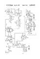
- FIG. 12provides an overview at the system level of the reflected signal telemetry system used for transmitting data from the implant.
- the external reflected signal telemetry unit 80 in the telemetry head 10includes a carrier transmitter 82 having an oscillator 84 which produces a continuous wave myriametric frequency electrical output at about 16 kHz.
- the oscillator outputis fed via a driver amplifier 86 to the middle coil 30 in the triple coil assembly 22.
- the reflected signal transponder 88includes the coil 56 (FIG. 7).
- the ends of the coil 56are connected in parallel with a capacitor 90 and a semiconductor switch 92 which forms the load into which the tuned coil (i.e., coil 56 with capacitor 90) is terminated electrically.
- the resonant or bandpass frequency of the tuned coilis centered at the carrier frequency, 16 kHz.
- the oscillating current through the coil 30 in the telemetry head 10establishes a magnetic field which radiates into the adjacent implant and induces a corresponding voltage in the tuned coil 56 which in turn reradiates a secondary magnetic field at the same carrier frequency.
- the semiconductor switch 92when conducting, is a low resistance shunt across the tuned coil which removes the capacitive reactance of the transponder and thus slightly increases the amplitude and alters the phase of the reflected signal.
- the control input to the switch 92is a digital data signal generated within the implant with the desired format of the pulse width modulation code (i.e., 1 ms and 2 ms switch closures with a pulse-to-pulse interval of 3 ms).
- a specific embodiment of the transponder 88is shown in FIG. 11, in which the switch 92 is a bipolar NPN transistor. This arrangement facilitates referencing the output voltage across the coil 56 to negative ground, which is used, for example, is neural stimulators manufactured by Cordis Corp. Referencing the voltage to ground, however, is not essential to operation of the reflected signal telemetry system.
- phase shift detector 98is connected to point A in the output to the oscillator coil 30 in order to receive the carrier signal as a reference input.
- the wiper of potentiometer R54picks off the differential voltage signal induced in the pickup coils 28 and 32 which forms input B to the phase shift detector 98.
- the phase shift detector 98produces an output level indicative of the displacement of the phase angle of the received signal B relative to the carrier signal A.
- the phase angle output level of the detector 98is passed to an acquisition circuit 100 which produces a logic output level indicative of acquisition when the output level of detector 98 exceeds a threshold value.
- the output of detector 98is fed to a signal processing circuit 102 which reconstructs the data input signal modulating the phase angle of the received signal B.
- FIGS. 10IR XMTR
- 13-16The schematic diagrams in FIGS. 10 (IR XMTR) and 13-16 define specific telemetry head circuitry utilizing both discrete components and integrated circuits which, except for the coils and LED's, are located on the printed circuit board 20 (FIG. 2) in the telemetry head 10.
- the circuitryoperates on three positive dc voltages V BB , V 1 and V 2 (plus ground).
- V 1 and V 2are derived from V BB by a voltage regulated power supply (not shown) in the telemetry head 10.
- Major input and output linesare indicated by upright triangles. These lines, along with V BB and ground, are connected by multiconductor cable to the aforementioned programmer console which produces the various enable signals and processes the acquisition and data outputs of the telemetry head 10.
- a table of exemplary values and designations of the componentsfollows the discussion of FIG. 17.
- FIG. 13illustrates the carrier oscillator 84 followed by power amplifier 86, an integrated circuit U1, which drives the oscillator coil 30.
- the oscillator 84is implemented by a phase shift oscillator with an output frequency tuned by resistor R4 to 16 kHz.
- Potentiometer R7adjusts the output level of amplifier U1.
- the capacitor C9 and coil 30form a series resonant circuit also tuned to 16 kHz.
- a high frequency suppression networkis provided by resistor R51 and capacitor C27.
- Muting of the transmitter 82is accomplished by pulling DRIVE ENABLE line number 3 low. When DRIVE ENABLE is high, the transmitter is on. Diode CR5 provides noise immunity at amplifier U1 since pin 6 of U1 is an analog input with a gain of 50.
- the front coil 32is the primary reflected signal receiving coil.
- the back coil 28is used to balance out the transmitted signal. This balancing is accomplished by manipulating the potentiometer R54 and the slug 34 in the coil assembly 22 (FIG. 4). Complete nulling of transmitted signal reception is probably neither feasible nor desirable.
- the phase shift detector 98shown in FIG. 14, is a zero crossing phase comparator.
- An integratorproduces a dc voltage proportional to the difference in phase between the transmitted signal A and the received signal B.
- Signal Ais attenuated by resistive network R9 and R11 and squared up by a Schmidt trigger U2A.
- a letter following an integrated circuit designation such as U2specifies an identical integrated circuit or fraction of a multiple circuit.
- Signal B from the pickup coils(pot. R54, FIGS. 12, 13) is amplified and limited by operational amplifier U3A then squared up by U3B and U2B.
- Diodes CR1 and CR2limit the input swing into U3A, for example, to 1 volt peak-to-peak.
- the capacitor C30assures symmetrical limiting regardless of the offset voltage out of amplifier U3A.
- the squared up reference signal Asets the integrate latch U4 (first flip-flop in dual flip-flop U4) whose output Q1 (line I) turns on the analog integrator U7A.
- the squared up received signal Bresets the integrate latch which stops the integration.
- a transfer one-shot U5produces a pulse T for about 1 microsecond to operate the gates U6C and U6D.
- the voltage across integrating capacitor C15is then transferred through transmission gates U6C and U6D to the sample and hold amplifier U7B.
- the second flip-flop circuit in U4is set.
- the Q2 output of the second flip-flopretsets the integrator through the R output line to clear the integrator for the next cycle.
- Resistor R23(FIG. 14) following transmission gate U6A provides a pull down to the same potential as the noninverting input of the integrator U7A to insure that integration is completely stopped.
- Resistor R25, and the transmission gates U6C and U6Dform a low leakage sample and hold gate by feeding back the hold voltage from U7B to reduce the potential difference across U6D to near zero.
- the output of sample and hold circuit U7Bwhich forms the output of detector 98, is a dc voltage representing the phase shift or phase angle between the reference carrier signal A and the received signal B from the pickup coils 28 and 32.
- the systemis preferably calibrated so that the output of U7B is about 20 millivolts per degree phase shift at 16 kHz.
- An increase in the phase lagfor example by shunting the tuned coil in the transponder 88 (FIG. 12) normally results in a lower output level from the phase detector 98.
- FIG. 15illustrates an acquisition circuit 100 which senses the proximity of the telemetry head 10 to the implant 50 (FIGS. 9 and 12).
- the dc phase angle voltageis applied to the non-inverting input of a comparator U8A with an adjustable threshold.
- the comparator U8A thresholdis adjusted to 4 volts.
- the comparator outputU8A, pin 1
- the LED D17 glowsfor indicator light 16 of FIG. 1
- the acquisition output line 6goes high.
- the dc phase angle voltagecould be converted to an analog signal to drive a meter calibrated to indicate acquisition.
- each time the switch 92 closesan artifact is produced in the composite reflected signal from the implant, namely a discrete phase shift.
- the relative phase of the received signal Bhas been observed to change, for example, from 151 degrees to 195 degrees, when the tuned coil is shunted out. Both the amplitude change and the phase change of the actual reflected signal are believed to contribute to the phase shift appearing in signal B.
- the ac portion of the signal at the output of the phase shift detector 98thus represents phase modulation by the implanted transponder 88.
- phase modulationcould be analog, binary pulse width modulation is preferred as shown in the top line of FIG. 17 illustrating the phase angle voltage waveform from detector 98.
- a pulse (switch closure) of 1 ms durationis designated as a binary "0”
- a 2 ms durationrepresents a binary "1”
- the pulse-to-pulse repetition periodis 3 ms, long enough for about 48 cycles of the carrier frequency.
- This code formatis identical to that used for IR transmission into the implant.
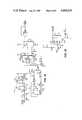
- FIG. 16illustrates the signal processing circuit 102 which performs the final demodulation and reproduces the transmitted data from the dc phase angle voltage.
- the linear amplifier U9When the linear amplifier U9 is enabled by the TELEMETRY ENABLE 1 (signal on line 4) going low, the dc phase angle voltage is boosted to logic levels.
- the amplified signaloperates the dual channel Schmidt trigger arrangement U10A-U10C to trigger the first one-shot in dual one-shot circuit U11. This combination of logic circuitry adds to the noise immunity of the system.
- the output of the first one-shot (mono No. 1) of U11is used to trigger both the output latch U12 and the second one-shot (mono No. 2) of U11.
- Mono No. 2is a missing pulse detector which resets the output latch after 5 ms of inactivity.
- the output of latch U12is buffered by voltage follower amplifier U88 whose output forms the data output of the telemetry lead 10 with positive logic TTL level pulse width modulated code.
- the purpose of the TELEMETRY ENABLE 1 signal (line 4) in FIG. 16is to hasten the settling time of the linear amplifier U9 after a transient caused for example by turning on the power amplifier (DRIVE ENABLE) or infrared or reed switch programming transmission from the telemetry head.
- the circuit comprised of transistor Q4, resistors R50 and R13 and diode CR6represents a time constant shortening circuit. Resistor R50 has much lower resistance than R30. Thus by pulling down line 4 (e.g. to 0 volts), Q4 is turned on and the normal time constant (C17 ⁇ R30) is reduced to (C17 ⁇ R50), 0.15 ms instead of 1.5 ms, for example.
- TELEMETRY ENABLE 2goes high (e.g., +6 volts) to enable mono No. 1 of U11 and low to blank unwanted data by holding mono No. 1 off whenever telemetry is not being received.
- the NAND gate U10D inputsare normally high.
- One channelis responsive to the rising edge of the transition in the phase angle voltage when the transponder is keyed, and the other channel is responsive to the falling edge.
- this dual channel systemprovides immunity to data inversion.
- the respective transitionis differentiated to briefly pulse the respective trigger input to the NAND gate low.
- the output of the NAND gate U10Dis a full string of upright pulses corresponding to transitions in the phase angle voltage. These pulses operate mono No. 1 (U11) which has a brief (e.g., 100 microsec.) on time. The rising edge of mono No.
- Mono No. 1toggles the output latch to reproduce the transmitted data.
- Mono No. 2is also triggered by the rising edge of mono No. 1 and resets the output latch after 5 ms of inactivity without being retriggered. This function prevents the output latch from being left in the high state indefinitely by noise, as illustrated in FIG. 17.
- the operational sequence for two-way communication between the telemetry head 10 and the implant 50involves three distinct phases: an acquisition mode, a transmission or programming mode in which data is sent to the implant, followed by a reflected signal telemetry mode in which data is sent from the implant to the telemetry head.
- an acquisition modea transmission or programming mode in which data is sent to the implant
- a reflected signal telemetry modein which data is sent from the implant to the telemetry head.
- There are two modalities for data transmission to the implantnamely, IR transmission and conventional magnetic pulse transmission. Both may use the same pulse width modulated code format.
- the implantis equipped with an IR receiver.
- the following sequence of actionsillustrates a typical two-way communication initiated by a physician who desires to program new stimulation pulse parameters for an implant.
- the physiciandecides on and selects the desired parameters at the programming console and then turns on the electrical power (V BB ) to the telemetry head.
- the telemetry carrier transmitter 82is activated by DRIVE ENABLE going high.
- the physicianpositions the telemetry head 10 over the implant 50 as shown in FIG. 9.
- the indicator light 16(diode D17) is turned on.
- inside the implantwith reference to FIG.
- the voltage induced in the passive transponder coil 56is applied by a transistor switch 104, which turns on at 0.6 volts, for example, to trigger one-shot 106 which activates the formerly dormant IR receiver circuit 72. If the implant has a reed switch data receiving circuit in lieu of an IR receiver, this activating step is unnecessary.
- the IR transmission modebegins when the physician presses the pushbutton 14 (FIG. 1) which applies V 1 to an output line connected to the programmer console. If magnetic pulse transmission were being used instead of IR transmission the DRIVE ENABLE signal would go low to turn off the carrier transmitter during magnetic pulse transmission to avoid interference. However, if IR transmission is used, the carrier transmitter may remain on. IR DRIVE signals are produced from the console in accordance with the preselected pulse parameters chosen by the physician. The string of IR pulses representing the first data word, for example, is transmitted and received and decoded in the implant.
- the reflected signal telemetry modeacquisition is first reverified by turning on the carrier transmitter 82 if it has been turned off in the meantime and relighting the indicator light 16 on the telemetry head.
- the TELEMETRY ENABLE 1 signalgoes high and 1 ms later the TELEMETRY ENABLE 2 signal goes high.
- Data transmitted by the transponder 88can now be received and processed by the telemetry lead 10.
- TELEMETRY ENABLE 2goes low and TELEMETRY ENABLE 1 goes low.
- IR transmissioncan be resumed.
- the implantcan answer back to confirm the programming data after each data word or string of programming pulses. After the last string of pulses has been sent and verified by telemetry the electrical power to the programming head is turned off which deactivates the acquisition indicator 16.
- FIG. 18illustrates an alternate embodiment of the resonant transponder 88 in which the switch 92 for shunting the tuned coil 56 and capacitor 90 is implemented by a pair of P channel VMOS FET's 110 and 112.
- Each of these transistorshas a built-in parasitic diode 110a, 112a from source to drain which lowers the on resistance during the inverted operation, that is to say, when the drain is more positive than the source.
- the diodes as well as the transistorsare connected in series opposition so that one of the diodes is always reverse-biased.
- the complementary symmetryremoves any tendency for the shunt circuit to exhibit different characteristics on the positive and negative half cycles of the signal across the tuned coil.
- FIG. 18is suitable for cardiac pacers and other stimulators which employ a reed switch 114, as shown in FIG. 19, in lieu of an IR receiver for receiving programming pulses.
- the transmission to the implant phaseis carred out by pulsing the large reed switch coil 24 (FIG. 2) in the telemetry head 10 according to a similar pulse width modulated code or a length-coded string of identical pulses, for example.
- the carrier transmitter 82 in the headis turned off to avoid adversely affecting the operation of the reed switch. Afterwards, the transmitter 82 is turned back on to enable reflected signal telemetry from the transponder 88 of FIG. 18.
- the reed switch coil 24 and IR transmitter 66 (FIG. 10) in the telemetry head 10represent alternative modes of data transmission into the implant.
- implants which have IR receiversmight include a reed switch which can be operated by the patient with a magnet for turning the implanted stimulator on or off in an emergency.
- the reed switch coil 24could, of course, be used for this purpose as well if desired.
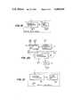
- FIG. 20shows an alternative means of data transmission into the implant.
- the carrier generated by the carrier transmitter 82 in the reflected signal telemetry unit 80 of the head 10is modulated by a carrier modulation circuit 116 which superimposes a data signal on the radiated magnetic carrier.
- the modulated carrieris picked up by the tuned coil in the transponder 88, acting as a secondary winding, and fed to a demodulator circuit 118 to recover the transmitted information signal.
- the transponder 88in this case doubles as a data receiver and data transmitter.
- IR transmissionis preferred because of its immunity to common electromagnetic interference.
- the tuned coil in the transponder 88is also used as the secondary in a transformer type battery charger 120 including suitable rectifier circuitry.
- batteriese.g., nickel cadmium
- a variety of modulation systems and carrier frequenciescan be used in accordance with the invention. Selection of the myriametric frequency range (3 kHz to 30 kHz) coincides with the low pass 30 kHz cutoff characteristic of titanium and stainless steel leak proof implant cases. The optimum frequency selection depends on several factors. First, the Q of the implanted tuned coil is impaired by the capacitance created by the nearby case and other metallic components. The Q tends also to further decrease with increasing frequency. Thus 25 kHz, while within the low pass window, results in greater losses. Below 10 kHz the number of cycles per 3 ms pulse-to-pulse interval is low enough to introduce decoding errors. Moreover, it takes more energy at lower frequencies to induce the same voltage.
- the upper audio band(optimally 16 kHz) represents a happy medium between these extremes. This is somewhat surprising because it is well within the audio frequency band for loud speakers, for example, and because of the ubiquitous neighboring 15 kHz noise of the sync signal television frequencies. However, these noise factors do not present an interference problem since the sync signal is mostly electrostatic instead of magnetic and both audio and sync signals are rejected by the phase demodulation circuitry. Thus any frequency in the vicinity of 16 kHz is ideal. In other environments, however, with other modulation schemes, a different frequency may prove to be optimum for the telemetry system of the invention.
- the controlled impedance across the transponder 88may be a continuously variable resistance for example varying in accordance with an analog input signal.
- Digital codeis preferred for medical applications because of its noise rejection capability and compatibility with the type of data to be transmitted, namely, pulse parameter selection codes.
- the telemetry systems disclosed hereincan be used separately or in various combinations. Two different modes can be used simultaneously, if desired, to transmit identical code for greater noise immunity. These systems may also be suitable for other low energy, telemetry applications for isolated devices.
- the analog timing circuitry for the phase detector 98 and signal processing circuit 102can be implemented as desired by digital timing circuitry.
- the disclosed analog systemcan resolve one degree of phase at 16 kHz, and a one degree phase interval represents a scant 174 nanoseconds. To count at twice that rate would require clock frequencies in excess of 10 megahertz.
- Reflected signal telemetryuses the lowest possible current drain because practically all of the power comes from outside of the implant.
- the compact physical dimensions of the resonant transponder disclosed hereinare compatible with space constraints within an implant.
- Phase modulationis detectable in a single cycle (or half cycle), has inherently low interference and accomodates digital pulse transmission techniques.
- the same pulse width modulation codecan be used for reflected signal telemetry from the implant and for IR or magnetic pulse transmission to the implant.
- IR transmissionprovides fast digital data with low interference, and when used in conjunction with the reflected signal telemetry system, the implanted transponder can turn on a dormant IR receiver to conserve power and to provide a dual mode access code for data reception.
- the transponder coilthus has numerous functions including telemetry, activation of the IR receiver, and enhancement of the acquisition mode and is further adaptable for modulated carrier reception and battery charging functions.
- the triple coil assemblyis compatible with a compact array of IR LED's which forms a relatively low cost, light weight compact two-way telemetry head.
Landscapes
- Health & Medical Sciences (AREA)
- Life Sciences & Earth Sciences (AREA)
- Engineering & Computer Science (AREA)
- Physics & Mathematics (AREA)
- Animal Behavior & Ethology (AREA)
- Veterinary Medicine (AREA)
- Public Health (AREA)
- Biomedical Technology (AREA)
- General Health & Medical Sciences (AREA)
- Biophysics (AREA)
- Molecular Biology (AREA)
- Surgery (AREA)
- Medical Informatics (AREA)
- Heart & Thoracic Surgery (AREA)
- Pathology (AREA)
- Computer Networks & Wireless Communication (AREA)
- Electromagnetism (AREA)
- Acoustics & Sound (AREA)
- Nuclear Medicine, Radiotherapy & Molecular Imaging (AREA)
- Radiology & Medical Imaging (AREA)
- Electrotherapy Devices (AREA)
Abstract
Description
TABLE ______________________________________ R1 10 kilohms C3 560 picofarads R2 68 " C4 " " R3 8.2 " C5 " " R4 20 " C7 630 picofarads R5 10 " C8 0.68 microfarad R6 3.3 " C9 0.22 " R7 5 " C10 0.01 " R8 1 kilohm C11 560 picofarads R9 10 kilohms C12 0.001 microfarad R11 6.8 " C13 0.01 " R12 2 " C14 100 picofarads R13 10 " C15 0.001 microfarad R14 5.1 " C16 0.002 " R15 5.1 " C17 1.5 microfarads R16 1 megohm C18 120 picofarads R17 1 kilohm C19 0.01 microfarad R18 1 " C20 0.01 " R19 100 kilohms C21 220 picofarads R20 1 kilohm C22 " " R21 10 kilohms C23 150 " R22 51 " C24 0.01 microfarad R23 1 kilohm C26 100 microfarads R24 1 " C27 0.1 microfarad R25 100 kilohms C28 50 picofarads R26 15 " C29 0.1 microfarad R27 1 kilohm C30 0.01 " R28 1 megohm C32 680 picofarads R29 1 kilohm Q1 2N930 R30 1 kilohm U1 LM380 R31 1 " U2 CD40106BE R32 300 kilohms U3 CD3240DE R33 100 " U4 CD4013BE R34 2 " U5 CD4098BE R35 100 " U6 CD4016BE R36 2 " U7 CA3240AE R37 100 " U8 CA3240AE R38 51 " U9 CA3130S R39 5 " U10 CD4093BE R40 620 " U11 CD4098BE R41 1 megohm U12 CD4013BE R42 51 kilohms one-shot 106 CD4098 R43 1 kilohm flip-flop 76 CD4013 R44 10 kilohms amplifier 74 LM3078 R45 1 kilohm R46 1 " R47 10 ohms R48 10 " R49 120 " R50 100 " R51 2.7 ohms R52 2 kilohms R53 2 " R54 20 " R55 2 " R56 2 " R57 10 " R58 15 " R59 68 " R60 43 " R61 50 " R62 10 " D1-D16 920 nanometer wavelength, 0.4 amp.Coil 30 300 turns (25 mm dia.) No. 34 gauge enameled copper wire Coils 28, 32 100 turns (25 mm dia.) No. 40 gauge enameledcopper wire Coil 56 100 flat wound turns of No. 34 gauge enameled copper wire with 4 cm outer diameter and 2 cminner diameter Coil 24 84 turns of 14 gauge enameled copper wire driven at 20 amps. V.sub.BB +17.5 volts V.sub.1 +6 volts V.sub.2 +12 volts ______________________________________
Claims (21)
Priority Applications (1)
| Application Number | Priority Date | Filing Date | Title |
|---|---|---|---|
| US06/406,367US4494545A (en) | 1980-05-27 | 1982-08-09 | Implant telemetry system |
Applications Claiming Priority (2)
| Application Number | Priority Date | Filing Date | Title |
|---|---|---|---|
| US06/153,093US4361153A (en) | 1980-05-27 | 1980-05-27 | Implant telemetry system |
| US06/406,367US4494545A (en) | 1980-05-27 | 1982-08-09 | Implant telemetry system |
Related Parent Applications (1)
| Application Number | Title | Priority Date | Filing Date |
|---|---|---|---|
| US06/153,093DivisionUS4361153A (en) | 1980-05-27 | 1980-05-27 | Implant telemetry system |
Publications (1)
| Publication Number | Publication Date |
|---|---|
| US4494545Atrue US4494545A (en) | 1985-01-22 |
Family
ID=26850164
Family Applications (1)
| Application Number | Title | Priority Date | Filing Date |
|---|---|---|---|
| US06/406,367Expired - LifetimeUS4494545A (en) | 1980-05-27 | 1982-08-09 | Implant telemetry system |
Country Status (1)
| Country | Link |
|---|---|
| US (1) | US4494545A (en) |
Cited By (91)
| Publication number | Priority date | Publication date | Assignee | Title |
|---|---|---|---|---|
| US4541431A (en)* | 1984-09-20 | 1985-09-17 | Telectronics Pty. Ltd. | Use of telemetry coil to replace magnetically activated reed switch in implantable devices |
| US4681111A (en)* | 1985-04-05 | 1987-07-21 | Siemens-Pacesetter, Inc. | Analog and digital telemetry system for an implantable device |
| US4847617A (en)* | 1987-08-14 | 1989-07-11 | Siemens-Pacesetter, Inc. | High speed digital telemetry system for implantable devices |
| US4871351A (en)* | 1984-09-28 | 1989-10-03 | Vladimir Feingold | Implantable medication infusion system |
| US4941201A (en)* | 1985-01-13 | 1990-07-10 | Abbott Laboratories | Electronic data storage and retrieval apparatus and method |
| US5058581A (en)* | 1990-02-20 | 1991-10-22 | Siemens-Pacesetter, Inc. | Telemetry apparatus and method for implantable tissue stimulator |
| US5168871A (en)* | 1990-11-09 | 1992-12-08 | Medtronic, Inc. | Method and apparatus for processing quasi-transient telemetry signals in noisy environments |
| US5193540A (en)* | 1991-12-18 | 1993-03-16 | Alfred E. Mann Foundation For Scientific Research | Structure and method of manufacture of an implantable microstimulator |
| US5193539A (en)* | 1991-12-18 | 1993-03-16 | Alfred E. Mann Foundation For Scientific Research | Implantable microstimulator |
| US5214409A (en)* | 1991-12-03 | 1993-05-25 | Avid Corporation | Multi-memory electronic identification tag |
| US5235326A (en)* | 1991-08-15 | 1993-08-10 | Avid Corporation | Multi-mode identification system |
| US5257011A (en)* | 1991-12-03 | 1993-10-26 | Avid Corporation | Data altering means for multi-memory electronic identification tag |
| US5342408A (en)* | 1993-01-07 | 1994-08-30 | Incontrol, Inc. | Telemetry system for an implantable cardiac device |
| US5423334A (en)* | 1993-02-01 | 1995-06-13 | C. R. Bard, Inc. | Implantable medical device characterization system |
| US5464017A (en)* | 1994-06-29 | 1995-11-07 | Juang; Jing-Song | LED display blood pressure meter |
| US5626630A (en)* | 1994-10-13 | 1997-05-06 | Ael Industries, Inc. | Medical telemetry system using an implanted passive transponder |
| US5630835A (en)* | 1995-07-24 | 1997-05-20 | Cardiac Control Systems, Inc. | Method and apparatus for the suppression of far-field interference signals for implantable device data transmission systems |
| EP0811396A1 (en)* | 1996-06-04 | 1997-12-10 | ELA MEDICAL (Société anonyme) | Device for filtering the signals of a medical apparatus signal, in particular of an active implanted medical apparatus |
| US5741315A (en)* | 1996-03-22 | 1998-04-21 | Ela Medical S.A. | Apparatus for receiving telemetry signals from active implantable medical devices |
| US5833714A (en)* | 1996-01-18 | 1998-11-10 | Loeb; Gerald E. | Cochlear electrode array employing tantalum metal |
| US5957958A (en)* | 1997-01-15 | 1999-09-28 | Advanced Bionics Corporation | Implantable electrode arrays |
| WO2001005467A1 (en)* | 1999-07-19 | 2001-01-25 | Medtronic, Inc. | A medical system having improved telemetry |
| US6223083B1 (en) | 1999-04-16 | 2001-04-24 | Medtronic, Inc. | Receiver employing digital filtering for use with an implantable medical device |
| US6295473B1 (en) | 1999-04-16 | 2001-09-25 | Medtronic, Inc. | Digital delay line receiver for use with an implantable medical device |
| FR2807948A1 (en)* | 2000-04-24 | 2001-10-26 | Medtronic Inc | Method for preventing stray alternating current magnetic fields from interfering with implantable medical devices, comprises switch connected in parallel with transmitting and receiving coil |
| US6400974B1 (en)* | 2000-06-29 | 2002-06-04 | Sensors For Medicine And Science, Inc. | Implanted sensor processing system and method for processing implanted sensor output |
| US6402689B1 (en) | 1998-09-30 | 2002-06-11 | Sicel Technologies, Inc. | Methods, systems, and associated implantable devices for dynamic monitoring of physiological and biological properties of tumors |
| US6418346B1 (en) | 1999-12-14 | 2002-07-09 | Medtronic, Inc. | Apparatus and method for remote therapy and diagnosis in medical devices via interface systems |
| US20020102212A1 (en)* | 2000-11-09 | 2002-08-01 | Black Robert D. | Methods, circuits and compositions of matter for in vivo detection of biomolecule concentrations using fluorescent tags |
| US6458157B1 (en)* | 1997-08-04 | 2002-10-01 | Suaning Gregg Joergen | Retinal stimulator |
| US20020147388A1 (en)* | 2001-04-06 | 2002-10-10 | Mass William R. | Passive telemetry system for implantable medical device |
| US6472975B1 (en) | 1994-06-20 | 2002-10-29 | Avid Marketing, Inc. | Electronic identification system with improved sensitivity |
| US20020193845A1 (en)* | 1999-03-24 | 2002-12-19 | Second Sight, Llc. | Optical Communications System for an Implantable Device |
| US20030125616A1 (en)* | 2001-11-30 | 2003-07-03 | Black Robert D. | Disposable single-use external dosimeters for use in radiation therapies |
| US6591139B2 (en)* | 2000-09-06 | 2003-07-08 | Advanced Bionics Corporation | Low-power, high-modulation-index amplifier for use in battery-powered device |
| US20030181794A1 (en)* | 2002-01-29 | 2003-09-25 | Rini Christopher J. | Implantable sensor housing, sensor unit and methods for forming and using the same |
| US6731976B2 (en) | 1997-09-03 | 2004-05-04 | Medtronic, Inc. | Device and method to measure and communicate body parameters |
| US20040197267A1 (en)* | 2003-02-19 | 2004-10-07 | Black Robert D. | In vivo fluorescence sensors, systems, and related methods operating in conjunction with fluorescent analytes |
| US20040204744A1 (en)* | 2003-04-14 | 2004-10-14 | Remon Medicaltechnologies Ltd. | Apparatus and methods using acoustic telemetry for intrabody communications |
| US20040230487A1 (en)* | 2003-05-13 | 2004-11-18 | Tripp Jeffrey William | Local data access system |
| US20040267233A1 (en)* | 2003-06-30 | 2004-12-30 | Codman Neuro Sciences Sarl | System and method for controlling an implantable medical device subject to magnetic field or radio frequency exposure |
| US20050003839A1 (en)* | 2003-05-13 | 2005-01-06 | Tripp Jeffrey William | Decision influence data system |
| US6895281B1 (en) | 2000-03-31 | 2005-05-17 | Cardiac Pacemakers, Inc. | Inductive coil apparatus for bio-medical telemetry |
| US20050287065A1 (en)* | 2001-04-23 | 2005-12-29 | Sicel Technologies, Inc. | Systems, methods and devices for in vivo monitoring of a localized response via a radiolabeled analyte in a subject |
| US20060016452A1 (en)* | 2004-07-20 | 2006-01-26 | Medtronic, Inc. | Locating an implanted object based on external antenna loading |
| US20060224129A1 (en)* | 1998-12-07 | 2006-10-05 | Beasley Jim C | Septum including at least one identifiable feature, access ports including same, and related methods |
| US20060247584A1 (en)* | 2005-03-04 | 2006-11-02 | C.R. Bard, Inc. | Access port identification systems and methods |
| US20060264898A1 (en)* | 2005-04-27 | 2006-11-23 | Beasley Jim C | Infusion apparatuses and related methods |
| US20070161884A1 (en)* | 2003-04-02 | 2007-07-12 | Sicel Technologies, Inc. | Methods, systems, and computer program products for providing dynamic data of positional localization of target implants |
| US20070219599A1 (en)* | 2006-03-15 | 2007-09-20 | Cherik Bulkes | Composite Waveform Based Method and Apparatus for Animal Tissue Stimulation |
| US20070233017A1 (en)* | 2006-10-18 | 2007-10-04 | Medical Components, Inc. | Venous access port assembly with radiopaque indicia |
| US20080039904A1 (en)* | 2006-08-08 | 2008-02-14 | Cherik Bulkes | Intravascular implant system |
| US20080082143A1 (en)* | 2006-09-29 | 2008-04-03 | Rongqing Dai | External coil assembly for implantable medical prostheses |
| US20080108949A1 (en)* | 2006-11-08 | 2008-05-08 | C. R. Bard, Inc. | Resource information key for an insertable medical device |
| US20080208516A1 (en)* | 2004-11-04 | 2008-08-28 | Smith & Nephew, Inc. | Cycle and Load Measurement Device |
| US20080275531A1 (en)* | 2007-05-04 | 2008-11-06 | Cherik Bulkes | Implantable high efficiency digital stimulation device |
| US20080300597A1 (en)* | 2005-08-23 | 2008-12-04 | Smith & Nephew, Inc. | Telemetric Orthopaedic Implant |
| US20080319399A1 (en)* | 2007-06-20 | 2008-12-25 | Medical Components, Inc. | Venous access port with molded and/or radiopaque indicia |
| US20090024024A1 (en)* | 2007-07-19 | 2009-01-22 | Innovative Medical Devices, Llc | Venous Access Port Assembly with X-Ray Discernable Indicia |
| AU2006202503B2 (en)* | 1999-03-24 | 2009-04-23 | Second Sight Medical Products, Inc. | Retinal color prosthesis for color sight restoration |
| US20090156928A1 (en)* | 2007-11-07 | 2009-06-18 | C. R. Bard, Inc. | Radiopaque and septum-based indicators for a multi-lumen implantable port |
| US7553280B2 (en)* | 2000-06-29 | 2009-06-30 | Sensors For Medicine And Science, Inc. | Implanted sensor processing system and method |
| US20090204072A1 (en)* | 2005-03-04 | 2009-08-13 | C. R. Bard, Inc. | Access port identification systems and methods |
| US20100069743A1 (en)* | 2005-03-04 | 2010-03-18 | C. R. Bard, Inc. | Systems and methods for identifying an access port |
| US20100121283A1 (en)* | 2008-11-13 | 2010-05-13 | C. R. Bard, Inc. | Implantable medical devices including septum-based indicators |
| US20100152621A1 (en)* | 2007-02-23 | 2010-06-17 | Smith & Nephew, Inc. | Processing sensed accelerometer data for determination of bone healing |
| US20100268165A1 (en)* | 2005-03-04 | 2010-10-21 | C. R. Bard, Inc. | Systems and methods for radiographically identifying an access port |
| US20110009828A1 (en)* | 2009-07-07 | 2011-01-13 | C.R.Bard, Inc. | Extensible internal bolster for a medical device |
| US20110118677A1 (en)* | 2009-11-17 | 2011-05-19 | C. R. Bard, Inc. | Overmolded access port including anchoring and identification features |
| US20110205083A1 (en)* | 2007-09-06 | 2011-08-25 | Smith & Nephew, Inc. | System and method for communicating with a telemetric implant |
| US8021324B2 (en) | 2007-07-19 | 2011-09-20 | Medical Components, Inc. | Venous access port assembly with X-ray discernable indicia |
| USD676955S1 (en) | 2010-12-30 | 2013-02-26 | C. R. Bard, Inc. | Implantable access port |
| USD682416S1 (en) | 2010-12-30 | 2013-05-14 | C. R. Bard, Inc. | Implantable access port |
| US8641676B2 (en) | 2005-04-27 | 2014-02-04 | C. R. Bard, Inc. | Infusion apparatuses and methods of use |
| US8704124B2 (en) | 2009-01-29 | 2014-04-22 | Smith & Nephew, Inc. | Low temperature encapsulate welding |
| US9265912B2 (en) | 2006-11-08 | 2016-02-23 | C. R. Bard, Inc. | Indicia informative of characteristics of insertable medical devices |
| US9474888B2 (en) | 2005-03-04 | 2016-10-25 | C. R. Bard, Inc. | Implantable access port including a sandwiched radiopaque insert |
| US9494081B2 (en) | 2013-05-09 | 2016-11-15 | Siemens Aktiengesellschaft | Turbine engine shutdown temperature control system with an elongated ejector |
| WO2017031311A1 (en)* | 2015-08-18 | 2017-02-23 | University Of Louisville Research Foundation, Inc. | Sync pulse detector |
| US9730764B2 (en) | 2015-10-02 | 2017-08-15 | Elucent Medical, Inc. | Signal tag detection components, devices, and systems |
| US9855376B2 (en) | 2014-07-25 | 2018-01-02 | Minnetronix, Inc. | Power scaling |
| US9987097B2 (en) | 2015-10-02 | 2018-06-05 | Elucent Medical, Inc. | Signal tag detection components, devices, and systems |
| US10149933B2 (en) | 2014-07-25 | 2018-12-11 | Minnetronix, Inc. | Coil parameters and control |
| US10154799B2 (en) | 2016-08-12 | 2018-12-18 | Elucent Medical, Inc. | Surgical device guidance and monitoring devices, systems, and methods |
| US10193395B2 (en) | 2015-04-14 | 2019-01-29 | Minnetronix, Inc. | Repeater resonator |
| US10278779B1 (en) | 2018-06-05 | 2019-05-07 | Elucent Medical, Inc. | Exciter assemblies |
| US10307581B2 (en) | 2005-04-27 | 2019-06-04 | C. R. Bard, Inc. | Reinforced septum for an implantable medical device |
| US10342908B2 (en) | 2015-01-14 | 2019-07-09 | Minnetronix, Inc. | Distributed transformer |
| US10406267B2 (en) | 2015-01-16 | 2019-09-10 | Minnetronix, Inc. | Data communication in a transcutaneous energy transfer system |
| US11344382B2 (en) | 2014-01-24 | 2022-05-31 | Elucent Medical, Inc. | Systems and methods comprising localization agents |
| US11890443B2 (en) | 2008-11-13 | 2024-02-06 | C. R. Bard, Inc. | Implantable medical devices including septum-based indicators |
Citations (4)
| Publication number | Priority date | Publication date | Assignee | Title |
|---|---|---|---|---|
| US3371272A (en)* | 1964-09-09 | 1968-02-27 | Stanton Joshua Clarke | Electromagnetic sensing probe structure and system for gaging proximity of metals and the like utilizing a linear variable differential transformer |
| US4063551A (en)* | 1976-04-06 | 1977-12-20 | Unisen, Inc. | Blood pulse sensor and readout |
| US4163447A (en)* | 1977-02-11 | 1979-08-07 | Thomas Orr | Heartbeat rate monitor |
| US4270545A (en)* | 1976-04-20 | 1981-06-02 | Rodler Ing Hans | Apparatus for examining biological bodies with electromagnetic fields |
- 1982
- 1982-08-09USUS06/406,367patent/US4494545A/ennot_activeExpired - Lifetime
Patent Citations (4)
| Publication number | Priority date | Publication date | Assignee | Title |
|---|---|---|---|---|
| US3371272A (en)* | 1964-09-09 | 1968-02-27 | Stanton Joshua Clarke | Electromagnetic sensing probe structure and system for gaging proximity of metals and the like utilizing a linear variable differential transformer |
| US4063551A (en)* | 1976-04-06 | 1977-12-20 | Unisen, Inc. | Blood pulse sensor and readout |
| US4270545A (en)* | 1976-04-20 | 1981-06-02 | Rodler Ing Hans | Apparatus for examining biological bodies with electromagnetic fields |
| US4163447A (en)* | 1977-02-11 | 1979-08-07 | Thomas Orr | Heartbeat rate monitor |
Cited By (236)
| Publication number | Priority date | Publication date | Assignee | Title |
|---|---|---|---|---|
| US4541431A (en)* | 1984-09-20 | 1985-09-17 | Telectronics Pty. Ltd. | Use of telemetry coil to replace magnetically activated reed switch in implantable devices |
| US4871351A (en)* | 1984-09-28 | 1989-10-03 | Vladimir Feingold | Implantable medication infusion system |
| US4941201A (en)* | 1985-01-13 | 1990-07-10 | Abbott Laboratories | Electronic data storage and retrieval apparatus and method |
| US4681111A (en)* | 1985-04-05 | 1987-07-21 | Siemens-Pacesetter, Inc. | Analog and digital telemetry system for an implantable device |
| US4847617A (en)* | 1987-08-14 | 1989-07-11 | Siemens-Pacesetter, Inc. | High speed digital telemetry system for implantable devices |
| US5058581A (en)* | 1990-02-20 | 1991-10-22 | Siemens-Pacesetter, Inc. | Telemetry apparatus and method for implantable tissue stimulator |
| US5168871A (en)* | 1990-11-09 | 1992-12-08 | Medtronic, Inc. | Method and apparatus for processing quasi-transient telemetry signals in noisy environments |
| US5235326A (en)* | 1991-08-15 | 1993-08-10 | Avid Corporation | Multi-mode identification system |
| US5257011A (en)* | 1991-12-03 | 1993-10-26 | Avid Corporation | Data altering means for multi-memory electronic identification tag |
| US5214409A (en)* | 1991-12-03 | 1993-05-25 | Avid Corporation | Multi-memory electronic identification tag |
| US5324316A (en)* | 1991-12-18 | 1994-06-28 | Alfred E. Mann Foundation For Scientific Research | Implantable microstimulator |
| US5193540A (en)* | 1991-12-18 | 1993-03-16 | Alfred E. Mann Foundation For Scientific Research | Structure and method of manufacture of an implantable microstimulator |
| US5193539A (en)* | 1991-12-18 | 1993-03-16 | Alfred E. Mann Foundation For Scientific Research | Implantable microstimulator |
| US5342408A (en)* | 1993-01-07 | 1994-08-30 | Incontrol, Inc. | Telemetry system for an implantable cardiac device |
| US5423334A (en)* | 1993-02-01 | 1995-06-13 | C. R. Bard, Inc. | Implantable medical device characterization system |
| US6472975B1 (en) | 1994-06-20 | 2002-10-29 | Avid Marketing, Inc. | Electronic identification system with improved sensitivity |
| US5464017A (en)* | 1994-06-29 | 1995-11-07 | Juang; Jing-Song | LED display blood pressure meter |
| US5626630A (en)* | 1994-10-13 | 1997-05-06 | Ael Industries, Inc. | Medical telemetry system using an implanted passive transponder |
| US5630835A (en)* | 1995-07-24 | 1997-05-20 | Cardiac Control Systems, Inc. | Method and apparatus for the suppression of far-field interference signals for implantable device data transmission systems |
| US5833714A (en)* | 1996-01-18 | 1998-11-10 | Loeb; Gerald E. | Cochlear electrode array employing tantalum metal |
| US5741315A (en)* | 1996-03-22 | 1998-04-21 | Ela Medical S.A. | Apparatus for receiving telemetry signals from active implantable medical devices |
| EP0811396A1 (en)* | 1996-06-04 | 1997-12-10 | ELA MEDICAL (Société anonyme) | Device for filtering the signals of a medical apparatus signal, in particular of an active implanted medical apparatus |
| US5957958A (en)* | 1997-01-15 | 1999-09-28 | Advanced Bionics Corporation | Implantable electrode arrays |
| US6458157B1 (en)* | 1997-08-04 | 2002-10-01 | Suaning Gregg Joergen | Retinal stimulator |
| US6731976B2 (en) | 1997-09-03 | 2004-05-04 | Medtronic, Inc. | Device and method to measure and communicate body parameters |
| US7769431B2 (en) | 1998-09-30 | 2010-08-03 | North Carolina State University | Methods, systems, and associated implantable devices for detecting radiation in patients undergoing treatment for cancer |
| US9662049B2 (en) | 1998-09-30 | 2017-05-30 | North Carolina State University | Methods and systems for monitoring patients undergoing treatment for cancer |
| US6402689B1 (en) | 1998-09-30 | 2002-06-11 | Sicel Technologies, Inc. | Methods, systems, and associated implantable devices for dynamic monitoring of physiological and biological properties of tumors |
| US6963770B2 (en) | 1998-09-30 | 2005-11-08 | North Carolina State University | Methods, systems, and associated implantable devices for dynamic monitoring of physiological and biological properties of tumors |
| US7778692B2 (en) | 1998-09-30 | 2010-08-17 | North Carolina State University | Methods, systems, and associated implantable devices for detecting radiation in patients undergoing treatment for cancer |
| US7756568B2 (en) | 1998-09-30 | 2010-07-13 | North Carolina State University | Methods, systems, and associated implantable devices for dynamic monitoring of physiological and biological properties of tumors |
| US7787937B2 (en) | 1998-09-30 | 2010-08-31 | North Carolina State University | Methods, systems, and associated implantable devices for detecting radiation in patients undergoing treatment for cancer |
| US20050228247A1 (en)* | 1998-09-30 | 2005-10-13 | Sicel Technologies, Inc. | Methods, systems, and associated implantable devices for dynamic monitoring of physiological and biological properties of tumors |
| US20050251033A1 (en)* | 1998-09-30 | 2005-11-10 | Sicel Technologies, Inc. | Methods, systems, and associated implantable devices for detecting radiation in patients undergoing treatment for cancer |
| US20100268078A1 (en)* | 1998-09-30 | 2010-10-21 | Scarantino Charles W | Methods and systems for monitoring patients undergoing treatment for cancer |
| US7010340B2 (en) | 1998-09-30 | 2006-03-07 | North Carolina State University | Methods, systems, and associated implantable devices for dynamic monitoring of physiological and biological properties of tumors |
| US20060241407A1 (en)* | 1998-09-30 | 2006-10-26 | Sicel Technologies, Inc. | Methods, systems, and associated implantable devices for detecting radiation in patients undergoing treatment for cancer |
| US6963771B2 (en) | 1998-09-30 | 2005-11-08 | North Carolina State University | Methods, systems, and associated implantable devices for radiation dose verification for therapies used to treat tumors |
| US20030195396A1 (en)* | 1998-09-30 | 2003-10-16 | Scarantino Charles W. | Methods, systems, and associated implantable devices for dynamic monitoring of physiological and biological properties of tumors |
| US20040230115A1 (en)* | 1998-09-30 | 2004-11-18 | Scarantino Charles W. | Methods, systems, and associated implantable devices for radiation dose verification for therapies used to treat tumors |
| US8380290B2 (en) | 1998-09-30 | 2013-02-19 | North Carolina State University | Implantable devices for dynamic monitoring of physiological and biological properties of tumors |
| US7171252B1 (en) | 1998-09-30 | 2007-01-30 | Sicel Technologies, Inc. | Methods, computer program products, and devices for calibrating chronically tissue implanted sensors using chronically tissue |
| US8608713B2 (en) | 1998-12-07 | 2013-12-17 | C. R. Bard, Inc. | Septum feature for identification of an access port |
| US8177762B2 (en) | 1998-12-07 | 2012-05-15 | C. R. Bard, Inc. | Septum including at least one identifiable feature, access ports including same, and related methods |
| US20060224129A1 (en)* | 1998-12-07 | 2006-10-05 | Beasley Jim C | Septum including at least one identifiable feature, access ports including same, and related methods |
| US7079900B2 (en)* | 1999-03-24 | 2006-07-18 | Second Sight Medical Products, Inc. | Electrode array for neural stimulation |
| AU2006202503B2 (en)* | 1999-03-24 | 2009-04-23 | Second Sight Medical Products, Inc. | Retinal color prosthesis for color sight restoration |
| US20020193845A1 (en)* | 1999-03-24 | 2002-12-19 | Second Sight, Llc. | Optical Communications System for an Implantable Device |
| US6223083B1 (en) | 1999-04-16 | 2001-04-24 | Medtronic, Inc. | Receiver employing digital filtering for use with an implantable medical device |
| US6295473B1 (en) | 1999-04-16 | 2001-09-25 | Medtronic, Inc. | Digital delay line receiver for use with an implantable medical device |
| WO2001005467A1 (en)* | 1999-07-19 | 2001-01-25 | Medtronic, Inc. | A medical system having improved telemetry |
| US6418346B1 (en) | 1999-12-14 | 2002-07-09 | Medtronic, Inc. | Apparatus and method for remote therapy and diagnosis in medical devices via interface systems |
| US6895281B1 (en) | 2000-03-31 | 2005-05-17 | Cardiac Pacemakers, Inc. | Inductive coil apparatus for bio-medical telemetry |
| FR2807948A1 (en)* | 2000-04-24 | 2001-10-26 | Medtronic Inc | Method for preventing stray alternating current magnetic fields from interfering with implantable medical devices, comprises switch connected in parallel with transmitting and receiving coil |
| US6510345B1 (en)* | 2000-04-24 | 2003-01-21 | Medtronic, Inc. | System and method of bridging a transreceiver coil of an implantable medical device during non-communication periods |
| US20090264718A1 (en)* | 2000-06-29 | 2009-10-22 | Sensors For Medicine And Science,Inc. | Implanted sensor processing system and method for processing implanted sensor output |
| US6400974B1 (en)* | 2000-06-29 | 2002-06-04 | Sensors For Medicine And Science, Inc. | Implanted sensor processing system and method for processing implanted sensor output |
| US7553280B2 (en)* | 2000-06-29 | 2009-06-30 | Sensors For Medicine And Science, Inc. | Implanted sensor processing system and method |
| US6591139B2 (en)* | 2000-09-06 | 2003-07-08 | Advanced Bionics Corporation | Low-power, high-modulation-index amplifier for use in battery-powered device |
| US20080228049A1 (en)* | 2000-11-09 | 2008-09-18 | Sicel Technologies, Inc. | Systems, Circuits and Apparatus For In Vivo Detection of Biomolecule Concentrations Using Fluorescent Tags |
| US20020102212A1 (en)* | 2000-11-09 | 2002-08-01 | Black Robert D. | Methods, circuits and compositions of matter for in vivo detection of biomolecule concentrations using fluorescent tags |
| US7378056B2 (en) | 2000-11-09 | 2008-05-27 | Sicel Technologies, Inc. | Circuits for in vivo detection of biomolecule concentrations using fluorescent tags |
| US20020147388A1 (en)* | 2001-04-06 | 2002-10-10 | Mass William R. | Passive telemetry system for implantable medical device |
| US6889086B2 (en)* | 2001-04-06 | 2005-05-03 | Cardiac Pacemakers, Inc. | Passive telemetry system for implantable medical device |
| US20050287065A1 (en)* | 2001-04-23 | 2005-12-29 | Sicel Technologies, Inc. | Systems, methods and devices for in vivo monitoring of a localized response via a radiolabeled analyte in a subject |
| US7011814B2 (en) | 2001-04-23 | 2006-03-14 | Sicel Technologies, Inc. | Systems, methods and devices for in vivo monitoring of a localized response via a radiolabeled analyte in a subject |
| US7966054B2 (en) | 2001-11-30 | 2011-06-21 | Sicel Technologies, Inc. | Disposable single-use external dosimeters for detecting radiation in fluoroscopy and other medical procedures/therapies |
| US7491942B2 (en) | 2001-11-30 | 2009-02-17 | Sicel Technologies, Inc. | Single-use internal dosimeters for detecting radiation in fluoroscopy and other medical procedures/therapies |
| US7557353B2 (en) | 2001-11-30 | 2009-07-07 | Sicel Technologies, Inc. | Single-use external dosimeters for use in radiation therapies |
| US20090250602A1 (en)* | 2001-11-30 | 2009-10-08 | Black Robert D | Single-use external dosimeters for use in radiation therapies |
| US20090127469A1 (en)* | 2001-11-30 | 2009-05-21 | Sicel Technologies, Inc. | Single-Use External Dosimeters for Use in Radiation Therapies and Related Devices and Computer Program Products |
| US8148696B2 (en) | 2001-11-30 | 2012-04-03 | SNC Holdings Corp. | Single-use external dosimeters for use in radiation therapies and related devices and computer program products |
| US20030125616A1 (en)* | 2001-11-30 | 2003-07-03 | Black Robert D. | Disposable single-use external dosimeters for use in radiation therapies |
| US7495224B2 (en) | 2001-11-30 | 2009-02-24 | Sicel Technologies, Inc. | Single-use external dosimeters for use in radiation therapies and related methods and systems |
| US20040236207A1 (en)* | 2001-11-30 | 2004-11-25 | Widener Steven R. | Single-use external dosimeters for use in radiation therapies and related methods, systems and computer program products |
| US7923694B2 (en) | 2001-11-30 | 2011-04-12 | Sicel Technologies, Inc. | Single-use external dosimeters for use in radiation therapies |
| US20110121188A1 (en)* | 2001-11-30 | 2011-05-26 | Black Robert D | Single-use internal dosimeters for detecting radiation in medical procedures/therapies |
| US20110210258A1 (en)* | 2001-11-30 | 2011-09-01 | Black Robert D | Disposable single-use external dosimeters for detecting radiation in fluoroscopy and other medical procedures/therapies |
| US20050010110A1 (en)* | 2001-11-30 | 2005-01-13 | Black Robert D. | Disposable single-use internal dosimeters for detecting radiation in medical procedures/therapies |
| US20050090738A1 (en)* | 2001-11-30 | 2005-04-28 | Black Robert D. | Disposable single-use external dosimeters for detecting radiation in fluoroscopy and other medical procedures/therapies |
| US7479108B2 (en) | 2002-01-29 | 2009-01-20 | Sicel Technologies, Inc. | Methods for using an implantable sensor unit |
| US20030181794A1 (en)* | 2002-01-29 | 2003-09-25 | Rini Christopher J. | Implantable sensor housing, sensor unit and methods for forming and using the same |
| US7510699B2 (en) | 2003-02-19 | 2009-03-31 | Sicel Technologies, Inc. | In vivo fluorescence sensors, systems, and related methods operating in conjunction with fluorescent analytes |
| US20040197267A1 (en)* | 2003-02-19 | 2004-10-07 | Black Robert D. | In vivo fluorescence sensors, systems, and related methods operating in conjunction with fluorescent analytes |
| US20070161884A1 (en)* | 2003-04-02 | 2007-07-12 | Sicel Technologies, Inc. | Methods, systems, and computer program products for providing dynamic data of positional localization of target implants |
| US20040204744A1 (en)* | 2003-04-14 | 2004-10-14 | Remon Medicaltechnologies Ltd. | Apparatus and methods using acoustic telemetry for intrabody communications |
| US20050003839A1 (en)* | 2003-05-13 | 2005-01-06 | Tripp Jeffrey William | Decision influence data system |
| US20040230487A1 (en)* | 2003-05-13 | 2004-11-18 | Tripp Jeffrey William | Local data access system |
| US7242981B2 (en) | 2003-06-30 | 2007-07-10 | Codman Neuro Sciences Sárl | System and method for controlling an implantable medical device subject to magnetic field or radio frequency exposure |
| US8090445B2 (en) | 2003-06-30 | 2012-01-03 | Codman Neuro Sciences Sárl | System and method for controlling an implantable medical device subject to magnetic field or radio frequency exposure |
| US20070239231A1 (en)* | 2003-06-30 | 2007-10-11 | Codman Neuro Sciences Sarl | System and method for controlling an implantable medical device subject to magnetic field or radio frequency exposure |
| US7672726B2 (en) | 2003-06-30 | 2010-03-02 | Codman Neuro Sciences Sárl | System and method for controlling an implantable medical device subject to magnetic field or radio frequency exposure |
| US20040267233A1 (en)* | 2003-06-30 | 2004-12-30 | Codman Neuro Sciences Sarl | System and method for controlling an implantable medical device subject to magnetic field or radio frequency exposure |
| US20100114060A1 (en)* | 2003-06-30 | 2010-05-06 | Codman Neuro Sciences Sarl | System and method for controlling an implantable medical device subject to magnetic field or radio frequency exposure |
| US20110118591A1 (en)* | 2004-07-20 | 2011-05-19 | Medtronic, Inc. | Locating an implanted object based on external antenna loading |
| US7878207B2 (en) | 2004-07-20 | 2011-02-01 | Medtronic, Inc. | Locating an implanted object based on external antenna loading |
| US8015978B2 (en) | 2004-07-20 | 2011-09-13 | Medtronic, Inc. | Locating an implanted object based on external antenna loading |
| US20060016452A1 (en)* | 2004-07-20 | 2006-01-26 | Medtronic, Inc. | Locating an implanted object based on external antenna loading |
| US20080208516A1 (en)* | 2004-11-04 | 2008-08-28 | Smith & Nephew, Inc. | Cycle and Load Measurement Device |
| US8388553B2 (en) | 2004-11-04 | 2013-03-05 | Smith & Nephew, Inc. | Cycle and load measurement device |
| US7959615B2 (en) | 2005-03-04 | 2011-06-14 | C. R. Bard, Inc. | Access port identification systems and methods |
| US8202259B2 (en) | 2005-03-04 | 2012-06-19 | C. R. Bard, Inc. | Systems and methods for identifying an access port |
| US11077291B2 (en) | 2005-03-04 | 2021-08-03 | Bard Peripheral Vascular, Inc. | Implantable access port including a sandwiched radiopaque insert |
| US20100069743A1 (en)* | 2005-03-04 | 2010-03-18 | C. R. Bard, Inc. | Systems and methods for identifying an access port |
| US20100211026A2 (en)* | 2005-03-04 | 2010-08-19 | C. R. Bard, Inc. | Access port identification systems and methods |
| US10905868B2 (en) | 2005-03-04 | 2021-02-02 | Bard Peripheral Vascular, Inc. | Systems and methods for radiographically identifying an access port |
| US7785302B2 (en)* | 2005-03-04 | 2010-08-31 | C. R. Bard, Inc. | Access port identification systems and methods |
| US20100268165A1 (en)* | 2005-03-04 | 2010-10-21 | C. R. Bard, Inc. | Systems and methods for radiographically identifying an access port |
| US10857340B2 (en) | 2005-03-04 | 2020-12-08 | Bard Peripheral Vascular, Inc. | Systems and methods for radiographically identifying an access port |
| US10675401B2 (en) | 2005-03-04 | 2020-06-09 | Bard Peripheral Vascular, Inc. | Access port identification systems and methods |
| US10265512B2 (en) | 2005-03-04 | 2019-04-23 | Bard Peripheral Vascular, Inc. | Implantable access port including a sandwiched radiopaque insert |
| US20090204072A1 (en)* | 2005-03-04 | 2009-08-13 | C. R. Bard, Inc. | Access port identification systems and methods |
| US10238850B2 (en) | 2005-03-04 | 2019-03-26 | Bard Peripheral Vascular, Inc. | Systems and methods for radiographically identifying an access port |
| US10179230B2 (en) | 2005-03-04 | 2019-01-15 | Bard Peripheral Vascular, Inc. | Systems and methods for radiographically identifying an access port |
| US9682186B2 (en) | 2005-03-04 | 2017-06-20 | C. R. Bard, Inc. | Access port identification systems and methods |
| US7947022B2 (en) | 2005-03-04 | 2011-05-24 | C. R. Bard, Inc. | Access port identification systems and methods |
| US20060247584A1 (en)* | 2005-03-04 | 2006-11-02 | C.R. Bard, Inc. | Access port identification systems and methods |
| US9603993B2 (en) | 2005-03-04 | 2017-03-28 | C. R. Bard, Inc. | Access port identification systems and methods |
| US9603992B2 (en) | 2005-03-04 | 2017-03-28 | C. R. Bard, Inc. | Access port identification systems and methods |
| US9474888B2 (en) | 2005-03-04 | 2016-10-25 | C. R. Bard, Inc. | Implantable access port including a sandwiched radiopaque insert |
| US8998860B2 (en) | 2005-03-04 | 2015-04-07 | C. R. Bard, Inc. | Systems and methods for identifying an access port |
| US8939947B2 (en) | 2005-03-04 | 2015-01-27 | C. R. Bard, Inc. | Systems and methods for radiographically identifying an access port |
| US20080140025A1 (en)* | 2005-03-04 | 2008-06-12 | C. R. Bard, Inc. | Access port identification systems and methods |
| US8603052B2 (en) | 2005-03-04 | 2013-12-10 | C. R. Bard, Inc. | Access port identification systems and methods |
| US8585663B2 (en) | 2005-03-04 | 2013-11-19 | C. R. Bard, Inc. | Access port identification systems and methods |
| US8029482B2 (en) | 2005-03-04 | 2011-10-04 | C. R. Bard, Inc. | Systems and methods for radiographically identifying an access port |
| US8382724B2 (en) | 2005-03-04 | 2013-02-26 | C. R. Bard, Inc. | Systems and methods for radiographically identifying an access port |
| US8382723B2 (en) | 2005-03-04 | 2013-02-26 | C. R. Bard, Inc. | Access port identification systems and methods |
| US10661068B2 (en) | 2005-04-27 | 2020-05-26 | Bard Peripheral Vascular, Inc. | Assemblies for identifying a power injectable access port |
| US8805478B2 (en) | 2005-04-27 | 2014-08-12 | C. R. Bard, Inc. | Methods of performing a power injection procedure including identifying features of a subcutaneously implanted access port for delivery of contrast media |
| US10780257B2 (en) | 2005-04-27 | 2020-09-22 | Bard Peripheral Vascular, Inc. | Assemblies for identifying a power injectable access port |
| US20090216216A1 (en)* | 2005-04-27 | 2009-08-27 | C. R. Bard, Inc. | Methods of performing a power injection procedure |
| US10183157B2 (en) | 2005-04-27 | 2019-01-22 | Bard Peripheral Vascular, Inc. | Assemblies for identifying a power injectable access port |
| US10625065B2 (en) | 2005-04-27 | 2020-04-21 | Bard Peripheral Vascular, Inc. | Assemblies for identifying a power injectable access port |
| US9421352B2 (en) | 2005-04-27 | 2016-08-23 | C. R. Bard, Inc. | Infusion apparatuses and methods of use |
| US20090227951A1 (en)* | 2005-04-27 | 2009-09-10 | C. R. Bard, Inc | Assemblies for identifying a power injectable access port |
| US20090204074A1 (en)* | 2005-04-27 | 2009-08-13 | C. R. Bard, Inc. | Methods of power injecting a fluid through an access port |
| US8475417B2 (en) | 2005-04-27 | 2013-07-02 | C. R. Bard, Inc. | Assemblies for identifying a power injectable access port |
| US9937337B2 (en) | 2005-04-27 | 2018-04-10 | C. R. Bard, Inc. | Assemblies for identifying a power injectable access port |
| US8545460B2 (en) | 2005-04-27 | 2013-10-01 | C. R. Bard, Inc. | Infusion apparatuses and related methods |
| US10307581B2 (en) | 2005-04-27 | 2019-06-04 | C. R. Bard, Inc. | Reinforced septum for an implantable medical device |
| US10052470B2 (en) | 2005-04-27 | 2018-08-21 | Bard Peripheral Vascular, Inc. | Assemblies for identifying a power injectable access port |
| US8025639B2 (en) | 2005-04-27 | 2011-09-27 | C. R. Bard, Inc. | Methods of power injecting a fluid through an access port |
| US10016585B2 (en) | 2005-04-27 | 2018-07-10 | Bard Peripheral Vascular, Inc. | Assemblies for identifying a power injectable access port |
| US20060264898A1 (en)* | 2005-04-27 | 2006-11-23 | Beasley Jim C | Infusion apparatuses and related methods |
| US8641676B2 (en) | 2005-04-27 | 2014-02-04 | C. R. Bard, Inc. | Infusion apparatuses and methods of use |
| US8641688B2 (en) | 2005-04-27 | 2014-02-04 | C. R. Bard, Inc. | Assemblies for identifying a power injectable access port |
| US8486070B2 (en) | 2005-08-23 | 2013-07-16 | Smith & Nephew, Inc. | Telemetric orthopaedic implant |
| US20080300597A1 (en)* | 2005-08-23 | 2008-12-04 | Smith & Nephew, Inc. | Telemetric Orthopaedic Implant |
| US8721643B2 (en) | 2005-08-23 | 2014-05-13 | Smith & Nephew, Inc. | Telemetric orthopaedic implant |
| US20070219599A1 (en)* | 2006-03-15 | 2007-09-20 | Cherik Bulkes | Composite Waveform Based Method and Apparatus for Animal Tissue Stimulation |
| US7881804B2 (en)* | 2006-03-15 | 2011-02-01 | Kenergy, Inc. | Composite waveform based method and apparatus for animal tissue stimulation |
| US20080039904A1 (en)* | 2006-08-08 | 2008-02-14 | Cherik Bulkes | Intravascular implant system |
| US8010206B2 (en) | 2006-09-29 | 2011-08-30 | Second Sight Medical Products, Inc. | External coil assembly for implantable medical prostheses |
| US8548597B2 (en)* | 2006-09-29 | 2013-10-01 | Second Sight Medical Products, Inc. | External coil assembly for implantable medical prostheses |
| US20080082143A1 (en)* | 2006-09-29 | 2008-04-03 | Rongqing Dai | External coil assembly for implantable medical prostheses |
| US11878137B2 (en) | 2006-10-18 | 2024-01-23 | Medical Components, Inc. | Venous access port assembly with X-ray discernable indicia |
| US20070233017A1 (en)* | 2006-10-18 | 2007-10-04 | Medical Components, Inc. | Venous access port assembly with radiopaque indicia |
| US10556090B2 (en) | 2006-11-08 | 2020-02-11 | C. R. Bard, Inc. | Resource information key for an insertable medical device |
| US9265912B2 (en) | 2006-11-08 | 2016-02-23 | C. R. Bard, Inc. | Indicia informative of characteristics of insertable medical devices |
| US20080108949A1 (en)* | 2006-11-08 | 2008-05-08 | C. R. Bard, Inc. | Resource information key for an insertable medical device |
| US9642986B2 (en) | 2006-11-08 | 2017-05-09 | C. R. Bard, Inc. | Resource information key for an insertable medical device |
| US10092725B2 (en) | 2006-11-08 | 2018-10-09 | C. R. Bard, Inc. | Resource information key for an insertable medical device |
| US9445720B2 (en) | 2007-02-23 | 2016-09-20 | Smith & Nephew, Inc. | Processing sensed accelerometer data for determination of bone healing |
| US20100152621A1 (en)* | 2007-02-23 | 2010-06-17 | Smith & Nephew, Inc. | Processing sensed accelerometer data for determination of bone healing |
| US20080275531A1 (en)* | 2007-05-04 | 2008-11-06 | Cherik Bulkes | Implantable high efficiency digital stimulation device |
| US20080319399A1 (en)* | 2007-06-20 | 2008-12-25 | Medical Components, Inc. | Venous access port with molded and/or radiopaque indicia |
| US11406808B2 (en) | 2007-06-20 | 2022-08-09 | Medical Components, Inc. | Venous access port with molded and/or radiopaque indicia |
| US8257325B2 (en) | 2007-06-20 | 2012-09-04 | Medical Components, Inc. | Venous access port with molded and/or radiopaque indicia |
| US11938296B2 (en) | 2007-06-20 | 2024-03-26 | Medical Components, Inc. | Venous access port with molded and/or radiopaque indicia |
| US8852160B2 (en) | 2007-06-20 | 2014-10-07 | Medical Components, Inc. | Venous access port with molded and/or radiopaque indicia |
| US9533133B2 (en) | 2007-06-20 | 2017-01-03 | Medical Components, Inc. | Venous access port with molded and/or radiopaque indicia |
| US11478622B2 (en) | 2007-06-20 | 2022-10-25 | Medical Components, Inc. | Venous access port with molded and/or radiopaque indicia |
| US10874842B2 (en) | 2007-07-19 | 2020-12-29 | Medical Components, Inc. | Venous access port assembly with X-ray discernable indicia |
| US10639465B2 (en) | 2007-07-19 | 2020-05-05 | Innovative Medical Devices, Llc | Venous access port assembly with X-ray discernable indicia |
| US20090024024A1 (en)* | 2007-07-19 | 2009-01-22 | Innovative Medical Devices, Llc | Venous Access Port Assembly with X-Ray Discernable Indicia |
| US11547843B2 (en) | 2007-07-19 | 2023-01-10 | Innovative Medical Devices, Llc | Venous access port assembly with x-ray discernable indicia |
| US8021324B2 (en) | 2007-07-19 | 2011-09-20 | Medical Components, Inc. | Venous access port assembly with X-ray discernable indicia |
| US9517329B2 (en) | 2007-07-19 | 2016-12-13 | Medical Components, Inc. | Venous access port assembly with X-ray discernable indicia |
| US12274850B2 (en) | 2007-07-19 | 2025-04-15 | Medical Components, Inc. | Venous access port assembly with X-ray discernable indicia |
| US9610432B2 (en) | 2007-07-19 | 2017-04-04 | Innovative Medical Devices, Llc | Venous access port assembly with X-ray discernable indicia |
| US20110205083A1 (en)* | 2007-09-06 | 2011-08-25 | Smith & Nephew, Inc. | System and method for communicating with a telemetric implant |
| US8570187B2 (en) | 2007-09-06 | 2013-10-29 | Smith & Nephew, Inc. | System and method for communicating with a telemetric implant |
| US10086186B2 (en) | 2007-11-07 | 2018-10-02 | C. R. Bard, Inc. | Radiopaque and septum-based indicators for a multi-lumen implantable port |
| US20090156928A1 (en)* | 2007-11-07 | 2009-06-18 | C. R. Bard, Inc. | Radiopaque and septum-based indicators for a multi-lumen implantable port |
| US11638810B2 (en) | 2007-11-07 | 2023-05-02 | C. R. Bard, Inc. | Radiopaque and septum-based indicators for a multi-lumen implantable port |
| US10792485B2 (en) | 2007-11-07 | 2020-10-06 | C. R. Bard, Inc. | Radiopaque and septum-based indicators for a multi-lumen implantable port |
| US9579496B2 (en) | 2007-11-07 | 2017-02-28 | C. R. Bard, Inc. | Radiopaque and septum-based indicators for a multi-lumen implantable port |
| US11890443B2 (en) | 2008-11-13 | 2024-02-06 | C. R. Bard, Inc. | Implantable medical devices including septum-based indicators |
| US10052471B2 (en) | 2008-11-13 | 2018-08-21 | C. R. Bard, Inc. | Implantable medical devices including septum-based indicators |
| US8932271B2 (en) | 2008-11-13 | 2015-01-13 | C. R. Bard, Inc. | Implantable medical devices including septum-based indicators |
| US20100121283A1 (en)* | 2008-11-13 | 2010-05-13 | C. R. Bard, Inc. | Implantable medical devices including septum-based indicators |
| US10773066B2 (en) | 2008-11-13 | 2020-09-15 | C. R. Bard, Inc. | Implantable medical devices including septum-based indicators |
| US8704124B2 (en) | 2009-01-29 | 2014-04-22 | Smith & Nephew, Inc. | Low temperature encapsulate welding |
| US20110009828A1 (en)* | 2009-07-07 | 2011-01-13 | C.R.Bard, Inc. | Extensible internal bolster for a medical device |
| US8715244B2 (en) | 2009-07-07 | 2014-05-06 | C. R. Bard, Inc. | Extensible internal bolster for a medical device |
| US10912935B2 (en) | 2009-11-17 | 2021-02-09 | Bard Peripheral Vascular, Inc. | Method for manufacturing a power-injectable access port |
| US9079004B2 (en) | 2009-11-17 | 2015-07-14 | C. R. Bard, Inc. | Overmolded access port including anchoring and identification features |
| US11759615B2 (en) | 2009-11-17 | 2023-09-19 | Bard Peripheral Vascular, Inc. | Overmolded access port including anchoring and identification features |
| US9717895B2 (en) | 2009-11-17 | 2017-08-01 | C. R. Bard, Inc. | Overmolded access port including anchoring and identification features |
| US20110118677A1 (en)* | 2009-11-17 | 2011-05-19 | C. R. Bard, Inc. | Overmolded access port including anchoring and identification features |
| US10155101B2 (en) | 2009-11-17 | 2018-12-18 | Bard Peripheral Vascular, Inc. | Overmolded access port including anchoring and identification features |
| US9248268B2 (en) | 2009-11-17 | 2016-02-02 | C. R. Bard, Inc. | Overmolded access port including anchoring and identification features |
| USD676955S1 (en) | 2010-12-30 | 2013-02-26 | C. R. Bard, Inc. | Implantable access port |
| USD682416S1 (en) | 2010-12-30 | 2013-05-14 | C. R. Bard, Inc. | Implantable access port |
| US9494081B2 (en) | 2013-05-09 | 2016-11-15 | Siemens Aktiengesellschaft | Turbine engine shutdown temperature control system with an elongated ejector |
| US11344382B2 (en) | 2014-01-24 | 2022-05-31 | Elucent Medical, Inc. | Systems and methods comprising localization agents |
| US10898628B2 (en) | 2014-07-25 | 2021-01-26 | Minnetronix, Inc. | Coil parameters and control |
| US10149933B2 (en) | 2014-07-25 | 2018-12-11 | Minnetronix, Inc. | Coil parameters and control |
| US10376625B2 (en) | 2014-07-25 | 2019-08-13 | Minnetronix, Inc. | Power scaling |
| US9855376B2 (en) | 2014-07-25 | 2018-01-02 | Minnetronix, Inc. | Power scaling |
| US10342908B2 (en) | 2015-01-14 | 2019-07-09 | Minnetronix, Inc. | Distributed transformer |
| US11207516B2 (en) | 2015-01-14 | 2021-12-28 | Minnetronix, Inc. | Distributed transformer |
| US10406267B2 (en) | 2015-01-16 | 2019-09-10 | Minnetronix, Inc. | Data communication in a transcutaneous energy transfer system |
| US11235141B2 (en) | 2015-01-16 | 2022-02-01 | Minnetronix, Inc. | Data communication in a transcutaneous energy transfer system |
| US11894695B2 (en) | 2015-04-14 | 2024-02-06 | Minnetronix, Inc. | Repeater resonator |
| US10193395B2 (en) | 2015-04-14 | 2019-01-29 | Minnetronix, Inc. | Repeater resonator |
| WO2017031311A1 (en)* | 2015-08-18 | 2017-02-23 | University Of Louisville Research Foundation, Inc. | Sync pulse detector |
| CN108135519A (en)* | 2015-08-18 | 2018-06-08 | 路易斯维尔大学研究基金会公司 | Synchronous pulse detector |
| AU2016308764B2 (en)* | 2015-08-18 | 2021-04-29 | University Of Louisville Research Foundation, Inc. | Sync pulse detector |
| US9987097B2 (en) | 2015-10-02 | 2018-06-05 | Elucent Medical, Inc. | Signal tag detection components, devices, and systems |
| US10245119B2 (en) | 2015-10-02 | 2019-04-02 | Elucent Medical, Inc. | Signal tag detection components, devices, and systems |
| US10245118B2 (en) | 2015-10-02 | 2019-04-02 | Elucent Medical, Inc. | Signal tag detection components, devices, and systems |
| US12245902B2 (en) | 2015-10-02 | 2025-03-11 | Elucent Medical, Inc. | Signal tag detection components, devices, and systems |
| US11135034B2 (en) | 2015-10-02 | 2021-10-05 | Elucent Medical, Inc. | Signal tag detection components, devices, and systems |
| US11786333B2 (en) | 2015-10-02 | 2023-10-17 | Elucent Medical, Inc. | Signal tag detection components, devices, and systems |
| US10751145B2 (en) | 2015-10-02 | 2020-08-25 | Elucent Medical, Inc. | Signal tag detection components, devices, and systems |
| US9730764B2 (en) | 2015-10-02 | 2017-08-15 | Elucent Medical, Inc. | Signal tag detection components, devices, and systems |
| US11298044B2 (en) | 2016-08-12 | 2022-04-12 | Elucent Medical, Inc. | Surgical device guidance and monitoring devices, systems, and methods |
| US12357192B2 (en) | 2016-08-12 | 2025-07-15 | Elucent Medical, Inc. | Surgical device guidance and monitoring devices, systems, and methods |
| US10154799B2 (en) | 2016-08-12 | 2018-12-18 | Elucent Medical, Inc. | Surgical device guidance and monitoring devices, systems, and methods |
| US10278779B1 (en) | 2018-06-05 | 2019-05-07 | Elucent Medical, Inc. | Exciter assemblies |
| US12186029B2 (en) | 2018-06-05 | 2025-01-07 | Elucent Medical, Inc. | Exciter assemblies |
| US11666391B2 (en) | 2018-06-05 | 2023-06-06 | Elucent Medical, Inc. | Exciter assemblies |
| US11540885B2 (en) | 2018-06-05 | 2023-01-03 | Elucent Medical, Inc. | Orthogonally isolated exciter with field steering |
| US11185375B2 (en) | 2018-06-05 | 2021-11-30 | Elucent Medical, Inc. | Exciter assemblies |
Similar Documents
| Publication | Publication Date | Title |
|---|---|---|
| US4494545A (en) | Implant telemetry system | |
| US4361153A (en) | Implant telemetry system | |
| US8838458B2 (en) | Voice control system for an implant | |
| US6211799B1 (en) | Method and apparatus for transbody transmission of power and information | |
| US4681111A (en) | Analog and digital telemetry system for an implantable device | |
| US6076016A (en) | Galvanic transdermal conduction communication system and method | |
| US4532932A (en) | Implant communication system with frequency shift means | |
| EP2764889B1 (en) | Implantable medical device, medical system and method for data communication | |
| US4586508A (en) | Implant communication system with patient coil | |
| US9375581B2 (en) | Implantable stimulation device, stimulation system and method for data communication | |
| US5260701A (en) | Bidirectional inductive transmission of data with slave station supplied by the master | |
| US6141592A (en) | Data transmission using a varying electric field | |
| US4571589A (en) | Biomedical implant with high speed, low power two-way telemetry | |
| US4524773A (en) | Apparatus for inhibiting self-injurious behavior (SIB) in patients | |
| EP0425319B1 (en) | Method and apparatus for tracking catheters | |
| US20250082223A1 (en) | System for transferring information | |
| ATE91057T1 (en) | HEARING AID WITH WIRELESS REMOTE CONTROL. | |
| DE50014232D1 (en) | Device for long-term medical monitoring of persons | |
| AU2009200060A1 (en) | Low power signal transmission | |
| US20240172956A1 (en) | Voice control system for an implant | |
| US6183422B1 (en) | Measuring system | |
| US5264843A (en) | High speed reflected impedance telemetry system for implantable medical device | |
| Javan-Khoshkholgh et al. | Simultaneous wireless power and data transfer: Methods to design robust medical implants for gastrointestinal tract | |
| Han et al. | Inductively-coupled control unit for fully implantable middle ear hearing devices | |
| JPH0567311B2 (en) |
Legal Events
| Date | Code | Title | Description |
|---|---|---|---|
| STCF | Information on status: patent grant | Free format text:PATENTED CASE | |
| AS | Assignment | Owner name:TELECTRONICS, N.V., DE RUYTERKADE 58A, CURACAO, NE Free format text:ASSIGNMENT OF ASSIGNORS INTEREST.;ASSIGNOR:TNC MEDICAL DEVICES PTE. LTD.;REEL/FRAME:004748/0373 Effective date:19870430 Owner name:TELECTRONICS, N.V., NAMIBIA Free format text:ASSIGNMENT OF ASSIGNORS INTEREST;ASSIGNOR:TNC MEDICAL DEVICES PTE. LTD.;REEL/FRAME:004748/0373 Effective date:19870430 | |
| AS | Assignment | Owner name:SOUTHEAST BANK, N.A., MIDLAD BANK PLC (SINGAPORE B Free format text:SECURITY INTEREST;ASSIGNOR:TELECTRONICS N.V.;REEL/FRAME:004748/0364 Effective date:19870612 | |
| AS | Assignment | Owner name:CREDIT LYONNAIS (CAYMAN ISLANDS BRANCH) Free format text:SECURITY INTEREST;ASSIGNOR:TELECTRONICS N.V.;REEL/FRAME:004747/0217 Effective date:19870630 Owner name:MIDLAND BANK PLC (SINGAPORE BRANCH) Free format text:SECURITY INTEREST;ASSIGNOR:TELECTRONICS N.V.;REEL/FRAME:004747/0217 Effective date:19870630 Owner name:SOUTHEAST BANK, N.A. Free format text:SECURITY INTEREST;ASSIGNOR:TELECTRONICS N.V.;REEL/FRAME:004747/0217 Effective date:19870630 | |
| FPAY | Fee payment | Year of fee payment:4 | |
| AS | Assignment | Owner name:TELECTRONICS N.V., NETHERLANDS ANTILLES Free format text:RELEASED BY SECURED PARTY;ASSIGNOR:SOUTHEAST BANKN.A., MIDLAND BANK PLC AND CREDIT LYONNAIS;REEL/FRAME:005002/0786 Effective date:19880615 | |
| FEPP | Fee payment procedure | Free format text:PAYOR NUMBER ASSIGNED (ORIGINAL EVENT CODE: ASPN); ENTITY STATUS OF PATENT OWNER: LARGE ENTITY | |
| FPAY | Fee payment | Year of fee payment:8 | |
| AS | Assignment | Owner name:TELECTRONICS PACING SYSTEMS, INC., COLORADO Free format text:ASSIGNORS HEREBY CONFIRMS THE ENTIRE INTEREST IN SAID INVENTIONS TO ASSIGNEE ELECUTED ON SEPT. 16, 1988;ASSIGNORS:TELECTRONICS PTY. LTD.;MEDICAL TELECTRONICS HOLDING & FINANCE CO.;TELECTRONIC NV;AND OTHERS;REEL/FRAME:006172/0028 Effective date:19920622 | |
| FPAY | Fee payment | Year of fee payment:12 | |
| AS | Assignment | Owner name:TELECTRONICS PACING SYSTEMS, INC., COLORADO Free format text:CORRECTIVE ASSIGNMENT TO CORRECT ASSIGNEE'S STATE OF INCORPORATION. AN ASSIGNMENT WAS PREVIOUSLY RECORDED AT REEL 6172, FRAME 0028;ASSIGNORS:TELECTRONICS PTY. LTD., AN AUSTRALIAN COMPANY;MEDICAL TELECTRONICS HOLDING & FINANCE CO. (BV), A DUTCH COMPANY;TELECTRONICS NV, A COMPANY OF THE NETHERLANDS ANTILLES;AND OTHERS;REEL/FRAME:008321/0072 Effective date:19961101 | |
| AS | Assignment | Owner name:PACESETTER, INC., CALIFORNIA Free format text:ASSIGNMENT OF ASSIGNORS INTEREST;ASSIGNOR:TELECTRONICS PACING SYSTEMS;REEL/FRAME:008454/0461 Effective date:19961129 |