US4494417A - Flexible arm, particularly a robot arm - Google Patents
Flexible arm, particularly a robot armDownload PDFInfo
- Publication number
- US4494417A US4494417AUS06/426,964US42696482AUS4494417AUS 4494417 AUS4494417 AUS 4494417AUS 42696482 AUS42696482 AUS 42696482AUS 4494417 AUS4494417 AUS 4494417A
- Authority
- US
- United States
- Prior art keywords
- elements
- arm
- curved
- contact surface
- adjacent
- Prior art date
- Legal status (The legal status is an assumption and is not a legal conclusion. Google has not performed a legal analysis and makes no representation as to the accuracy of the status listed.)
- Expired - Fee Related
Links
- 230000033001locomotionEffects0.000claimsabstractdescription24
- 238000005096rolling processMethods0.000claimsabstractdescription7
- 238000005452bendingMethods0.000abstractdescription11
- 238000004519manufacturing processMethods0.000abstractdescription5
- 230000005540biological transmissionEffects0.000description5
- 230000002093peripheral effectEffects0.000description4
- 238000004804windingMethods0.000description3
- 230000001419dependent effectEffects0.000description2
- 238000005461lubricationMethods0.000description2
- 238000012423maintenanceMethods0.000description2
- 239000000463materialSubstances0.000description2
- 230000004048modificationEffects0.000description2
- 238000012986modificationMethods0.000description2
- 230000001681protective effectEffects0.000description2
- XEEYBQQBJWHFJM-UHFFFAOYSA-NIronChemical group[Fe]XEEYBQQBJWHFJM-UHFFFAOYSA-N0.000description1
- 241000446313LamellaSpecies0.000description1
- XAGFODPZIPBFFR-UHFFFAOYSA-NaluminiumChemical compound[Al]XAGFODPZIPBFFR-UHFFFAOYSA-N0.000description1
- 229910052782aluminiumInorganic materials0.000description1
- 230000008878couplingEffects0.000description1
- 238000010168coupling processMethods0.000description1
- 238000005859coupling reactionMethods0.000description1
- 239000000428dustSubstances0.000description1
- 239000002245particleSubstances0.000description1
- 238000010248power generationMethods0.000description1
- 230000002441reversible effectEffects0.000description1
- 239000007921spraySubstances0.000description1
- 238000007592spray painting techniqueMethods0.000description1
- 239000013589supplementSubstances0.000description1
Images


Classifications
- B—PERFORMING OPERATIONS; TRANSPORTING
- B25—HAND TOOLS; PORTABLE POWER-DRIVEN TOOLS; MANIPULATORS
- B25J—MANIPULATORS; CHAMBERS PROVIDED WITH MANIPULATION DEVICES
- B25J18/00—Arms
- B25J18/06—Arms flexible
- B—PERFORMING OPERATIONS; TRANSPORTING
- B05—SPRAYING OR ATOMISING IN GENERAL; APPLYING FLUENT MATERIALS TO SURFACES, IN GENERAL
- B05B—SPRAYING APPARATUS; ATOMISING APPARATUS; NOZZLES
- B05B15/00—Details of spraying plant or spraying apparatus not otherwise provided for; Accessories
- B05B15/60—Arrangements for mounting, supporting or holding spraying apparatus
- B05B15/62—Arrangements for supporting spraying apparatus, e.g. suction cups
- B—PERFORMING OPERATIONS; TRANSPORTING
- B25—HAND TOOLS; PORTABLE POWER-DRIVEN TOOLS; MANIPULATORS
- B25J—MANIPULATORS; CHAMBERS PROVIDED WITH MANIPULATION DEVICES
- B25J9/00—Programme-controlled manipulators
- B25J9/06—Programme-controlled manipulators characterised by multi-articulated arms
- Y—GENERAL TAGGING OF NEW TECHNOLOGICAL DEVELOPMENTS; GENERAL TAGGING OF CROSS-SECTIONAL TECHNOLOGIES SPANNING OVER SEVERAL SECTIONS OF THE IPC; TECHNICAL SUBJECTS COVERED BY FORMER USPC CROSS-REFERENCE ART COLLECTIONS [XRACs] AND DIGESTS
- Y10—TECHNICAL SUBJECTS COVERED BY FORMER USPC
- Y10T—TECHNICAL SUBJECTS COVERED BY FORMER US CLASSIFICATION
- Y10T74/00—Machine element or mechanism
- Y10T74/20—Control lever and linkage systems
- Y10T74/20207—Multiple controlling elements for single controlled element
- Y—GENERAL TAGGING OF NEW TECHNOLOGICAL DEVELOPMENTS; GENERAL TAGGING OF CROSS-SECTIONAL TECHNOLOGIES SPANNING OVER SEVERAL SECTIONS OF THE IPC; TECHNICAL SUBJECTS COVERED BY FORMER USPC CROSS-REFERENCE ART COLLECTIONS [XRACs] AND DIGESTS
- Y10—TECHNICAL SUBJECTS COVERED BY FORMER USPC
- Y10T—TECHNICAL SUBJECTS COVERED BY FORMER US CLASSIFICATION
- Y10T74/00—Machine element or mechanism
- Y10T74/20—Control lever and linkage systems
- Y10T74/20396—Hand operated
- Y10T74/20402—Flexible transmitter [e.g., Bowden cable]
- Y10T74/20456—Specific cable or sheath structure
Definitions
- the present inventionrefers to a flexible arm, particularly a robot arm, for supporting and/or manipulating tools or the like, said arm comprising a number of elements arranged in a series for contacting each other and power-generating and/or power-transmitting actuating means arranged to operate between or on the elements or a group of elements respectively.
- Industrial robotsare known in a number of different embodiments and they usually consist of a machine, which without manual supervision or control can change the position of an object or a tool in a three dimensional space to a number of alternative points.
- the main portion of the industrial robotis its robot arm with its associated motion generating control system and program equipment, which can be a mini-computer for example.
- Advanced robotshave a robot arm with up to six degrees of freedom, i.e. a possibility to move in six different planes, for example motion forwards, backwards, upwards, downwards, rotation to the left and rotation to the right. Since the invention refers to an improvement in the robot arm, the control systems and program equipment will not be further described since they can consist of previously known units.
- a condition for achieving the desired flexibility without reducing the load carrying capacity of the armis that the actuating means, i.e. the wires interconnecting the separate elements, are prestressed so that the surface contact between the elements is strong.
- the elements contacting each otherhave hitherto been designed as ball or shaft joints. These joint members have a radius of curvature equal to the height of half the joint member, whereby the problem will arise that the elements do not have a clearly established position for a certain length of the wire that has been taken in.
- a robot arm according to this embodimenthas therefore a good stability only in the plane of curvature of the arm, while its rigidity in a plane perpendicular to the plane of curvature is poor.
- wire operated robot armsAnother problem with wire operated robot arms is that they in certain cases also have a poor torsion resistance, which is determined by the shape of the joint member, (i.e. type of contact zone between the elements), and which prevents the elements from being rotated perpendicular to their rolling plane.
- the purpose of the present inventionis to provide a robot arm having a very broad working range and a maximum motion pattern, whereby is meant that it will reach almost all points inside a spherical working field.
- Another purposeis to provide a robot arm, which can be bent so that it can reach the same point by way of a great number of curvature combinations and thereby provide a very high accessability, which means that it can even pass obstacles of different kinds or bend itself around an object.
- a further purposeis to provide an arm with a very high rigidity in the element plane of curvature and a high torsion resistance and which is cheaper to manufacture as compared to conventional industrial robots.
- each elementhaving single or double-curved segments or flat surfaces, and combinations of flat and/or curved surfaces, the curved contact surfaces of said segments each being located to contact a contact surface of the adjacent segment, the elements being arranged to perform a rolling motion in relation to each other when actuated by said power-generating and/or power-transmitting actuating means.
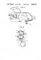
- FIG. 1is a schematic perspective view of a basic embodiment of the arm according to the invention
- FIG. 2shows the arm according to FIG. 1 in a bent position
- FIG. 3is a schematic side view of a robot arm according to the invention composed of two groups of elements and thereby being bendable in two different planes or directions,
- FIG. 4is an elevational, partly perspective and partly sectional view of a complete industrial robot provided with a flexible arm according to the invention
- FIG. 5is a perspective view showing the capability of the robot arm of the invention in reaching around corners etc.
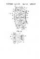
- FIG. 6is an elevation view on a larger scale of a part of the arm according to one embodiment of the invention and the geometry of the elements forming part thereof,
- FIG. 7is a perspective view of a lamella shaped element according to another embodiment of the invention.
- FIG. 8is a cross-sectional view taken along line VIII--VIII in FIG. 7,
- FIG. 9is an elevational view partly in section of an embodiment which can also perform rotational movements
- FIGS. 10 and 11are cross-sectional views through two additional embodiments, showing elements actuated electromagnetically
- FIGS. 12, 13 and 14are cross-sectional views showing further embodiments with hydraulic or pneumatic actuation of the elements
- FIGS. 15 and 16are cross-sectional views through further embodiments of the invention showing combinations of curved and flat contacting surfaces on the elements
- FIG. 17is a cross-sectional view through another embodiment having contacting convex surfaces of different radii.
- FIG. 18is a cross-sectional view of a further embodiment wherein one contacting surface is convex and the other is concave.
- the flexible arm 10fundamentally comprises as shown in the embodiment of FIGS. 1 and 2, a number of elements 11 arranged in series and each being designed as a circular disc with curved contact surfaces.
- each element 11is provided with a number of holes 12 e.g. four holes placed close to the outer edge of the element and on equal distance from each other and from the center of the element, said holes being intended for an equal number of actuating means 14.
- a through-opening 13is arranged in the center of the element. The elements are arranged in abutting contact with each other with the guiding holes 12 being located in substantial alignment.
- the guiding holes 12are counter-sunk, said counter-sinks receiving termination members 15 arranged at the outer ends of the actuating means.
- the actuating means 14consist of cables, wires or the like having good tensile strength. By pulling one or more of the wires 14 projecting outside the last element the robot arm can be bent in all directions. If a bending movement is desired between two actuating means 14, as shown in FIG. 2, these are both subjected to a pull, whereby the bending movement can be more or less displaced toward the first or second means 14 by altering the magnitudes of the pulls.
- the arm 10can thereby also be brought to perform a rotational movement about its longitudinal axis.
- a flexible transmission means 16passes through the central openings 13 in the elements, said transmission means being intended to transmit tensile--compressive--and/or rotational forces to a tool 23 (FIG. 4) or the like arranged at the free end of the arm.
- the elementscan be kept together in groups, where each group is operated with actuating means 14 special for this group.
- the arm according to FIG. 3comprises two groups, a lower group A and an upper group B.
- the elements 11a of the group Aare operated by the actuating means 14a, while the elements 11b of the group B are operated by the actuating means 14b.
- two diametrically opposed actuating members 14a and 14bare actuated as shown with arrows.
- the two groups A and B of the armcan also perform bendings in different planes by appropriate actuation of the means 14a and 14b.
- the armcan of course also be provided with more than two groups of elements, so that it can even be bent 360° or more in different planes or directions if desired.
- FIG. 4is shown a practical application of the arm according to the previous embodiment.
- the flexible arm 10composed by two groups of elements 11a and 11b is connected at one end to a machine unit 17, which contains four servo-motors 18, which drive a winding drum 19 for each actuating means 14a and 14b.
- the motors 18are reversible and controlled so that each actuating means--each wire--14a and 14b can be subjected to an individually adjustable force during the winding on as well as during the unwinding from the winding drum 19.
- Resilient prestressing means 31(FIG. 6) are arranged for the wires 14.
- the flexible transmission means 16is at the lower end of the arm connected to a servo-motor 20 by way of a gear device 21 and an overload protective coupling 22.
- a tool 23is connected to the central transmission means 16 at the free end of the arm, said tool comprising a spray gun fed through a tube 24 from a spray painting device 25.
- the separate elements 11are enclosed in a protective flexible casing 26.
- FIG. 5shows that the arm can be bent in such a way that it can even perform manipulations behind obstacles or in spaces otherwise difficult to reach.
- each element 11'comprises two segment-shaped members 8' and 9' between which a spacing disc 6 is arranged.
- the segments 8' and 9'have each a single curved contact surface 5' and a plane base surface 7, with which the segments abut against a side each of the spacing disc 6.
- the segments 8' and 9'can either be attached to the spacing disc 6 or they can be formed intergral therewith.
- the segments 8' and 9'are arranged in mutually orthogonal planes, which means that every other segment can perform a bending movement in one plane and every other segment a corresponding bending movement in a plane perpendicular to the first mentioned plane.
- thesecan be provided with steering means 4, for example teeth cooperating with corresponding teeth in the adjacent element 11' at the relative movement of the segments.
- the segments 8' and 9'are preferably formed as portions of cylindrical toothed wheels, at which the center of curvature of the single curved contact surface 5 or the center of the pitch circle of the teeth are located outside each element respectively.
- Flat segment portions 3are arranged beside the teeth provided segments 8' and 9' on level with the root of the tooth.
- the modification shown in FIG. 9is developed for making it possible also to transfer rotational movements by way of the elements, which for this purpose are provided with radial teeth 35 on the curved surfaces facing each other, said teeth engaging each other independent of which angular positions the elements take.
- the elementsIn order to permit the rotational movement of the elements its flanges 30 with openings 12 for the wires 14 are rotatable relative to the element member, which has been achieved by arranging a bearing 36 between these parts.
- a motor 20the elements can in this way transfer rotational movements to the free end of the arm and to the tool 23 without in any way impairing the flexibility of the arm.
- wire cable-shaped actuating means 14which only have a connecting function, with electromagnetic or hydraulic servo-motors.
- FIG. 10shows a modification with electromagnetic adjustment of the angular position of the elements relative to each other, whereby between each flange 30 are pivotally mounted electromagnets 39, which are arranged to adjust the distance between the elements.
- Each electromagnetcan possibly be individually actuated for providing the highest possible moveability and flexibility.
- each non-moveable electromagnet 40has its poles facing each other and in order to achiefe a variable bending of the arm several such bar shaped magnets can be arranged in a radial pattern in the elements.
- Electromagnetic actuating meansusually work only between two fixed end positions, whereby a stepless adjustment of the bending of the arm is impossible.
- the actuating meanscomprises hydraulic or pneumatic servo-motors in the form of cylinders 42 with double opposed pistons 43.
- the pressure mediumcan be supplied from a feed tube 45 (not shown) through a central inlet or outlet 44.
- the pistons 43are pivotally mounted at the peripheral flange 30 of the elements.
- the feed tube 45is preferably passed through apertures (not shown) in the flange 30.
- FIG. 13is shown an embodiment wherein the elements 11"" are divided into two parts along peripheral flanges and where each part 37 and 38 is provided with a peripheral flange 30'.
- Servomotors 32are arranged between these two parts 37 and 38 in such a way that the two parts can be moved into different relative inclined positions.
- the servomotors 32consist of shortstroke hydraulic or pneumatic motors, for example piston cylinder devices or bellows actuated by a pressure medium. At least three such motors are arranged at equal distances from each other and conduits 45 cupply them with pressure medium.
- FIG. 14A further embodiment where the elements are actuated by hydraulic or pneumatic means is shown in FIG. 14.
- a number of pressure tubes 46 with radially projecting pressure lips 47are arranged to operate between peripheral flanges 30" of the elements. When a pressure is supplied in the tube 46 the pressure lips 47 will expand and displace the flanges 30" of the elements from each other.
- the tubes 46can be an integral portion of the casing 26 of the arm 10 shown in FIG. 4.
- FIGS. 15, 16, 17 and 18show further embodiments of the invention wherein the elements have different curved surface configurations or cooperate with additional members having a plane surface, or surfaces.
- the elementsare shown only schematically to illustrate only the cross-sectional configuration of the elements, such as in FIGS. 10, 11 and 12, but it is to be understood that these embodiments are intended to be used in the same manner as the previously described embodiments and although holes comparable to 12 and 13, or actuating means 14, 20, 32, 39, 40, 41, 45, 46, etc., and cooperating structural members are not shown, these further embodiments may be provided with these other features of the invention in accordance with the specific actuators, or combinations thereof, desired.
- FIG. 15is shown the embodiment wherein a disc 50 having plane or flat surfaces 52 on opposite sides is interposed between adjacent elements 51 so that the curved surfaces of elements 51 have rolling contact on the plane surfaces.
- the adjacent members 50, 51can be regarded as the elements of a robot arm wherein the adjacent elements have curved and flat surfaces respectively in rolling engagement with each other. This design provides a higher rigidity in use than the embodiments utilizing elements having oppositely curved convex contacting surfaces.
- FIG. 16shows the embodiment similar to FIG. 15 but wherein the elements 51' each have one convex curved surface 53 and one plane or flat surface 54 on opposite sides thereof. The curved surface of each element engages the flat surface of the adjacent element.
- FIG. 17is shown the embodiment wherein adjacent elements 55, 56 have contacting convex surfaces 57, 58 having different radii (see r in FIG. 6) of curvature to provide a different degree of flexibility.
- FIG. 18shows an embodiment wherein adjacent elements 59, 60 have convex and concave contacting surfaces, 61 and 62 respectively, for greater rigidity.
Landscapes
- Engineering & Computer Science (AREA)
- Robotics (AREA)
- Mechanical Engineering (AREA)
- Manipulator (AREA)
Abstract
Description
Claims (6)
Priority Applications (1)
| Application Number | Priority Date | Filing Date | Title |
|---|---|---|---|
| US06/426,964US4494417A (en) | 1979-03-16 | 1982-09-29 | Flexible arm, particularly a robot arm |
Applications Claiming Priority (3)
| Application Number | Priority Date | Filing Date | Title |
|---|---|---|---|
| SE7902366 | 1979-03-16 | ||
| SE7902366ASE419421B (en) | 1979-03-16 | 1979-03-16 | RESIDENTIAL ARM IN SPECIAL ROBOT ARM |
| US06/426,964US4494417A (en) | 1979-03-16 | 1982-09-29 | Flexible arm, particularly a robot arm |
Related Parent Applications (1)
| Application Number | Title | Priority Date | Filing Date |
|---|---|---|---|
| US06/351,589Continuation-In-PartUS4393728A (en) | 1979-03-16 | 1982-02-23 | Flexible arm, particularly a robot arm |
Publications (1)
| Publication Number | Publication Date |
|---|---|
| US4494417Atrue US4494417A (en) | 1985-01-22 |
Family
ID=26657222
Family Applications (1)
| Application Number | Title | Priority Date | Filing Date |
|---|---|---|---|
| US06/426,964Expired - Fee RelatedUS4494417A (en) | 1979-03-16 | 1982-09-29 | Flexible arm, particularly a robot arm |
Country Status (1)
| Country | Link |
|---|---|
| US (1) | US4494417A (en) |
Cited By (135)
| Publication number | Priority date | Publication date | Assignee | Title |
|---|---|---|---|---|
| US4621965A (en)* | 1983-02-10 | 1986-11-11 | United Kingdom Atomic Energy Authority | Manipulators |
| US4683773A (en)* | 1985-06-27 | 1987-08-04 | Gary Diamond | Robotic device |
| US4712969A (en)* | 1983-08-29 | 1987-12-15 | Kabushiki Kaisha Toshiba | Expandable and contractable arms |
| US4739692A (en)* | 1984-05-29 | 1988-04-26 | Fluidic Motion Corporation | Liquid contractility actuator |
| US4765795A (en)* | 1986-06-10 | 1988-08-23 | Lord Corporation | Object manipulator |
| US4784042A (en)* | 1986-02-12 | 1988-11-15 | Nathaniel A. Hardin | Method and system employing strings of opposed gaseous-fluid inflatable tension actuators in jointed arms, legs, beams and columns for controlling their movements |
| US4815911A (en)* | 1982-07-05 | 1989-03-28 | Komatsu, Ltd. | Device for torsion-proof connection of an element in a robot arm or the like |
| US4848179A (en)* | 1988-02-16 | 1989-07-18 | Trw Inc. | Flexidigit robotic manipulator |
| US4911033A (en)* | 1989-01-03 | 1990-03-27 | Ross-Hime Designs, Incorporated | Robotic manipulator |
| US4932806A (en)* | 1989-03-21 | 1990-06-12 | The United States Of America As Represented By The Administrator Of The National Aeronautics And Space Administration | Compliant joint |
| US4954952A (en)* | 1988-02-16 | 1990-09-04 | Trw Inc. | Robotic arm systems |
| US4977790A (en)* | 1987-03-23 | 1990-12-18 | Kabushiki Kaisha Komatsu Seisakusho | Flexible arm |
| US5021798A (en)* | 1988-02-16 | 1991-06-04 | Trw Inc. | Antenna with positionable reflector |
| US5079999A (en)* | 1989-06-23 | 1992-01-14 | Bridgestone Corporation | Bendable actuator |
| US5129279A (en)* | 1991-02-28 | 1992-07-14 | Rennex Brian G | Flexible robotic limb |
| WO1993006974A1 (en)* | 1991-10-10 | 1993-04-15 | Siemens Aktiengesellschaft | Flexible robot arm |
| US5297443A (en)* | 1992-07-07 | 1994-03-29 | Wentz John D | Flexible positioning appendage |
| US5317952A (en)* | 1991-11-22 | 1994-06-07 | Kinetic Sciences Inc. | Tentacle-like manipulators with adjustable tension lines |
| US5365156A (en)* | 1993-10-27 | 1994-11-15 | Crook James C | Force transducer for a robotic arm |
| US5560258A (en)* | 1993-01-08 | 1996-10-01 | Fmc Corporation | Release mechanism for use with a remote tool |
| US5620352A (en)* | 1996-03-29 | 1997-04-15 | Tzong; Chun-Chuen | Flexible tube having a number of joints |
| US5632432A (en)* | 1994-12-19 | 1997-05-27 | Ethicon Endo-Surgery, Inc. | Surgical instrument |
| US5752644A (en)* | 1995-07-11 | 1998-05-19 | United States Surgical Corporation | Disposable loading unit for surgical stapler |
| WO2001060214A2 (en) | 2000-02-15 | 2001-08-23 | The Procter & Gamble Company | Active change aids for external articles |
| US6458010B1 (en)* | 1999-02-19 | 2002-10-01 | Sony Corporation | Curving mechanism and robot |
| US20030116167A1 (en)* | 2001-12-21 | 2003-06-26 | Kimberly-Clark Worldwide, Inc. | Respiratory circuit support arm |
| RU2226165C2 (en)* | 2002-05-17 | 2004-03-27 | Институт механики Уфимского научного центра РАН | Method of raising sunken object and system for realization of this method |
| US6773327B1 (en)* | 2002-02-12 | 2004-08-10 | Hasbro, Inc. | Apparatus for actuating a toy |
| US20040195988A1 (en)* | 2001-06-13 | 2004-10-07 | Buckingham Robert Oliver | Link assembly for a snake like robot arm |
| US6843703B1 (en) | 2003-04-30 | 2005-01-18 | Hasbro, Inc. | Electromechanical toy |
| US20050020901A1 (en)* | 2000-04-03 | 2005-01-27 | Neoguide Systems, Inc., A Delaware Corporation | Apparatus and methods for facilitating treatment of tissue via improved delivery of energy based and non-energy based modalities |
| US6858005B2 (en) | 2000-04-03 | 2005-02-22 | Neo Guide Systems, Inc. | Tendon-driven endoscope and methods of insertion |
| USRE38708E1 (en) | 1995-07-11 | 2005-03-01 | United States Surgical Corporation | Disposable loading unit for surgical stapler |
| US20050154258A1 (en)* | 2000-04-03 | 2005-07-14 | Tartaglia Joseph M. | Endoscope with adjacently positioned guiding apparatus |
| US20050222498A1 (en)* | 2000-04-03 | 2005-10-06 | Amir Belson | Steerable endoscope and improved method of insertion |
| EP1586778A3 (en)* | 2001-12-13 | 2006-02-01 | Seiko Epson Corporation | Flexible actuator |
| US20060052664A1 (en)* | 2000-04-03 | 2006-03-09 | Julian Christopher A | Connector device for a controllable instrument |
| US20060106487A1 (en)* | 2004-10-05 | 2006-05-18 | Allen Robert M | Programmable load forming system, components thereof, and methods of use |
| US20060156851A1 (en)* | 2004-12-02 | 2006-07-20 | Jacobsen Stephen C | Mechanical serpentine device |
| US20060235458A1 (en)* | 2005-04-15 | 2006-10-19 | Amir Belson | Instruments having an external working channel |
| US20060258912A1 (en)* | 2000-04-03 | 2006-11-16 | Amir Belson | Activated polymer articulated instruments and methods of insertion |
| US20070135803A1 (en)* | 2005-09-14 | 2007-06-14 | Amir Belson | Methods and apparatus for performing transluminal and other procedures |
| US20070161291A1 (en)* | 2005-11-23 | 2007-07-12 | Neoguide Systems, Inc. | Non-metallic, multi-strand control cable for steerable instruments |
| US20070249901A1 (en)* | 2003-03-07 | 2007-10-25 | Ohline Robert M | Instrument having radio frequency identification systems and methods for use |
| US20070270650A1 (en)* | 2006-05-19 | 2007-11-22 | Robert Eno | Methods and apparatus for displaying three-dimensional orientation of a steerable distal tip of an endoscope |
| US20080136254A1 (en)* | 2006-11-13 | 2008-06-12 | Jacobsen Stephen C | Versatile endless track for lightweight mobile robots |
| US20080154288A1 (en)* | 2002-01-09 | 2008-06-26 | Neoguide Systems, Inc. | Apparatus and method for endoscopic colectomy |
| US20080164079A1 (en)* | 2006-11-13 | 2008-07-10 | Jacobsen Stephen C | Serpentine robotic crawler |
| US20080167752A1 (en)* | 2006-11-13 | 2008-07-10 | Jacobsen Stephen C | Tracked robotic crawler having a moveable arm |
| US20080215185A1 (en)* | 2006-11-13 | 2008-09-04 | Jacobsen Stephen C | Unmanned ground robotic vehicle having an alternatively extendible and retractable sensing appendage |
| US20080281468A1 (en)* | 2007-05-08 | 2008-11-13 | Raytheon Sarcos, Llc | Variable primitive mapping for a robotic crawler |
| US20090030562A1 (en)* | 2007-07-10 | 2009-01-29 | Jacobsen Stephen C | Modular Robotic Crawler |
| US20090025988A1 (en)* | 2007-07-10 | 2009-01-29 | Jacobsen Stephen C | Serpentine Robotic Crawler Having A Continuous Track |
| US20090095112A1 (en)* | 2001-06-13 | 2009-04-16 | Robert Oliver Buckingham | Link Assembly With Defined Boundaries For A Snake Like Robot Arm |
| US20090216083A1 (en)* | 2008-02-25 | 2009-08-27 | Neoguide Systems, Inc. | Systems and Methods for Articulating an Elongate Body |
| US20090222133A1 (en)* | 2001-06-13 | 2009-09-03 | Robert Oliver Buckingham | System and Method for Controlling a Robotic Arm |
| US20090248042A1 (en)* | 2008-03-27 | 2009-10-01 | Kirschenman Mark B | Model catheter input device |
| US20100030377A1 (en)* | 2006-05-24 | 2010-02-04 | John Unsworth | Snaking Robotic Arm with Movable Shapers |
| WO2010001114A3 (en)* | 2008-06-30 | 2010-03-04 | Oliver Crispin Robotics Limited | Robotic arm |
| US7695341B1 (en) | 2002-11-27 | 2010-04-13 | Hasbro, Inc. | Electromechanical toy |
| US20100174422A1 (en)* | 2009-01-08 | 2010-07-08 | Jacobsen Stephen C | Point And Go Navigation System And Method |
| US20100175496A1 (en)* | 2009-01-14 | 2010-07-15 | Samsung Electronics Co., Ltd. | Robot |
| US20100201185A1 (en)* | 2006-11-13 | 2010-08-12 | Raytheon Sarcos, Llc | Conformable Track Assembly For A Robotic Crawler |
| US20100242659A1 (en)* | 2006-08-23 | 2010-09-30 | Takashi Saito | Manipulator mechanism |
| US20100317244A1 (en)* | 2009-06-11 | 2010-12-16 | Jacobsen Stephen C | Amphibious Robotic Crawler |
| US20100318242A1 (en)* | 2009-06-11 | 2010-12-16 | Jacobsen Stephen C | Method And System For Deploying A Surveillance Network |
| US20110065993A1 (en)* | 2000-04-03 | 2011-03-17 | Amir Belson | Steerable segmented endoscope and method of insertion |
| US8002716B2 (en) | 2007-05-07 | 2011-08-23 | Raytheon Company | Method for manufacturing a complex structure |
| US8393422B1 (en) | 2012-05-25 | 2013-03-12 | Raytheon Company | Serpentine robotic crawler |
| US20130091974A1 (en)* | 2010-05-31 | 2013-04-18 | Commissariat A L'energie Atomique Et Aux Energies Alternatives | Articulated inflatable structure and robot arm comprising such a structure |
| US20130199327A1 (en)* | 2012-02-06 | 2013-08-08 | Samsung Electronics Co., Ltd. | Link unit, arm module, and surgical apparatus including the same |
| CN103358304A (en)* | 2012-04-02 | 2013-10-23 | 三星电子株式会社 | Robot arm driving apparatus and robot arm having same |
| US8578810B2 (en)* | 2011-02-14 | 2013-11-12 | Intuitive Surgical Operations, Inc. | Jointed link structures exhibiting preferential bending, and related methods |
| US20130312564A1 (en)* | 2012-05-25 | 2013-11-28 | Samsung Electronics Co., Ltd. | Arm unit and robot having the same |
| WO2014126482A2 (en) | 2013-02-14 | 2014-08-21 | Paul Weber | Systems, apparatus and methods for tissue dissection |
| US8968301B2 (en) | 2012-12-31 | 2015-03-03 | Tdm Surgitech, Inc. | Apparatus, systems and methods for tissue dissection and modification |
| US8992421B2 (en) | 2010-10-22 | 2015-03-31 | Medrobotics Corporation | Highly articulated robotic probes and methods of production and use of such probes |
| US20150122071A1 (en)* | 2013-11-05 | 2015-05-07 | Samsung Electronics Co., Ltd. | Actuator and manipulator including the same |
| US20150122073A1 (en)* | 2012-06-01 | 2015-05-07 | Aldebaran Robotics | Spinal column for a humanoid robot |
| US9031698B2 (en) | 2012-10-31 | 2015-05-12 | Sarcos Lc | Serpentine robotic crawler |
| US9220398B2 (en) | 2007-10-11 | 2015-12-29 | Intuitive Surgical Operations, Inc. | System for managing Bowden cables in articulating instruments |
| US9364955B2 (en) | 2011-12-21 | 2016-06-14 | Medrobotics Corporation | Stabilizing apparatus for highly articulated probes with link arrangement, methods of formation thereof, and methods of use thereof |
| US9393501B2 (en)* | 2014-01-22 | 2016-07-19 | Chau King Sze | Power module and construction toy having a power module |
| US9409292B2 (en) | 2013-09-13 | 2016-08-09 | Sarcos Lc | Serpentine robotic crawler for performing dexterous operations |
| ITUB20152049A1 (en)* | 2015-07-13 | 2017-01-13 | Marco Ceccarelli | Artificial torso for humanoid robot |
| US9566711B2 (en) | 2014-03-04 | 2017-02-14 | Sarcos Lc | Coordinated robotic control |
| US9572628B2 (en) | 2011-09-13 | 2017-02-21 | Medrobotics Corporation | Highly articulated probes with anti-twist link arrangement, methods of formation thereof, and methods of performing medical procedures |
| US9624911B1 (en) | 2012-10-26 | 2017-04-18 | Sunfolding, Llc | Fluidic solar actuator |
| US9649163B2 (en) | 2010-11-11 | 2017-05-16 | Medrobotics Corporation | Introduction devices for highly articulated robotic probes and methods of production and use of such probes |
| US9675380B2 (en) | 2012-08-09 | 2017-06-13 | Medrobotics Corporation | Surgical tool positioning system |
| US9795447B2 (en) | 2008-03-27 | 2017-10-24 | St. Jude Medical, Atrial Fibrillation Division, Inc. | Robotic catheter device cartridge |
| US9861786B2 (en)* | 2004-06-07 | 2018-01-09 | Intuitive Surgical Operations, Inc. | Articulating mechanism with flex hinged links |
| US9888973B2 (en) | 2010-03-31 | 2018-02-13 | St. Jude Medical, Atrial Fibrillation Division, Inc. | Intuitive user interface control for remote catheter navigation and 3D mapping and visualization systems |
| US9901410B2 (en) | 2010-07-28 | 2018-02-27 | Medrobotics Corporation | Surgical positioning and support system |
| US9913695B2 (en) | 2013-05-02 | 2018-03-13 | Medrobotics Corporation | Robotic system including a cable interface assembly |
| US20180154515A1 (en)* | 2016-12-02 | 2018-06-07 | Rolls-Royce Plc | Hyper redundant robots |
| US10004568B2 (en) | 2013-12-30 | 2018-06-26 | Medrobotics Corporation | Articulating robotic probes |
| US10045761B2 (en) | 2012-12-31 | 2018-08-14 | Tdm Surgitech, Inc. | Systems, apparatus and methods for tissue dissection |
| US10071303B2 (en) | 2015-08-26 | 2018-09-11 | Malibu Innovations, LLC | Mobilized cooler device with fork hanger assembly |
| US10135388B2 (en) | 2015-01-30 | 2018-11-20 | Sunfolding, Inc. | Fluidic actuator system and method |
| US10231788B2 (en) | 2008-03-27 | 2019-03-19 | St. Jude Medical, Atrial Fibrillation Division, Inc. | Robotic catheter system |
| US10357322B2 (en) | 2009-07-22 | 2019-07-23 | St. Jude Medical, Atrial Fibrillation Division, Inc. | System and method for controlling a remote medical device guidance system in three-dimensions using gestures |
| ES2721785A1 (en)* | 2018-02-02 | 2019-08-05 | Perez Daniel Cortavitarte | Extendable and articulated rotary head of pressurized air spray gun (Machine-translation by Google Translate, not legally binding) |
| US10406571B2 (en) | 2016-03-08 | 2019-09-10 | Alexander G. Innes | Mechanical extended reach Sluicer |
| US10426557B2 (en) | 2008-03-27 | 2019-10-01 | St. Jude Medical, Atrial Fibrillation Division, Inc. | System and method of automatic detection of obstructions for a robotic catheter system |
| EP2961577B1 (en)* | 2013-02-26 | 2019-11-06 | Ahmad Kamal Bakir | Manipulator arm module |
| US10500373B2 (en) | 2015-12-04 | 2019-12-10 | Project Moray, Inc. | Lateral articulation anchors for catheters and other uses |
| US10512757B2 (en) | 2016-03-25 | 2019-12-24 | Project Moray, Inc. | Fluid-actuated sheath displacement and articulation behavior improving systems, devices, and methods for catheters, continuum manipulators, and other uses |
| US10512392B2 (en) | 2008-02-06 | 2019-12-24 | Intuitive Surgical Operations, Inc. | Segmented instrument having braking capabilities |
| US10525233B2 (en) | 2015-12-04 | 2020-01-07 | Project Moray, Inc. | Input and articulation system for catheters and other uses |
| USD874655S1 (en) | 2018-01-05 | 2020-02-04 | Medrobotics Corporation | Positioning arm for articulating robotic surgical system |
| US10562180B2 (en) | 2016-03-29 | 2020-02-18 | Other Lab, Llc | Fluidic robotic actuator system and method |
| US10646696B2 (en) | 2015-03-27 | 2020-05-12 | Project Moray, Inc. | Articulation systems, devices, and methods for catheters and other uses |
| US10786905B1 (en) | 2018-04-16 | 2020-09-29 | AGI Engineering, Inc. | Tank excavator |
| US10807659B2 (en) | 2016-05-27 | 2020-10-20 | Joseph L. Pikulski | Motorized platforms |
| US10806899B2 (en) | 2016-02-17 | 2020-10-20 | Project Moray, Inc. | Local contraction of flexible bodies using balloon expansion for extension-contraction catheter articulation and other uses |
| US10814102B2 (en) | 2016-09-28 | 2020-10-27 | Project Moray, Inc. | Base station, charging station, and/or server for robotic catheter systems and other uses, and improved articulated devices and systems |
| US10864640B1 (en) | 2017-12-26 | 2020-12-15 | AGI Engineering, Inc. | Articulating arm programmable tank cleaning nozzle |
| US10905861B2 (en) | 2017-04-25 | 2021-02-02 | Project Moray, Inc. | Matrix supported balloon articulation systems, devices, and methods for catheters and other uses |
| US10917038B2 (en) | 2017-04-17 | 2021-02-09 | Sunfolding, Inc. | Pneumatic actuator system and method |
| CN112719844A (en)* | 2021-01-23 | 2021-04-30 | 李春梅 | Wall-mounted electronic product assembling and producing device and assembling and producing method |
| US11031149B1 (en) | 2018-02-13 | 2021-06-08 | AGI Engineering, Inc. | Nuclear abrasive slurry waste pump with backstop and macerator |
| US11096563B2 (en) | 2005-11-22 | 2021-08-24 | Intuitive Surgical Operations, Inc. | Method of determining the shape of a bendable instrument |
| US11267024B2 (en) | 2018-06-11 | 2022-03-08 | AGI Engineering, Inc. | Programmable tank cleaning nozzle |
| US11311920B2 (en) | 2018-06-11 | 2022-04-26 | AGI Engineering, Inc. | Programmable railcar tank cleaning system |
| US11369432B2 (en) | 2016-09-28 | 2022-06-28 | Project Moray, Inc. | Arrhythmia diagnostic and/or therapy delivery methods and devices, and robotic systems for other uses |
| CN114683222A (en)* | 2020-12-31 | 2022-07-01 | 北京晓聪科技有限公司 | Device with handle |
| US11413666B1 (en) | 2018-02-13 | 2022-08-16 | AGI Engineering, Inc. | Vertical travel robotic tank cleaning system |
| US11420021B2 (en) | 2016-03-25 | 2022-08-23 | Project Moray, Inc. | Fluid-actuated displacement for catheters, continuum manipulators, and other uses |
| US11502639B2 (en) | 2018-05-29 | 2022-11-15 | Sunfolding, Inc. | Tubular fluidic actuator system and method |
| US11571723B1 (en) | 2019-03-29 | 2023-02-07 | AGI Engineering, Inc. | Mechanical dry waste excavating end effector |
| US11577287B1 (en) | 2018-04-16 | 2023-02-14 | AGI Engineering, Inc. | Large riser extended reach sluicer and tool changer |
| US11683003B2 (en) | 2020-06-22 | 2023-06-20 | Sunfolding, Inc. | Locking, dampening and actuation systems and methods for solar trackers |
| US20240173850A1 (en)* | 2022-11-26 | 2024-05-30 | Signetron Inc. | Robotic payload for extracting and depositing lightweight materials |
| US12311550B2 (en) | 2020-12-31 | 2025-05-27 | Sarcos Corp. | Smart control system for a robotic device |
Citations (11)
| Publication number | Priority date | Publication date | Assignee | Title |
|---|---|---|---|---|
| US2241576A (en)* | 1940-03-20 | 1941-05-13 | Charles L Barton | Figure toy |
| US2421279A (en)* | 1943-03-25 | 1947-05-27 | Emanuel Merian | Body with movable parts |
| US3060972A (en)* | 1957-08-22 | 1962-10-30 | Bausch & Lomb | Flexible tube structures |
| US3190286A (en)* | 1961-10-31 | 1965-06-22 | Bausch & Lomb | Flexible viewing probe for endoscopic use |
| US3266059A (en)* | 1963-06-19 | 1966-08-16 | North American Aviation Inc | Prestressed flexible joint for mechanical arms and the like |
| US3284964A (en)* | 1964-03-26 | 1966-11-15 | Saito Norio | Flexible beam structures |
| US3497083A (en)* | 1968-05-10 | 1970-02-24 | Us Navy | Tensor arm manipulator |
| US3546961A (en)* | 1967-12-22 | 1970-12-15 | Gen Electric | Variable flexibility tether |
| US3623566A (en)* | 1969-11-14 | 1971-11-30 | Arthur Orloff | Undulating body propulsion system |
| US3927899A (en)* | 1974-03-22 | 1975-12-23 | Trw Inc | Vehicle steering apparatus |
| US4151757A (en)* | 1977-03-24 | 1979-05-01 | Societe Anonyme des Equipements S.E.I.M. Specialites Electriques et Industrielles et Mechaniques | Electric device for controlling the position of a member such as the external rearview mirror member of an automotive-vehicle |
- 1982
- 1982-09-29USUS06/426,964patent/US4494417A/ennot_activeExpired - Fee Related
Patent Citations (11)
| Publication number | Priority date | Publication date | Assignee | Title |
|---|---|---|---|---|
| US2241576A (en)* | 1940-03-20 | 1941-05-13 | Charles L Barton | Figure toy |
| US2421279A (en)* | 1943-03-25 | 1947-05-27 | Emanuel Merian | Body with movable parts |
| US3060972A (en)* | 1957-08-22 | 1962-10-30 | Bausch & Lomb | Flexible tube structures |
| US3190286A (en)* | 1961-10-31 | 1965-06-22 | Bausch & Lomb | Flexible viewing probe for endoscopic use |
| US3266059A (en)* | 1963-06-19 | 1966-08-16 | North American Aviation Inc | Prestressed flexible joint for mechanical arms and the like |
| US3284964A (en)* | 1964-03-26 | 1966-11-15 | Saito Norio | Flexible beam structures |
| US3546961A (en)* | 1967-12-22 | 1970-12-15 | Gen Electric | Variable flexibility tether |
| US3497083A (en)* | 1968-05-10 | 1970-02-24 | Us Navy | Tensor arm manipulator |
| US3623566A (en)* | 1969-11-14 | 1971-11-30 | Arthur Orloff | Undulating body propulsion system |
| US3927899A (en)* | 1974-03-22 | 1975-12-23 | Trw Inc | Vehicle steering apparatus |
| US4151757A (en)* | 1977-03-24 | 1979-05-01 | Societe Anonyme des Equipements S.E.I.M. Specialites Electriques et Industrielles et Mechaniques | Electric device for controlling the position of a member such as the external rearview mirror member of an automotive-vehicle |
Cited By (239)
| Publication number | Priority date | Publication date | Assignee | Title |
|---|---|---|---|---|
| US4815911A (en)* | 1982-07-05 | 1989-03-28 | Komatsu, Ltd. | Device for torsion-proof connection of an element in a robot arm or the like |
| US4621965A (en)* | 1983-02-10 | 1986-11-11 | United Kingdom Atomic Energy Authority | Manipulators |
| US4712969A (en)* | 1983-08-29 | 1987-12-15 | Kabushiki Kaisha Toshiba | Expandable and contractable arms |
| US4739692A (en)* | 1984-05-29 | 1988-04-26 | Fluidic Motion Corporation | Liquid contractility actuator |
| US4683773A (en)* | 1985-06-27 | 1987-08-04 | Gary Diamond | Robotic device |
| US4784042A (en)* | 1986-02-12 | 1988-11-15 | Nathaniel A. Hardin | Method and system employing strings of opposed gaseous-fluid inflatable tension actuators in jointed arms, legs, beams and columns for controlling their movements |
| US4765795A (en)* | 1986-06-10 | 1988-08-23 | Lord Corporation | Object manipulator |
| US4977790A (en)* | 1987-03-23 | 1990-12-18 | Kabushiki Kaisha Komatsu Seisakusho | Flexible arm |
| US4954952A (en)* | 1988-02-16 | 1990-09-04 | Trw Inc. | Robotic arm systems |
| US4848179A (en)* | 1988-02-16 | 1989-07-18 | Trw Inc. | Flexidigit robotic manipulator |
| US5021798A (en)* | 1988-02-16 | 1991-06-04 | Trw Inc. | Antenna with positionable reflector |
| US4911033A (en)* | 1989-01-03 | 1990-03-27 | Ross-Hime Designs, Incorporated | Robotic manipulator |
| WO1990007403A1 (en)* | 1989-01-03 | 1990-07-12 | Ross-Hime Designs, Incorporated | Robotic manipulator |
| US4932806A (en)* | 1989-03-21 | 1990-06-12 | The United States Of America As Represented By The Administrator Of The National Aeronautics And Space Administration | Compliant joint |
| US5079999A (en)* | 1989-06-23 | 1992-01-14 | Bridgestone Corporation | Bendable actuator |
| US5129279A (en)* | 1991-02-28 | 1992-07-14 | Rennex Brian G | Flexible robotic limb |
| WO1993006974A1 (en)* | 1991-10-10 | 1993-04-15 | Siemens Aktiengesellschaft | Flexible robot arm |
| US5469756A (en)* | 1991-10-10 | 1995-11-28 | Siemens Aktiengesellschaft | Flexible robot arm |
| US5317952A (en)* | 1991-11-22 | 1994-06-07 | Kinetic Sciences Inc. | Tentacle-like manipulators with adjustable tension lines |
| US5297443A (en)* | 1992-07-07 | 1994-03-29 | Wentz John D | Flexible positioning appendage |
| US5560258A (en)* | 1993-01-08 | 1996-10-01 | Fmc Corporation | Release mechanism for use with a remote tool |
| US5365156A (en)* | 1993-10-27 | 1994-11-15 | Crook James C | Force transducer for a robotic arm |
| US5673841A (en)* | 1994-12-19 | 1997-10-07 | Ethicon Endo-Surgery, Inc. | Surgical instrument |
| US5632432A (en)* | 1994-12-19 | 1997-05-27 | Ethicon Endo-Surgery, Inc. | Surgical instrument |
| US5669544A (en)* | 1994-12-19 | 1997-09-23 | Ethicon Endo-Surgery, Inc. | Surgical instrument |
| US5673840A (en)* | 1994-12-19 | 1997-10-07 | Ethicon Endo-Surgery, Inc. | Surgical instrument |
| US5680982A (en)* | 1994-12-19 | 1997-10-28 | Ethicon Endo-Surgery, Inc. | Surgical instrument |
| US5692668A (en)* | 1994-12-19 | 1997-12-02 | Ethicon Endo-Surgery, Inc. | Surgical instrument |
| US5826776A (en)* | 1994-12-19 | 1998-10-27 | Ethicon Endo-Surgery, Inc. | Surgical instrument |
| US5752644A (en)* | 1995-07-11 | 1998-05-19 | United States Surgical Corporation | Disposable loading unit for surgical stapler |
| US5911353A (en)* | 1995-07-11 | 1999-06-15 | United States Surgical Corporation | Disposable loading unit for surgical stapler |
| USRE38708E1 (en) | 1995-07-11 | 2005-03-01 | United States Surgical Corporation | Disposable loading unit for surgical stapler |
| US5620352A (en)* | 1996-03-29 | 1997-04-15 | Tzong; Chun-Chuen | Flexible tube having a number of joints |
| US6458010B1 (en)* | 1999-02-19 | 2002-10-01 | Sony Corporation | Curving mechanism and robot |
| WO2001060214A2 (en) | 2000-02-15 | 2001-08-23 | The Procter & Gamble Company | Active change aids for external articles |
| US20050020901A1 (en)* | 2000-04-03 | 2005-01-27 | Neoguide Systems, Inc., A Delaware Corporation | Apparatus and methods for facilitating treatment of tissue via improved delivery of energy based and non-energy based modalities |
| US8827894B2 (en) | 2000-04-03 | 2014-09-09 | Intuitive Surgical Operations, Inc. | Steerable endoscope and improved method of insertion |
| US8062212B2 (en) | 2000-04-03 | 2011-11-22 | Intuitive Surgical Operations, Inc. | Steerable endoscope and improved method of insertion |
| US9427282B2 (en) | 2000-04-03 | 2016-08-30 | Intuitive Surgical Operations, Inc. | Apparatus and methods for facilitating treatment of tissue via improved delivery of energy based and non-energy based modalities |
| US20110065993A1 (en)* | 2000-04-03 | 2011-03-17 | Amir Belson | Steerable segmented endoscope and method of insertion |
| US6858005B2 (en) | 2000-04-03 | 2005-02-22 | Neo Guide Systems, Inc. | Tendon-driven endoscope and methods of insertion |
| US12076102B2 (en) | 2000-04-03 | 2024-09-03 | Intuitive Surgical Operations, Inc. | Connector device for a controllable instrument |
| US20050154258A1 (en)* | 2000-04-03 | 2005-07-14 | Tartaglia Joseph M. | Endoscope with adjacently positioned guiding apparatus |
| US20050154261A1 (en)* | 2000-04-03 | 2005-07-14 | Ohline Robert M. | Tendon-driven endoscope and methods of insertion |
| US20050222498A1 (en)* | 2000-04-03 | 2005-10-06 | Amir Belson | Steerable endoscope and improved method of insertion |
| US11026564B2 (en) | 2000-04-03 | 2021-06-08 | Intuitive Surgical Operations, Inc. | Apparatus and methods for facilitating treatment of tissue via improved delivery of energy based and non-energy based modalities |
| US20060052664A1 (en)* | 2000-04-03 | 2006-03-09 | Julian Christopher A | Connector device for a controllable instrument |
| US9138132B2 (en) | 2000-04-03 | 2015-09-22 | Intuitive Surgical Operations, Inc. | Steerable endoscope and improved method of insertion |
| US10893794B2 (en) | 2000-04-03 | 2021-01-19 | Intuitive Surgical Operations, Inc. | Steerable endoscope and improved method of insertion |
| US9808140B2 (en) | 2000-04-03 | 2017-11-07 | Intuitive Surgical Operations, Inc. | Steerable segmented endoscope and method of insertion |
| US10105036B2 (en) | 2000-04-03 | 2018-10-23 | Intuitive Surgical Operations, Inc. | Connector device for a controllable instrument |
| US10327625B2 (en) | 2000-04-03 | 2019-06-25 | Intuitive Surgical Operations, Inc. | Apparatus and methods for facilitating treatment of tissue via improved delivery of energy based and non-energy based modalities |
| US10736490B2 (en) | 2000-04-03 | 2020-08-11 | Intuitive Surgical Operations, Inc. | Connector device for a controllable instrument |
| US20060258912A1 (en)* | 2000-04-03 | 2006-11-16 | Amir Belson | Activated polymer articulated instruments and methods of insertion |
| US8517923B2 (en) | 2000-04-03 | 2013-08-27 | Intuitive Surgical Operations, Inc. | Apparatus and methods for facilitating treatment of tissue via improved delivery of energy based and non-energy based modalities |
| US8888688B2 (en) | 2000-04-03 | 2014-11-18 | Intuitive Surgical Operations, Inc. | Connector device for a controllable instrument |
| US8845524B2 (en) | 2000-04-03 | 2014-09-30 | Intuitive Surgical Operations, Inc. | Steerable segmented endoscope and method of insertion |
| US8834354B2 (en) | 2000-04-03 | 2014-09-16 | Intuitive Surgical Operations, Inc. | Steerable endoscope and improved method of insertion |
| US8641602B2 (en) | 2000-04-03 | 2014-02-04 | Intuitive Surgical Operations, Inc. | Steerable endoscope and improved method of insertion |
| US8721530B2 (en) | 2000-04-03 | 2014-05-13 | Intuitive Surgical Operations, Inc. | Tendon-driven endoscope and methods of use |
| US20090095112A1 (en)* | 2001-06-13 | 2009-04-16 | Robert Oliver Buckingham | Link Assembly With Defined Boundaries For A Snake Like Robot Arm |
| US20040195988A1 (en)* | 2001-06-13 | 2004-10-07 | Buckingham Robert Oliver | Link assembly for a snake like robot arm |
| US8205522B2 (en) | 2001-06-13 | 2012-06-26 | Oliver Crispin Robotics Limited | Link assembly with defined boundaries for a snake like robot arm |
| US8219246B2 (en) | 2001-06-13 | 2012-07-10 | Oliver Crispin Robotics Limited | System and method for controlling a robotic arm |
| US20090222133A1 (en)* | 2001-06-13 | 2009-09-03 | Robert Oliver Buckingham | System and Method for Controlling a Robotic Arm |
| US7543518B2 (en)* | 2001-06-13 | 2009-06-09 | Oliver Crispin Robotics Limited | Link assembly for a snake like robot arm |
| EP1586778A3 (en)* | 2001-12-13 | 2006-02-01 | Seiko Epson Corporation | Flexible actuator |
| US20030116167A1 (en)* | 2001-12-21 | 2003-06-26 | Kimberly-Clark Worldwide, Inc. | Respiratory circuit support arm |
| US7124755B2 (en) | 2001-12-21 | 2006-10-24 | Kimberly-Clark Worldwide, Inc. | Respiratory circuit support arm |
| US10349816B2 (en) | 2002-01-09 | 2019-07-16 | Intuitive Surgical Operations, Inc. | Apparatus and method for endoscopic colectomy |
| US9421016B2 (en) | 2002-01-09 | 2016-08-23 | Intuitive Surgical Operations, Inc. | Apparatus and method for endoscopic colectomy |
| US8361090B2 (en) | 2002-01-09 | 2013-01-29 | Intuitive Surgical Operations, Inc. | Apparatus and method for endoscopic colectomy |
| US8696694B2 (en) | 2002-01-09 | 2014-04-15 | Intuitive Surgical Operations, Inc. | Apparatus and method for endoscopic colectomy |
| US20080154288A1 (en)* | 2002-01-09 | 2008-06-26 | Neoguide Systems, Inc. | Apparatus and method for endoscopic colectomy |
| US7507139B1 (en) | 2002-02-12 | 2009-03-24 | Hasbro, Inc. | Electromechanical toy |
| US7066782B1 (en) | 2002-02-12 | 2006-06-27 | Hasbro, Inc. | Electromechanical toy |
| US7431629B1 (en) | 2002-02-12 | 2008-10-07 | Hasbro, Inc. | Electromechanical toy |
| US7416468B1 (en) | 2002-02-12 | 2008-08-26 | Hasbro, Inc. | Apparatus for actuating a toy |
| US6773327B1 (en)* | 2002-02-12 | 2004-08-10 | Hasbro, Inc. | Apparatus for actuating a toy |
| RU2226165C2 (en)* | 2002-05-17 | 2004-03-27 | Институт механики Уфимского научного центра РАН | Method of raising sunken object and system for realization of this method |
| US7695341B1 (en) | 2002-11-27 | 2010-04-13 | Hasbro, Inc. | Electromechanical toy |
| US10959807B2 (en) | 2003-03-07 | 2021-03-30 | Intuitive Surgical Operations, Inc. | Systems and methods for determining the state of motion of an instrument |
| US20070249901A1 (en)* | 2003-03-07 | 2007-10-25 | Ohline Robert M | Instrument having radio frequency identification systems and methods for use |
| US8882657B2 (en) | 2003-03-07 | 2014-11-11 | Intuitive Surgical Operations, Inc. | Instrument having radio frequency identification systems and methods for use |
| US9980778B2 (en) | 2003-03-07 | 2018-05-29 | Intuitive Surgical Operations, Inc. | Instrument having radio frequency identification systems and methods for use |
| US6843703B1 (en) | 2003-04-30 | 2005-01-18 | Hasbro, Inc. | Electromechanical toy |
| US7364489B1 (en) | 2003-04-30 | 2008-04-29 | Hasbro, Inc. | Electromechanical toy |
| US9861786B2 (en)* | 2004-06-07 | 2018-01-09 | Intuitive Surgical Operations, Inc. | Articulating mechanism with flex hinged links |
| US11491310B2 (en) | 2004-06-07 | 2022-11-08 | Intuitive Surgical Operations, Inc. | Articulating mechanism with flex-hinged links |
| US10729885B2 (en) | 2004-06-07 | 2020-08-04 | Intuitive Surgical Operations, Inc. | Articulating mechanism with flex-hinged links |
| US20060106487A1 (en)* | 2004-10-05 | 2006-05-18 | Allen Robert M | Programmable load forming system, components thereof, and methods of use |
| US8000837B2 (en) | 2004-10-05 | 2011-08-16 | J&L Group International, Llc | Programmable load forming system, components thereof, and methods of use |
| US20060156851A1 (en)* | 2004-12-02 | 2006-07-20 | Jacobsen Stephen C | Mechanical serpentine device |
| WO2006060775A3 (en)* | 2004-12-02 | 2007-01-04 | Sarcos Invest Lc | Mechanical serpentine device |
| US20060235458A1 (en)* | 2005-04-15 | 2006-10-19 | Amir Belson | Instruments having an external working channel |
| US20060235457A1 (en)* | 2005-04-15 | 2006-10-19 | Amir Belson | Instruments having a rigidizable external working channel |
| US20070135803A1 (en)* | 2005-09-14 | 2007-06-14 | Amir Belson | Methods and apparatus for performing transluminal and other procedures |
| US11096563B2 (en) | 2005-11-22 | 2021-08-24 | Intuitive Surgical Operations, Inc. | Method of determining the shape of a bendable instrument |
| US11617499B2 (en) | 2005-11-22 | 2023-04-04 | Intuitive Surgical Operations, Inc. | System for determining the shape of a bendable instrument |
| US8083879B2 (en) | 2005-11-23 | 2011-12-27 | Intuitive Surgical Operations, Inc. | Non-metallic, multi-strand control cable for steerable instruments |
| US20070161291A1 (en)* | 2005-11-23 | 2007-07-12 | Neoguide Systems, Inc. | Non-metallic, multi-strand control cable for steerable instruments |
| US8568299B2 (en) | 2006-05-19 | 2013-10-29 | Intuitive Surgical Operations, Inc. | Methods and apparatus for displaying three-dimensional orientation of a steerable distal tip of an endoscope |
| US10426412B2 (en) | 2006-05-19 | 2019-10-01 | Intuitive Surgical Operations, Inc. | Methods and apparatus for displaying three-dimensional orientation of a steerable distal tip of an endoscope |
| US9357901B2 (en) | 2006-05-19 | 2016-06-07 | Intuitive Surgical Operations, Inc. | Methods and apparatus for displaying three-dimensional orientation of a steerable distal tip of an endoscope |
| US12256891B2 (en) | 2006-05-19 | 2025-03-25 | Intuitive Surgical Operations, Inc. | Methods and apparatus for displaying three-dimensional orientation of a steerable distal tip of an endoscope |
| US20070270650A1 (en)* | 2006-05-19 | 2007-11-22 | Robert Eno | Methods and apparatus for displaying three-dimensional orientation of a steerable distal tip of an endoscope |
| US20100030377A1 (en)* | 2006-05-24 | 2010-02-04 | John Unsworth | Snaking Robotic Arm with Movable Shapers |
| US8224485B2 (en)* | 2006-05-24 | 2012-07-17 | Titan Medical Inc. | Snaking robotic arm with movable shapers |
| US20100242659A1 (en)* | 2006-08-23 | 2010-09-30 | Takashi Saito | Manipulator mechanism |
| US8490511B2 (en)* | 2006-08-23 | 2013-07-23 | Takashi Saito | Manipulator mechanism |
| US9162362B2 (en) | 2006-08-23 | 2015-10-20 | Takashi Saito | Manipulator mechanism |
| US8205695B2 (en) | 2006-11-13 | 2012-06-26 | Raytheon Company | Conformable track assembly for a robotic crawler |
| US8002365B2 (en) | 2006-11-13 | 2011-08-23 | Raytheon Company | Conformable track assembly for a robotic crawler |
| US20100258365A1 (en)* | 2006-11-13 | 2010-10-14 | Raytheon Sarcos, Llc | Serpentine Robotic Crawler |
| US20080167752A1 (en)* | 2006-11-13 | 2008-07-10 | Jacobsen Stephen C | Tracked robotic crawler having a moveable arm |
| US20080164079A1 (en)* | 2006-11-13 | 2008-07-10 | Jacobsen Stephen C | Serpentine robotic crawler |
| US20080136254A1 (en)* | 2006-11-13 | 2008-06-12 | Jacobsen Stephen C | Versatile endless track for lightweight mobile robots |
| US8042630B2 (en) | 2006-11-13 | 2011-10-25 | Raytheon Company | Serpentine robotic crawler |
| US20080215185A1 (en)* | 2006-11-13 | 2008-09-04 | Jacobsen Stephen C | Unmanned ground robotic vehicle having an alternatively extendible and retractable sensing appendage |
| US8185241B2 (en) | 2006-11-13 | 2012-05-22 | Raytheon Company | Tracked robotic crawler having a moveable arm |
| US20100201185A1 (en)* | 2006-11-13 | 2010-08-12 | Raytheon Sarcos, Llc | Conformable Track Assembly For A Robotic Crawler |
| US8002716B2 (en) | 2007-05-07 | 2011-08-23 | Raytheon Company | Method for manufacturing a complex structure |
| US8434208B2 (en) | 2007-05-07 | 2013-05-07 | Raytheon Company | Two-dimensional layout for use in a complex structure |
| US20080281468A1 (en)* | 2007-05-08 | 2008-11-13 | Raytheon Sarcos, Llc | Variable primitive mapping for a robotic crawler |
| US8571711B2 (en) | 2007-07-10 | 2013-10-29 | Raytheon Company | Modular robotic crawler |
| US20090025988A1 (en)* | 2007-07-10 | 2009-01-29 | Jacobsen Stephen C | Serpentine Robotic Crawler Having A Continuous Track |
| US20090030562A1 (en)* | 2007-07-10 | 2009-01-29 | Jacobsen Stephen C | Modular Robotic Crawler |
| US9220398B2 (en) | 2007-10-11 | 2015-12-29 | Intuitive Surgical Operations, Inc. | System for managing Bowden cables in articulating instruments |
| US10512392B2 (en) | 2008-02-06 | 2019-12-24 | Intuitive Surgical Operations, Inc. | Segmented instrument having braking capabilities |
| US10952594B2 (en) | 2008-02-06 | 2021-03-23 | Intuitive Surgical Operations, Inc. | Segmented instrument having braking capabilities |
| US8182418B2 (en) | 2008-02-25 | 2012-05-22 | Intuitive Surgical Operations, Inc. | Systems and methods for articulating an elongate body |
| US20090216083A1 (en)* | 2008-02-25 | 2009-08-27 | Neoguide Systems, Inc. | Systems and Methods for Articulating an Elongate Body |
| US8608647B2 (en) | 2008-02-25 | 2013-12-17 | Intuitive Surgical Operations, Inc. | Systems and methods for articulating an elongate body |
| US11717356B2 (en) | 2008-03-27 | 2023-08-08 | St. Jude Medical, Atrial Fibrillation Division, Inc. | System and method of automatic detection of obstructions for a robotic catheter system |
| US10231788B2 (en) | 2008-03-27 | 2019-03-19 | St. Jude Medical, Atrial Fibrillation Division, Inc. | Robotic catheter system |
| US9795447B2 (en) | 2008-03-27 | 2017-10-24 | St. Jude Medical, Atrial Fibrillation Division, Inc. | Robotic catheter device cartridge |
| US20090248042A1 (en)* | 2008-03-27 | 2009-10-01 | Kirschenman Mark B | Model catheter input device |
| US10426557B2 (en) | 2008-03-27 | 2019-10-01 | St. Jude Medical, Atrial Fibrillation Division, Inc. | System and method of automatic detection of obstructions for a robotic catheter system |
| US8758232B2 (en) | 2008-06-30 | 2014-06-24 | Oliver Crispin Robotics Limited | Robotic arm |
| WO2010001114A3 (en)* | 2008-06-30 | 2010-03-04 | Oliver Crispin Robotics Limited | Robotic arm |
| US20110174108A1 (en)* | 2008-06-30 | 2011-07-21 | Andrew Crispin Graham | Robotic arm |
| US8392036B2 (en) | 2009-01-08 | 2013-03-05 | Raytheon Company | Point and go navigation system and method |
| US20100174422A1 (en)* | 2009-01-08 | 2010-07-08 | Jacobsen Stephen C | Point And Go Navigation System And Method |
| US20100175496A1 (en)* | 2009-01-14 | 2010-07-15 | Samsung Electronics Co., Ltd. | Robot |
| US9751216B2 (en) | 2009-01-14 | 2017-09-05 | Samsung Electronics Co., Ltd. | Robot |
| US8317555B2 (en) | 2009-06-11 | 2012-11-27 | Raytheon Company | Amphibious robotic crawler |
| US8935014B2 (en) | 2009-06-11 | 2015-01-13 | Sarcos, Lc | Method and system for deploying a surveillance network |
| US20100318242A1 (en)* | 2009-06-11 | 2010-12-16 | Jacobsen Stephen C | Method And System For Deploying A Surveillance Network |
| US20100317244A1 (en)* | 2009-06-11 | 2010-12-16 | Jacobsen Stephen C | Amphibious Robotic Crawler |
| US10357322B2 (en) | 2009-07-22 | 2019-07-23 | St. Jude Medical, Atrial Fibrillation Division, Inc. | System and method for controlling a remote medical device guidance system in three-dimensions using gestures |
| US9888973B2 (en) | 2010-03-31 | 2018-02-13 | St. Jude Medical, Atrial Fibrillation Division, Inc. | Intuitive user interface control for remote catheter navigation and 3D mapping and visualization systems |
| US20130091974A1 (en)* | 2010-05-31 | 2013-04-18 | Commissariat A L'energie Atomique Et Aux Energies Alternatives | Articulated inflatable structure and robot arm comprising such a structure |
| US9901410B2 (en) | 2010-07-28 | 2018-02-27 | Medrobotics Corporation | Surgical positioning and support system |
| US8992421B2 (en) | 2010-10-22 | 2015-03-31 | Medrobotics Corporation | Highly articulated robotic probes and methods of production and use of such probes |
| US10238460B2 (en) | 2010-10-22 | 2019-03-26 | Medrobotics Corporation | Highly articulated robotic probes and methods of production and use of such probes |
| US9649163B2 (en) | 2010-11-11 | 2017-05-16 | Medrobotics Corporation | Introduction devices for highly articulated robotic probes and methods of production and use of such probes |
| US9393000B2 (en) | 2011-02-14 | 2016-07-19 | Intuitive Surgical Operations, Inc. | Jointed link structures exhibiting preferential bending, and related methods |
| US8578810B2 (en)* | 2011-02-14 | 2013-11-12 | Intuitive Surgical Operations, Inc. | Jointed link structures exhibiting preferential bending, and related methods |
| US9572628B2 (en) | 2011-09-13 | 2017-02-21 | Medrobotics Corporation | Highly articulated probes with anti-twist link arrangement, methods of formation thereof, and methods of performing medical procedures |
| US9757856B2 (en) | 2011-09-13 | 2017-09-12 | Medrobotics Corporation | Highly articulated probes with anti-twist link arrangement, methods of formation thereof, and methods of performing medical procedures |
| US9821477B2 (en) | 2011-12-21 | 2017-11-21 | Medrobotics Corporation | Stabilizing apparatus for highly articulated probes with link arrangement, methods of formation thereof, and methods of use thereof |
| US9364955B2 (en) | 2011-12-21 | 2016-06-14 | Medrobotics Corporation | Stabilizing apparatus for highly articulated probes with link arrangement, methods of formation thereof, and methods of use thereof |
| US9604370B2 (en)* | 2012-02-06 | 2017-03-28 | Samsung Electronics Co., Ltd. | Link unit, arm module, and surgical apparatus including the same |
| US20130199327A1 (en)* | 2012-02-06 | 2013-08-08 | Samsung Electronics Co., Ltd. | Link unit, arm module, and surgical apparatus including the same |
| US9939053B2 (en) | 2012-04-02 | 2018-04-10 | Samsung Electronics Co., Ltd. | Robot arm driving apparatus and robot arm having the same |
| CN103358304A (en)* | 2012-04-02 | 2013-10-23 | 三星电子株式会社 | Robot arm driving apparatus and robot arm having same |
| CN103358304B (en)* | 2012-04-02 | 2016-08-10 | 三星电子株式会社 | Robots arm's driving means and there is the robots arm of this driving means |
| US9981392B2 (en)* | 2012-05-25 | 2018-05-29 | Samsung Electronics Co., Ltd. | Arm unit and robot having the same |
| US20130312564A1 (en)* | 2012-05-25 | 2013-11-28 | Samsung Electronics Co., Ltd. | Arm unit and robot having the same |
| US8393422B1 (en) | 2012-05-25 | 2013-03-12 | Raytheon Company | Serpentine robotic crawler |
| US20150122073A1 (en)* | 2012-06-01 | 2015-05-07 | Aldebaran Robotics | Spinal column for a humanoid robot |
| US9675380B2 (en) | 2012-08-09 | 2017-06-13 | Medrobotics Corporation | Surgical tool positioning system |
| US11772282B2 (en) | 2012-10-26 | 2023-10-03 | Sunfolding, Inc. | Fluidic solar actuation system |
| US11420342B2 (en) | 2012-10-26 | 2022-08-23 | Sunfolding, Inc. | Fluidic solar actuator |
| US9624911B1 (en) | 2012-10-26 | 2017-04-18 | Sunfolding, Llc | Fluidic solar actuator |
| US10605365B1 (en) | 2012-10-26 | 2020-03-31 | Other Lab, Llc | Fluidic actuator |
| US11059190B2 (en) | 2012-10-26 | 2021-07-13 | Sunfolding, Inc. | Fluidic solar actuator |
| US10384354B2 (en) | 2012-10-26 | 2019-08-20 | Sunfolding, Inc. | Fluidic solar actuator |
| US9821475B1 (en)* | 2012-10-26 | 2017-11-21 | Other Lab, Llc | Robotic actuator |
| US10875197B2 (en) | 2012-10-26 | 2020-12-29 | Other Lab, Llc | Robotic actuator |
| US9031698B2 (en) | 2012-10-31 | 2015-05-12 | Sarcos Lc | Serpentine robotic crawler |
| US10045761B2 (en) | 2012-12-31 | 2018-08-14 | Tdm Surgitech, Inc. | Systems, apparatus and methods for tissue dissection |
| US8968301B2 (en) | 2012-12-31 | 2015-03-03 | Tdm Surgitech, Inc. | Apparatus, systems and methods for tissue dissection and modification |
| US8968302B2 (en) | 2012-12-31 | 2015-03-03 | Tdm Surgitech, Inc. | Methods, apparatus, and systems for tissue dissection and modification |
| WO2014126482A2 (en) | 2013-02-14 | 2014-08-21 | Paul Weber | Systems, apparatus and methods for tissue dissection |
| EP2961577B1 (en)* | 2013-02-26 | 2019-11-06 | Ahmad Kamal Bakir | Manipulator arm module |
| US9913695B2 (en) | 2013-05-02 | 2018-03-13 | Medrobotics Corporation | Robotic system including a cable interface assembly |
| US9409292B2 (en) | 2013-09-13 | 2016-08-09 | Sarcos Lc | Serpentine robotic crawler for performing dexterous operations |
| US20150122071A1 (en)* | 2013-11-05 | 2015-05-07 | Samsung Electronics Co., Ltd. | Actuator and manipulator including the same |
| KR20150052455A (en)* | 2013-11-05 | 2015-05-14 | 삼성전자주식회사 | Manipulator |
| US9713874B2 (en)* | 2013-11-05 | 2017-07-25 | Samsung Electronics Co., Ltd. | Actuator and manipulator including the same |
| US10004568B2 (en) | 2013-12-30 | 2018-06-26 | Medrobotics Corporation | Articulating robotic probes |
| US9393501B2 (en)* | 2014-01-22 | 2016-07-19 | Chau King Sze | Power module and construction toy having a power module |
| US9566711B2 (en) | 2014-03-04 | 2017-02-14 | Sarcos Lc | Coordinated robotic control |
| US10601366B2 (en) | 2015-01-30 | 2020-03-24 | Sunfolding, Inc. | Fluidic actuator system and method |
| US11791764B2 (en) | 2015-01-30 | 2023-10-17 | Sunfolding, Inc. | Fluidic actuator system and method |
| US10135388B2 (en) | 2015-01-30 | 2018-11-20 | Sunfolding, Inc. | Fluidic actuator system and method |
| US10646696B2 (en) | 2015-03-27 | 2020-05-12 | Project Moray, Inc. | Articulation systems, devices, and methods for catheters and other uses |
| US10758714B2 (en) | 2015-03-27 | 2020-09-01 | Project Moray, Inc. | Fluid drive system for catheter articulation and other uses |
| US10737073B2 (en) | 2015-03-27 | 2020-08-11 | Project Moray, Inc. | Fluid-expandable body articulation of catheters and other flexible structures |
| ITUB20152049A1 (en)* | 2015-07-13 | 2017-01-13 | Marco Ceccarelli | Artificial torso for humanoid robot |
| US10814211B2 (en) | 2015-08-26 | 2020-10-27 | Joseph Pikulski | Mobilized platforms |
| US10071303B2 (en) | 2015-08-26 | 2018-09-11 | Malibu Innovations, LLC | Mobilized cooler device with fork hanger assembly |
| US10525233B2 (en) | 2015-12-04 | 2020-01-07 | Project Moray, Inc. | Input and articulation system for catheters and other uses |
| US10500373B2 (en) | 2015-12-04 | 2019-12-10 | Project Moray, Inc. | Lateral articulation anchors for catheters and other uses |
| US11642494B2 (en) | 2015-12-04 | 2023-05-09 | Project Moray, Inc. | Input and articulation system for catheters and other uses |
| US10806899B2 (en) | 2016-02-17 | 2020-10-20 | Project Moray, Inc. | Local contraction of flexible bodies using balloon expansion for extension-contraction catheter articulation and other uses |
| US10406571B2 (en) | 2016-03-08 | 2019-09-10 | Alexander G. Innes | Mechanical extended reach Sluicer |
| US10512757B2 (en) | 2016-03-25 | 2019-12-24 | Project Moray, Inc. | Fluid-actuated sheath displacement and articulation behavior improving systems, devices, and methods for catheters, continuum manipulators, and other uses |
| US11420021B2 (en) | 2016-03-25 | 2022-08-23 | Project Moray, Inc. | Fluid-actuated displacement for catheters, continuum manipulators, and other uses |
| US10562180B2 (en) | 2016-03-29 | 2020-02-18 | Other Lab, Llc | Fluidic robotic actuator system and method |
| US10807659B2 (en) | 2016-05-27 | 2020-10-20 | Joseph L. Pikulski | Motorized platforms |
| US11730927B2 (en) | 2016-09-28 | 2023-08-22 | Project Moray, Inc. | Base station, charging station, and/or server for robotic catheter systems and other uses, and improved articulated devices and systems |
| US11369432B2 (en) | 2016-09-28 | 2022-06-28 | Project Moray, Inc. | Arrhythmia diagnostic and/or therapy delivery methods and devices, and robotic systems for other uses |
| US10814102B2 (en) | 2016-09-28 | 2020-10-27 | Project Moray, Inc. | Base station, charging station, and/or server for robotic catheter systems and other uses, and improved articulated devices and systems |
| US20180154515A1 (en)* | 2016-12-02 | 2018-06-07 | Rolls-Royce Plc | Hyper redundant robots |
| US10618162B2 (en)* | 2016-12-02 | 2020-04-14 | Rolls-Royce Plc | Hyper redundant robots |
| US10951159B2 (en) | 2017-04-17 | 2021-03-16 | Sunfolding, Inc. | Solar tracker control system and method |
| US10944353B2 (en) | 2017-04-17 | 2021-03-09 | Sunfolding, Inc. | Pneumatic actuation circuit system and method |
| US10917038B2 (en) | 2017-04-17 | 2021-02-09 | Sunfolding, Inc. | Pneumatic actuator system and method |
| US10905861B2 (en) | 2017-04-25 | 2021-02-02 | Project Moray, Inc. | Matrix supported balloon articulation systems, devices, and methods for catheters and other uses |
| US10864640B1 (en) | 2017-12-26 | 2020-12-15 | AGI Engineering, Inc. | Articulating arm programmable tank cleaning nozzle |
| USD874655S1 (en) | 2018-01-05 | 2020-02-04 | Medrobotics Corporation | Positioning arm for articulating robotic surgical system |
| ES2721785A1 (en)* | 2018-02-02 | 2019-08-05 | Perez Daniel Cortavitarte | Extendable and articulated rotary head of pressurized air spray gun (Machine-translation by Google Translate, not legally binding) |
| WO2019149974A1 (en)* | 2018-02-02 | 2019-08-08 | Cortavitarte Perez Daniel | Articulated and extendible rotary head for a pressurised air jet spray gun |
| US11031149B1 (en) | 2018-02-13 | 2021-06-08 | AGI Engineering, Inc. | Nuclear abrasive slurry waste pump with backstop and macerator |
| US11413666B1 (en) | 2018-02-13 | 2022-08-16 | AGI Engineering, Inc. | Vertical travel robotic tank cleaning system |
| US11577287B1 (en) | 2018-04-16 | 2023-02-14 | AGI Engineering, Inc. | Large riser extended reach sluicer and tool changer |
| US10786905B1 (en) | 2018-04-16 | 2020-09-29 | AGI Engineering, Inc. | Tank excavator |
| US11502639B2 (en) | 2018-05-29 | 2022-11-15 | Sunfolding, Inc. | Tubular fluidic actuator system and method |
| US11311920B2 (en) | 2018-06-11 | 2022-04-26 | AGI Engineering, Inc. | Programmable railcar tank cleaning system |
| US11267024B2 (en) | 2018-06-11 | 2022-03-08 | AGI Engineering, Inc. | Programmable tank cleaning nozzle |
| US11571723B1 (en) | 2019-03-29 | 2023-02-07 | AGI Engineering, Inc. | Mechanical dry waste excavating end effector |
| US11683003B2 (en) | 2020-06-22 | 2023-06-20 | Sunfolding, Inc. | Locking, dampening and actuation systems and methods for solar trackers |
| CN114683222A (en)* | 2020-12-31 | 2022-07-01 | 北京晓聪科技有限公司 | Device with handle |
| US12311550B2 (en) | 2020-12-31 | 2025-05-27 | Sarcos Corp. | Smart control system for a robotic device |
| CN112719844B (en)* | 2021-01-23 | 2023-05-09 | 深圳市顿泽慧科技有限公司 | Wall-mounted electronic product assembly production device and assembly production method |
| CN112719844A (en)* | 2021-01-23 | 2021-04-30 | 李春梅 | Wall-mounted electronic product assembling and producing device and assembling and producing method |
| US20240173850A1 (en)* | 2022-11-26 | 2024-05-30 | Signetron Inc. | Robotic payload for extracting and depositing lightweight materials |
Similar Documents
| Publication | Publication Date | Title |
|---|---|---|
| US4494417A (en) | Flexible arm, particularly a robot arm | |
| US4393728A (en) | Flexible arm, particularly a robot arm | |
| US5567110A (en) | Robot arm structure | |
| US4683773A (en) | Robotic device | |
| US4712969A (en) | Expandable and contractable arms | |
| US4666362A (en) | Parallel link manipulators | |
| CA1070356A (en) | Manipulator | |
| CN111113390A (en) | Bionic snake robot and method | |
| EP2578367B1 (en) | Positioning device controlled by cables | |
| WO1988003856A1 (en) | Robot arm of industrial robot | |
| EP3469230B1 (en) | Kinematic chain for transmission of mechanical torques | |
| CN113172645B (en) | Continuum robot | |
| WO1996022859A1 (en) | Space truss integrated-construction robot | |
| US20110058893A1 (en) | Continuously variable positioning device | |
| EP3973109B1 (en) | A multi-backhoe linkage mechanism | |
| KR100229853B1 (en) | Universal ring bender | |
| Oka et al. | Stopper angle design for a multi-link articulated wheeled in-pipe robot with underactuated twisting joints | |
| CN221271195U (en) | Hydraulic joint of multi-degree-of-freedom mechanical arm | |
| US11118324B2 (en) | Multi-backhoe linkage mechanism | |
| RU2111113C1 (en) | Manipulator | |
| KR19990065578A (en) | Artificial muscle module of electromagnetism type | |
| CN115416046A (en) | Joint module for super-redundant mechanical arm | |
| CN117002642A (en) | Mechanical leg and robot | |
| GB2100226A (en) | An arm for a program controlled manipulator | |
| JPH0641119B2 (en) | Manipulator |
Legal Events
| Date | Code | Title | Description |
|---|---|---|---|
| AS | Assignment | Owner name:ROBOTGRUPPEN HB., FLOJELBERGSGATAN 14, S-431 37 MO Free format text:ASSIGNMENT OF ASSIGNORS INTEREST.;ASSIGNORS:LARSON, OVE;DAVIDSON, CHARLES;REEL/FRAME:004111/0687 Effective date:19830311 | |
| AS | Assignment | Owner name:KOMATSU LTD., KOMATSU BLDG., 2-3-6 AKASAKA, MINATO Free format text:ASSIGNMENT OF ASSIGNORS INTEREST.;ASSIGNOR:SPINE SYSTEMS AB, A CORP. OF SWEDEN;REEL/FRAME:004669/0252 Effective date:19870203 Owner name:SPINE SYSTEMS AB, FLOJELBERGSGATAN 14, S-431 37 MO Free format text:ASSIGNMENT OF ASSIGNORS INTEREST.;ASSIGNOR:ROBOTGRUPPEN HB;REEL/FRAME:004671/0242 Effective date:19870126 Owner name:KOMATSU LTD., A CORP. OF JAPAN,JAPAN Free format text:ASSIGNMENT OF ASSIGNORS INTEREST;ASSIGNOR:SPINE SYSTEMS AB, A CORP. OF SWEDEN;REEL/FRAME:004669/0252 Effective date:19870203 Owner name:SPINE SYSTEMS AB, A CORP OF SWEDEN,SWEDEN Free format text:ASSIGNMENT OF ASSIGNORS INTEREST;ASSIGNOR:ROBOTGRUPPEN HB;REEL/FRAME:004671/0242 Effective date:19870126 | |
| FEPP | Fee payment procedure | Free format text:PAT HLDR NO LONGER CLAIMS SMALL ENT STAT AS INDIV INVENTOR (ORIGINAL EVENT CODE: LSM1); ENTITY STATUS OF PATENT OWNER: LARGE ENTITY | |
| REMI | Maintenance fee reminder mailed | ||
| FPAY | Fee payment | Year of fee payment:4 | |
| SULP | Surcharge for late payment | ||
| REMI | Maintenance fee reminder mailed | ||
| LAPS | Lapse for failure to pay maintenance fees | ||
| FP | Lapsed due to failure to pay maintenance fee | Effective date:19970122 | |
| STCH | Information on status: patent discontinuation | Free format text:PATENT EXPIRED DUE TO NONPAYMENT OF MAINTENANCE FEES UNDER 37 CFR 1.362 |