US4494171A - Impingement cooling apparatus for heat liberating device - Google Patents
Impingement cooling apparatus for heat liberating deviceDownload PDFInfo
- Publication number
- US4494171A US4494171AUS06/411,059US41105982AUS4494171AUS 4494171 AUS4494171 AUS 4494171AUS 41105982 AUS41105982 AUS 41105982AUS 4494171 AUS4494171 AUS 4494171A
- Authority
- US
- United States
- Prior art keywords
- impingement
- coolant
- orifice
- plate
- heat
- Prior art date
- Legal status (The legal status is an assumption and is not a legal conclusion. Google has not performed a legal analysis and makes no representation as to the accuracy of the status listed.)
- Expired - Lifetime
Links
- 238000001816coolingMethods0.000titleclaimsabstractdescription64
- 239000002826coolantSubstances0.000claimsabstractdescription149
- 125000006850spacer groupChemical group0.000claimsdescription55
- 238000012546transferMethods0.000claimsdescription25
- 239000012530fluidSubstances0.000claimsdescription17
- 238000003491arrayMethods0.000claimsdescription5
- 239000004020conductorSubstances0.000claimsdescription2
- 239000000463materialSubstances0.000claims2
- 230000007704transitionEffects0.000description11
- 238000010276constructionMethods0.000description9
- 238000004519manufacturing processMethods0.000description9
- 238000009792diffusion processMethods0.000description4
- 230000004907fluxEffects0.000description4
- 239000007787solidSubstances0.000description4
- RYGMFSIKBFXOCR-UHFFFAOYSA-NCopperChemical compound[Cu]RYGMFSIKBFXOCR-UHFFFAOYSA-N0.000description3
- 229910052802copperInorganic materials0.000description3
- 239000010949copperSubstances0.000description3
- 239000002184metalSubstances0.000description3
- 229910052751metalInorganic materials0.000description3
- 239000004065semiconductorSubstances0.000description3
- 238000002347injectionMethods0.000description2
- 239000007924injectionSubstances0.000description2
- 239000007788liquidSubstances0.000description2
- 238000000034methodMethods0.000description2
- 230000002093peripheral effectEffects0.000description2
- 238000009835boilingMethods0.000description1
- 239000000110cooling liquidSubstances0.000description1
- 230000007812deficiencyEffects0.000description1
- 230000000694effectsEffects0.000description1
- 239000004519greaseSubstances0.000description1
- 238000010438heat treatmentMethods0.000description1
- 238000003780insertionMethods0.000description1
- 230000037431insertionEffects0.000description1
- 230000007257malfunctionEffects0.000description1
- 230000013011matingEffects0.000description1
- 238000003801millingMethods0.000description1
- 238000012986modificationMethods0.000description1
- 230000004048modificationEffects0.000description1
- 230000008569processEffects0.000description1
- 230000009467reductionEffects0.000description1
- 238000012552reviewMethods0.000description1
- 239000000758substrateSubstances0.000description1
- 230000000007visual effectEffects0.000description1
Images


Classifications
- F—MECHANICAL ENGINEERING; LIGHTING; HEATING; WEAPONS; BLASTING
- F28—HEAT EXCHANGE IN GENERAL
- F28F—DETAILS OF HEAT-EXCHANGE AND HEAT-TRANSFER APPARATUS, OF GENERAL APPLICATION
- F28F3/00—Plate-like or laminated elements; Assemblies of plate-like or laminated elements
- F28F3/08—Elements constructed for building-up into stacks, e.g. capable of being taken apart for cleaning
- F28F3/086—Elements constructed for building-up into stacks, e.g. capable of being taken apart for cleaning having one or more openings therein forming tubular heat-exchange passages
- H—ELECTRICITY
- H01—ELECTRIC ELEMENTS
- H01L—SEMICONDUCTOR DEVICES NOT COVERED BY CLASS H10
- H01L23/00—Details of semiconductor or other solid state devices
- H01L23/34—Arrangements for cooling, heating, ventilating or temperature compensation ; Temperature sensing arrangements
- H01L23/46—Arrangements for cooling, heating, ventilating or temperature compensation ; Temperature sensing arrangements involving the transfer of heat by flowing fluids
- H01L23/473—Arrangements for cooling, heating, ventilating or temperature compensation ; Temperature sensing arrangements involving the transfer of heat by flowing fluids by flowing liquids
- H—ELECTRICITY
- H01—ELECTRIC ELEMENTS
- H01L—SEMICONDUCTOR DEVICES NOT COVERED BY CLASS H10
- H01L2924/00—Indexing scheme for arrangements or methods for connecting or disconnecting semiconductor or solid-state bodies as covered by H01L24/00
- H01L2924/0001—Technical content checked by a classifier
- H01L2924/0002—Not covered by any one of groups H01L24/00, H01L24/00 and H01L2224/00
- Y—GENERAL TAGGING OF NEW TECHNOLOGICAL DEVELOPMENTS; GENERAL TAGGING OF CROSS-SECTIONAL TECHNOLOGIES SPANNING OVER SEVERAL SECTIONS OF THE IPC; TECHNICAL SUBJECTS COVERED BY FORMER USPC CROSS-REFERENCE ART COLLECTIONS [XRACs] AND DIGESTS
- Y10—TECHNICAL SUBJECTS COVERED BY FORMER USPC
- Y10S—TECHNICAL SUBJECTS COVERED BY FORMER USPC CROSS-REFERENCE ART COLLECTIONS [XRACs] AND DIGESTS
- Y10S165/00—Heat exchange
- Y10S165/908—Fluid jets
Definitions
- the inventionrelates to an impingement cooling apparatus for the removal of dissipated heat at high heat fluxes from a heat liberating device.
- Distortions or deformations in physical parameters of such devices as laser mirrors used in conjunction with high energy laser beamsis yet another technical area where there is an uncommonly high level of energy in a small area that must be removed, least unwanted deformations in the mirror occur due to heat liberated by the laser beams cooperation with the reflective surface of the mirror.
- the device to be cooledis in the form of a mirror there are technical considerations in respect of the total physical nature of the mirror that must be taken into account. These considerations are such as, but not limited to the desirability of (1) the mirror being capable of handling increased laser power, (2) a reduced level of vibration to the mirror surface induced by whatever means are used to cool the mirror, and (3) mirror face plate temperature uniformity.
- mirror wedginga phenomena induced by the presence of a temperature gradient along the face of mirror face plate, as well as a deformation termed inter-actuator bowing which is purportedly due to a face plate temperature rise over a substrate upon which the mirror is positioned.
- the invention to be described more fully hereinafteris especially useful as a means for providing cooling for a heat liberating device such as a high power laser mirror.
- the problem of removing large quantities of heat from a small areais also encountered in the prior art systems for cooling electronic circuits.
- a review of the prior arthas uncovered a number of cooling systems and cooling apparatus, that taken collectively, establish a background against which the invention to be described, advantageously departs from and will be defined over.
- the invention to be described in this specificationdeals with impingement cooling
- the prior art set forth next and then distinguished overwill all be of the type where at least some facet of the cooling apparatus utilizes impingement cooling of a heat liberating device.
- Hrudaprovides a plurality of vertically disposed pipes 28 having openings 49 through which coolant is directed towards an anode or target element 16 submerged in the coolant.
- the impingement jets from openings 40break up a vapor layer on element 16 formed in boiling heat transfer.
- the patent to Kawamotois directed to an individual heat sink for a solid state element and employs a single impingement jet 8 directed at the base of the solid state element.
- the patent to S. W. Kessleris directed to a minimum pressure drop liquid cooled structure for a semiconductor device. Kessler teaches a technique to optimize heat transfer to effect cooling and pressure drop for radial flow across a flat surface.
- a conduit 36delivers coolant in a direction normal to the surface from which heat is to be removed.
- a flange 42that has a frustoconical face 50 formed thereon to thereby allow coolant to be directed towards the surface to be cooled while optimizing pressure drop for the radial flow across the surface to be cooled.
- the present inventionrelates in its broadest form, to an impingement cooling apparatus for use in the removal of dissipated heat, at high heat fluxes from a heat liberating device.
- the apparatusincludes a housing which has an end thereof in intimate contact with the device to be cooled.
- a stack of platesare fitted within the housing.
- One of the platesis an impingement orifice plate adjacent the end of the housing where the device is located.
- the orifice platehas a region designated as an impingement orifice region, which region is characterized by coolant flow impingement orifices passing therethrough.
- the orifice platealso has a coolant drainage return opening adjacent the impingement orifice region.
- the remaining plates of the stackare positioned adjacent the orifice plate and between the orifice plate and a coolant inlet and a drainage outlet.
- Each of the plates of the stackhave at least one opening therethrough. Each opening cooperates with the opening on an adjacent plate to form an inlet channel between the coolant inlet and the orifice plate to thereby allow the establishment of a coolant flow path to the orifice plate which allows for the supply of coolant through the orifice to impinge upon the end of the housing to provide impingement cooling of the heat liberating device.
- the coolantis returned through the coolant drainage return adjacent the impingement orifice regions and a return channel from the orifice plate to the drainage outlet, whereby a drainage flow path is established, such that coolant after impinging upon the end of the housing passes back past the stack of plates to the drainage outlet and is free from cross-flow with the coolant flow path delivered through the inlet channel to the impingement plate to thereby provide maximum heat transfer from the device to the coolant.
- the inventionin a more specific form relates to an impingement cooling apparatus for a heat liberating device, wherein the apparatus includes an axially stacked series of heat transfer surface fins, thermally coupled to the device.
- Each of the finshas at least one orifice passing therethrough.
- the fin orificesare each in non-aligned relationship with the orifice of an adjacent fin.
- Coolantis provided to and through the fin orifices to thereby cause the coolant passing through the orifices to impinge upon the next fin encountered in the direction of coolant flow and thereby establish a structure having very high thermal conductance and which allows operation of the device at high heat fluxes for a given temperature drop between the device and the coolant.
- a thermally conductive housingsurrounds the stacked series of heat transfer surface fins.
- the housinghas an internal end in intimate contact with an end of the axially stacked fins.
- the device to be cooledis secured externally of the housing to the same end of the housing as that which the axially stacked fins makes the aforementioned intimate contact.
- Another object of this inventionis a cooling apparatus that is readily fabricated in the configuration of stacked plates within a housing such that any number of plates may be provided with impingement orifices whereby coolant delivered to and through mating openings in adjacent plates will pass through the orifices and provide impingement cooling to the next succeeding heat conducting surface encountered.
- Yet another object of the inventionis to provide an impingement cooling apparatus for a heat liberating device wherein there is employed a primary heat transmitting element respectively coupled to the device, and a structure having a plurality of parallel surfaces wherein a source of fluid coolant is delivered to the surfaces in the form of impinging jets by way of arrays of submerged fluid jets which flow onto the surfaces and through orifices within the surfaces to thereby provide for the removal of heat liberated from the device.
- the cooling apparatustake the form of a hermetically sealed thermally conductive housing.
- the housinghas an end thereof in intimate contact with the device to be cooled and has therein a stack of plates.
- One of the plates adjacent the end of the housing where the device to be cooled is externally locatedis designated an orifice plate, and is characterized by an impingement orifice region wherein coolant flow impingement orifices pass therethrough.
- the orifice plateis additionally provided with a coolant drainage return port adjacent the impingement orifice region.
- the remaining platesare positioned adjacent the orifice plate and a coolant inlet and a drainage outlet.
- Each of the remaining platesis provided with more than one opening on an adjacent plate to form an inlet channel between the coolant inlet and the orifice plate impingement region, to thereby allow the establishment of a coolant flow path to the orifice plate whereby coolant is supplied through the orifice to impinge upon the internal end of the housing to provide impingement cooling of the heat liberating device that is in intimate contact with the external end of the housing.
- the coolantis thereafter returned through the coolant drainage return port in the orifice plate and through another set of openings in the other adjacent plates that cooperate to form a return channel from the orifice plate to the drainage outlet, whereby a drainage flow path is established, such that coolant after impinging upon the end of the housing passes back through the stack of plates to the drainage outlet.
- This drainage flow pathis free from cross-flow with the coolant flow path that is delivered through the channel to the impingement orifice plate and provides maximum heat transfer from the device to the coolant.
- the unique stacked plate arrangement describedallows for variations in the invention in that in respect of the apparatus just described, one may elect to have one of the remaining plates in the stack be an additional or another impingement orifice plate.
- This other orifice plateis similar to the orifice plate described in that it has an impingement orifice region with orifices that have coolant passing therethrough.
- a spacer plateis disposed between the impingement orifice plates.
- the spacer platehas openings therethrough which are cooperatively disposed to allow coolant to pass freely from the impingement orifice of the additional or other impingement plate to the impingement orifice region of the first recited impingement orifice plate.
- the spacer plateis characterized by having another opening therethrough, which opening is a drainage opening which is cooperatively disposed to allow coolant to be returned through the coolant drainage ports of the orifice plates and the spacer plate drainage opening.
- the spacer plateshave what is termed spacer plate heat conduction zones between the openings. These spacer plate heat conduction zones provide a heat conduction path from one side of the spacer plate to another side thereof.
- the end of the housinghas internally raised portions which physically cooperate with an impingement plate heat conduction zone, to be described more fully hereinafter, of the just mentioned impingement orifice plates.
- the impingement orifice plateseach have impingement plate heat conduction zones between the impingement orifice regions.
- the impingement plate heat conduction zonesare in alignment with the raised portions of the internal end of the housing, as well as the spacer plate heat conduction zones.
- At least one of the raised portions of the housingis thermally coupled to the impingement plate heat conduction zones of the adjacent orifice plate to thereby allow heat paths to be developed from the housing end through the raised portions, the impingement plate heat conduction zones, and the spacer plate heat conduction zones, whereby heat liberated by the device is removed by the impingement of the coolant on at least the just recited orifice plate and by impingement of coolant upon the housing end.
- each orifice plate and spacer platerepresent an additional heat transfer surface arrangement.
- the inventioncontemplates multiple spacer orifice plate arrangements which will be described in detail hereinafter.
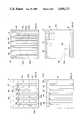
- FIG. 1is a three dimensional illustration of the external configuration of a compact high intensity cooler which embodies the invention shown in conjunction with a source of coolant,
- FIG. 2is a cross section taken along the line 2--2 in FIG. 1,
- FIG. 3is a front view of one form of an impingement orifice plate shown in section in FIG. 2,
- FIG. 4is a front view of one form of spacer plate used in the fabrication of compact high intensity cooler shown in section in FIG. 2,
- FIG. 5is a front view of yet another plate used in the fabrication of the compact high intensity cooler shown in section in FIG. 2,
- FIG. 6is a front view of still yet another plate employed in the fabrication of the compact high intensity cooler shown in section in FIG. 2,
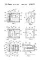
- FIG. 7is a cross-section taken along line 7--7 in FIG. 8 of a multiple impingement plate compact high intensity cooler and represents the preferred embodiment of the invention
- FIG. 8is an end view of FIG. 7,
- FIG. 9is a cross-sectional view taken along the line 9--9 in FIG. 8,
- FIG. 10is a view taken along the line A/A in FIG. 9,
- FIG. 11is an exploded view of most of the major components of the preferred embodiment of the invention shown in FIG. 7,
- FIG. 12is a three dimensional illustration of the compact high intensity cooler of FIG. 7 with its housing removed,
- FIG. 13is a cross-sectional showing of another multiple impingement plate embodiment of the invention.
- FIG. 14is a view taken along the line C/C in FIG. 13,
- FIG. 15is an impingement orifice plate with positioning tabs employed in the invention embodiment of FIG. 13,
- FIG. 16is a spacer plate with positioning tabs employed in the invention embodiment of FIG. 13,
- FIG. 17illustrates yet another embodiment of the invention wherein multiple impingement plates are shown in a compact high intensity cooler that has been sectioned to depict the cooperative relationship of the components of the cooler
- FIG. 18is a section taken along line D/D in FIG. 17,
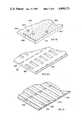
- FIG. 19is a three dimensional showing of a header plate employed in the embodiment of FIG. 17,
- FIG. 20is a three dimensional showing of an adaptor plate employed in the embodiment of FIG. 17,
- FIG. 21is a three dimensional showing of a spacer plate employed in the embodiment of FIG. 17,
- FIG. 22is a three dimensional showing of an orifice plate employed in the embodiment of FIG. 17, and
- FIG. 23is a three dimensional showing of a target plate employed in the embodiment of FIG. 17.
- FIG. 1a compact high intensity cooler 11 shown in three dimensional form in the shape of a cube.
- the CHIC 11has shown at its left hand end a heat liberating device 12, which heat liberating device 12 may be an electronic component or a heat liberating device such as the surface of a mirror.
- the CHIC 11has a housing 13 provided with an end cap 14.
- a coolant source 23is shown in dotted outline to the right of the CHIC 11 and is shown coupled to the end cap 14 via a coolant inlet tube 21 and a coolant drainage tube 24.
- FIG. 2a cross-sectional view taken along 2--2 in FIG. 1.
- the compact high intensity cooler 11is provided with a housing 13 with an end cap 14 shown brazed or soldered in place as indicated by reference numerals 16-17.
- the housing 13is typically formed of a thermally conductive material such as copper.
- the device to be cooled, 12,is shown secured to the end 15 of the housing 13.
- the surface 15may be lapped flat and the device 12 soldered thereto or held in intimate contact with thermally conductive grease.
- the reflective surface of the mirrorcould be bonded direct to the surface 15.
- an internal surface or end of the housing 20At the left hand end of the housing 13 there is designated an internal surface or end of the housing 20.
- the end of the housing on which the heat liberating device is locatedis a primary heat transmitting means.
- the internal end of the housing of the primary heat transmitting meanstakes on a different configuration as will be seen in the description of the subsequent figures of the specification.
- a stack of plates 18Between the end of the housing 20 and the cap 14 there is shown positioned a stack of plates 18 which in this embodiment take on a square shaped configuration.
- the stack of plates 18are fitted against a shoulder 19 of the housing 13.
- the stack of plates 18is held in place against the shoulder 19 by means of the cap 14 which has been, as noted above, soldered or brazed at point 16-17 to the housing 13.
- FIG. 2does not show the drainage tube 24, because the nature of the section taken, the drainage tube 24 is also brazed or soldered in place after passing through the cap 14 much in the same manner as the inlet tube 21 which has been secured to the cap 14 as described.
- the arrangement just describedprovides for a hermetically sealed housing.
- FIGS. 3, 4, 5 and 6Each of these FIGS. 3 through 6 provide the details of construction of a different type of plate used within the stack of plates 18.
- FIG. 2it will be seen that adjacent the inlet tube 21 there are shown a plate 31 and a plate 33. Separate front holes of plates 31 and 33 are not illustrated in FIGS.
- each of the transition plates 31, 33have diagonally disposed respective square drainage transition slot 32' and rectangular drainage transition slot 34'. It is believed that the cooperation of the transition slots 32, 34 is readily apparent in that coolant passing through inlet tube 21 is forced first through the square opening 32 in transition plate 31, and then through a rectangular slot 34 in plate 33.
- the next plate to the left of transition plate 33is designated a feed and return slot plate 35. This plate can be seen in FIG. 6 where feed slot 36 and return slot 37 are shown in full line.
- the next succeeding plate to the left of the feed and return slot plate 35is designated an inlet feed slot and drainage slot plate.
- the inlet feed slot and drainage slot plate 38Ais shown in FIG. 5 wherein there is depicted horizontally disposed as FIG. 5 and viewed an inlet slot 39. At right angles to the slot 39 and spaced apart therefrom are drainage slots 51, 52, 53, 54 and 55.
- Each of the plates 38A, 38B and 38Care identical in their slot configurations and when the plates are stacked together the slots therein cooperate to provide flow paths through the openings 51, 52, 53, 54 and 55.
- distribution plate 41which has a front view thereof in FIG. 4.
- the distribution plate 41is characterized by having in addition to drainage slots 51A, 52A, 53A, 54A, 55A, distribution slots 42, 43, 44, 45, 46 and 47.
- the next two plates 43 and 44are plates having the same configuration as the distribution plate 41 just described in respect of FIG. 4.
- An impingement orifice plate 61 adjacent the internal end 20 of the housing 13represents the last plate in the stack.
- the impingement orifice plate 61is shown in FIG. 3.
- the impingement orifice plate 61 as seen in FIG. 3is provided with an array of orifices of a type designated by reference numerals 62, 63 and 64.
- the impingement orifice plate 61is also provided with drainage slots 51B, 52B, 53B, 54B and 55B.
- the plates of stack 18are about 0.010 inches thick, are made of copper and are diffusion bonded one to another and to the cap 14 prior to insertion into the housing 13.
- the liquid flow paths to be described next, which flow paths are formed through the openings in the plates of stack 18,are manufactured by chemically milling slots or holes in copper sheets from which the plates are constructed prior to the plates being bonded together.
- the impingement orifices 62, 63, 64which are representative of the other unreferenced orifices in the impingement orifice plate 61 are distributed across the plate 61 to provide a uniform cooling arrangement.
- the selection of the number and size of these holes or orificesis based on an allowable pressure drop and manufacturing capability. A large number of small holes is preferable.
- Coolant under pressure from the source 23is delivered via an inlet tube 21 to and through the cap 14 as shown in FIG. 2.
- the inlet tube 21is provided with a filter screen not shown. Coolant under pressure upon emerging from the inlet tube 21 enters the square shaped opening 32 in transition plate 31, and is thereafter directed through rectangular opening 34 in transition plate 33, where it thereafter enters the top feed slot 36 of return and feed slot plate 35. Coolant emerging from top feed slot 36 enters a series of top feed slots such as 39 in inlet feed slot and drainage slot plates 38A, 38B and 38C where it is delivered to and through the distribution slots 42, 43, 44, 45, 46 and 47 of the distribution plate 41.
- the coolantpasses through the orifices in the impingement orifice plate 61 and impinge upon the internal end 20 of the housing 13 thereby removing heat conducted from the heat liberated device 12 through the end of the housing 15.
- reference numerals 66 and 67designate impingement coolant flow arrows emanating from, for example, the orifice 62.
- the coolant after impinging on the internal end 20 of the housing 13follows the path of the arrows 66, 67 and enters the drainage slots 51B and 52B, which in turn allow the coolant to pass back through the channel created by the stacked arrangement of cooperating slot openings 51A, 52A, 53A, 54A and 51, 52, 53, 54 and 55.
- the coolantis free from cross-flow with the coolant flow path described earlier with respect to the delivery of the coolant through the stack plate arrangement to the orifice impingement plate 61.
- the return coolantthen passes through the bottom distribution slot 37 of the feed and return plate 35 and commences a transition through slots 34', 42' and finally enters coolant drainage tube 24 for return to the coolant source 23.
- FIGS. 7 through 12figures illustrate in a variety of cross-sections a preferred embodiment of the invention.
- the explanation that follows the readers attentionwill be simultaneously directed to the various figures, as this will be necessary for the reader to comprehend the arrangement of the elements and their cooperation which defines the operation of the invention.
- FIG. 7shows a cross-section of a CHIC 81 which is a multiple impingement orifice plate embodiment of the invention. Details of the cooperation of the coolant and the stack of plates 87 will be readily comprehended when the description hereinafter is directed to FIG. 11.
- the CHIC 81includes a target plate end piece 82 which has been bonded to a sleeve housing 84 at target plate peripheral flange 96.
- An end cap block 86is positioned as shown within the housing 84, and is configured to present an inlet feed cavity 90 adjacent the stack of plates 87 as shown.
- the plates 87are sandwiched between the target plate end piece 82 and end cap block 86.
- the target plate end piece 82, the stack of plates 87, and the end cap block 86are diffusion bonded into a unitary structure which has placed thereover sleeve housing 84 which is then brazed as shown at point 85 to the end cap block 86 and at the peripheral flange 96 to thereby establish a hermetically sealed housing.
- the end cap block 86has a coolant inlet 106 and a drainage outlet 107, the arrangement of which can best be seen in FIG. 8.
- the end cap block 86has a stepped down portion 80 which terminates at shoulder 88.
- the stepped down portion 80, and the sleeve housing 84cooperate to form therebetween a drainage channel 89.
- the compact high intensity cooler 81has a device 83 to be cooled integrally secured to the target plate end piece 82 in the manner described hereinbefore.
- FIG. 7There can be seen in FIG. 7, the dotted outline of guide pins 101 and 102 which are seated in unreferenced openings in raised portions 92 and 93 of the target plate end piece 82 (see FIG. 10).
- the guide pins 101 and 102are utilized to secure the stack of plates 87 in an aligned arrangement during the fabrication of the CHIC 81.
- the target plate end piece 82is characterized by raised portions 91, 92, 93 and 94.
- the raised portions 91, 92, 93 and 94create therebetween target plate slots 97, 98 and 99. Attention is now directed momentarily to FIG. 12, where these target plate slots 97, 98 and 99 can be seen in the three dimensional showing of FIG. 12.
- FIG. 8is an end view of the CHIC 81, and shows the CHIC configuration to be that of a square. It is to be noted, however, that the invention contemplates that the sleeve housing 84 may take on a circular cylindrical cross-section or such other cross-section that will ease fabrication or enhance the utilization of the impingement cooling arrangement therein.
- FIG. 9In this cross-section, taken along the line 9--9 of FIG. 8, one will be able to appreciate the presence of a drainage slot 95 which cooperates with the drainage channel 89 located at the top of the CHIC 81, as well as the unreferenced drainage channel at the bottom of the compact high intensity cooler.
- FIG. 9it will be seen that the shoulder 88 of the end cap 86 presents a point beyond which coolant being returned as shown by arrow 100 cannot pass. Attention is now directed momentarily to FIG.
- coolant exiting from target plate slot 97 as evidenced by arrow 104passes along the stack of plates 87, and thence into the drainage slot 95 where it ultimately, as shown by the arrow, exits from a drainage tube 109.
- coolantis shown as evidenced by arrow 103 leaving the target plate slot 99 and entering the drainage slot 95.
- fluidalso passes along the bottom of the stack 87 and enters the drainage slot 95.
- FIG. 11is an exploded view of some of the basic components of the compact high intensity cooler absent the sleeve housing 84. In this illustration only a few plates are shown and will be described.
- FIG. 11there has been added an inlet tube 108 and a drainage tube 109 shown fitted respectively in coolant inlet 106 and drainage outlet 107.
- the device to be cooled, 83is mounted on the target plate end piece 82, which as noted before has raised portions 91, 92, 93 and 94. Adjacent to the target plate end piece 82 and bonded thereto is an impingement orifice plate 111.
- the impingement orifice plate 111has a number of orifices passing therethrough, two of which have been referenced by numerals 112 and 113. These orifices of which there are many more than two in the preferred embodiment, form a region referenced to as an impingement orifice zone.
- the impingement orifice plate 111is provided with three such impingement orifice zones, namely those designated by reference numerals 114, 116 and 117.
- impingement heat plate conduction zones 118, 119As well as two unreferenced impingement plate heat conduction zones at each end of the impingement orifice plate 111.
- a spacer plate 126Adjacent and between the impingement orifice plates 111 and 136 is a spacer plate 126 which is provided with a set of slotted openings 127, 128 and 129, which are aligned such that the orifice opens in the impingement orifice plates just noted are such that coolant may pass freely through the openings 127, 128 and 129 as coolant moves through the impingement orifice plates in a manner that will be described shortly.
- the spacer plate 126has what is termed spacer plate heat conduction zones 131 and 132, as well as two unreferenced heat conduction zones at each end of the spacer plate 126.
- the final impingement orifice plate 136 shown in FIG. 11will now be described briefly, and it will be seen to possess what is termed non-aligned orifices 137 and 138 shown in dotted outline.
- non-alignedit is intended to mean that the orifices such as 137 and 138 are not aligned with the orifices 112 and 113 of the impingement orifice plate 111.
- none of the orifices shown in dotted outline in the impingement orifice plate 136are in physical alignment with any of the openings shown in impingement orifice plate 111.
- the impingement orifice plate 136is identical to, in all other respects, the impingement orifice plate 111, in that it has impingement plate heat conduction zones 139 and 140 and is referenced heat conduction zones at each end of the plate 111.
- FIG. 11Super-imposed on the left hand portion of FIG. 11 are a set of conduction heat path arrows 141, 142, 143 and 144. If the reader envisions the arrangement shown in FIG. 11 as stacked as was described in respect of FIG. 7 through 10, then it will be readily comprehended that heat liberated from the device 83 will, for example, move along heat path 142 through target plate end piece 82, raised portion 93, thence through impingement plate conduction zone 118 where the heat as indicated by the super-imposed arrows will move outward therefrom along the impingement orifice plate 111.
- each of the impingement orifice platesrepresents a fin like structure separated by spacer plates with the entire arrangement thermally inter-connected via the aforementioned heat conduction zones.
- coolant enters inlet tube 108passes through end cap block 86 and enters the inlet feed cavity 90 and thereafter passes through, for example, the orifices 137 and 138, and thereafter passes through the opening 127 and impinges upon the surface of the impingement orifice plate 111.
- the coolantcan exit only by passing through the impingement orifices 112 and 113, where they create impingement coolant jets that strike the target plate slot 99 of the target plate end piece 82.
- the impinging fluidstrikes a heat conduction surface, it removes a portion of the heat therefrom and coolant that has accomplished its cooling function then passes through the upper and lower ends of the slots 97, 98 and 99, and into the drainage channel such as 89 (see FIG. 7) and into the drainage slot 95 and exits via drainage outlet 107 (see FIG. 12).
- the inventioncontemplates that by alternating orifice plates and spacer plates, a series of impingement heat transfer surfaces may be added together, thereby increasing the effective heat transfer area considerably. It is to be recognized that the optimum number of plates will be a function of the number and size of holes in each plate and the allowable pressure drop.
- FIG. 13illustrates in cross-section another embodiment of the invention.
- Most of the elements of the embodiment of the invention depicted in FIG. 13find their duplicate corresponding components in the just described preferred embodiment of the invention.
- the physical configuration of the various componentsare slightly modified in advantageous ways and provide alternates in the construction of the invention.
- These variations in constructionare intended to be exemplary only of the modifications that may take place in the construction of a compact high intensity cooler that embodies the invention.
- FIG. 13there is shown compact high intensity cooler 151 which has mounted on the end thereof a heat liberating device 152.
- the CHIC 151has a housing 153 configured similar to that embodiment of the invention shown in FIG. 2.
- the housing 153has what is designated a housing end 154.
- An end cap or block 150is positioned within the housing 153.
- the end cap 150is provided with an inlet feed cavity 155 which is coupled to the coolant inlet 160.
- a stack of plates 161is shown sandwiched between the end cap 150 and the internal raised portions 156, 157, 158 and 159.
- FIG. 14In order to appreciate the operation of the CHIC shown in FIG. 13, attention should be simultaneously directed to the cross-sectional showing set forth in FIG. 14. For purposes of explanation only, when FIG.
- top and bottom of the CHIC 151By the top, it is intended to mean that portion of the compact high intensity cooler 151 nearest the top of FIG. 13. With this thought in mind, it will be observed that there is present a top drainage channel 166, which is connected to and integral with a side drainage channel 167. The side drainage channel 167 can best be seen in FIG. 14.
- the CHIC 151is also provided with a bottom drainage channel 168, which is referenced in both FIGS. 13 and 14. In a manner similar to that shown and described with respect to FIGS. 7 through 12, there is provided a drainage slot 169 which cooperates with drainage outlet 162.
- coolant enters inlet 160passes through inlet feed channel 155 and then passes through the stack of plates 161 emerging at the points provided between the raised portions 156, 157, 158 and 159.
- the coolant thereafter as indicated by flow arrow 186enters the side drainage slot 167.
- FIG. 14it will be noted that there are a number of unreferenced arrows emanating from unreferenced orifice openings and these arrows are directed towards the sides of what have been described as drainage channels. Coolant fluid entering the drainage channels passes back pass the stack of plates 161 and into the drainage slot 169 and out drainage outlet 162, all without cross-flow with the coolant passing to and through the stack of plates 161.
- FIG. 14the outlines of three major components can be discerned. These components are as follows: the housing 153; a spacer plate 180, and an impingement orifice plate 185.
- the details of the spacer plateare shown in FIG. 16, where it will be noted that the spacer plate 180 is provided with openings such as opening 181 and spacer plate positioning tabs 182a, 182b, 182c, 182d, 182e and 182f.
- the spacer plate positioning tabs just notedare in alignment with impingement plate positioning tabs 190a, 190b, 190c, 190d, 190e and 190f.
- the use of positioning tabsallows the compact high intensity cooler 151 to be constructed without the use of centering pins as was the case in the preferred embodiment.
- the positioning tabsalso function to define in combination with the housing 153, drainage return channels, which drainage return channels will be appreciated as being evenly distributed around the periphery of the stack of plates 161.
- impingement orifice plate 185has in dotted outlines impingement orifice zones 187, 188 and 189. Between the impingement orifice zones just mentioned, there will be seen designated impingement plate heat conduction zones 191, 192 and 193 and 194.
- FIGS. 17 through 23provide a detailed showing of yet another embodiment of the invention.
- FIG. 17there is illustrated in partial section, a three dimensional illustration of a large module CHIC 201.
- the theory of operation of the inventionis the same in respect of the large module CHIC 201 of FIG. 17 as that which has been described in connection with the last two embodiments of the invention as set forth hereinbefore.
- FIGS. 19 through 23illustrate three dimensionally, a cooperating portion of each of the components of the component high intensity cooler 201 of FIG. 17. Identities have been given to each item or component of the CHIC 201 of FIG. 17.
- a header plate 202which can be seen in FIGS. 17 and 19.
- the header plate 202is provided with coolant inlets 203 and 204, as well as drainage outlets 205, 206.
- the header plate 202is also provided with, as can best be seen in FIG. 17, a load applying rib 207, which load applying rib 207 finds utility in the diffusion bonding construction step in the fabrication of the stack of plates shown immediately below the header plate 202.
- the coolant inlets 203 and 204are shown coupled to coolant drainage channels 208 and 209.
- An unreferenced narrow varied ridge on the side wall members 210 and 211is diffusion bonded to header plate 202 and target plate 215 when the complete assembly is bonded together during fabrication.
- a drainage channel 212cooperates with drainage outlet 205 and its detail is shown in both FIGS. 17 and 19.
- the target plate 215 just mentionedincludes a plurality of raised portions 216 and 217.
- the raised portions 216 and 217are identified in both FIGS. 17 and 23.
- FIG. 23is intended to convey the details of construction of the target plate 215.
- the target plate 215includes target plate slots 218 and 219 which cooperate with coolant fluid passing through the stack of plates from the inlet 203 as indicated by the unreferenced arrows.
- an adaptor plate 221the details of which are shown in FIG. 20 and include an adaptor plate opening 222 and a pair of adaptor plate return slots 223 and 224.
- a spacer plate 230which spacer plate 230 and the details of its construction are shown in FIG. 21 and include a pair of spacer plate openings 231, 232, a spacer plate drainage opening 233, and a spacer plate heat conduction zone 234.
- the final component in the stack of platesis that referenced to as an orifice impingement plate 240, the details of which are shown in FIG. 22 and include an impingement orifice region 241, as well as an impingement plate heat conduction zone 242, and finally an impingement plate drainage return slot 243.
- FIG. 18there is a partial section taken along the lines D/D in FIG. 17, and it will be observed that the unreferenced orifices of the stack of plates will be observed to be in non-aligned relationship with respect to coolant passing through the orifices as indicated by the arrows. The coolant impinges upon the space between the orifices on the next succeeding plate in the direction of coolant flow.
Landscapes
- Engineering & Computer Science (AREA)
- Physics & Mathematics (AREA)
- Power Engineering (AREA)
- General Physics & Mathematics (AREA)
- Computer Hardware Design (AREA)
- Microelectronics & Electronic Packaging (AREA)
- Condensed Matter Physics & Semiconductors (AREA)
- Thermal Sciences (AREA)
- Mechanical Engineering (AREA)
- General Engineering & Computer Science (AREA)
- Heat-Exchange Devices With Radiators And Conduit Assemblies (AREA)
- Turbine Rotor Nozzle Sealing (AREA)
- Cooling Or The Like Of Semiconductors Or Solid State Devices (AREA)
- Cooling Or The Like Of Electrical Apparatus (AREA)
Abstract
Description
Claims (33)
Priority Applications (4)
| Application Number | Priority Date | Filing Date | Title |
|---|---|---|---|
| US06/411,059US4494171A (en) | 1982-08-24 | 1982-08-24 | Impingement cooling apparatus for heat liberating device |
| GB08316416AGB2125951B (en) | 1982-08-24 | 1983-06-16 | Coolers for heat-liberating devices |
| JP58152613AJPS5957499A (en) | 1982-08-24 | 1983-08-23 | Compact strong cooler |
| DE19833330385DE3330385A1 (en) | 1982-08-24 | 1983-08-23 | IMPACT COOLING DEVICE |
Applications Claiming Priority (1)
| Application Number | Priority Date | Filing Date | Title |
|---|---|---|---|
| US06/411,059US4494171A (en) | 1982-08-24 | 1982-08-24 | Impingement cooling apparatus for heat liberating device |
Publications (1)
| Publication Number | Publication Date |
|---|---|
| US4494171Atrue US4494171A (en) | 1985-01-15 |
Family
ID=23627388
Family Applications (1)
| Application Number | Title | Priority Date | Filing Date |
|---|---|---|---|
| US06/411,059Expired - LifetimeUS4494171A (en) | 1982-08-24 | 1982-08-24 | Impingement cooling apparatus for heat liberating device |
Country Status (4)
| Country | Link |
|---|---|
| US (1) | US4494171A (en) |
| JP (1) | JPS5957499A (en) |
| DE (1) | DE3330385A1 (en) |
| GB (1) | GB2125951B (en) |
Cited By (114)
| Publication number | Priority date | Publication date | Assignee | Title |
|---|---|---|---|---|
| US4559580A (en)* | 1983-11-04 | 1985-12-17 | Sundstrand Corporation | Semiconductor package with internal heat exchanger |
| US4561040A (en)* | 1984-07-12 | 1985-12-24 | Ibm Corporation | Cooling system for VLSI circuit chips |
| US4628219A (en)* | 1985-09-13 | 1986-12-09 | Sundstrand Corporation | Rectifier assembly for mounting in a rotor |
| US4806814A (en)* | 1987-11-16 | 1989-02-21 | Sundstrand Corporation | Half-wave rotary rectifier assembly |
| US4827165A (en)* | 1987-11-16 | 1989-05-02 | Sundstrand Corporation | Integrated diode package |
| US4880055A (en)* | 1988-12-07 | 1989-11-14 | Sundstrand Corporation | Impingement plate type heat exchanger |
| US4901201A (en)* | 1988-10-25 | 1990-02-13 | Sundstrand Corporation | Plate fin/chic heat exchanger |
| US4910642A (en)* | 1988-12-05 | 1990-03-20 | Sundstrand Corporation | Coolant activated contact compact high intensity cooler |
| US4934454A (en)* | 1988-08-25 | 1990-06-19 | Sundstrand Corporation | Pressure sealed laminated heat exchanger |
| US4936380A (en)* | 1989-01-03 | 1990-06-26 | Sundstrand Corporation | Impingement plate type heat exchanger |
| US4962444A (en)* | 1989-01-03 | 1990-10-09 | Sunstrand Corporation | Cold chassis for cooling electronic circuit components on an electronic board |
| US4975803A (en)* | 1988-12-07 | 1990-12-04 | Sundstrand Corporation | Cold plane system for cooling electronic circuit components |
| US4993487A (en)* | 1989-03-29 | 1991-02-19 | Sundstrand Corporation | Spiral heat exchanger |
| WO1991002205A1 (en)* | 1989-07-24 | 1991-02-21 | Valenzuela Javier A | High heat flux compact heat exchanger having a permeable heat transfer element |
| US5016090A (en)* | 1990-03-21 | 1991-05-14 | International Business Machines Corporation | Cross-hatch flow distribution and applications thereof |
| US5016707A (en)* | 1989-12-28 | 1991-05-21 | Sundstrand Corporation | Multi-pass crossflow jet impingement heat exchanger |
| US5025856A (en)* | 1989-02-27 | 1991-06-25 | Sundstrand Corporation | Crossflow jet impingement heat exchanger |
| US5029640A (en)* | 1989-05-01 | 1991-07-09 | Sundstrand Corporation | Gas-liquid impingement plate type heat exchanger |
| US5038857A (en)* | 1990-06-19 | 1991-08-13 | Sundstrand Corporation | Method of diffusion bonding and laminated heat exchanger formed thereby |
| US5043797A (en)* | 1990-04-03 | 1991-08-27 | General Electric Company | Cooling header connection for a thyristor stack |
| US5056586A (en)* | 1990-06-18 | 1991-10-15 | Modine Heat Transfer, Inc. | Vortex jet impingement heat exchanger |
| US5063476A (en)* | 1989-12-05 | 1991-11-05 | Digital Equipment Corporation | Apparatus for controlled air-impingement module cooling |
| US5088005A (en)* | 1990-05-08 | 1992-02-11 | Sundstrand Corporation | Cold plate for cooling electronics |
| US5099915A (en)* | 1990-04-17 | 1992-03-31 | Sundstrand Corporation | Helical jet impingement evaporator |
| US5129449A (en)* | 1990-12-26 | 1992-07-14 | Sundstrand Corporation | High performance heat exchanger |
| US5145001A (en)* | 1989-07-24 | 1992-09-08 | Creare Inc. | High heat flux compact heat exchanger having a permeable heat transfer element |
| US5177667A (en)* | 1991-10-25 | 1993-01-05 | International Business Machines Corporation | Thermal conduction module with integral impingement cooling |
| US5196989A (en)* | 1990-04-09 | 1993-03-23 | Trw Inc. | Rigid circuit board structure using impingement cooling |
| US5239443A (en)* | 1992-04-23 | 1993-08-24 | International Business Machines Corporation | Blind hole cold plate cooling system |
| US5239200A (en)* | 1991-08-21 | 1993-08-24 | International Business Machines Corporation | Apparatus for cooling integrated circuit chips |
| US5263536A (en)* | 1991-07-19 | 1993-11-23 | Thermo Electron Technologies Corp. | Miniature heat exchanger |
| US5265670A (en)* | 1990-04-27 | 1993-11-30 | International Business Machines Corporation | Convection transfer system |
| USD341820S (en) | 1992-03-04 | 1993-11-30 | Itoh Research & Development Laboratory Co., Ltd. | Heat dissipating device for a semiconductor package |
| US5291371A (en)* | 1990-04-27 | 1994-03-01 | International Business Machines Corporation | Thermal joint |
| US5316075A (en)* | 1992-12-22 | 1994-05-31 | Hughes Aircraft Company | Liquid jet cold plate for impingement cooling |
| US5329994A (en)* | 1992-12-23 | 1994-07-19 | Sundstrand Corporation | Jet impingement heat exchanger |
| US5388635A (en)* | 1990-04-27 | 1995-02-14 | International Business Machines Corporation | Compliant fluidic coolant hat |
| US5423376A (en)* | 1993-02-12 | 1995-06-13 | Ferraz A French Societe Anonyme | Heat exchanger for electronic components and electro-technical equipment |
| US5435381A (en)* | 1990-09-14 | 1995-07-25 | Sundstrand Corporation | Shear flow/jet fin condenser |
| US5546809A (en)* | 1994-12-12 | 1996-08-20 | Houston Industries Incorporated | Vibration monitor mounting block |
| US5660227A (en)* | 1991-09-23 | 1997-08-26 | Sundstrand Corporation | Heat exchanger for high power electrical component |
| FR2748800A1 (en)* | 1996-05-15 | 1997-11-21 | Ferraz | Heat exchanger for electronic component and electric apparatus cooling |
| US5727618A (en)* | 1993-08-23 | 1998-03-17 | Sdl Inc | Modular microchannel heat exchanger |
| US5835345A (en)* | 1996-10-02 | 1998-11-10 | Sdl, Inc. | Cooler for removing heat from a heated region |
| US5864466A (en)* | 1994-07-19 | 1999-01-26 | Remsburg; Ralph | Thermosyphon-powered jet-impingement cooling device |
| WO1999004211A1 (en)* | 1997-07-17 | 1999-01-28 | Cryogen, Inc. | Cryogenic heat exchanger |
| US6014312A (en)* | 1997-03-17 | 2000-01-11 | Curamik Electronics Gmbh | Cooler or heat sink for electrical components or circuits and an electrical circuit with this heat sink |
| WO2000040068A1 (en)* | 1998-12-23 | 2000-07-06 | Hamilton Sundstrand Corporation | High intensity cooler |
| US6105661A (en)* | 1997-10-31 | 2000-08-22 | Nec Corporation | Cooling Apparatus |
| US6141219A (en)* | 1998-12-23 | 2000-10-31 | Sundstrand Corporation | Modular power electronics die having integrated cooling apparatus |
| EP0922192A4 (en)* | 1996-08-30 | 2000-11-02 | Motorola Inc | Spray-cooling an electronic component |
| US6167952B1 (en) | 1998-03-03 | 2001-01-02 | Hamilton Sundstrand Corporation | Cooling apparatus and method of assembling same |
| US20010004370A1 (en)* | 1998-08-18 | 2001-06-21 | Hamamatsu Photonics K.K. | Heat sink and semiconductor laser apparatus and semiconductor laser stack apparatus using the same |
| US20010050162A1 (en)* | 2000-06-08 | 2001-12-13 | Mikros Manufacturing, Inc. | Normal-flow heat exchanger |
| FR2818447A1 (en)* | 2000-12-18 | 2002-06-21 | Ferraz Date Ind | Cooled electrical connector incorporating piles of longitudinal laminae bundles forming a sealed chamber for the circulation of a heat carrying fluid |
| US20030037908A1 (en)* | 2001-08-07 | 2003-02-27 | Hajime Sugito | Cooling apparatus |
| US20030066634A1 (en)* | 2001-10-09 | 2003-04-10 | Mikros Manufacturing, Inc. | Heat exchanger |
| US6643302B1 (en)* | 1999-07-30 | 2003-11-04 | Fanuc Ltd. | Cooling device and surface emitting device comprising same |
| US20040112571A1 (en)* | 2002-11-01 | 2004-06-17 | Cooligy, Inc. | Method and apparatus for efficient vertical fluid delivery for cooling a heat producing device |
| US20040148959A1 (en)* | 2003-01-31 | 2004-08-05 | Cooligy, Inc. | Remedies to prevent cracking in a liquid system |
| US20040182551A1 (en)* | 2003-03-17 | 2004-09-23 | Cooligy, Inc. | Boiling temperature design in pumped microchannel cooling loops |
| US20040182548A1 (en)* | 2003-03-17 | 2004-09-23 | Cooligy, Inc. | Multi-level microchannel heat exchangers |
| US20040188066A1 (en)* | 2002-11-01 | 2004-09-30 | Cooligy, Inc. | Optimal spreader system, device and method for fluid cooled micro-scaled heat exchange |
| US20040227514A1 (en)* | 2001-02-08 | 2004-11-18 | Hernan Jara | Synthetic images for a magnetic resonance imaging scanner using linear combination of source images to generate contrast and spatial navigation |
| US20040233639A1 (en)* | 2003-01-31 | 2004-11-25 | Cooligy, Inc. | Removeable heat spreader support mechanism and method of manufacturing thereof |
| US20050210906A1 (en)* | 2004-03-26 | 2005-09-29 | Ebm-Papst St. Georgen Gmbh & Co. Kg | Heat sink |
| US20050211427A1 (en)* | 2002-11-01 | 2005-09-29 | Cooligy, Inc. | Method and apparatus for flexible fluid delivery for cooling desired hot spots in a heat producing device |
| US20050211418A1 (en)* | 2002-11-01 | 2005-09-29 | Cooligy, Inc. | Method and apparatus for efficient vertical fluid delivery for cooling a heat producing device |
| US20050211417A1 (en)* | 2002-11-01 | 2005-09-29 | Cooligy,Inc. | Interwoven manifolds for pressure drop reduction in microchannel heat exchangers |
| US20050269061A1 (en)* | 2004-06-04 | 2005-12-08 | Cooligy, Inc. | Apparatus and method of efficient fluid delivery for cooling a heat producing device |
| US20050268626A1 (en)* | 2004-06-04 | 2005-12-08 | Cooligy, Inc. | Method and apparatus for controlling freezing nucleation and propagation |
| US20060042785A1 (en)* | 2004-08-27 | 2006-03-02 | Cooligy, Inc. | Pumped fluid cooling system and method |
| US7058101B2 (en) | 2003-09-20 | 2006-06-06 | Spectra Physics, Inc. | Stepped manifold array of microchannel heat sinks |
| US7069975B1 (en) | 1999-09-16 | 2006-07-04 | Raytheon Company | Method and apparatus for cooling with a phase change material and heat pipes |
| US7075959B1 (en) | 2003-11-14 | 2006-07-11 | Hamilton Sundstrand Corporation | Cooling device for diode pumped laser |
| EP0978874A3 (en)* | 1998-08-04 | 2006-07-12 | Electrovac AG | Cooling apparatus |
| US20060175041A1 (en)* | 2005-02-09 | 2006-08-10 | Raytheon Comapny | Foil slot impingement cooler with effective light-trap cavities |
| US20060250773A1 (en)* | 2005-05-06 | 2006-11-09 | International Business Machines Corporation | Cooling apparatus, cooled electronic module and methods of fabrication thereof employing an integrated manifold and a plurality of thermally conductive fins |
| US20060260784A1 (en)* | 2005-05-19 | 2006-11-23 | International Business Machines Corporation | Microjet module assembly |
| US20070017662A1 (en)* | 2000-06-08 | 2007-01-25 | Mikros Manufacturing, Inc. | Normal-flow heat exchanger |
| US20070193642A1 (en)* | 2006-01-30 | 2007-08-23 | Douglas Werner | Tape-wrapped multilayer tubing and methods for making the same |
| US20070227708A1 (en)* | 2006-03-30 | 2007-10-04 | James Hom | Integrated liquid to air conduction module |
| US20070235167A1 (en)* | 2006-04-11 | 2007-10-11 | Cooligy, Inc. | Methodology of cooling multiple heat sources in a personal computer through the use of multiple fluid-based heat exchanging loops coupled via modular bus-type heat exchangers |
| US20070246204A1 (en)* | 2006-04-21 | 2007-10-25 | Foxconn Technology Co., Ltd. | Liquid-cooling device |
| US20070256825A1 (en)* | 2006-05-04 | 2007-11-08 | Conway Bruce R | Methodology for the liquid cooling of heat generating components mounted on a daughter card/expansion card in a personal computer through the use of a remote drive bay heat exchanger with a flexible fluid interconnect |
| US20080264604A1 (en)* | 2007-04-24 | 2008-10-30 | International Business Machines Corporation | Cooling appartaus, cooled electronic module and methods of fabrication employing a manifold structure with interleaved coolant inlet and outlet passageways |
| US20090039502A1 (en)* | 2007-08-10 | 2009-02-12 | Matsushita Electric Works, Ltd. | Heatsink and semiconductor device with heatsink |
| US20090044928A1 (en)* | 2003-01-31 | 2009-02-19 | Girish Upadhya | Method and apparatus for preventing cracking in a liquid cooling system |
| US20090080159A1 (en)* | 2005-01-14 | 2009-03-26 | Mitsubishi Denki Kabushiki Kaisha | Heat sink and cooling unit using the same |
| US20090225513A1 (en)* | 2008-03-10 | 2009-09-10 | Adrian Correa | Device and methodology for the removal of heat from an equipment rack by means of heat exchangers mounted to a door |
| US20090250195A1 (en)* | 2006-06-14 | 2009-10-08 | Toyota Jidosha Kabushiki Kaisha | Heat sink and cooler |
| US7616444B2 (en) | 2004-06-04 | 2009-11-10 | Cooligy Inc. | Gimballed attachment for multiple heat exchangers |
| US20090323285A1 (en)* | 2008-06-25 | 2009-12-31 | Sony Corporation | Heat transport device and electronic apparatus |
| US7836597B2 (en) | 2002-11-01 | 2010-11-23 | Cooligy Inc. | Method of fabricating high surface to volume ratio structures and their integration in microheat exchangers for liquid cooling system |
| WO2011115748A1 (en)* | 2010-03-16 | 2011-09-22 | Saudi Arabian Oil Company | Slotted impingement plates for heat exchangers |
| US8077460B1 (en) | 2010-07-19 | 2011-12-13 | Toyota Motor Engineering & Manufacturing North America, Inc. | Heat exchanger fluid distribution manifolds and power electronics modules incorporating the same |
| US8199505B2 (en) | 2010-09-13 | 2012-06-12 | Toyota Motor Engineering & Manufacturing Norh America, Inc. | Jet impingement heat exchanger apparatuses and power electronics modules |
| US8254422B2 (en) | 2008-08-05 | 2012-08-28 | Cooligy Inc. | Microheat exchanger for laser diode cooling |
| US20130027885A1 (en)* | 2011-07-25 | 2013-01-31 | International Business Machines Corporation | Heat spreader for multi-chip modules |
| US8391008B2 (en) | 2011-02-17 | 2013-03-05 | Toyota Motor Engineering & Manufacturing North America, Inc. | Power electronics modules and power electronics module assemblies |
| US8427832B2 (en) | 2011-01-05 | 2013-04-23 | Toyota Motor Engineering & Manufacturing North America, Inc. | Cold plate assemblies and power electronics modules |
| US8482919B2 (en) | 2011-04-11 | 2013-07-09 | Toyota Motor Engineering & Manufacturing North America, Inc. | Power electronics card assemblies, power electronics modules, and power electronics devices |
| US8659896B2 (en) | 2010-09-13 | 2014-02-25 | Toyota Motor Engineering & Manufacturing North America, Inc. | Cooling apparatuses and power electronics modules |
| US20140150992A1 (en)* | 2012-11-30 | 2014-06-05 | Raytheon Company | Threaded cooling apparatus with integrated cooling channels and heat exchanger |
| US8786078B1 (en) | 2013-01-04 | 2014-07-22 | Toyota Motor Engineering & Manufacturing North America, Inc. | Vehicles, power electronics modules and cooling apparatuses with single-phase and two-phase surface enhancement features |
| WO2015027995A1 (en)* | 2013-08-27 | 2015-03-05 | Rogers Germany Gmbh | Cooling arrangement |
| US9131631B2 (en) | 2013-08-08 | 2015-09-08 | Toyota Motor Engineering & Manufacturing North America, Inc. | Jet impingement cooling apparatuses having enhanced heat transfer assemblies |
| US9271427B2 (en) | 2012-11-28 | 2016-02-23 | Hamilton Sundstrand Corporation | Flexible thermal transfer strips |
| US9297571B1 (en) | 2008-03-10 | 2016-03-29 | Liebert Corporation | Device and methodology for the removal of heat from an equipment rack by means of heat exchangers mounted to a door |
| US20170352576A1 (en)* | 2014-10-30 | 2017-12-07 | Tokyo Electron Limited | Substrate placing table |
| CN111052360A (en)* | 2017-08-29 | 2020-04-21 | 株式会社威工 | heat sink |
| RU2727617C1 (en)* | 2019-11-01 | 2020-07-22 | Акционерное общество "Научно-производственное предприятие "Пульсар" | Radiator |
| US11047627B2 (en)* | 2016-03-31 | 2021-06-29 | Nec Corporation | Cooling device |
| RU2809232C1 (en)* | 2022-11-29 | 2023-12-08 | Акционерное общество "Научно-производственное предприятие "Пульсар" | Radiator with groups of thin fins |
Families Citing this family (1)
| Publication number | Priority date | Publication date | Assignee | Title |
|---|---|---|---|---|
| JP3122173B2 (en)* | 1990-11-09 | 2001-01-09 | 株式会社東芝 | Heatsink, heatsink, and method of manufacturing heatsink |
Citations (8)
| Publication number | Priority date | Publication date | Assignee | Title |
|---|---|---|---|---|
| DE1451246A1 (en)* | 1964-06-10 | 1969-03-27 | Maddocks Herbert F | Heat exchanger |
| US3457988A (en)* | 1967-05-15 | 1969-07-29 | Westinghouse Electric Corp | Integral heat sink for semiconductor devices |
| US3908188A (en)* | 1974-08-14 | 1975-09-23 | Us Air Force | Heat sink for microstrip circuit |
| US4093021A (en)* | 1975-12-29 | 1978-06-06 | The Boeing Company | Instrument and panel cooling apparatus |
| US4188996A (en)* | 1977-05-04 | 1980-02-19 | Ckd Praha, Oborovy Podnik | Liquid cooler for semiconductor power elements |
| US4258383A (en)* | 1978-12-22 | 1981-03-24 | Rca Corporation | Minimum pressure drop liquid cooled structure for a semiconductor device |
| US4296455A (en)* | 1979-11-23 | 1981-10-20 | International Business Machines Corporation | Slotted heat sinks for high powered air cooled modules |
| US4399484A (en)* | 1981-03-10 | 1983-08-16 | The United States Of America As Represented By The Secretary Of The Air Force | Integral electric module and assembly jet cooling system |
- 1982
- 1982-08-24USUS06/411,059patent/US4494171A/ennot_activeExpired - Lifetime
- 1983
- 1983-06-16GBGB08316416Apatent/GB2125951B/ennot_activeExpired
- 1983-08-23JPJP58152613Apatent/JPS5957499A/enactivePending
- 1983-08-23DEDE19833330385patent/DE3330385A1/ennot_activeWithdrawn
Patent Citations (8)
| Publication number | Priority date | Publication date | Assignee | Title |
|---|---|---|---|---|
| DE1451246A1 (en)* | 1964-06-10 | 1969-03-27 | Maddocks Herbert F | Heat exchanger |
| US3457988A (en)* | 1967-05-15 | 1969-07-29 | Westinghouse Electric Corp | Integral heat sink for semiconductor devices |
| US3908188A (en)* | 1974-08-14 | 1975-09-23 | Us Air Force | Heat sink for microstrip circuit |
| US4093021A (en)* | 1975-12-29 | 1978-06-06 | The Boeing Company | Instrument and panel cooling apparatus |
| US4188996A (en)* | 1977-05-04 | 1980-02-19 | Ckd Praha, Oborovy Podnik | Liquid cooler for semiconductor power elements |
| US4258383A (en)* | 1978-12-22 | 1981-03-24 | Rca Corporation | Minimum pressure drop liquid cooled structure for a semiconductor device |
| US4296455A (en)* | 1979-11-23 | 1981-10-20 | International Business Machines Corporation | Slotted heat sinks for high powered air cooled modules |
| US4399484A (en)* | 1981-03-10 | 1983-08-16 | The United States Of America As Represented By The Secretary Of The Air Force | Integral electric module and assembly jet cooling system |
Cited By (171)
| Publication number | Priority date | Publication date | Assignee | Title |
|---|---|---|---|---|
| US4559580A (en)* | 1983-11-04 | 1985-12-17 | Sundstrand Corporation | Semiconductor package with internal heat exchanger |
| US4561040A (en)* | 1984-07-12 | 1985-12-24 | Ibm Corporation | Cooling system for VLSI circuit chips |
| US4628219A (en)* | 1985-09-13 | 1986-12-09 | Sundstrand Corporation | Rectifier assembly for mounting in a rotor |
| US4806814A (en)* | 1987-11-16 | 1989-02-21 | Sundstrand Corporation | Half-wave rotary rectifier assembly |
| US4827165A (en)* | 1987-11-16 | 1989-05-02 | Sundstrand Corporation | Integrated diode package |
| US4934454A (en)* | 1988-08-25 | 1990-06-19 | Sundstrand Corporation | Pressure sealed laminated heat exchanger |
| WO1990004914A1 (en)* | 1988-10-25 | 1990-05-03 | Sundstrand Corporation | Plate fin/chic heat exchanger |
| US4901201A (en)* | 1988-10-25 | 1990-02-13 | Sundstrand Corporation | Plate fin/chic heat exchanger |
| US4910642A (en)* | 1988-12-05 | 1990-03-20 | Sundstrand Corporation | Coolant activated contact compact high intensity cooler |
| WO1990006668A1 (en)* | 1988-12-05 | 1990-06-14 | Sundstrand Corporation | Coolant activated contact compact high intensity cooler |
| US4975803A (en)* | 1988-12-07 | 1990-12-04 | Sundstrand Corporation | Cold plane system for cooling electronic circuit components |
| US4880055A (en)* | 1988-12-07 | 1989-11-14 | Sundstrand Corporation | Impingement plate type heat exchanger |
| US4936380A (en)* | 1989-01-03 | 1990-06-26 | Sundstrand Corporation | Impingement plate type heat exchanger |
| US4962444A (en)* | 1989-01-03 | 1990-10-09 | Sunstrand Corporation | Cold chassis for cooling electronic circuit components on an electronic board |
| US5025856A (en)* | 1989-02-27 | 1991-06-25 | Sundstrand Corporation | Crossflow jet impingement heat exchanger |
| US4993487A (en)* | 1989-03-29 | 1991-02-19 | Sundstrand Corporation | Spiral heat exchanger |
| US5029640A (en)* | 1989-05-01 | 1991-07-09 | Sundstrand Corporation | Gas-liquid impingement plate type heat exchanger |
| US5029638A (en)* | 1989-07-24 | 1991-07-09 | Creare Incorporated | High heat flux compact heat exchanger having a permeable heat transfer element |
| WO1991002205A1 (en)* | 1989-07-24 | 1991-02-21 | Valenzuela Javier A | High heat flux compact heat exchanger having a permeable heat transfer element |
| US5145001A (en)* | 1989-07-24 | 1992-09-08 | Creare Inc. | High heat flux compact heat exchanger having a permeable heat transfer element |
| US5063476A (en)* | 1989-12-05 | 1991-11-05 | Digital Equipment Corporation | Apparatus for controlled air-impingement module cooling |
| US5016707A (en)* | 1989-12-28 | 1991-05-21 | Sundstrand Corporation | Multi-pass crossflow jet impingement heat exchanger |
| US5016090A (en)* | 1990-03-21 | 1991-05-14 | International Business Machines Corporation | Cross-hatch flow distribution and applications thereof |
| US5043797A (en)* | 1990-04-03 | 1991-08-27 | General Electric Company | Cooling header connection for a thyristor stack |
| US5196989A (en)* | 1990-04-09 | 1993-03-23 | Trw Inc. | Rigid circuit board structure using impingement cooling |
| US5099915A (en)* | 1990-04-17 | 1992-03-31 | Sundstrand Corporation | Helical jet impingement evaporator |
| US5388635A (en)* | 1990-04-27 | 1995-02-14 | International Business Machines Corporation | Compliant fluidic coolant hat |
| US5291371A (en)* | 1990-04-27 | 1994-03-01 | International Business Machines Corporation | Thermal joint |
| US5265670A (en)* | 1990-04-27 | 1993-11-30 | International Business Machines Corporation | Convection transfer system |
| US5088005A (en)* | 1990-05-08 | 1992-02-11 | Sundstrand Corporation | Cold plate for cooling electronics |
| US5056586A (en)* | 1990-06-18 | 1991-10-15 | Modine Heat Transfer, Inc. | Vortex jet impingement heat exchanger |
| US5038857A (en)* | 1990-06-19 | 1991-08-13 | Sundstrand Corporation | Method of diffusion bonding and laminated heat exchanger formed thereby |
| US5435381A (en)* | 1990-09-14 | 1995-07-25 | Sundstrand Corporation | Shear flow/jet fin condenser |
| US5129449A (en)* | 1990-12-26 | 1992-07-14 | Sundstrand Corporation | High performance heat exchanger |
| US5263536A (en)* | 1991-07-19 | 1993-11-23 | Thermo Electron Technologies Corp. | Miniature heat exchanger |
| US5239200A (en)* | 1991-08-21 | 1993-08-24 | International Business Machines Corporation | Apparatus for cooling integrated circuit chips |
| US5749413A (en)* | 1991-09-23 | 1998-05-12 | Sundstrand Corporation | Heat exchanger for high power electrical component and package incorporating same |
| US5660227A (en)* | 1991-09-23 | 1997-08-26 | Sundstrand Corporation | Heat exchanger for high power electrical component |
| US5177667A (en)* | 1991-10-25 | 1993-01-05 | International Business Machines Corporation | Thermal conduction module with integral impingement cooling |
| USD341820S (en) | 1992-03-04 | 1993-11-30 | Itoh Research & Development Laboratory Co., Ltd. | Heat dissipating device for a semiconductor package |
| US5239443A (en)* | 1992-04-23 | 1993-08-24 | International Business Machines Corporation | Blind hole cold plate cooling system |
| US5316075A (en)* | 1992-12-22 | 1994-05-31 | Hughes Aircraft Company | Liquid jet cold plate for impingement cooling |
| US5329994A (en)* | 1992-12-23 | 1994-07-19 | Sundstrand Corporation | Jet impingement heat exchanger |
| US5423376A (en)* | 1993-02-12 | 1995-06-13 | Ferraz A French Societe Anonyme | Heat exchanger for electronic components and electro-technical equipment |
| US5727618A (en)* | 1993-08-23 | 1998-03-17 | Sdl Inc | Modular microchannel heat exchanger |
| US5864466A (en)* | 1994-07-19 | 1999-01-26 | Remsburg; Ralph | Thermosyphon-powered jet-impingement cooling device |
| US5546809A (en)* | 1994-12-12 | 1996-08-20 | Houston Industries Incorporated | Vibration monitor mounting block |
| US5901783A (en)* | 1995-10-12 | 1999-05-11 | Croyogen, Inc. | Cryogenic heat exchanger |
| US6035657A (en)* | 1995-10-12 | 2000-03-14 | Cryogen, Inc. | Flexible catheter cryosurgical system |
| FR2748800A1 (en)* | 1996-05-15 | 1997-11-21 | Ferraz | Heat exchanger for electronic component and electric apparatus cooling |
| EP0922192A4 (en)* | 1996-08-30 | 2000-11-02 | Motorola Inc | Spray-cooling an electronic component |
| US5835345A (en)* | 1996-10-02 | 1998-11-10 | Sdl, Inc. | Cooler for removing heat from a heated region |
| US6014312A (en)* | 1997-03-17 | 2000-01-11 | Curamik Electronics Gmbh | Cooler or heat sink for electrical components or circuits and an electrical circuit with this heat sink |
| WO1999004211A1 (en)* | 1997-07-17 | 1999-01-28 | Cryogen, Inc. | Cryogenic heat exchanger |
| US6105661A (en)* | 1997-10-31 | 2000-08-22 | Nec Corporation | Cooling Apparatus |
| US6167952B1 (en) | 1998-03-03 | 2001-01-02 | Hamilton Sundstrand Corporation | Cooling apparatus and method of assembling same |
| EP0978874A3 (en)* | 1998-08-04 | 2006-07-12 | Electrovac AG | Cooling apparatus |
| US20010004370A1 (en)* | 1998-08-18 | 2001-06-21 | Hamamatsu Photonics K.K. | Heat sink and semiconductor laser apparatus and semiconductor laser stack apparatus using the same |
| US6895026B2 (en)* | 1998-08-18 | 2005-05-17 | Hamamatsu Photonics K.K. | Heat sink and semiconductor laser apparatus and semiconductor laser stack apparatus using the same |
| US6152215A (en)* | 1998-12-23 | 2000-11-28 | Sundstrand Corporation | High intensity cooler |
| US6141219A (en)* | 1998-12-23 | 2000-10-31 | Sundstrand Corporation | Modular power electronics die having integrated cooling apparatus |
| WO2000040068A1 (en)* | 1998-12-23 | 2000-07-06 | Hamilton Sundstrand Corporation | High intensity cooler |
| US6643302B1 (en)* | 1999-07-30 | 2003-11-04 | Fanuc Ltd. | Cooling device and surface emitting device comprising same |
| US7416017B2 (en) | 1999-09-16 | 2008-08-26 | Raytheon Company | Method and apparatus for cooling with a phase change material and heat pipes |
| US7069975B1 (en) | 1999-09-16 | 2006-07-04 | Raytheon Company | Method and apparatus for cooling with a phase change material and heat pipes |
| US20060293086A1 (en)* | 1999-09-16 | 2006-12-28 | Raytheon Company | Method and apparatus for cooling with a phase change material and heat pipes |
| US20010050162A1 (en)* | 2000-06-08 | 2001-12-13 | Mikros Manufacturing, Inc. | Normal-flow heat exchanger |
| US7836943B2 (en) | 2000-06-08 | 2010-11-23 | Mikros Manufacturing, Inc. | Normal-flow heat exchanger |
| US20080066894A1 (en)* | 2000-06-08 | 2008-03-20 | Mikros Manufacturing, Inc. | Normal-flow heat exchanger |
| US7302998B2 (en) | 2000-06-08 | 2007-12-04 | Mikros Manufacturing, Inc. | Normal-flow heat exchanger |
| US20070017662A1 (en)* | 2000-06-08 | 2007-01-25 | Mikros Manufacturing, Inc. | Normal-flow heat exchanger |
| US6935411B2 (en) | 2000-06-08 | 2005-08-30 | Mikros Manufacturing, Inc. | Normal-flow heat exchanger |
| FR2818447A1 (en)* | 2000-12-18 | 2002-06-21 | Ferraz Date Ind | Cooled electrical connector incorporating piles of longitudinal laminae bundles forming a sealed chamber for the circulation of a heat carrying fluid |
| US20040227514A1 (en)* | 2001-02-08 | 2004-11-18 | Hernan Jara | Synthetic images for a magnetic resonance imaging scanner using linear combination of source images to generate contrast and spatial navigation |
| US20050051302A1 (en)* | 2001-08-07 | 2005-03-10 | Hajime Sugito | Cooling apparatus |
| US6742574B2 (en)* | 2001-08-07 | 2004-06-01 | Denso Corporation | Cooling apparatus |
| US20030037908A1 (en)* | 2001-08-07 | 2003-02-27 | Hajime Sugito | Cooling apparatus |
| US7278474B2 (en) | 2001-10-09 | 2007-10-09 | Mikros Manufacturing, Inc. | Heat exchanger |
| US20030066634A1 (en)* | 2001-10-09 | 2003-04-10 | Mikros Manufacturing, Inc. | Heat exchanger |
| US20050211417A1 (en)* | 2002-11-01 | 2005-09-29 | Cooligy,Inc. | Interwoven manifolds for pressure drop reduction in microchannel heat exchangers |
| US20040112571A1 (en)* | 2002-11-01 | 2004-06-17 | Cooligy, Inc. | Method and apparatus for efficient vertical fluid delivery for cooling a heat producing device |
| US7806168B2 (en) | 2002-11-01 | 2010-10-05 | Cooligy Inc | Optimal spreader system, device and method for fluid cooled micro-scaled heat exchange |
| US20050211427A1 (en)* | 2002-11-01 | 2005-09-29 | Cooligy, Inc. | Method and apparatus for flexible fluid delivery for cooling desired hot spots in a heat producing device |
| US20050211418A1 (en)* | 2002-11-01 | 2005-09-29 | Cooligy, Inc. | Method and apparatus for efficient vertical fluid delivery for cooling a heat producing device |
| US20040188066A1 (en)* | 2002-11-01 | 2004-09-30 | Cooligy, Inc. | Optimal spreader system, device and method for fluid cooled micro-scaled heat exchange |
| US7836597B2 (en) | 2002-11-01 | 2010-11-23 | Cooligy Inc. | Method of fabricating high surface to volume ratio structures and their integration in microheat exchangers for liquid cooling system |
| US20050183845A1 (en)* | 2003-01-31 | 2005-08-25 | Mark Munch | Remedies to prevent cracking in a liquid system |
| US7344363B2 (en) | 2003-01-31 | 2008-03-18 | Cooligy Inc. | Remedies to prevent cracking in a liquid system |
| US20090044928A1 (en)* | 2003-01-31 | 2009-02-19 | Girish Upadhya | Method and apparatus for preventing cracking in a liquid cooling system |
| US7201214B2 (en) | 2003-01-31 | 2007-04-10 | Cooligy, Inc. | Remedies to prevent cracking in a liquid system |
| US20050183444A1 (en)* | 2003-01-31 | 2005-08-25 | Mark Munch | Remedies to prevent cracking in a liquid system |
| US20040148959A1 (en)* | 2003-01-31 | 2004-08-05 | Cooligy, Inc. | Remedies to prevent cracking in a liquid system |
| US20050183445A1 (en)* | 2003-01-31 | 2005-08-25 | Mark Munch | Remedies to prevent cracking in a liquid system |
| US7402029B2 (en) | 2003-01-31 | 2008-07-22 | Cooligy Inc. | Remedies to prevent cracking in a liquid system |
| US7201012B2 (en) | 2003-01-31 | 2007-04-10 | Cooligy, Inc. | Remedies to prevent cracking in a liquid system |
| US20050210913A1 (en)* | 2003-01-31 | 2005-09-29 | Mark Munch | Remedies to prevent cracking in a liquid system |
| US7278549B2 (en) | 2003-01-31 | 2007-10-09 | Cooligy Inc. | Remedies to prevent cracking in a liquid system |
| US20050183443A1 (en)* | 2003-01-31 | 2005-08-25 | Mark Munch | Remedies to prevent cracking in a liquid system |
| US20040233639A1 (en)* | 2003-01-31 | 2004-11-25 | Cooligy, Inc. | Removeable heat spreader support mechanism and method of manufacturing thereof |
| US7156159B2 (en) | 2003-03-17 | 2007-01-02 | Cooligy, Inc. | Multi-level microchannel heat exchangers |
| US20040182548A1 (en)* | 2003-03-17 | 2004-09-23 | Cooligy, Inc. | Multi-level microchannel heat exchangers |
| US20040182551A1 (en)* | 2003-03-17 | 2004-09-23 | Cooligy, Inc. | Boiling temperature design in pumped microchannel cooling loops |
| US7058101B2 (en) | 2003-09-20 | 2006-06-06 | Spectra Physics, Inc. | Stepped manifold array of microchannel heat sinks |
| US7075959B1 (en) | 2003-11-14 | 2006-07-11 | Hamilton Sundstrand Corporation | Cooling device for diode pumped laser |
| WO2005093830A1 (en)* | 2004-03-26 | 2005-10-06 | Ebm-Papst St. Georgen Gmbh & Co. Kg | Heat exchanger |
| US20050210906A1 (en)* | 2004-03-26 | 2005-09-29 | Ebm-Papst St. Georgen Gmbh & Co. Kg | Heat sink |
| US7616444B2 (en) | 2004-06-04 | 2009-11-10 | Cooligy Inc. | Gimballed attachment for multiple heat exchangers |
| US7188662B2 (en)* | 2004-06-04 | 2007-03-13 | Cooligy, Inc. | Apparatus and method of efficient fluid delivery for cooling a heat producing device |
| US20050268626A1 (en)* | 2004-06-04 | 2005-12-08 | Cooligy, Inc. | Method and apparatus for controlling freezing nucleation and propagation |
| US7293423B2 (en) | 2004-06-04 | 2007-11-13 | Cooligy Inc. | Method and apparatus for controlling freezing nucleation and propagation |
| US20050269061A1 (en)* | 2004-06-04 | 2005-12-08 | Cooligy, Inc. | Apparatus and method of efficient fluid delivery for cooling a heat producing device |
| US20060042785A1 (en)* | 2004-08-27 | 2006-03-02 | Cooligy, Inc. | Pumped fluid cooling system and method |
| EP1837909A4 (en)* | 2005-01-14 | 2011-03-02 | Mitsubishi Electric Corp | COOLING BODY AND COOLING UNIT THEREWITH |
| US8225854B2 (en) | 2005-01-14 | 2012-07-24 | Mitsubishi Denki Kabushiki Kaisha | Heat sink and cooling unit using the same |
| US20090080159A1 (en)* | 2005-01-14 | 2009-03-26 | Mitsubishi Denki Kabushiki Kaisha | Heat sink and cooling unit using the same |
| WO2006086297A1 (en)* | 2005-02-09 | 2006-08-17 | Raytheon Company | Foil slot impingement cooler with effective light-trap cavities |
| US20060175041A1 (en)* | 2005-02-09 | 2006-08-10 | Raytheon Comapny | Foil slot impingement cooler with effective light-trap cavities |
| US7472741B2 (en)* | 2005-02-09 | 2009-01-06 | Raytheon Company | Foil slot impingement cooler with effective light-trap cavities |
| US20060250773A1 (en)* | 2005-05-06 | 2006-11-09 | International Business Machines Corporation | Cooling apparatus, cooled electronic module and methods of fabrication thereof employing an integrated manifold and a plurality of thermally conductive fins |
| US7233494B2 (en)* | 2005-05-06 | 2007-06-19 | International Business Machines Corporation | Cooling apparatus, cooled electronic module and methods of fabrication thereof employing an integrated manifold and a plurality of thermally conductive fins |
| US7992627B2 (en) | 2005-05-19 | 2011-08-09 | International Business Machines Corporation | Microjet module assembly |
| US20060260784A1 (en)* | 2005-05-19 | 2006-11-23 | International Business Machines Corporation | Microjet module assembly |
| US7516776B2 (en)* | 2005-05-19 | 2009-04-14 | International Business Machines Corporation | Microjet module assembly |
| US20090095444A1 (en)* | 2005-05-19 | 2009-04-16 | International Business Machines Corporation | Microjet module assembly |
| US7913719B2 (en)* | 2006-01-30 | 2011-03-29 | Cooligy Inc. | Tape-wrapped multilayer tubing and methods for making the same |
| US20070193642A1 (en)* | 2006-01-30 | 2007-08-23 | Douglas Werner | Tape-wrapped multilayer tubing and methods for making the same |
| US8157001B2 (en) | 2006-03-30 | 2012-04-17 | Cooligy Inc. | Integrated liquid to air conduction module |
| US20070227708A1 (en)* | 2006-03-30 | 2007-10-04 | James Hom | Integrated liquid to air conduction module |
| US7715194B2 (en) | 2006-04-11 | 2010-05-11 | Cooligy Inc. | Methodology of cooling multiple heat sources in a personal computer through the use of multiple fluid-based heat exchanging loops coupled via modular bus-type heat exchangers |
| US20070235167A1 (en)* | 2006-04-11 | 2007-10-11 | Cooligy, Inc. | Methodology of cooling multiple heat sources in a personal computer through the use of multiple fluid-based heat exchanging loops coupled via modular bus-type heat exchangers |
| US7584781B2 (en)* | 2006-04-21 | 2009-09-08 | Fu Zhun Precision Industry (Shen Zhen) Co., Ltd. | Liquid-cooling device |
| US20070246204A1 (en)* | 2006-04-21 | 2007-10-25 | Foxconn Technology Co., Ltd. | Liquid-cooling device |
| US20070256825A1 (en)* | 2006-05-04 | 2007-11-08 | Conway Bruce R | Methodology for the liquid cooling of heat generating components mounted on a daughter card/expansion card in a personal computer through the use of a remote drive bay heat exchanger with a flexible fluid interconnect |
| US20090250195A1 (en)* | 2006-06-14 | 2009-10-08 | Toyota Jidosha Kabushiki Kaisha | Heat sink and cooler |
| US20080264604A1 (en)* | 2007-04-24 | 2008-10-30 | International Business Machines Corporation | Cooling appartaus, cooled electronic module and methods of fabrication employing a manifold structure with interleaved coolant inlet and outlet passageways |
| US7762314B2 (en)* | 2007-04-24 | 2010-07-27 | International Business Machines Corporation | Cooling apparatus, cooled electronic module and methods of fabrication employing a manifold structure with interleaved coolant inlet and outlet passageways |
| US8242595B2 (en)* | 2007-08-10 | 2012-08-14 | Panasonic Electric Works SUNX Co., Ltd. | Heatsink and semiconductor device with heatsink |
| US20090039502A1 (en)* | 2007-08-10 | 2009-02-12 | Matsushita Electric Works, Ltd. | Heatsink and semiconductor device with heatsink |
| US8250877B2 (en) | 2008-03-10 | 2012-08-28 | Cooligy Inc. | Device and methodology for the removal of heat from an equipment rack by means of heat exchangers mounted to a door |
| US20090225513A1 (en)* | 2008-03-10 | 2009-09-10 | Adrian Correa | Device and methodology for the removal of heat from an equipment rack by means of heat exchangers mounted to a door |
| US20090225514A1 (en)* | 2008-03-10 | 2009-09-10 | Adrian Correa | Device and methodology for the removal of heat from an equipment rack by means of heat exchangers mounted to a door |
| US20090225515A1 (en)* | 2008-03-10 | 2009-09-10 | James Hom | Thermal bus or junction for the removal of heat from electronic components |
| US9297571B1 (en) | 2008-03-10 | 2016-03-29 | Liebert Corporation | Device and methodology for the removal of heat from an equipment rack by means of heat exchangers mounted to a door |
| US20090323285A1 (en)* | 2008-06-25 | 2009-12-31 | Sony Corporation | Heat transport device and electronic apparatus |
| US8254422B2 (en) | 2008-08-05 | 2012-08-28 | Cooligy Inc. | Microheat exchanger for laser diode cooling |
| US8299604B2 (en) | 2008-08-05 | 2012-10-30 | Cooligy Inc. | Bonded metal and ceramic plates for thermal management of optical and electronic devices |
| WO2011115748A1 (en)* | 2010-03-16 | 2011-09-22 | Saudi Arabian Oil Company | Slotted impingement plates for heat exchangers |
| US20110226455A1 (en)* | 2010-03-16 | 2011-09-22 | Saudi Arabian Oil Company | Slotted impingement plates for heat exchangers |
| US8077460B1 (en) | 2010-07-19 | 2011-12-13 | Toyota Motor Engineering & Manufacturing North America, Inc. | Heat exchanger fluid distribution manifolds and power electronics modules incorporating the same |
| US8199505B2 (en) | 2010-09-13 | 2012-06-12 | Toyota Motor Engineering & Manufacturing Norh America, Inc. | Jet impingement heat exchanger apparatuses and power electronics modules |
| US8659896B2 (en) | 2010-09-13 | 2014-02-25 | Toyota Motor Engineering & Manufacturing North America, Inc. | Cooling apparatuses and power electronics modules |
| US8427832B2 (en) | 2011-01-05 | 2013-04-23 | Toyota Motor Engineering & Manufacturing North America, Inc. | Cold plate assemblies and power electronics modules |
| US8391008B2 (en) | 2011-02-17 | 2013-03-05 | Toyota Motor Engineering & Manufacturing North America, Inc. | Power electronics modules and power electronics module assemblies |
| US8482919B2 (en) | 2011-04-11 | 2013-07-09 | Toyota Motor Engineering & Manufacturing North America, Inc. | Power electronics card assemblies, power electronics modules, and power electronics devices |
| US20130027885A1 (en)* | 2011-07-25 | 2013-01-31 | International Business Machines Corporation | Heat spreader for multi-chip modules |
| US9271427B2 (en) | 2012-11-28 | 2016-02-23 | Hamilton Sundstrand Corporation | Flexible thermal transfer strips |
| US11231239B2 (en) | 2012-11-30 | 2022-01-25 | Raytheon Company | Threaded cooling apparatus with integrated cooling channels and heat exchanger |
| US20140150992A1 (en)* | 2012-11-30 | 2014-06-05 | Raytheon Company | Threaded cooling apparatus with integrated cooling channels and heat exchanger |
| US8786078B1 (en) | 2013-01-04 | 2014-07-22 | Toyota Motor Engineering & Manufacturing North America, Inc. | Vehicles, power electronics modules and cooling apparatuses with single-phase and two-phase surface enhancement features |
| US9131631B2 (en) | 2013-08-08 | 2015-09-08 | Toyota Motor Engineering & Manufacturing North America, Inc. | Jet impingement cooling apparatuses having enhanced heat transfer assemblies |
| WO2015027995A1 (en)* | 2013-08-27 | 2015-03-05 | Rogers Germany Gmbh | Cooling arrangement |
| US20170352576A1 (en)* | 2014-10-30 | 2017-12-07 | Tokyo Electron Limited | Substrate placing table |
| US11171033B2 (en) | 2014-10-30 | 2021-11-09 | Tokyo Electron Limited | Substrate placing table |
| US10283398B2 (en)* | 2014-10-30 | 2019-05-07 | Tokyo Electron Limited | Substrate placing table |
| US11047627B2 (en)* | 2016-03-31 | 2021-06-29 | Nec Corporation | Cooling device |
| CN111052360A (en)* | 2017-08-29 | 2020-04-21 | 株式会社威工 | heat sink |
| CN111052360B (en)* | 2017-08-29 | 2023-08-04 | 株式会社威尔康 | heat sink |
| US11948860B2 (en) | 2017-08-29 | 2024-04-02 | Welcon Inc. | Heat sink |
| US12211768B2 (en) | 2017-08-29 | 2025-01-28 | Welcon Inc. | Heat sink |
| RU2727617C1 (en)* | 2019-11-01 | 2020-07-22 | Акционерное общество "Научно-производственное предприятие "Пульсар" | Radiator |
| RU2809232C1 (en)* | 2022-11-29 | 2023-12-08 | Акционерное общество "Научно-производственное предприятие "Пульсар" | Radiator with groups of thin fins |
Also Published As
| Publication number | Publication date |
|---|---|
| GB2125951B (en) | 1985-09-18 |
| GB8316416D0 (en) | 1983-07-20 |
| GB2125951A (en) | 1984-03-14 |
| DE3330385A1 (en) | 1984-03-01 |
| JPS5957499A (en) | 1984-04-03 |
Similar Documents
| Publication | Publication Date | Title |
|---|---|---|
| US4494171A (en) | Impingement cooling apparatus for heat liberating device | |
| US5088005A (en) | Cold plate for cooling electronics | |
| US5125451A (en) | Heat exchanger for solid-state electronic devices | |
| US5232047A (en) | Heat exchanger for solid-state electronic devices | |
| US5263251A (en) | Method of fabricating a heat exchanger for solid-state electronic devices | |
| US6431260B1 (en) | Cavity plate and jet nozzle assemblies for use in cooling an electronic module, and methods of fabrication thereof | |
| JPH02228096A (en) | Cold chasse for electronic circuit board | |
| US7233494B2 (en) | Cooling apparatus, cooled electronic module and methods of fabrication thereof employing an integrated manifold and a plurality of thermally conductive fins | |
| US5412536A (en) | Local condensation control for liquid impingement two-phase cooling | |
| US6167952B1 (en) | Cooling apparatus and method of assembling same | |
| US6305463B1 (en) | Air or liquid cooled computer module cold plate | |
| US7017655B2 (en) | Forced fluid heat sink | |
| US5177667A (en) | Thermal conduction module with integral impingement cooling | |
| US4561040A (en) | Cooling system for VLSI circuit chips | |
| US5016090A (en) | Cross-hatch flow distribution and applications thereof | |
| US6557354B1 (en) | Thermoelectric-enhanced heat exchanger | |
| US4975803A (en) | Cold plane system for cooling electronic circuit components | |
| JP3203475B2 (en) | Semiconductor device | |
| WO1983003945A1 (en) | Heat pipe cooling module for high power circuit boards | |
| US4442475A (en) | Tapered seal for flow-through module | |
| US5745514A (en) | Laser diode structure with integrated heat sink | |
| KR100429840B1 (en) | Micro-cooling device | |
| JPH0738025A (en) | Cooling structure | |
| JP2728105B2 (en) | Cooling device for integrated circuits | |
| KR102539336B1 (en) | Semiconductor device thermal management module and manufacturing method thereof |
Legal Events
| Date | Code | Title | Description |
|---|---|---|---|
| AS | Assignment | Owner name:SUNDSTRAND CORPORATION Free format text:ASSIGNMENT OF ASSIGNORS INTEREST.;ASSIGNORS:BLAND, TIMOTHY J.;NIGGEMANN, RICHARD E.;REEL/FRAME:004063/0086 Effective date:19820820 Owner name:SUNDSTRAND CORPORATION, STATELESS Free format text:ASSIGNMENT OF ASSIGNORS INTEREST;ASSIGNORS:BLAND, TIMOTHY J.;NIGGEMANN, RICHARD E.;REEL/FRAME:004063/0086 Effective date:19820820 | |
| STCF | Information on status: patent grant | Free format text:PATENTED CASE | |
| FEPP | Fee payment procedure | Free format text:PAYOR NUMBER ASSIGNED (ORIGINAL EVENT CODE: ASPN); ENTITY STATUS OF PATENT OWNER: LARGE ENTITY | |
| FPAY | Fee payment | Year of fee payment:4 | |
| FPAY | Fee payment | Year of fee payment:8 | |
| REMI | Maintenance fee reminder mailed | ||
| FPAY | Fee payment | Year of fee payment:12 | |
| SULP | Surcharge for late payment | ||
| FEPP | Fee payment procedure | Free format text:PAYOR NUMBER ASSIGNED (ORIGINAL EVENT CODE: ASPN); ENTITY STATUS OF PATENT OWNER: LARGE ENTITY Free format text:PAYER NUMBER DE-ASSIGNED (ORIGINAL EVENT CODE: RMPN); ENTITY STATUS OF PATENT OWNER: LARGE ENTITY |