US4493710A - Intravenous drip rate control device - Google Patents
Intravenous drip rate control deviceDownload PDFInfo
- Publication number
- US4493710A US4493710AUS06/550,803US55080383AUS4493710AUS 4493710 AUS4493710 AUS 4493710AUS 55080383 AUS55080383 AUS 55080383AUS 4493710 AUS4493710 AUS 4493710A
- Authority
- US
- United States
- Prior art keywords
- drip
- valve member
- tube
- rate
- intravenous
- Prior art date
- Legal status (The legal status is an assumption and is not a legal conclusion. Google has not performed a legal analysis and makes no representation as to the accuracy of the status listed.)
- Expired - Fee Related
Links
- 238000001990intravenous administrationMethods0.000titleclaimsabstractdescription24
- 230000004044responseEffects0.000claimsabstractdescription4
- 239000012530fluidSubstances0.000claimsdescription9
- 230000007423decreaseEffects0.000claimsdescription5
- 230000002441reversible effectEffects0.000claims1
- 239000003978infusion fluidSubstances0.000description8
- 230000005484gravityEffects0.000description7
- 230000009471actionEffects0.000description5
- 230000003247decreasing effectEffects0.000description4
- 230000006835compressionEffects0.000description3
- 238000007906compressionMethods0.000description3
- 230000002035prolonged effectEffects0.000description3
- 210000003462veinAnatomy0.000description3
- 230000000007visual effectEffects0.000description3
- 239000004020conductorSubstances0.000description2
- 238000010276constructionMethods0.000description2
- 238000010586diagramMethods0.000description2
- 230000006870functionEffects0.000description2
- 238000001802infusionMethods0.000description2
- 239000004973liquid crystal related substanceSubstances0.000description2
- 239000000463materialSubstances0.000description2
- 230000000737periodic effectEffects0.000description2
- 230000008859changeEffects0.000description1
- 230000000994depressogenic effectEffects0.000description1
- 238000001514detection methodMethods0.000description1
- 230000000694effectsEffects0.000description1
- 239000003292glueSubstances0.000description1
- 230000007246mechanismEffects0.000description1
- 238000000034methodMethods0.000description1
- 230000004048modificationEffects0.000description1
- 238000012986modificationMethods0.000description1
- 230000000474nursing effectEffects0.000description1
- 229920003023plasticPolymers0.000description1
- 239000000243solutionSubstances0.000description1
- 230000001960triggered effectEffects0.000description1
- 125000000391vinyl groupChemical group[H]C([*])=C([H])[H]0.000description1
- 229920002554vinyl polymerPolymers0.000description1
Images


Classifications
- A—HUMAN NECESSITIES
- A61—MEDICAL OR VETERINARY SCIENCE; HYGIENE
- A61M—DEVICES FOR INTRODUCING MEDIA INTO, OR ONTO, THE BODY; DEVICES FOR TRANSDUCING BODY MEDIA OR FOR TAKING MEDIA FROM THE BODY; DEVICES FOR PRODUCING OR ENDING SLEEP OR STUPOR
- A61M5/00—Devices for bringing media into the body in a subcutaneous, intra-vascular or intramuscular way; Accessories therefor, e.g. filling or cleaning devices, arm-rests
- A61M5/14—Infusion devices, e.g. infusing by gravity; Blood infusion; Accessories therefor
- A61M5/168—Means for controlling media flow to the body or for metering media to the body, e.g. drip meters, counters ; Monitoring media flow to the body
- A61M5/16886—Means for controlling media flow to the body or for metering media to the body, e.g. drip meters, counters ; Monitoring media flow to the body for measuring fluid flow rate, i.e. flowmeters
- A61M5/1689—Drip counters
- Y—GENERAL TAGGING OF NEW TECHNOLOGICAL DEVELOPMENTS; GENERAL TAGGING OF CROSS-SECTIONAL TECHNOLOGIES SPANNING OVER SEVERAL SECTIONS OF THE IPC; TECHNICAL SUBJECTS COVERED BY FORMER USPC CROSS-REFERENCE ART COLLECTIONS [XRACs] AND DIGESTS
- Y10—TECHNICAL SUBJECTS COVERED BY FORMER USPC
- Y10S—TECHNICAL SUBJECTS COVERED BY FORMER USPC CROSS-REFERENCE ART COLLECTIONS [XRACs] AND DIGESTS
- Y10S128/00—Surgery
- Y10S128/13—Infusion monitoring
Definitions
- This inventionrelates to intravenous feed devices, and more particularly to a controller device for controlling the drip rate of intravenous fluid from a gravity feed container.
- the drip tubeis mechanically compressed to reduce the rate of flow of the intravenous fluid and the compression applied to the drip tube is decreased to increase the drip rate.
- a solenoid plungeris typically used in certain of the prior art devices for compressing the drip tube when the drip rate is to be decreased.
- drip tubesare usually formed of plasticized vinyl and these tubes experience cold flow when distorted by compression so that the compressed area of the tube remains in a kinked or pinched condition. Readjustment of such prior art devices requires repositioning of the drip tube by an attendant to permit the solenoid plunger to engage an unkinked portion of the tube.
- Prior art devices utilizing compression to throttle the drip rate of intravenous fluidare only marginally accurate and do require the periodic presence of an attendant as a result of the distortion of the drip tubes. For example, the state of the art devices are not reliable for prolonged low drip rates of about 3-5 drops per minute. Further, the prior art devices are also incapable of accurate, precise high drip rates of approximately 69 drops per minute.
- a more specific object of this inventionis to provide a novel control device which controls the drip rate of the I.V. fluid by gripping and alternately tensioning or untensioning the drip tube to accurately throttle or open the drip tube to conform to a present drip rate.
- Another object of this inventionis to provide a novel control device which accurately throttles or opens the drip tube to control the drip rate of the I.V. fluid, but which eliminates inadvertent closure resulting from "cold flow" of the material forming the drip tube.
- a further object of this inventionis to provide a control device which is operable for selectively throttling or opening the drip tube to permit prolonged low drip rates of about 3-5 drops per minute or, alternatively, prolonged high drip rates of up to approximately 200 drops per minute.
- Another object of this inventionis to provide a control device for a gravity feed container which continuously and automatically senses and adjusts the drip rate of the fluid to a preset rate, and thereby obviates the need of an attendant to check and make such adjustments.
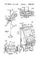
- FIG. 1is a perspective view of the novel drip rate control device mounted on a stand in flow-controlling relation with respect to the drip tube of a gravity feed container;
- FIG. 2is a fragmentary enlarged diagrammatic view of the photoelectric cell sensing mechanism taken approximately along line 2--2 of FIG. 1;
- FIG. 3is a front perspective view of the control device
- FIG. 4is a cross-sectional view taken approximately along line 4--4 of FIG. 3 and looking in the direction of the arrows;
- FIG. 5is a cross-sectional view taken approximately along line 5--5 of FIG. 4 and looking in the direction of the arrows;
- FIG. 6is a cross-sectional view similar to FIG. 5 but illustrating the clamping jaws of the control device in an open position
- FIG. 7is a cross-sectional view taken approximately along line 7--7 of FIG. 5 and looking in the direction of the arrows;
- FIG. 8is a cross-sectional view taken approximately along line 8--8 of FIG. 4 and looking in the direction of the arrows;
- FIG. 9is a plan view of a modified form of the clamping jaws.
- FIG. 10is a block diagram of the electrical circuitry of the apparatus.
- the controller device 10is illustrated as being mounted on an intravenous stand 11, intermediate the ends of the latter.
- the I.V. stand 11is provided with a transverse bracket 12 at its upper end which supports an I.V. gravity feed container 13.
- the I.V. container 13is adapted to contain a predetermined amount of intravenous fluid, which is discharged therefrom by action of gravity through a feed tube 14 that projects downwardly from the container.
- the feed tube 14is connected in communicating relation with a drip chamber 15 to which is connected the upper end of an elongate drip tube 16.
- the drip tube 16infuses the fluid into a patient by an intravenous needle in a well-known manner.
- a photoelectric cell reader (drop sensor) 17is mounted on the drip chamber 15 and includes a light emitting diode (LED) 18 and an on-axis and two off-axis photo transistors 19.
- An electrical conductor cable 20interconnects the photoelectric cell reader 17 with the controller device 10.
- the construction and operation of the photoelectric cell reader drop sensor 17is substantially identical to that disclosed in U.S. Pat. No. 4,383,252, and the disclosure thereof is incorporated herein by reference thereto.
- the drip rate controller device 10includes a housing 21 which is comprised of an inclined disposed front wall 22, a downwardly vertical declined rear wall 23, substantially parallel opposed vertical side walls 24, a top wall 25 and a lower wall 26. It will be seen that the lower wall 26 has a large opening 27 therein. It will also be seen that the bottom wall 26 has an upwardly projecting clamping element 26a integral therewith adjacent the front marginal portion thereof. The purpose of the clamping element 26a will be made more fully known herein below.
- the front wall 22 of the housinghas a control panel or key pad 28 mounted thereon which includes a plurality of touch sensitive switches 29 and which also includes a visual liquid crystal (LCD) display 30.
- the touch sensitive switches 29are components of the microprocessor circuitry incorporated in the drip rate controller device 10.
- the housing 21has a horizontally disposed, elongate bracket 31 extending between and secured to the front and rear walls thereof, adjacent but spaced above the bottom wall thereof.
- the bracket 31has an opening 32 therethrough adjacent the forward end thereof, and an opening 33 located adjacent the rear end thereof.
- the front wall of the housing 21has a pair of vertically disposed, laterally spaced apart, substantially parallel guide elements 34 rigidly affixed to the rear surface thereof by suitable securing means such as bolts and the like.
- Each guide element 34has a flange 35 integral therewith and projecting inwardly therefrom.
- a generally U-shaped bracket 36comprised of a web 37 and opposed, substantially parallel flanges 38 is rigidly secured to the guide elements 34 by bolts, as best seen in FIGS. 4 and 8.
- Meansare provided for controlling the flow of fluid to the patient, and this means includes a valve comprised of an upper jaw 39 and a lower jaw 40.
- the upper jaw 39includes a generally rectangular shaped body 41 having vertical side edge portions thereof that are engaged in the guide elements 34.
- the upper jaw body 41is provided with a centrally located opening therein, and also includes a reduced lower portion that defines a jaw element 43.
- the jaw element 43is provided with a plurality of alternate projections 44 and recesses 45. Each projection 44 and each recess 45 is smoothly curved so that the projections and recesses present a convoluted surface.
- the upper jaw 39is vertically shiftable along the guide elements 34 and means are provided for yieldably resisting downward shifting movement of the upper jaw.
- the upper end portions of the upper jaw body 41are provided with outwardly projecting extensions 47, each having a downwardly extending positioning stud 48 depending therefrom.
- a pair of helical return springs 49each engage one of the lateral extensions 47 and a positioning stud 48 thereon.
- the lower end portion of each helical springalso engages a positioning stud 50 on a lateral extension 51 integral with and projecting outwardly of each guide element 34 intermediate the ends thereof. It will therefore be seen that downward shifting movement of the upper jaw is yieldably resisted by the helical springs 49.
- Meansare provided for shiftng the upper jaw in a downward direction against the bias of the helical springs 49, and this means includes a stepping motor 52 which is positioned within the housing 21 and is mounted on the web 37 of the bracket 36.
- the stepping motor 52has an output shaft 53 which projects therefrom, and the outer end portion of the output shaft is reduced and projects into a bearing recess 54 formed on the inner surface of the front wall 22.
- a rotary cam 55is keyed to the output shaft 53 of the stepping motor 52 for rotation therewith.
- the rotary camhas a rotary cam surface 55a which engages a cam follower roller 56 positioned between and journaled on a pair of mounting strips 57.
- the mounting strips 57are positioned on opposite sides of the upper jaw body 41 and are secured thereto by any suitable securing means, such as glue or the like.
- the rolleris positioned in the lower reduced portion of the opening 42.
- the return springs 49urge the small cam follower roller 56 into engaging relation with the cam 55. It will be seen that when the stepping motor is energized to rotate the cam 55 in a counter-clockwise direction, as viewed in FIG. 4, the upper jaw will be shifted downwardly. Conversely, when the stepping motor is energized to rotate the cam 55 in a clockwise direction, the follower-type roller 56 will follow the cam surface and will be shifted upwardly by the action of the helical springs 49.
- the lower jaw 40includes a generally rectangularly shaped body 58 which is positioned in the housing 21 and extends in a fore and aft direction.
- the rear end portion of the lower jaw body 58is pivotally connected to a pair of brackets 59 by pivots 60 to permit vertical swinging movement of the lower jaw between an operative and inoperative, fully open position.
- the brackets 59are secured to the bracket 31, as best seen in FIG. 5.
- the lower jawprojects exteriorly of the housing 21 and terminates in a vertical jaw element 61 which is disposed in generally opposed relation with respect to the upper jaw 39.
- the vertical jaw element 61is of generally rectangular configuration and has a pair of laterally spaced apart projections 62 integral therewith and projecting upwardly therefrom.
- a recess 63is defined between the projections 62, and that the recess 63 and projections 62 are characterized by smoothly curved, contoured faces that define a convoluted surface. It will be seen that the projections 44 and recesses 45 on the upper jaw interdigitate with the projections and recesses on the lower jaw element and engage the drip tube which extends between the jaws.
- Meansare provided for manually shifting the lower jaw vertically about its pivotal axis 60 between the upper operative position and the lower inoperative position.
- This meansincludes a pair of over-center linkages each suspending the lower jaw with the U-shaped bracket 36.
- the linkages on each side of the lower jaware identical, and each includes a link 65 which has one end pivotally connected by a pivot 66 to one of the flanges 38 of the bracket 36.
- the other end of each link 65is connected by a pivot 67 to one end of an elongate link 68, as best seen in FIG. 5.
- the link 68is substantially longer than the link 65 and has its other end pivotally connected by pivot 69 to the lower jaw body 58 adjacent the front end of the latter.
- an elongate link 70is also pivotally connected to the pivot 67 which interconnects the link 65 and the link 68.
- the lower end of the link 70is pivotally connected by pivot 71 to an elongate lower jaw-opening lever 72 intermediate the ends of the latter.
- the opening leverhas one end pivotally connected to the pivot 60 which pivotally mounts the lower jaw to the housing 21.
- the opening leverprojects through the recess 27 and has a down-turned front end portion 73 to facilitate gripping the lever.
- the linkage actuating lever and lower jaware illustrated in the upper operative position by full line configuration in FIG. 5. It will be seen that when the actuating lever 72 is moved downwardly by a user, the lower jaw will be swung to the lower inoperative, fully open position. The over-center linkages 64 will be swung from the full line position to the dotted line position. It will further be noted that when the linkage 64 is in the full line position, as illustrated in FIG. 5, the pivot point 66 is disposed in over-center relation with respect to the pivotal axes 67 and 69.
- the drip rate controller device 10is also provided with a safety valve 74 which includes an elongate lever 75 pivotally connected by a pivot 77 to a bracket 76 mounted on the upper surface of the bracket 31 adjacent the rear end thereof.
- the valve lever 75projects forwardly from its pivotal connection and includes a downturned portion adjacent the front end thereof which defines a vertical valve element 78.
- the vertical valve element 78is provided with a pinching surface at its lower end and is integral with a gripping element 80 which projects forwardly of the vertical valve element 78 and exteriorly of the housing 21.
- a coil spring 81is interconnected to the lever 75 intermediate the ends thereof and is also connected to the bracket 31 and is operable to urge the lever 75 in a downward direction about its pivotal axis 77.
- the safety valve 74is located adjacent one side of the housing 21 and is urged by the spring 81 into engaging relation with a cam roller 82 which is mounted on the adjacent link 70. It will therefore be seen that when the opener lever 72 is moved downwardly to shift the lower jaw to the lowered inoperative position, the lower camming surface 83 of the lever 75 will follow the cam roller 82 downwardly as a result of the action of the spring 81. Thus the safety valve will be moved downwardly so that the pinching surface will engage the clamping element 26a.
- the drip tubewill be passed horizontally between the convoluted surfaces defined by the upper and lower jaws of the control valve, and will also be positioned upon the upper surface of the clamping element 26a. Therefore, when the lower jaw is in the fully open position, the safety valve will pinch off the drip tube to close the same and prevent runaway flow in the event that the opening lever is accidentally moved downwardly to the lower inoperative, fully open position.
- the valve 85also includes an upper jaw 86 and a lower jaw 87.
- the upper jaw 86is of generally rectangular configuration, and is provided with a plurality of laterally spaced apart pins 88 that are affixed thereto and project in a fore and aft direction therefrom.
- the lower jaw 87is also provided with a plurality of laterally spaced apart similar pins 89 which are affixed thereto and project in a fore and aft direction therefrom.
- the upper jawis provided with three pins and the lower jaw is provided with four pins. The spacing of the pins on the jaws disposes the pins in interdigitating relation in the manner of the convoluted jaw surfaces on the upper and lower jaws of the embodiments of FIGS. 1 through 8.
- the upper jaw 86is also provided with lateral extensions 90 which project laterally outwardly from the upper corner portion thereof, and which engage the upper ends of a pair of helical springs 91.
- the lower ends of the helical springsengage the support 92 which supports the control valve 85 and to which the lower jaw 87 is mounted.
- the upper surface of the upper jaw 86may be engaged by a rotary cam 55 which is keyed to the output shaft 53 of the stepping motor 52. It will be seen that rotation of the cam 55 in one direction shifts the upper jaw 86 towards the lower jaw against the bias of the helical spring 91.
- the rotation of the rotary cam in the opposite directionresults in shifting of the upper jaw away from the lower jaw by the action of the helical springs 91.
- valve 85may be operated manually to shift the upper jaw 86 towards and away from the lower jaw 87.
- the valve 85 or the valve of the embodiment of FIG. 1is operated manually, the operator will adjust the upper jaw relative to the lower jaw by visually observing the drip rate and shifting the upper jaw accordingly.
- the interdigitating relation of the pins 88 and 89produce a stretching action with respect to the tube 16 in the same manner as the interdigitating convoluted elements on the upper jaw 39 and lower jaw 40 in the previously described embodiment.
- This stretching of the drip tube 16throttles or narrows the lumen of the tube and therefore reduces the drip rate through this stretched portion of the tube.
- a relaxation of the tension on the tubepermits the tube to tend to return to its original shape and therefore increase the cross-sectional area of the lumen of the tube through the stretched portion.
- the circuitryincludes a converter and battery charger unit 101 which is operable to convert AC to DC, and also provides a battery charging function.
- a suitable electrical conductor 100 having a conventional bayonet type plugis provided for supplying the line power to the unit.
- the converter and battery charger unit 101is electrically connected to a regulator/battery switchover/on-off logic unit 102.
- This unitpermits the controller device to be operated on battery or line power.
- the unitalso automatically switches the controller to battery in the event that line power to the unit is interrupted. It will be noted that this unit produces a 5 V DC output and a 14 V DC output for operating the various components of the circuitry. In this regard, the low voltage output provides power to the display and interface and drives therefore.
- the higher voltage outputis used to energize the drip rate sensor and the stepper motor 52.
- Output signals from the drip rate sensor 17are directed to a drip sensor processor 106 and the output therefrom is directed to the CMOS microprocessor/firmware/watch dog and reset circuits 103.
- the microprocessor unit 103is electrically connected to the key pad and LED circuit 28.
- the microprocessor unit 103is also connected to an LCD interface and drive unit 104 which is electrically connected to the custom liquid crystal (LCD) display 30.
- LCDliquid crystal
- the microprocessor unitis electrically connected to the stepper motor interface and drive unit 105 which controls the stepper motor 52.
- Status and limit switch inputs 107are electrically connected to the microprocessor unit.
- the settable rangeshall be from KVO (3 drops/minute) to 200 drops/minute, and it has been found that the device is effective to control within 1-2% across this range.
- KVOdesignates the rate needed to keep the vein open so as to obviate the need for reinsertion of the needle into the vein. This rate has been found to be 3 drops/minute.
- the operatorwill actuate the On-Off switch to energize the circuitry for the drip rate controller device.
- the operatorwill then actuate the Set D/M (drops per minute), and this initializes the memory to accept a rate value for infusion in drops per minute.
- the set ratemay be changed by decreasing or increasing the rate, as desired.
- the operatorwill actuate the increase button illustrated by the triangle having the apex pointed upwardly.
- the decrease buttonis designated by a triangle with the apex pointing downwardly.
- the increase or decrease buttonwill increase or decrease the value being programmed as long as the button remains depressed.
- the operatorwill also actuate the Set Time and Time Remain buttons. The respective values will be displayed on the custom LCD display 30.
- the operatorwill actuate the Start I.V. to start the intravenous operation.
- the upper and lower jawswill be in substantially closed condition so that the drip rate is approximately 12 drops per minute.
- the output signals from the drip rate sensor 17will be received by the drip sensor processor and thereafter by the microprocessor and compared to the preset drip rate.
- the stepper motorwill then be energized to operate the valve in response to this comparison. If the sensed drip rate is greater than the set drip rate, then the cam 55 will be rotated in a direction to progressively move the upper jaw towards the lower jaw. When this occurs, the interdigitating jaw surfaces of the upper and lower jaw will progresssively engage the tube and will stretch the tube, thereby progressively decreasing the lumen or opening through the stretched portion.
- the stepper motorwill rotate the cam the desired degree until the sensed drip rate conforms to the preset drip rate. It is pointed out that when the Off button is pushed, the jaws will be clamped closed and thereby shut off the flow of fluid through the tube.
- the stepper motor 52will rotate the cam in a direction so that the helical springs 49 will urge the upper jaw progressively away from the lower jaw. As this occurs, the tension on the drip tube will lessen and the inherent memory characteristics of the elastic drip tube will permit the drip tube to tend to return to its original shape, thereby increasing the opening or lumen through the stretched portion. Thus the drip rate through this stretched portion will increase.
- the microprocessor unit 103is also provided with watch dog and reset circuits whose logic is operable to initiate audible and visual alarms.
- the visual alarmis displayed on the controller unit.
- There is also a high priority alarmwhich will be indicated by a one-half second audible tone every second while simultaneously lighting the corresponding arrow message on the control panel.
- a no-drop conditionwhich is a high priority alarm and would be triggered by the lack of a signal change by the drop rate sensor after the Start I.V. button is actuated.
- a runaway conditionoccurs and is detected by a rapid rate increase in the drop signal, and this is programmed as a high priority alarm.
- a high priority alarm signalwill be given in the event of an occlusion which is initiated by the detection of slowing of the drop rate to a very low rate with the control valve open during the first 20 minutes of infusion.
- Low priority alarmsoccur when there is a set-up error, a rate deviation, or a low battery condition.
- the microprocessor circuitwill actuate the stepper motor to cause the control valve to close to the KVO (keep vein open) rate of 3 drops/minute.
- the circuitrywill not operate during the low priority alarm to achieve KVO.
- our novel drip rate control deviceutilizes the unique concept of stretching a portion of the drip tube to automatically control the drip rate through the tube. This is in sharp distinction to the prior art systems that grip or pinch the drip tube and produce semi-permanent distortion of the drip tube.
Landscapes
- Health & Medical Sciences (AREA)
- Biomedical Technology (AREA)
- Hematology (AREA)
- Vascular Medicine (AREA)
- Engineering & Computer Science (AREA)
- Anesthesiology (AREA)
- Physics & Mathematics (AREA)
- Heart & Thoracic Surgery (AREA)
- Fluid Mechanics (AREA)
- Life Sciences & Earth Sciences (AREA)
- Animal Behavior & Ethology (AREA)
- General Health & Medical Sciences (AREA)
- Public Health (AREA)
- Veterinary Medicine (AREA)
- Infusion, Injection, And Reservoir Apparatuses (AREA)
Abstract
Description
Claims (7)
Priority Applications (1)
| Application Number | Priority Date | Filing Date | Title |
|---|---|---|---|
| US06/550,803US4493710A (en) | 1983-11-14 | 1983-11-14 | Intravenous drip rate control device |
Applications Claiming Priority (1)
| Application Number | Priority Date | Filing Date | Title |
|---|---|---|---|
| US06/550,803US4493710A (en) | 1983-11-14 | 1983-11-14 | Intravenous drip rate control device |
Publications (1)
| Publication Number | Publication Date |
|---|---|
| US4493710Atrue US4493710A (en) | 1985-01-15 |
Family
ID=24198627
Family Applications (1)
| Application Number | Title | Priority Date | Filing Date |
|---|---|---|---|
| US06/550,803Expired - Fee RelatedUS4493710A (en) | 1983-11-14 | 1983-11-14 | Intravenous drip rate control device |
Country Status (1)
| Country | Link |
|---|---|
| US (1) | US4493710A (en) |
Cited By (38)
| Publication number | Priority date | Publication date | Assignee | Title |
|---|---|---|---|---|
| WO1986003571A1 (en)* | 1984-12-06 | 1986-06-19 | Baxter Travenol Laboratories, Inc. | Tubing occluder |
| US4616801A (en)* | 1983-01-24 | 1986-10-14 | Siemens Elema Ab | Apparatus to regulate the flow of liquids |
| US4624663A (en)* | 1983-05-10 | 1986-11-25 | Critikon, Inc. | Pinch valve assembly |
| USD287055S (en) | 1984-02-15 | 1986-12-02 | Washington Marine Products, Inc. | Universal IV equipment holder |
| US4652262A (en)* | 1984-02-07 | 1987-03-24 | Critikon Gmbh | Gravity infusion regulating apparatus |
| US4671320A (en)* | 1985-07-19 | 1987-06-09 | Victor Grifols Lucas | Adjustable valve for liquids for equipment having a medical application |
| US4688753A (en)* | 1984-12-06 | 1987-08-25 | Baxter Travenol Laboratories, Inc. | Tubing occluder |
| US4718896A (en)* | 1986-01-10 | 1988-01-12 | Abbott Laboratories | Apparatus and method for controlling the flow of fluid through an administration set |
| US4723550A (en)* | 1986-11-10 | 1988-02-09 | Cordis Corporation | Leakproof hemostasis valve with single valve member |
| US4725269A (en)* | 1983-05-10 | 1988-02-16 | Critikon, Inc. | Crimp valve assembly |
| US4775368A (en)* | 1986-02-19 | 1988-10-04 | Pfrimmer-Viggo Gmbh & Co. Kg | Infusion device |
| US5221268A (en)* | 1991-12-06 | 1993-06-22 | Block Medical, Inc. | Multiple dose control apparatus |
| US5254102A (en)* | 1991-08-23 | 1993-10-19 | Genshiro Ogawa | Apparatus for controlling the rate of dripping of intravenous fluid |
| US5409194A (en)* | 1990-04-12 | 1995-04-25 | Crouzet Electromenager | Variable flow electrically controlled valve |
| US5423749A (en)* | 1993-11-18 | 1995-06-13 | Minnesota Mining And Manufacturing Company | Cardioplegia administration system and method |
| US5439442A (en)* | 1992-09-18 | 1995-08-08 | Bellifemine; Francesco | Device for monitoring and controlling an intravenous infusion system |
| US5707348A (en)* | 1995-06-06 | 1998-01-13 | Krogh; Steve S. | Intravenous bandage |
| US5842841A (en)* | 1996-04-10 | 1998-12-01 | Baxter International, Inc. | Volumetric infusion pump with transverse tube loader |
| US6120475A (en)* | 1998-02-16 | 2000-09-19 | Chen; San-Ming | Infusion bottle monitor device |
| US20030233069A1 (en)* | 2002-06-14 | 2003-12-18 | John Gillespie | Infusion pump |
| US20050033196A1 (en)* | 2001-11-27 | 2005-02-10 | Yoram Alroy | Device for sampling blood droplets under vacuum conditions |
| DE10349761A1 (en)* | 2003-10-24 | 2005-06-09 | Fresenius Kabi Deutschland Gmbh | Device for regulation of flow in artificial alimentation, assembled of a movable and a stationary jaw |
| US20060030822A1 (en)* | 2004-02-12 | 2006-02-09 | Hung Orlando R | Fluid monitoring device |
| US6997905B2 (en) | 2002-06-14 | 2006-02-14 | Baxter International Inc. | Dual orientation display for a medical device |
| US20060140798A1 (en)* | 2003-08-21 | 2006-06-29 | Terumo Kabushiki Kaisha | Infusion device |
| US20070193926A1 (en)* | 2004-10-12 | 2007-08-23 | Ness Mark A | Apparatus and method of separating and concentrating organic and/or non-organic material |
| US20080073610A1 (en)* | 1997-08-22 | 2008-03-27 | Manning Casey P | Stopcock valve |
| US20090254034A1 (en)* | 2008-04-01 | 2009-10-08 | Kent Beck | Safety occluder and method of use |
| US20100064900A1 (en)* | 2006-12-12 | 2010-03-18 | Shahryar Reyhanloo | Beverage preparation machine with a pinch valve |
| US20100106082A1 (en)* | 2008-10-24 | 2010-04-29 | Baxter International Inc. | In situ tubing measurements for infusion pumps |
| US7777130B2 (en) | 2007-06-18 | 2010-08-17 | Vivant Medical, Inc. | Microwave cable cooling |
| US20110158823A1 (en)* | 2009-12-31 | 2011-06-30 | Baxter International Inc. | Shuttle pump with controlled geometry |
| US20120059733A1 (en)* | 1996-12-16 | 2012-03-08 | Ip Holdings, Inc. | Method and apparatus for mobile electronic commerce |
| US8137083B2 (en) | 2009-03-11 | 2012-03-20 | Baxter International Inc. | Infusion pump actuators, system and method for controlling medical fluid flowrate |
| US8567235B2 (en) | 2010-06-29 | 2013-10-29 | Baxter International Inc. | Tube measurement technique using linear actuator and pressure sensor |
| EP2907536A4 (en)* | 2012-10-15 | 2016-08-10 | Ace Medical Co Ltd | Method for automatically controlling drip injection amount, and apparatus for same |
| US11661934B2 (en)* | 2016-07-20 | 2023-05-30 | Qonqave Gmbh | Clamping device for a delivery device |
| US20230213103A1 (en)* | 2021-12-30 | 2023-07-06 | GE Precision Healthcare LLC | Valves and methods of making valves for restricting airflow to and/or from a patient |
Citations (5)
| Publication number | Priority date | Publication date | Assignee | Title |
|---|---|---|---|---|
| FR2344298A1 (en)* | 1976-03-16 | 1977-10-14 | Vial Sarl | Precise control of drip feed for medical perfusion etc. - uses electromagnet to actuate two tube compression valve clamps |
| US4261388A (en)* | 1978-05-19 | 1981-04-14 | Frenshore Ltd. | Drop rate controller |
| US4312342A (en)* | 1980-06-09 | 1982-01-26 | Abbott Laboratories | I.V. Administration flow rate gauge |
| US4382453A (en)* | 1979-06-27 | 1983-05-10 | Abbott Laboratories | Flow ristrictor for flexible tubing |
| US4425113A (en)* | 1982-06-21 | 1984-01-10 | Baxter Travenol Laboratories, Inc. | Flow control mechanism for a plasmaspheresis assembly or the like |
- 1983
- 1983-11-14USUS06/550,803patent/US4493710A/ennot_activeExpired - Fee Related
Patent Citations (5)
| Publication number | Priority date | Publication date | Assignee | Title |
|---|---|---|---|---|
| FR2344298A1 (en)* | 1976-03-16 | 1977-10-14 | Vial Sarl | Precise control of drip feed for medical perfusion etc. - uses electromagnet to actuate two tube compression valve clamps |
| US4261388A (en)* | 1978-05-19 | 1981-04-14 | Frenshore Ltd. | Drop rate controller |
| US4382453A (en)* | 1979-06-27 | 1983-05-10 | Abbott Laboratories | Flow ristrictor for flexible tubing |
| US4312342A (en)* | 1980-06-09 | 1982-01-26 | Abbott Laboratories | I.V. Administration flow rate gauge |
| US4425113A (en)* | 1982-06-21 | 1984-01-10 | Baxter Travenol Laboratories, Inc. | Flow control mechanism for a plasmaspheresis assembly or the like |
Cited By (61)
| Publication number | Priority date | Publication date | Assignee | Title |
|---|---|---|---|---|
| US4616801A (en)* | 1983-01-24 | 1986-10-14 | Siemens Elema Ab | Apparatus to regulate the flow of liquids |
| US4725269A (en)* | 1983-05-10 | 1988-02-16 | Critikon, Inc. | Crimp valve assembly |
| US4624663A (en)* | 1983-05-10 | 1986-11-25 | Critikon, Inc. | Pinch valve assembly |
| US4652262A (en)* | 1984-02-07 | 1987-03-24 | Critikon Gmbh | Gravity infusion regulating apparatus |
| USD287055S (en) | 1984-02-15 | 1986-12-02 | Washington Marine Products, Inc. | Universal IV equipment holder |
| WO1986003571A1 (en)* | 1984-12-06 | 1986-06-19 | Baxter Travenol Laboratories, Inc. | Tubing occluder |
| US4688753A (en)* | 1984-12-06 | 1987-08-25 | Baxter Travenol Laboratories, Inc. | Tubing occluder |
| US4616802A (en)* | 1984-12-06 | 1986-10-14 | Baxter Travenol Laboratories, Inc. | Tubing occluder |
| US4671320A (en)* | 1985-07-19 | 1987-06-09 | Victor Grifols Lucas | Adjustable valve for liquids for equipment having a medical application |
| US4718896A (en)* | 1986-01-10 | 1988-01-12 | Abbott Laboratories | Apparatus and method for controlling the flow of fluid through an administration set |
| US4775368A (en)* | 1986-02-19 | 1988-10-04 | Pfrimmer-Viggo Gmbh & Co. Kg | Infusion device |
| US4723550A (en)* | 1986-11-10 | 1988-02-09 | Cordis Corporation | Leakproof hemostasis valve with single valve member |
| US5409194A (en)* | 1990-04-12 | 1995-04-25 | Crouzet Electromenager | Variable flow electrically controlled valve |
| US5254102A (en)* | 1991-08-23 | 1993-10-19 | Genshiro Ogawa | Apparatus for controlling the rate of dripping of intravenous fluid |
| US5221268A (en)* | 1991-12-06 | 1993-06-22 | Block Medical, Inc. | Multiple dose control apparatus |
| US5439442A (en)* | 1992-09-18 | 1995-08-08 | Bellifemine; Francesco | Device for monitoring and controlling an intravenous infusion system |
| US5423749A (en)* | 1993-11-18 | 1995-06-13 | Minnesota Mining And Manufacturing Company | Cardioplegia administration system and method |
| US5464388A (en)* | 1993-11-18 | 1995-11-07 | Minnesota Mining And Manufacturing Company | Cardioplegia administration system and method |
| US5707348A (en)* | 1995-06-06 | 1998-01-13 | Krogh; Steve S. | Intravenous bandage |
| US5842841A (en)* | 1996-04-10 | 1998-12-01 | Baxter International, Inc. | Volumetric infusion pump with transverse tube loader |
| US20120059733A1 (en)* | 1996-12-16 | 2012-03-08 | Ip Holdings, Inc. | Method and apparatus for mobile electronic commerce |
| US20080073610A1 (en)* | 1997-08-22 | 2008-03-27 | Manning Casey P | Stopcock valve |
| US6120475A (en)* | 1998-02-16 | 2000-09-19 | Chen; San-Ming | Infusion bottle monitor device |
| US20050033196A1 (en)* | 2001-11-27 | 2005-02-10 | Yoram Alroy | Device for sampling blood droplets under vacuum conditions |
| US7374545B2 (en) | 2001-11-27 | 2008-05-20 | Shl Telemedicine International, Ltd. | Device for sampling blood droplets under vacuum conditions |
| US20110077553A1 (en)* | 2001-11-27 | 2011-03-31 | Shl Telemedicine International Ltd. | Device for sampling blood droplets under vacuum conditions |
| US20080199949A1 (en)* | 2001-11-27 | 2008-08-21 | Shl Telemedicine International Ltd. | Device for sampling blood droplets under vacuum conditions |
| US20060184123A1 (en)* | 2002-06-14 | 2006-08-17 | Gillespie John Jr | Infusion pump |
| US10092690B2 (en) | 2002-06-14 | 2018-10-09 | Baxter International Inc. | Infusion pump including syringe sensing |
| US9937289B2 (en) | 2002-06-14 | 2018-04-10 | Baxter International Inc. | Method of operating an infusion pump with a multiple orientation display |
| US20100256561A1 (en)* | 2002-06-14 | 2010-10-07 | Baxter International Inc. | Infusion pump with battery operation capability |
| US7018361B2 (en) | 2002-06-14 | 2006-03-28 | Baxter International Inc. | Infusion pump |
| US9514518B2 (en) | 2002-06-14 | 2016-12-06 | Baxter International Inc. | Infusion pump including syringe plunger position sensor |
| US7608060B2 (en) | 2002-06-14 | 2009-10-27 | Baxter International Inc. | Infusion pump |
| US8888738B2 (en) | 2002-06-14 | 2014-11-18 | Baxter International Inc. | Infusion pump with multiple orientation display |
| US8696632B2 (en) | 2002-06-14 | 2014-04-15 | Baxter International Inc. | Infusion pump with battery operation capability |
| US20030233069A1 (en)* | 2002-06-14 | 2003-12-18 | John Gillespie | Infusion pump |
| US6997905B2 (en) | 2002-06-14 | 2006-02-14 | Baxter International Inc. | Dual orientation display for a medical device |
| US20060140798A1 (en)* | 2003-08-21 | 2006-06-29 | Terumo Kabushiki Kaisha | Infusion device |
| DE10349761A1 (en)* | 2003-10-24 | 2005-06-09 | Fresenius Kabi Deutschland Gmbh | Device for regulation of flow in artificial alimentation, assembled of a movable and a stationary jaw |
| US7327273B2 (en) | 2004-02-12 | 2008-02-05 | Hung Orlando R | Fluid monitoring device |
| US20060030822A1 (en)* | 2004-02-12 | 2006-02-09 | Hung Orlando R | Fluid monitoring device |
| US20070193926A1 (en)* | 2004-10-12 | 2007-08-23 | Ness Mark A | Apparatus and method of separating and concentrating organic and/or non-organic material |
| US8839711B2 (en)* | 2006-12-12 | 2014-09-23 | Jura Elektroapparate Ag | Beverage preparation machine with a pinch valve |
| US20100064900A1 (en)* | 2006-12-12 | 2010-03-18 | Shahryar Reyhanloo | Beverage preparation machine with a pinch valve |
| US8093500B2 (en) | 2007-06-18 | 2012-01-10 | Vivant Medical, Inc. | Microwave cable cooling |
| US20100243287A1 (en)* | 2007-06-18 | 2010-09-30 | Vivant Medical, Inc. | Microwave Cable Cooling |
| US7777130B2 (en) | 2007-06-18 | 2010-08-17 | Vivant Medical, Inc. | Microwave cable cooling |
| US9017296B2 (en)* | 2008-04-01 | 2015-04-28 | Zevex, Inc. | Safety occluder and method of use |
| US20090254034A1 (en)* | 2008-04-01 | 2009-10-08 | Kent Beck | Safety occluder and method of use |
| US8105269B2 (en) | 2008-10-24 | 2012-01-31 | Baxter International Inc. | In situ tubing measurements for infusion pumps |
| US8496613B2 (en) | 2008-10-24 | 2013-07-30 | Baxter International Inc. | In situ tubing measurements for infusion pumps |
| US20100106082A1 (en)* | 2008-10-24 | 2010-04-29 | Baxter International Inc. | In situ tubing measurements for infusion pumps |
| US8137083B2 (en) | 2009-03-11 | 2012-03-20 | Baxter International Inc. | Infusion pump actuators, system and method for controlling medical fluid flowrate |
| US8382447B2 (en) | 2009-12-31 | 2013-02-26 | Baxter International, Inc. | Shuttle pump with controlled geometry |
| US20110158823A1 (en)* | 2009-12-31 | 2011-06-30 | Baxter International Inc. | Shuttle pump with controlled geometry |
| US8567235B2 (en) | 2010-06-29 | 2013-10-29 | Baxter International Inc. | Tube measurement technique using linear actuator and pressure sensor |
| EP2907536A4 (en)* | 2012-10-15 | 2016-08-10 | Ace Medical Co Ltd | Method for automatically controlling drip injection amount, and apparatus for same |
| US11661934B2 (en)* | 2016-07-20 | 2023-05-30 | Qonqave Gmbh | Clamping device for a delivery device |
| US20230213103A1 (en)* | 2021-12-30 | 2023-07-06 | GE Precision Healthcare LLC | Valves and methods of making valves for restricting airflow to and/or from a patient |
| US11828387B2 (en)* | 2021-12-30 | 2023-11-28 | GE Precision Healthcare LLC | Valves and methods of making valves for restricting airflow to and/or from a patient |
Similar Documents
| Publication | Publication Date | Title |
|---|---|---|
| US4493710A (en) | Intravenous drip rate control device | |
| US4585442A (en) | Miniature intravenous infusion rate controller | |
| US4645489A (en) | Fluid delivery apparatus with shape-memory flow control element | |
| EP0813430B1 (en) | Cassette for an infusion pump | |
| US5374251A (en) | Medical fluid pump apparatus | |
| US4460358A (en) | Combined load and latch mechanism for fluid flow control apparatus | |
| US7641629B2 (en) | Breast pump | |
| US3575161A (en) | Valve for biological systems | |
| US3935876A (en) | Air leak detector | |
| US4038982A (en) | Electrically controlled intravenous infusion set | |
| US3601124A (en) | Fluid flow regulator | |
| US4278085A (en) | Method and apparatus for metered infusion of fluids | |
| US5683367A (en) | Infusion pump with different operating modes | |
| US4569674A (en) | Continuous vacuum wound drainage system | |
| US4111198A (en) | Automated intravenous fluid regulating and administering apparatus | |
| US5766155A (en) | Infusion pump with selective backlight | |
| CA1184463A (en) | Motor driven occlusion controller for liquid infusion and the like | |
| US5620312A (en) | Infusion pump with dual-latching mechanism | |
| US4173224A (en) | Automated intravenous fluid regulating and administering apparatus | |
| US3287721A (en) | Intravenous alarm supply monitor | |
| US4507112A (en) | Infusion monitor | |
| US3908652A (en) | Medical infusion apparatus | |
| JP2000316970A (en) | Automatic control type portable instillator | |
| US3872863A (en) | Peritoneal dialysis apparatus | |
| GB2141227A (en) | Infusion monitor |
Legal Events
| Date | Code | Title | Description |
|---|---|---|---|
| AS | Assignment | Owner name:AMTEK INC 5656 LINCOLN DR EDINA MN 55436 A MN CORP Free format text:ASSIGNMENT OF ASSIGNORS INTEREST.;ASSIGNORS:KING, ROGER A.;ARNOLD, JOHN E. JR.;REEL/FRAME:004196/0195 Effective date:19830921 Owner name:AMTEK INC, A CORP. OF MN, MINNESOTA Free format text:ASSIGNMENT OF ASSIGNORS INTEREST;ASSIGNORS:KING, ROGER A.;ARNOLD, JOHN E. JR.;REEL/FRAME:004196/0195 Effective date:19830921 | |
| AS | Assignment | Owner name:IVY MEDICAL, INC., 7411 WASHINGTON AVE. SOUTH, MIN Free format text:ASSIGNMENT OF ASSIGNORS INTEREST.;ASSIGNOR:AMTEK MEDICAL SPECIALTIES, INC.;REEL/FRAME:004350/0767 Effective date:19841210 Owner name:IVY MEICAL, INC. Free format text:CHANGE OF NAME;ASSIGNOR:AMTEK MEDICAL SPECIALTIES, INC.;REEL/FRAME:004350/0764 Effective date:19831118 | |
| FPAY | Fee payment | Year of fee payment:4 | |
| REMI | Maintenance fee reminder mailed | ||
| LAPS | Lapse for failure to pay maintenance fees | ||
| FP | Lapsed due to failure to pay maintenance fee | Effective date:19930117 | |
| STCH | Information on status: patent discontinuation | Free format text:PATENT EXPIRED DUE TO NONPAYMENT OF MAINTENANCE FEES UNDER 37 CFR 1.362 |