US4493709A - Metering device for intravenous fluids - Google Patents
Metering device for intravenous fluidsDownload PDFInfo
- Publication number
- US4493709A US4493709AUS06/342,100US34210082AUS4493709AUS 4493709 AUS4493709 AUS 4493709AUS 34210082 AUS34210082 AUS 34210082AUS 4493709 AUS4493709 AUS 4493709A
- Authority
- US
- United States
- Prior art keywords
- compartment
- fluid
- volume
- inlet
- patient
- Prior art date
- Legal status (The legal status is an assumption and is not a legal conclusion. Google has not performed a legal analysis and makes no representation as to the accuracy of the status listed.)
- Expired - Fee Related
Links
Images
Classifications
- A—HUMAN NECESSITIES
- A61—MEDICAL OR VETERINARY SCIENCE; HYGIENE
- A61M—DEVICES FOR INTRODUCING MEDIA INTO, OR ONTO, THE BODY; DEVICES FOR TRANSDUCING BODY MEDIA OR FOR TAKING MEDIA FROM THE BODY; DEVICES FOR PRODUCING OR ENDING SLEEP OR STUPOR
- A61M5/00—Devices for bringing media into the body in a subcutaneous, intra-vascular or intramuscular way; Accessories therefor, e.g. filling or cleaning devices, arm-rests
- A61M5/14—Infusion devices, e.g. infusing by gravity; Blood infusion; Accessories therefor
- A61M5/168—Means for controlling media flow to the body or for metering media to the body, e.g. drip meters, counters ; Monitoring media flow to the body
- A61M5/16804—Flow controllers
- A61M5/16809—Flow controllers by repeated filling and emptying of an intermediate volume
Definitions
- the present inventionrelates to metering devices for the introduction of intravenous fluids into a patient and, in particular, to such devices which are passive, in the sense that they do not actively pump fluid, yet which accurately meter and control the fluid flow into the patient.
- the flow of intravenous fluid from an intravenous sourceis generally controlled by an adjustable pinch clamp connected over the tubing connecting the IV source to the patient.
- an adjustable pinch clampconnected over the tubing connecting the IV source to the patient.
- a drip chamberis provided along the fluid path of the intravenous fluid, and the rate of fluid flow into the patient is controlled by adjusting the pinch clamp to provide a selected number of drops per interval of time as counted by the nurse or technician in the drip chamber.
- each of such dropshas an approximately standard volume, typically 0.1 milliliters or (0.1 cc), so that the average rate of fluid flow into the patient is normally determined by dividing the number of drops per minute by the volume of the drop to get a value for the overall flow rate expressed in milliliters per minute.
- Other standard drop volumesare one fifteenth, one twentieth, and one sixtieth of a milliliter, with the one-sixtieth milliliter drop size being used in pediatric equipment.
- a deviceis disclosed in a pair of patents, U.S. Pat. Nos. 4,204,538 and 4,207,871, which is designed to measure and control the flow of intravenous fluid into a patient.
- the rate of fluid flowis monitored, that is to say measured, through use of a chamber which is divided into two compartments by a diaphragm with the movement of the diaphragm being monitored by a transducer.
- the apparatus described in these patentsoperates a series of valves to alternately allow fluid flow into each of the two chambers formed in opposite sides of the diaphragm.
- the chamber of that deviceis used to measure the rate of fluid flow while a pinch clamp is used to actually control the rate of flow of fluid flow into the patient. Adjustments of the pinch clamp are made in that apparatus through appropriate electronic analysis of the transducer. The fluid flow is constant through the device into the patient.
- U.S.S.R. patent certificate No. 1025728/28-13discloses a device for the injection of brine into a pork ham which includes a chamber divided into two compartments by a diaphragm. Alternately, the two compartments are filled and emptied from a brine source with the fluid emptying from the compartment into a suitable ham. A valving mechanism is described for the device disclosed in the U.S.S.R. Certificate to connect the fluid alternatively into compartments on opposite sides of the diaphragm.
- a metering device for monitoring and controlling the flow of intravenous fluidincludes: a metering chamber having a fixed volume; a pressure transmitting device dividing the metering chambers into first and second compartments; respective inlet and outlet tubes connected to each of the first and second compartments in the metering chamber; valve means connected on each of the respective inlet and outlet tubes connected to each of the first and second compartments in the metering chamber; main inlet and outlet tubes, each of which connects to the respective inlet tubes or outlet tubes connected to the two compartments in the metering chamber; and a timing circuit to control the operation of the valve means so as to repetitively and alternatively allow fluid to flow into and out from each of the two compartments formed in the metering chamber; the total volume of the metering chamber being equal to a standard drop volume of no greater than 0.1 milliliters and each of the compartments in the metering chamber being equal to the volume of the metering chamber when that compartment is filled with fluid, such that the metering device
- FIG. 1is a schematic illustration of the metering device.
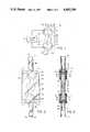
- FIG. 2is an elevation view of the cassette.
- FIG. 3is a side cross-sectional view taken along line 3--3 of FIG. 2.
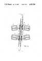
- FIG. 4is a sectional view of the cassette in a metering device.
- FIG. 1Illustrated in schematic fashion in FIG. 1, and generally designated at 10, is a metering device for intravenous fluids constructed in accordance with the present invention.
- the cassette 12has formed within it a metering chamber 14 of fixed geometric shape and volume.
- the metering chamber 14is of a lenticular, or lens-like, shape and is constructed to have a volume equal to a standard IV drop size, preferably 0.1 milliliters, or 0.1 cc.
- the metering chamber 14is defined between a pair of concave side walls 16 and 18 which are shaped and sized to give the metering chamber 14 the preselected desired size.
- a pressure transmitting membrane 20divides the metering chamber 14 into a pair of compartments 22 and 24, formed on opposite sides of the membrane 20, between the membrane 20 and the respective chamber walls 16 and 18.
- a main inlet tube 25is connected to the cassette 12. Inside the cassette 12, the main inlet tube 26 branches into a pair of inlet tubes 28 and 30 which open respectively into the compartments 22 and 24.
- Each of the inlet tubes 28 and 30has provided in it and is controlled by one of a pair of respective inlet valves 32 and 34. In the illustration of FIG. 1, the inlet valve 32 is shown as closed, while the inlet valve 34 is illustrated as open. Also opening into each of the respective compartments 22 and 24 through the chamber walls 16 and 18 is one of a pair of outlet tubes 36 and 38.
- the outlet tubes 36 and 38join inside the cassette 12 to form a common main outlet tube 40 exiting from the cassette 12.
- the outlet tubes 36 and 38are respectively interrupted and controlled by outlet valves 42 and 44, with the outlet valve 44 being shown closed in FIG. 1 and the outlet valve 42 being shown as open.
- All of the valves 32, 34, 42 and 44 within the cassette 12are operably connected to a timing circuit 46 which controls the opening and closing of the valves.
- the timing circuit 46may be any mechanical or electrical device capable of providing a mechanical or electrical operation of the valves 32, 43, 42, and 44 on a selectable time period basis, but is preferably a solid-state digital circuit which has a selectable time frequency output capable of operating the valves 32, 34, 42, and 44. Such solid-state timing circuits are not described in greater detail here.
- the metering device of FIG. 1functions to both monitor and control the flow of intravenous fluids from an intravenous source into a patient.
- the metering device 10is utilized by connecting an intravenous source of fluid, such as a conventional IV bag or bottle, to the main inlet tube 26 into the cassette 12.
- the fluid in the source of intravenous fluidshould have a head pressure in excess of the blood pressure of the patient.
- the head pressureis typically created by elevating the IV source above the patient, but can also be created by pressurizing the IV source with mechanical pressure or other means.
- the main outlet tube 40 from the cassette 12is then connected through suitable tubing to an intravenous catheter inserted into the arm of the patient.
- Operation of the metering device 10 of FIG. 1is controlled by the timing circuit 46 which acts to alternatively and repetitively close and open pairs of the inlet and outlet valves 32, 34, 42 and 44.
- the inlet and outlet valvesare oppositely paired in their operation, that is to say, the inlet valve 34 and the outlet valve 42 are always simultaneously either opened or closed, while the inlet valve 32 and the outlet valve 44 are also simultaneously either opened or closed.
- the valves 34 and 42are shown as open, while the valves 32 and 44 are shown as closed.
- fluid flowis allowed from the main inlet tube 26, through the inlet tube 28, and the inlet valve 32, into the compartment 22 on the left side of the membrane 20.
- This flowcauses the membrane 20 to be pushed to the right, thereby transmitting the pressure from the source of IV fluid to the fluid in the compartment 24 on the right side of the membrane 20.
- the fluid in the compartment 24is forced out of the outlet tube 38, through the valve 44, and the main outlet tube 40 and then into the patient. Again, fluid is forced out of the compartment 24 until the compartment 22 is entirely filled and then the fluid flow ceases. Fluid flow again remains ceased until the timing circuit 46 again alternates the opening and closing of the valves.
- the metering chamber 14is constructed to be of a preselected volume equal to the volume of a standard intravenous set drop size, such as a volume of 0.1 milliliters, the volume of each of the compartments 22 and 24 when filled will be precisely equal to each other and equal in volume to 0.1 milliliters.
- the metering device 10 of FIG. 1functions to precisely output one pulse equal in volume to 0.1 milliliters, for each actuation of the timing circuit 46.
- the volume of this pulse of fluid which is emitted from the metering device 10remains constant as long as the timing circuit 46 is set for a time period sufficiently long to allow the respective compartment 22 or 24 being filled to completely fill with fluid before the operation of the valves is reversed. If that condition is met, the volume of the pulse of fluid passing through the outlet tube 40 between each actuation of the valves will be precisely 0.1 milliliter.
- FIGS. 2 through 4are the construction details of an actual metering device constructed in accordance with the present invention and operation in accordance with the schematic illustration of FIG. 1.
- a cassette 12constructed as a unitary construction of molded themoplastic material.
- the cassette 12has at its upper end a main inlet tube 26 and at its lower end a main outlet tube 40.
- the main inlet tube 26 and the main outlet tube 40are provided at their ends with respective luer lock connectors 43 and 45 which are designed to allow a secure luer lock attachment between the cassette 12 and other portions of an intravenous feeding system incorporating therein the cassette 12 of the metering device 10 of the present invention.
- the inlet valves 32 and 34are each formed from valve chambers 50 and 52 which are formed as outwardly extending open apertures in the body of the cassette 12.
- Each of the valve chambers 50 and 52is closed by a respective one of valve members 54 and 56, which are resiliently flexible circular disks, formed of silicone elastomer or similar elastic materials, having a thickened valve seat portion formed in the center thereof.
- Each of the valve chambers 50 and 52opens into a respective one of inlet tubes 28 and 30 each of which extends from the respective valve chamber 50 and 52 to open into the metering chamber 14 formed in the center of the cassette 12.
- the metering chamber 14is formed as a lenticular hollow in the center of the cassette 12 and is divided into the compartments 22 and 24 by a silicone membrane 20 integrally molded inside of the cassette 12.
- the membrane 20is mounted along the length of the longitudinal centerline of the cassette 12 and also serves as a dividing partition between the inlet tubes 28 and 30.
- the inlet tubes 28 and 30are relatively narrow, as can be seen by referring to the external view shown in FIG.
- a pair of outlet tubes 36 and 38connect the metering chamber 14 respectively to each of a pair of valves 42 and 44.
- Each of the valves 42 and 44includes a respective valve chamber 58 and 60 similar in shape and arrangement to the valve chambers 50 and 52.
- Each of the valve chambers 58 and 60is closed by a one of respective valve members 62 and 64 which are similar in construction and appearance to the valve members 54 and 56.
- a main outlet tube 40connects through a narrowed opening 66 to a transverse channel connected to the valve chambers 58 and 60.
- FIG. 4Shown in FIG. 4 is an installation in which the cassette 12 illustrated in FIGS. 2 and 3 is used in operation in a metering device.
- the cassette 12is placed in a mounting bracket (not shown) which is mounted on a motive device capable of oscillatory motion (also not shown).
- the oscillating motionis provided by a bi-directional rotational motive device, such as a rotational motor with a cam driven oscillating mechanism, a rotational solenoid, or any other oscillating mechanical motive device.
- the oscillating mechanical deviceis operated by the timing circuit 46 as illustrated in FIG. 1.
- the oscillating motive devicecauses the cassette 12 itself to oscillate backwards and forwards through a small arc about an axis centered in the metering chamber 14. The oscillation of the cassette 12 in FIG.
- valve operators 70are provided externally of the cassette 12. The valve operators are fixed in position in the positions shown in FIG. 4.
- Each of the valve operators 70includes a spring-loaded plunger 72 oriented in a direction so as to extend into one of the valve chambers 54, 56, 58 or 60.
- the plunger 72 of a one of the valve operators 70causes the valve member 56 to be depressed to close the valve 34.
- another of the plungers 72is forced against the valve member 58 to close the valve 42.
- the metering device for intravenous fluids as disclosed in FIGS. 1 through 4is inherently accurate and volumetric in character.
- the apparatusis completely volumetric in character in that for each switching of the timing circuit 46, one pulse of fluid equal in volume to the metering chamber 14 is forced from the device into the patient.
- the volume of each pulse of fluid which is introduced into the patientcan be accurately controlled. Since these metered amounts of fluid are precisely accurate in volume and since the timing of the switching of the timing circuit 46 can be accurately controlled by well-known electronic devices, the rate of fluid flow through the metering device can be accurately controlled.
- the overall volume of flowcan thus be determined over any time period merely by multiplying the number of operations of the timing circuit times the volume of the metering chamber 14.
- this devicefor metering the flow of intravenous fluids into a patient which result from this pulsed operation. Because the fluid comes out in relatively quick pulses, rather than a slow continuous stream, as in conventional equipment, the flow of fluid out of the catheter into the patient's veins is a series of relatively fast, powerful fluid pulses rather than a continuous low pressure stream. These relatively fast fluid pulses tend to lessen the buildup of fibrin over the end of the catheter inserted into the patient by tending to carry such fibrin fibers away in the fluid pulse exiting from the catheter. Because of the rapidity of these pulses, the IV catheter is less likely to be clogged by fibrin buildup than in an installtion using a slow, continuous flow.
- the size of the chambercan be constructed so as to correspond to the present standard in practice in drop size measured in the field.
- the volume of the metering chamber 14 in the cassette 12be selected so as to correspond to a volume of 0.1 milliliters. It is currently standard practice in hospitals to set the rate of fluid flow of intravenous fluid into a patient using a drip chamber in which drops are counted. In that practice with most equipment it is generally considered that 10 drops constitute 1 milliliter of fluid flow. Other widely used equipment has drop sizes of one fifteenth, one twentieth and one sixtieth of a milliliter and the volume of the metering chamber 14 can also be selected to match one of these volumes.
- the hospital staffBy providing that a similar amount exits from the metering device 10 during each of its operations, and by providing that the cassette 12 oscillates in a fashion which can be readily viewed, the hospital staff utilizing this equipment can gain a ready appreciation of the amount of fluid being introduced into a patient since the rate of oscillation of the cassette 12 corresponds exactly to the rate of drop flow which they have historically been required to count in setting up intravenous intallations.
- the apparatus of the present inventionis particularly well adapted to being utilized in present hospital environments with a minimum of retraining of staff or customization to new techniques.
- the total volume of fluid metered by the deviceequals the volume of the metering chamber 14 times the number of operations of the timing circuit 46, if the volume of the metering chamber 14 is 0.1 milliliter, a simple division of the rate of switching of the timing circuit 46 by 10 gives the total flow rate in milliliters. Obviously, if the volume of the metering chamber 14 is selected instead to match another of the standard flow rates, division in this calculation would change.
Landscapes
- Health & Medical Sciences (AREA)
- Vascular Medicine (AREA)
- Engineering & Computer Science (AREA)
- Anesthesiology (AREA)
- Biomedical Technology (AREA)
- Heart & Thoracic Surgery (AREA)
- Hematology (AREA)
- Life Sciences & Earth Sciences (AREA)
- Animal Behavior & Ethology (AREA)
- General Health & Medical Sciences (AREA)
- Public Health (AREA)
- Veterinary Medicine (AREA)
- Infusion, Injection, And Reservoir Apparatuses (AREA)
Abstract
Description
Claims (8)
Priority Applications (1)
| Application Number | Priority Date | Filing Date | Title |
|---|---|---|---|
| US06/342,100US4493709A (en) | 1982-01-25 | 1982-01-25 | Metering device for intravenous fluids |
Applications Claiming Priority (1)
| Application Number | Priority Date | Filing Date | Title |
|---|---|---|---|
| US06/342,100US4493709A (en) | 1982-01-25 | 1982-01-25 | Metering device for intravenous fluids |
Publications (1)
| Publication Number | Publication Date |
|---|---|
| US4493709Atrue US4493709A (en) | 1985-01-15 |
Family
ID=23340327
Family Applications (1)
| Application Number | Title | Priority Date | Filing Date |
|---|---|---|---|
| US06/342,100Expired - Fee RelatedUS4493709A (en) | 1982-01-25 | 1982-01-25 | Metering device for intravenous fluids |
Country Status (1)
| Country | Link |
|---|---|
| US (1) | US4493709A (en) |
Cited By (20)
| Publication number | Priority date | Publication date | Assignee | Title |
|---|---|---|---|---|
| US4602249A (en)* | 1984-05-21 | 1986-07-22 | Quest Medical, Inc. | Method and apparatus for detecting leaking valves in a volumetric infusion device |
| US4601702A (en)* | 1984-05-21 | 1986-07-22 | Quest Medical, Inc. | Volumetric infusion actuator |
| US4627419A (en)* | 1984-08-29 | 1986-12-09 | The Board Of Regents, The University Of Texas | Blood pump apparatus and method |
| US4684368A (en)* | 1984-06-01 | 1987-08-04 | Parker Hannifin Corporation | Inverted pump |
| US5382230A (en)* | 1991-12-16 | 1995-01-17 | Thomas Jefferson University | Vascular access sheath for interventional devices |
| EP1214954A1 (en)* | 2000-12-12 | 2002-06-19 | Jakob Bösherz | Medical fluid pump and medical treatment device for fluid delivery to the human or animal body |
| US20040087911A1 (en)* | 2002-10-31 | 2004-05-06 | Feliciano Ari J. | Quick flow control for flexible tubing |
| US20050267402A1 (en)* | 2004-05-27 | 2005-12-01 | Janice Stewart | Multi-state alarm system for a medical pump |
| US20050277873A1 (en)* | 2004-05-27 | 2005-12-15 | Janice Stewart | Identification information recognition system for a medical device |
| US20050277890A1 (en)* | 2004-05-27 | 2005-12-15 | Janice Stewart | Medical device configuration based on recognition of identification information |
| US20070179438A1 (en)* | 2006-01-30 | 2007-08-02 | Alcon, Inc. | Surge suppression method |
| US20080312578A1 (en)* | 2007-04-12 | 2008-12-18 | Defonzo Stephan A | Dialysis catheter |
| US20100209268A1 (en)* | 2009-02-18 | 2010-08-19 | Davis David L | Low cost disposable infusion pump |
| US20100211002A1 (en)* | 2009-02-18 | 2010-08-19 | Davis David L | Electromagnetic infusion pump with integral flow monitor |
| US20100209267A1 (en)* | 2009-02-18 | 2010-08-19 | Davis David L | Infusion pump with integrated permanent magnet |
| US8323492B2 (en) | 2007-10-24 | 2012-12-04 | Baxter International Inc. | Hemodialysis system having clamping mechanism for peristaltic pumping |
| US10578098B2 (en) | 2005-07-13 | 2020-03-03 | Baxter International Inc. | Medical fluid delivery device actuated via motive fluid |
| WO2020167704A1 (en)* | 2019-02-12 | 2020-08-20 | Amgen Inc. | Continuous dosing systems and approaches |
| US11478578B2 (en) | 2012-06-08 | 2022-10-25 | Fresenius Medical Care Holdings, Inc. | Medical fluid cassettes and related systems and methods |
| US20220339346A1 (en)* | 2021-04-23 | 2022-10-27 | Insulet Corporation | Dispensing device for wearable drug delivery device |
Citations (14)
| Publication number | Priority date | Publication date | Assignee | Title |
|---|---|---|---|---|
| US16284A (en)* | 1856-12-23 | Improved device for operating flu i d-m eters by hand | ||
| FR1077943A (en)* | 1953-05-30 | 1954-11-12 | Auxiliaire De Verification Et | Instruments for measuring small gas flow rates |
| GB1115231A (en)* | 1964-11-04 | 1968-05-29 | Christopher Ian Arthur Ellis | Improved dispensing device |
| US4121584A (en)* | 1976-10-15 | 1978-10-24 | R. Scott Turner | Method and apparatus for controlling the dispensing of fluid |
| US4191184A (en)* | 1977-01-06 | 1980-03-04 | Carlisle Jeffrey A | Intravenous infusion regulation system with reciprocal metering means |
| US4205238A (en)* | 1978-02-17 | 1980-05-27 | Baxter Travenol Laboratories, Inc. | Digital electronic apparatus and casette sized for intravenous fluid-flow limiting equipment |
| US4204538A (en)* | 1978-06-07 | 1980-05-27 | Imed Corporation | Cassette for intravenous controller |
| US4207871A (en)* | 1978-06-07 | 1980-06-17 | Imed Corporation | System for controlling the flow of intravenous fluids to a patient |
| US4230244A (en)* | 1979-08-30 | 1980-10-28 | Baxter Travenol Laboratories, Inc. | Fluid-flow limiting apparatus for use with intravenous-solution administering equipment |
| US4261356A (en)* | 1978-10-23 | 1981-04-14 | Baxter Travenol Laboratories, Inc. | Method and apparatus for controlling the dispensing of fluid |
| US4262668A (en)* | 1979-04-06 | 1981-04-21 | Baxter Travenol Laboratories, Inc. | Fixed volume infusion device |
| US4262824A (en)* | 1978-02-17 | 1981-04-21 | Baxter Travenol Laboratories, Inc. | Low-current E-frame electronic magnet with a permanent magnet armature for an I. V. valving controller |
| US4304260A (en)* | 1979-11-01 | 1981-12-08 | Turner Charles R | Flexible diaphragm valve device |
| SU1025728A1 (en)* | 1981-06-02 | 1983-06-30 | Коммунарский горно-металлургический институт | Blast furnace main trough |
- 1982
- 1982-01-25USUS06/342,100patent/US4493709A/ennot_activeExpired - Fee Related
Patent Citations (14)
| Publication number | Priority date | Publication date | Assignee | Title |
|---|---|---|---|---|
| US16284A (en)* | 1856-12-23 | Improved device for operating flu i d-m eters by hand | ||
| FR1077943A (en)* | 1953-05-30 | 1954-11-12 | Auxiliaire De Verification Et | Instruments for measuring small gas flow rates |
| GB1115231A (en)* | 1964-11-04 | 1968-05-29 | Christopher Ian Arthur Ellis | Improved dispensing device |
| US4121584A (en)* | 1976-10-15 | 1978-10-24 | R. Scott Turner | Method and apparatus for controlling the dispensing of fluid |
| US4191184A (en)* | 1977-01-06 | 1980-03-04 | Carlisle Jeffrey A | Intravenous infusion regulation system with reciprocal metering means |
| US4262824A (en)* | 1978-02-17 | 1981-04-21 | Baxter Travenol Laboratories, Inc. | Low-current E-frame electronic magnet with a permanent magnet armature for an I. V. valving controller |
| US4205238A (en)* | 1978-02-17 | 1980-05-27 | Baxter Travenol Laboratories, Inc. | Digital electronic apparatus and casette sized for intravenous fluid-flow limiting equipment |
| US4204538A (en)* | 1978-06-07 | 1980-05-27 | Imed Corporation | Cassette for intravenous controller |
| US4207871A (en)* | 1978-06-07 | 1980-06-17 | Imed Corporation | System for controlling the flow of intravenous fluids to a patient |
| US4261356A (en)* | 1978-10-23 | 1981-04-14 | Baxter Travenol Laboratories, Inc. | Method and apparatus for controlling the dispensing of fluid |
| US4262668A (en)* | 1979-04-06 | 1981-04-21 | Baxter Travenol Laboratories, Inc. | Fixed volume infusion device |
| US4230244A (en)* | 1979-08-30 | 1980-10-28 | Baxter Travenol Laboratories, Inc. | Fluid-flow limiting apparatus for use with intravenous-solution administering equipment |
| US4304260A (en)* | 1979-11-01 | 1981-12-08 | Turner Charles R | Flexible diaphragm valve device |
| SU1025728A1 (en)* | 1981-06-02 | 1983-06-30 | Коммунарский горно-металлургический институт | Blast furnace main trough |
Cited By (33)
| Publication number | Priority date | Publication date | Assignee | Title |
|---|---|---|---|---|
| US4602249A (en)* | 1984-05-21 | 1986-07-22 | Quest Medical, Inc. | Method and apparatus for detecting leaking valves in a volumetric infusion device |
| US4601702A (en)* | 1984-05-21 | 1986-07-22 | Quest Medical, Inc. | Volumetric infusion actuator |
| US4684368A (en)* | 1984-06-01 | 1987-08-04 | Parker Hannifin Corporation | Inverted pump |
| US4627419A (en)* | 1984-08-29 | 1986-12-09 | The Board Of Regents, The University Of Texas | Blood pump apparatus and method |
| US5382230A (en)* | 1991-12-16 | 1995-01-17 | Thomas Jefferson University | Vascular access sheath for interventional devices |
| EP1214954A1 (en)* | 2000-12-12 | 2002-06-19 | Jakob Bösherz | Medical fluid pump and medical treatment device for fluid delivery to the human or animal body |
| US20040087911A1 (en)* | 2002-10-31 | 2004-05-06 | Feliciano Ari J. | Quick flow control for flexible tubing |
| US6770057B2 (en)* | 2002-10-31 | 2004-08-03 | Hewlett-Packard Development Company, L.P. | Quick flow control for flexible tubing |
| US7927313B2 (en) | 2004-05-27 | 2011-04-19 | Baxter International Inc. | Medical device configuration based on recognition of identification information |
| US20050267402A1 (en)* | 2004-05-27 | 2005-12-01 | Janice Stewart | Multi-state alarm system for a medical pump |
| US20050277890A1 (en)* | 2004-05-27 | 2005-12-15 | Janice Stewart | Medical device configuration based on recognition of identification information |
| US10518030B2 (en) | 2004-05-27 | 2019-12-31 | Baxter International Inc. | Medical fluid therapy system having multi-state alarm feature |
| US9925334B2 (en) | 2004-05-27 | 2018-03-27 | Baxter International Inc. | Multi-state alarm system for a medical pump |
| US8961461B2 (en) | 2004-05-27 | 2015-02-24 | Baxter International Inc. | Multi-state alarm system for a medical pump |
| US11583628B2 (en) | 2004-05-27 | 2023-02-21 | Baxter International Inc. | Medical fluid therapy system having multi-state alarm feature |
| US20050277873A1 (en)* | 2004-05-27 | 2005-12-15 | Janice Stewart | Identification information recognition system for a medical device |
| US12392335B2 (en) | 2005-07-13 | 2025-08-19 | Baxter International Inc. | Medical fluid pumping system having backflow prevention |
| US11384748B2 (en) | 2005-07-13 | 2022-07-12 | Baxter International Inc. | Blood treatment system having pulsatile blood intake |
| US10670005B2 (en) | 2005-07-13 | 2020-06-02 | Baxter International Inc. | Diaphragm pumps and pumping systems |
| US10590924B2 (en) | 2005-07-13 | 2020-03-17 | Baxter International Inc. | Medical fluid pumping system including pump and machine chassis mounting regime |
| US10578098B2 (en) | 2005-07-13 | 2020-03-03 | Baxter International Inc. | Medical fluid delivery device actuated via motive fluid |
| US20070179438A1 (en)* | 2006-01-30 | 2007-08-02 | Alcon, Inc. | Surge suppression method |
| US8323228B2 (en) | 2007-04-12 | 2012-12-04 | Rex Medical L.P. | Dialysis catheter |
| US20080312578A1 (en)* | 2007-04-12 | 2008-12-18 | Defonzo Stephan A | Dialysis catheter |
| US8323492B2 (en) | 2007-10-24 | 2012-12-04 | Baxter International Inc. | Hemodialysis system having clamping mechanism for peristaltic pumping |
| US20100209267A1 (en)* | 2009-02-18 | 2010-08-19 | Davis David L | Infusion pump with integrated permanent magnet |
| US8353864B2 (en) | 2009-02-18 | 2013-01-15 | Davis David L | Low cost disposable infusion pump |
| US8197235B2 (en) | 2009-02-18 | 2012-06-12 | Davis David L | Infusion pump with integrated permanent magnet |
| US20100211002A1 (en)* | 2009-02-18 | 2010-08-19 | Davis David L | Electromagnetic infusion pump with integral flow monitor |
| US20100209268A1 (en)* | 2009-02-18 | 2010-08-19 | Davis David L | Low cost disposable infusion pump |
| US11478578B2 (en) | 2012-06-08 | 2022-10-25 | Fresenius Medical Care Holdings, Inc. | Medical fluid cassettes and related systems and methods |
| WO2020167704A1 (en)* | 2019-02-12 | 2020-08-20 | Amgen Inc. | Continuous dosing systems and approaches |
| US20220339346A1 (en)* | 2021-04-23 | 2022-10-27 | Insulet Corporation | Dispensing device for wearable drug delivery device |
Similar Documents
| Publication | Publication Date | Title |
|---|---|---|
| US4493709A (en) | Metering device for intravenous fluids | |
| US4199307A (en) | Medical infusion system | |
| US3559644A (en) | Liquid infusion apparatus | |
| SU1087053A3 (en) | Device for intravenous injections of liquid | |
| US4657486A (en) | Portable infusion device | |
| US4273121A (en) | Medical infusion system | |
| US3994294A (en) | Syringe pump valving and motor direction control system | |
| US4842584A (en) | Disposable fluid infusion pumping chamber cassette and drive mechanism thereof | |
| US4936760A (en) | Volumetric infusion pump | |
| US4519792A (en) | Infusion pump system | |
| US5098377A (en) | Multimodal displacement pump and dissolution system for same | |
| US5344292A (en) | Fluid pumping system and apparatus | |
| US4191184A (en) | Intravenous infusion regulation system with reciprocal metering means | |
| US9713667B2 (en) | System and method for delivering a target volume of fluid | |
| EP0258424B1 (en) | Intravenous line valving system | |
| US4921480A (en) | Fixed volume infusion device | |
| US4335835A (en) | Device for the intravenous or enteric infusion of liquids into the human body at a predetermined constant rate | |
| US4504263A (en) | Flow rate monitor with optical sensing chamber | |
| JP2763005B2 (en) | Pump cassette for liquid injection and fluid pump cassette device using the same | |
| US4936832A (en) | Ambulatory disposable infusion delivery system | |
| US4140118A (en) | Cassette chamber for intravenous delivery system | |
| US3298367A (en) | Apparatus for administering parenteral liquids | |
| US4534764A (en) | Sequential medication delivery device | |
| EP0266590B1 (en) | Infusion device | |
| JPH0622634B2 (en) | Pulse type liquid injection device |
Legal Events
| Date | Code | Title | Description |
|---|---|---|---|
| AS | Assignment | Owner name:QUEST MEDICAL, INC., 3312 WILEY POST ROAD, CARROLL Free format text:ASSIGNMENT OF ASSIGNORS INTEREST.;ASSIGNOR:SMITH, GORDON E.;REEL/FRAME:004288/0380 Effective date:19840730 Owner name:QUEST MEDICAL, INC.,TEXAS Free format text:ASSIGNMENT OF ASSIGNORS INTEREST;ASSIGNOR:SMITH, GORDON E.;REEL/FRAME:004288/0380 Effective date:19840730 | |
| FEPP | Fee payment procedure | Free format text:PAYOR NUMBER ASSIGNED (ORIGINAL EVENT CODE: ASPN); ENTITY STATUS OF PATENT OWNER: SMALL ENTITY | |
| REMI | Maintenance fee reminder mailed | ||
| FPAY | Fee payment | Year of fee payment:4 | |
| SULP | Surcharge for late payment | ||
| AS | Assignment | Owner name:KENDALL MCGAW LABORATORIES, INC., A CORP. OF OH, C Free format text:ASSIGNMENT OF ASSIGNORS INTEREST.;ASSIGNOR:QUEST MEDICAL, INC.;REEL/FRAME:005330/0897 Effective date:19870902 | |
| AS | Assignment | Owner name:WELLS FARGO BANK, N.A. Free format text:SECURITY INTEREST;ASSIGNOR:MCGAW, INC., A CORP. OF OH;REEL/FRAME:005477/0809 Effective date:19901022 | |
| AS | Assignment | Owner name:KENDALL MCGAW LABORATORIES, INC. AN OH CORPORAT Free format text:RELEASED BY SECURED PARTY;ASSIGNOR:MANUFACTURERS HANOVER TRUST COMPANY;REEL/FRAME:005709/0001 Effective date:19901015 | |
| AS | Assignment | Owner name:KENDALL MCGAW LABORATORIES, INC., AN OH CORP. Free format text:RELEASED BY SECURED PARTY;ASSIGNOR:MANUFACTURERS HANOVER TRUST COMPANY;REEL/FRAME:005515/0206 Effective date:19901015 | |
| AS | Assignment | Owner name:MCGAW, INC., MORAINE, MONTGOMERY COUNTY, A CORP. O Free format text:MERGER;ASSIGNOR:MG ACQUISITION CORP. A CORP. OF DE (MERGED TO) KENDALL MCGAW LABORATORIES, INC., A CORP. OF OHIO;REEL/FRAME:005640/0520 Effective date:19910205 | |
| AS | Assignment | Owner name:GENERAL ELECTRIC CAPITAL CORPORATION, A NEW YORK C Free format text:ASSIGNMENT OF ASSIGNORS INTEREST.;ASSIGNOR:MCGAW, INC., A DELAWARE CORP.;REEL/FRAME:006073/0600 Effective date:19920401 | |
| AS | Assignment | Owner name:MCGAW, INC. A CORP. OF DELAWARE Free format text:SECURITY INTEREST;ASSIGNOR:WELLS FARGO BANK, N.A.;REEL/FRAME:006139/0057 Effective date:19920401 | |
| REMI | Maintenance fee reminder mailed | ||
| LAPS | Lapse for failure to pay maintenance fees | ||
| FP | Lapsed due to failure to pay maintenance fee | Effective date:19970115 | |
| STCH | Information on status: patent discontinuation | Free format text:PATENT EXPIRED DUE TO NONPAYMENT OF MAINTENANCE FEES UNDER 37 CFR 1.362 |