US4493319A - Ring applicator having floating inner tube - Google Patents
Ring applicator having floating inner tubeDownload PDFInfo
- Publication number
- US4493319A US4493319AUS06/521,020US52102083AUS4493319AUS 4493319 AUS4493319 AUS 4493319AUS 52102083 AUS52102083 AUS 52102083AUS 4493319 AUS4493319 AUS 4493319A
- Authority
- US
- United States
- Prior art keywords
- tube
- rearward
- anatomical
- instrument
- handle
- Prior art date
- Legal status (The legal status is an assumption and is not a legal conclusion. Google has not performed a legal analysis and makes no representation as to the accuracy of the status listed.)
- Expired - Lifetime
Links
- 238000009810tubal ligationMethods0.000claimsabstractdescription10
- 239000013307optical fiberSubstances0.000claimsabstractdescription6
- 239000012530fluidSubstances0.000claimsabstract3
- 239000003193general anesthetic agentSubstances0.000claimsabstract2
- 230000003287optical effectEffects0.000claimsdescription6
- 239000011810insulating materialSubstances0.000claimsdescription3
- 210000003813thumbAnatomy0.000claimsdescription3
- 239000004677NylonSubstances0.000claimsdescription2
- 210000003811fingerAnatomy0.000claimsdescription2
- 238000003780insertionMethods0.000claimsdescription2
- 230000037431insertionEffects0.000claimsdescription2
- 229920001778nylonPolymers0.000claimsdescription2
- 206010002091AnaesthesiaDiseases0.000abstractdescription9
- 230000037005anaesthesiaEffects0.000abstractdescription9
- 238000000034methodMethods0.000abstractdescription8
- 210000003101oviductAnatomy0.000abstractdescription6
- 238000004140cleaningMethods0.000description6
- 239000000835fiberSubstances0.000description5
- 238000005286illuminationMethods0.000description5
- 238000001356surgical procedureMethods0.000description4
- 239000008280bloodSubstances0.000description3
- 210000004369bloodAnatomy0.000description3
- 230000001954sterilising effectEffects0.000description3
- 238000004659sterilization and disinfectionMethods0.000description3
- 230000000694effectsEffects0.000description2
- 238000012423maintenanceMethods0.000description2
- 239000000463materialSubstances0.000description2
- 230000002028prematureEffects0.000description2
- 230000011664signalingEffects0.000description2
- 239000004809TeflonSubstances0.000description1
- 229920006362Teflon®Polymers0.000description1
- 241000321728Tritogonia verrucosaSpecies0.000description1
- 206010045178Tunnel visionDiseases0.000description1
- 210000000683abdominal cavityAnatomy0.000description1
- 210000003484anatomyAnatomy0.000description1
- 230000006835compressionEffects0.000description1
- 238000007906compressionMethods0.000description1
- 238000010276constructionMethods0.000description1
- 238000011109contaminationMethods0.000description1
- 201000010099diseaseDiseases0.000description1
- 208000037265diseases, disorders, signs and symptomsDiseases0.000description1
- 230000008030eliminationEffects0.000description1
- 238000003379elimination reactionMethods0.000description1
- 210000004247handAnatomy0.000description1
- 208000014674injuryDiseases0.000description1
- 239000012212insulatorSubstances0.000description1
- 238000002357laparoscopic surgeryMethods0.000description1
- 239000002184metalSubstances0.000description1
- 239000000615nonconductorSubstances0.000description1
- 230000010355oscillationEffects0.000description1
- 230000003534oscillatory effectEffects0.000description1
- 238000003825pressingMethods0.000description1
- 238000012414sterilization procedureMethods0.000description1
- 238000006467substitution reactionMethods0.000description1
- 230000008733traumaEffects0.000description1
- 210000001177vas deferenAnatomy0.000description1
Images


Classifications
- A—HUMAN NECESSITIES
- A61—MEDICAL OR VETERINARY SCIENCE; HYGIENE
- A61F—FILTERS IMPLANTABLE INTO BLOOD VESSELS; PROSTHESES; DEVICES PROVIDING PATENCY TO, OR PREVENTING COLLAPSING OF, TUBULAR STRUCTURES OF THE BODY, e.g. STENTS; ORTHOPAEDIC, NURSING OR CONTRACEPTIVE DEVICES; FOMENTATION; TREATMENT OR PROTECTION OF EYES OR EARS; BANDAGES, DRESSINGS OR ABSORBENT PADS; FIRST-AID KITS
- A61F6/00—Contraceptive devices; Pessaries; Applicators therefor
- A61F6/20—Vas deferens occluders; Fallopian occluders
- A61F6/208—Implements for ligaturing
Definitions
- the present inventionrelates to an elastic ring applicator for ligating anatomical elements, and more specifically relates to such an instrument which further includes a highly sensitive signaling means for alerting the surgeon when the applicator is about to deposit the elastic ring.
- the applicatorpreferably also includes means for intraabdominally anesthetizing an anatomical element and for internally viewing the ligation procedure.
- this instrumentis particularly useful for performing female sterilization procedures involving the Fallopian tubes, it may be applied to the vas deferens in the human male, and to other anatomical structures.
- Tubal ligation instrumentshave found world wide acceptance for a wide variety of purposes, but in particular have been used for sterilization.
- U.S. Pat. No. 3,834,392granted to Lampman et al on Sep. 10, 1974, a laparoscope system is disclosed whereby a single unit contains the power source to provide illumination, oscillatory electrical power and CO 2 gas for laparoscopy. CO 2 gas under pressure is passed into the body through a needle. A trocar and cannula are inserted into the gas-filled abdominal cavity. A laparoscope connected to a source of illumination is inserted into the body cavity through the cannula. The Fallopian tubes are then identified and forceps are inserted through the cannula into the body cavity.
- the forcepsare manipulated to successively close the passage through each Fallopian tube either by means of sending electrical oscillations through the forceps to simultaneously cut, seal and cauterize each tube in turn, or by means of a special type of clamp which clamps the passage shut.
- the Watson devicediscloses the use of an inner tube and an outer tube together with a biasing means, typically a helical compression spring, to warn the surgeon of the impending discharge of the elastic ring.
- a biasing meanstypically a helical compression spring
- Such a springis not helpful during the loading of elastic rings, particularly when spring resistance is counted upon to provide the necessary resistance for ring loading onto the inner tube.
- Watsondiscloses that elastic rings are loaded onto the distal end of an inner tube by forcing them with a conical ring dilator.
- the inner tubeis caused to protrude from the outer tube, a distance equal to the width(s) of the ring(s) placed on the inner tube.
- only the force of the springcauses the inner tube to protrude beyond the outer tube.
- the springsometimes weakens to such an extent that it becomes difficult or impossible to load rings onto the inner tube.
- the springplays an important role in the surgeon's use of the Watson device.
- the surgeonretracts the slidable gripping means to a position of encountering the resistance of the helical spring.
- the surgeonis able to feel when the instrument is in proper orientation for applying anesthesia.
- the surgeonupon encountering the resistance due to the spring, is informed by the yieldable resistance that he encounters that the elastic ring is about to be ejected from the inner tube.
- the springhas become weakened after extended use it is capable of giving a false resistance feel which could even result in the surgeon's premature ejection of a ring.
- the springwith its helical shape and many crevices, presents a cleaning problem.
- a further problem with the Watson deviceconcerns the size of the incision necessary to insert the instrument.
- the diameter of the outer housing tube in the Watson deviceis approximately one-half inch.
- a rather large trocarhas been necessary to perform the ligation procedure. This sometimes causes serious psychological problems for the patient undergoing the ligation operation.
- the trauma to the patientis greater due to the incision diameter. There is also a greater chance of herniation due to the larger incision.
- a further problem with the Watson deviceconcerns the rotation of the device within the cannula. It is advantageous to rotate the device within the cannula to grasp the anatomical element at the proper location. If the device is tightly held by the cannula valve, both the device and the cannula must rotate to grasp the anatomical element in the proper location. If the incision is made as small as possible to prevent gas leakage, it becomes difficult to rotate the cannula in the incision. If the incision is enlarged to permit rotation of the cannula, there may be leakage of gas from the cavity. The alternative method of rotation, holding the cannula while the device is rotated, requires an additional pair of hands which makes use of the instrument more difficult and may result in contamination of the sterile field.
- a further problem with the Watson deviceis the disassembly and assembly of the device during maintenance and cleaning.
- two stepsmust be performed; removal of the pin and unscrewing the inner tube.
- five elementsmust be aligned; the hole in the inner member, the inner tube slot, the outer tube slot, the hole in the slidable finger grip and the pin.
- Another important object of the present inventionis to enable the elimination of both the springs and the slots shown in the Watson device, thereby providing easier cleaning of the instrument, easier assembly and disassembly, easier loading and more predictable use of the instrument over an extended period of time.
- a ring application instrument in accordance with this inventionincludes an elongated inner member having an anatomical grasping means such as forceps at its forward end, said inner member grasping means being slidable in an inner tube which is a support means for one or more elastic rings.
- An outer tubeis provided within which the inner tube fits in a freely slidable and rotatable manner.
- a manually engagable locking meansenables the surgeon selectively to lock the inner tube, relative to the outer tube, in a position to accept loading of one or more elastic rings.
- a manually engagable stop meansis provided which is operative between the inner and outer tubes to prevent ejection of a second elastic ring after ejection of a first elastic ring.
- the elongated inner membermay, if desired, be of hollow construction to hold either an optical device for viewing the surgical procedure or for carrying anesthesia to the element to be ligated.
- the elongated inner membermay be further adapted to be used in conjunction with an electrosurgical device.
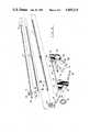
- FIG. 1is a side elevation of a ring applicator comprising one specific embodiment of the present invention.
- FIG. 2is an exploded view of the ring applicator of FIG. 1.
- FIGS. 3A, 3B and 3Care side views of the forward end of the ring applicator of FIGS. 1 and 2, illustrating a preferred procedure for loading the elastic rings.
- FIG. 4Ais a side view of a fully loaded ring applicator with fully extended grasping means ready to grasp an anatomical element.
- FIG. 4Bis an enlarged, fragmentary cross-sectional view of the forward end of the ring applicator shown in FIG. 4A.
- FIG. 5is a side view of the ring applicator of FIG. 4A after it has grasped the anatomical element and is drawing it into the inner applicator tube.
- FIGS. 6A, 6B and 7are cross-sectional and side views illustrating the operation of one form of ring applicator device in accordance with the present invention.
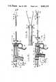
- FIG. 8is a side view of the ring applicator, with certain portions cut away and shown in cross section in order to reveal important details.
- FIG. 9is a perspective view of the ring applicator in a locked position.
- FIGS. 10, 11A and 11Bare side (enlarged), and cross-sectional views, respectively, of a ring applicator utilizing an optic viewing system with a fiber optic illumination system in accordance with this invention.
- FIG. 12is a cross-sectional view of a modified form of applicator, showing an apparatus for performing electrosurgery in accordance with the present invention.
- the ring applicator device of the present inventionis designated as 10. Furthermore, with respect to the ring applicator 10 and/or any individual part thereof, the side or end closest to the patient shall be designated forward, and the side or end closest to the surgeon shall be designated rearward.
- the ring applicator 10consists of an outer tube 11 housing an inner tube 12.
- the diameters of tubes 11 and 12are such that inner tube 12 has a close sliding fit within outer tube 11.
- Inner tube 12houses an inner rod 13 having spring-like forceps 21 at its forward end. Attached to the rearward end of inner tube 12 is flange plate 30 having an additional hole 34.
- Inner rod 13is adapted to fit into inner tube 12 by pressing the forceps 21 together and inserting them through the rearward end of inner tube 12.
- the inner tube 12fits within outer tube 11 by sliding the forward end of inner tube 12 into the rearward end of outer tube 11.
- Ring applicator 10also includes a pistol grip handle adapted to fit in the surgeon's hand.
- the pistol grip handleincludes a slidable (with respect to the outer tube 11) forward handle 14 and a stationary rearward handle 15.
- Rearward handle 15engages rods 19 and 20 which are fixedly attached to forward handle 14.
- rearward handle 15engages rod 20 in cylindrical passageway 26, and engages rod 19 in cylindrical passageway 35.
- the axes of rods 19 and 20 and passageways 26 and 35are parallel so that rods 19 and 20 easily slide in rearward handle 15.
- Forward handle 14 and rearward handle 15engage outer tube 11 through cylindrical passageways 24 and 25 respectively.
- outer tube 11, containing inner tube 12 and inner rod 13is fed forward end first through cylindrical passageway 25 and then through cylindrical passageway 24.
- Flange plate 30, attached to inner tube 12,must be aligned so that hole 34 engages rod 20 attached to forward handle 14.
- inner tube 12is freely slidable over that portion of rod 20 rearward of lip 37.
- Outer tube 11is fixedly attached to rearward handle 15 by rings 36.
- Screw 32attaches to the rearward end of rod 20, having a threaded bore 70, to accept screw 32 as shown clearly in FIG. 8.
- valve 33which is adapted to screw into the rearward end of inner rod 13 attaches inner rod 13 to flange plate 31.
- the inner rod 13is fixedly attached to forward handle 14.
- inner rod 13 having forceps 21 at its forward end and flange plate 31 attached to its rearward endis fixedly attached to forward handle 14.
- outer tube 11is fixedly attached to rearward handle 15. Since forward handle 14 is adapted slidably to engage rearward handle 15, the act of sliding the forward handle 14 rearwardly causes the forceps 21 to be drawn into the outer tube 11. Similarly, by sliding forward handle 14 forwardly, forceps 21 are caused to extend out of the forward end of outer tube 11.
- Inner rod 13fixedly attached to forward handle 14, by necessity has a slidable range equal to the slidable range of forward handle 14.
- Forward handle 14can be slid in a rearward direction until the forward face of rearward handle 15 abuts forward handle 14 as shown in FIG. 7.
- Forward handle 14also has a forward slidable limit at the point where the forward face of flange plate 31 abuts the rearward face of flange plate 30 which in turn abuts the rearward face of rearward handle 15, as shown in FIG. 4A.
- inner tube 12has a forward and rearward slidable limit.
- forward handle 14may be slid forwardly until flange plate 31 abuts flange plate 30. At this point, the forward end of inner tube 12 protrudes beyond the forward end of outer tube 11 a distance approximately equal to the width of two rings and the forceps 21 protrude beyond inner tube 12. With flange plate 30 abutted to rearward handle 15, forward handle 14 may be slid rearwardly until lip 37 of rod 20 encounters flange plate 30. With further rearward movement of forward handle 14, inner tube 12 will slide rearwardly in relation to outer tube 11. This slidable span will result in ring ejection.
- Forward handle 14 and rearward handle 15are shown in the drawings as having a shape substantially like a pistol grip.
- the rotatable ring 16is adapted for engagement by the surgeon's thumb.
- the ring 16is rotatable on rearward handle 15 and attached thereto by a screw 38.
- the screw 38is unthreaded in the rearward handle 15 and is only screwed into the ring 16; thus it is rotatable.
- the rotatable ring 16provides a comfortable means of grasping the ring applicator 10, whether the surgeon be left or right-handed. Since the ring 16 is rotatable, it can move about to fit comfortably on either a right-hand or left-hand thumb.
- forward handle 14, rearward handle 15 and rotatable ring 16are shown as being in a pistol-grip shape, it should, nevertheless, be appreciated that the handles can have other conventional shapes.
- the ring 16can be of a generally U-shaped or generally square-shaped configurations, or others.
- ring applicator 10is shown in a locked position ready to accept loading of elastic rings.
- Ring applicator 10is locked into the loading position by sliding flange plate 30 forward until it abuts the rearward face of rearward handle 15.
- Ring 16is then rotated until latch 18 engages notch 60 in rod 19.
- latch 18engages rod 19, flange plate 30 is held flush against the rearward face of rearward handle 15.
- inner tube 12is unable to slide with respect to outer tube 11.
- inner tube 12extends beyond the forward end of outer tube 11 a distance slightly greater than the width of two elastic rings.
- FIGS. 3A, 3B and 3Cillustrate sequentially the ring loading operation. Ring loading (of itself) is known in the art and is described herein only for purposes of illustration.
- Cone 92is adapted to fit into the forward end of inner tube 12.
- An elastic ring 90is then placed on the tip of cone 92.
- Elastic ring 90is then forced down cone 92 by ring sliding device 93.
- the first elastic ring loaded, ring 90is slid over inner tube 12 until it abuts the forward end of outer tube 11.
- the second ring 91is slid over inner tube 12 until it abuts the first ring 90.
- Many operationssuch as sterilization of females through ligation of Fallopian tubes, require the use of two elastic rings in order to ligate two tubes.
- the surgeoncan perform the entire ligation operation without having to withdraw and reload the ring applicator 10 during surgery.
- FIG. 4Aa fully loaded ring applicator 10 is shown with fully extended forceps 21 ready to grasp anatomical tube 100.
- forward handle 14is in its most forward slidable position.
- outer tube 11 and inner tube 12are also in their most rearward slidable positions.
- the spring-like forceps 21are exposed and opened.
- FIG. 4Bis an enlarged cross-sectional view of the forward end of ring applicator 10 shown in FIG. 4A.
- the open position of the forceps 21is clearly shown as well as the respective positions of elastic rings 90 and 91.
- pin 17rotated into a position between the forward side of rearward handle 15 and the rearward side of forward handle 14, prior to and during the ligation with the first ring to be ejected.
- the diameter of rotatable pin 17approximately equal to the width of elastic ring 90 the surgeon is assured that only the most forward positioned elastic ring 91 will be ejected onto anatomical tube 100 and that elastic ring 90 will remain in place.
- Pin 17is in a position between handles 14 and 15 during ligation of the first anatomical tube 100 and ejection of the first ring 91 as shown in FIGS. 4A, 4B, 5 and 6A.
- the ring applicator 10is shown immediately after the first ring 91 has been ejected to effect ligation of anatomical tube 100.
- rotatable pin 17has been rotated into a position between the forward handle 14 and the rearward handle 15 thereby preventing further sliding of outer tube 11 with respect to inner tube 12 and thereby preventing the ejection of the second elastic ring 90.
- FIG. 6Bis an enlarged cross-sectional view of the forward end of ring applicator 10 of FIG. 6A.
- Anatomical tube 100is grasped by forceps 21 and pulled inside inner tube 12 as inner rod 13 is slid rearwardly with respect to inner tube 12 and outer tube 11.
- inner tube 12is slid rearwardly a distance approximately equal to the width of one elastic ring 91 with respect to outer tube 11 thereby causing elastic ring 91 to be pushed off the end of the inner tube 12.
- This sliding movementis accomplished against the friction of the elastic rings on the inner tube 12, signaling to the surgeon the impending discharge of the elastic ring 91.
- the surgeonfeels a slight snap caused by the sudden ejection of ring 91. In this way, the surgeon can feel when the ligation of anatomical tube 100 is about to occur and when it has been accomplished.
- the surgeonmerely slides the forward handle 14 in a forward direction thereby causing the forceps 21 to protrude from the end of inner tube 12 thereby allowing the (self-opening) forceps 21 to spring open and release anatomical tube 100.
- the same basic sequence of eventsis then undertaken with respect to the second anatomical tube 101 to be ligated.
- the only difference between the first ligation and the second ligationis that to perform the second ligation the rotatable pin 17 must be rotated out of its position between forward handle 14 and rearward handle 15 in order that inner tube 12 can be slid rearwardly to a position where the forward end of outer tube 11 is flush with the forward end of inner tube 12.
- This rearward sliding of inner tube 12 with respect to outer tube 11pushes off the remaining elastic ring 90 (with the same "signals" to the surgeon) into a position around anatomical tube 101 thereby affecting ligation of anatomical tube 101.
- Anatomical tube 101is then released by sliding forward handle 14 in a forward direction to expose and spring open forceps 21.
- the entire deviceis easily disassembled for cleaning, maintenance, sterilization or replacement.
- the separate partscontain mostly smooth, open and easily accessible surfaces. Although it is preferred to clean and sterilize the parts separately, they can be cleaned separately, and then reassembled and sterilized as one unit.
- FIGS. 10, llA and 11BSuch easy assembly and disassembly of the ring applicator 10 permits fast substitution of parts for different embodiments of the present invention.
- FIGS. 10, llA and 11BOne such preferred embodiment is shown in FIGS. 10, llA and 11B.
- the inner rod 13 having two spring-like forceps 21is replaced with a hollow rod 40 containing lenses 41, window 42 and light-carrying optical fibers 43.
- Attached to the forward end of hollow rod 40is a single tong 44 used to hook the anatomical tube 100.
- Tong 44has a spherical tip, to avoid cutting or puncturing the anatomical tube 100.
- the optical fibersrun along the length of hollow rod 40 and parallel to its axis. The positioning of the optical fibers 43 around the interior surface of hollow rod 40 is shown in FIG. 11B.
- Fiber optic connector 45is well known in the art and forms no part of the present invention other than to illustrate the use of the novel forward tip configuration of the present fiber optic embodiment.
- a light-emitting sourceis operationally connected to fiber optic connector 45 which in turn directs illumination through the individual optical fibers 43 running through hollow rod 40. In this way, illumination is provided enabling the surgeon to view the anatomical tube to be ligated. Generally the surgeon views the procedure through eyepiece 46.
- the field of vision for the narrow hollow tube 40 and lenses 41is inherently limited to the available angle ⁇ .
- inner tube 12 and outer tube 11are composed of metal or other opaque materials, the field of view which the surgeon is afforded is considerably narrowed when the inner rod 40 is inside inner tube 12. This "tunnel vision" effect can be lessened by providing windows 47 in the sides of tubes 11 and 12. One window 47 is clearly shown in FIG. 10. A second window 47 is on the opposite side of tubes 11 and 12. These windows 47 give the surgeon a fuller field of vision and allow him to view the periphery around the anatomical element 100 being ligated.
- ring applicator 10 of the present inventionmay be used in conjunction with other optical viewing devices.
- One such device known to the prior artslidably fits over outer tube 11 and is fastened to ring applicator 10 by threadably engaging fastener 61,
- FIG. 12A further embodiment of the present invention is illustrated in FIG. 12.
- the ring applicator 10is combined with an electrosurgical device.
- inner rod 13is replaced with a hollow rod 50 composed of a nonconductor (preferably of nylon) carrying electrical wires 52 and 53.
- Rod 50is hollow with an inner channel 51 which can be used to convey anesthesia to the ligation area.
- wires 52 and 53run within the walls of rod 50. Because the material of rod 50 is an insulator there is no danger of short-circuiting between wires 52 and 53.
- Wires 52 and 53are connected to an electrical supply at the rearward end of hollow rod 50. At the forward end of rod 50 the wires are connected to ordinary spring-like forceps 21 as shown in FIG. 1.
- the inner tube 12 in this configurationis made of an insulating material such as teflon.
- the electrosurgical deviceis a desirable backup system to simultaneously cut, seal and cauterize each anatomical tube.
- Both hollow rod 40 and rod 50have the same dimensions as inner rod 13.
- both the optical viewing and electrosurgical embodiments of the present inventionfit equally well with the ring applicator 10 described herein and in the drawings.
- the diameter of outer tube 11being typically and desirably approximately one-fourth inch, determines the size of the incision made by the surgeon's trocar in the ligation procedure. This is remarkable indeed when compared with available prior art devices.
Landscapes
- Health & Medical Sciences (AREA)
- Reproductive Health (AREA)
- Engineering & Computer Science (AREA)
- Biomedical Technology (AREA)
- Heart & Thoracic Surgery (AREA)
- Vascular Medicine (AREA)
- Life Sciences & Earth Sciences (AREA)
- Animal Behavior & Ethology (AREA)
- General Health & Medical Sciences (AREA)
- Public Health (AREA)
- Veterinary Medicine (AREA)
- Surgical Instruments (AREA)
Abstract
Description
Claims (15)
Priority Applications (1)
| Application Number | Priority Date | Filing Date | Title |
|---|---|---|---|
| US06/521,020US4493319A (en) | 1981-06-29 | 1983-08-08 | Ring applicator having floating inner tube |
Applications Claiming Priority (2)
| Application Number | Priority Date | Filing Date | Title |
|---|---|---|---|
| US27844481A | 1981-06-29 | 1981-06-29 | |
| US06/521,020US4493319A (en) | 1981-06-29 | 1983-08-08 | Ring applicator having floating inner tube |
Related Parent Applications (1)
| Application Number | Title | Priority Date | Filing Date |
|---|---|---|---|
| US27844481AContinuation | 1981-06-29 | 1981-06-29 |
Publications (1)
| Publication Number | Publication Date |
|---|---|
| US4493319Atrue US4493319A (en) | 1985-01-15 |
Family
ID=26959100
Family Applications (1)
| Application Number | Title | Priority Date | Filing Date |
|---|---|---|---|
| US06/521,020Expired - LifetimeUS4493319A (en) | 1981-06-29 | 1983-08-08 | Ring applicator having floating inner tube |
Country Status (1)
| Country | Link |
|---|---|
| US (1) | US4493319A (en) |
Cited By (87)
| Publication number | Priority date | Publication date | Assignee | Title |
|---|---|---|---|---|
| US4628915A (en)* | 1985-05-15 | 1986-12-16 | Chaney John L | Male organ conditioner accessory |
| US4860746A (en)* | 1982-04-20 | 1989-08-29 | Inbae Yoon | Elastic surgical ring clip and ring loader |
| US4920982A (en)* | 1988-06-27 | 1990-05-01 | Vastech Medical Products Inc. | Percutaneous vasectomy method |
| US4990152A (en)* | 1988-10-12 | 1991-02-05 | Inbae Yoon | Applicator device housing multiple elastic ligatures in series and for dilating and applying elastic ligatures onto anatomical tissue |
| US4994079A (en)* | 1989-07-28 | 1991-02-19 | C. R. Bard, Inc. | Grasping forceps |
| US5026379A (en)* | 1989-12-05 | 1991-06-25 | Inbae Yoon | Multi-functional instruments and stretchable ligating and occluding devices |
| US5083556A (en)* | 1990-05-31 | 1992-01-28 | Osbon Medical Systems, Ltd. | Penile cincture band operational apparatus |
| US5100419A (en)* | 1990-04-17 | 1992-03-31 | Ehlers Robert L | Device for removing diverticula in the colon |
| DE4024106C1 (en)* | 1990-07-30 | 1992-04-23 | Ethicon Gmbh & Co Kg, 2000 Norderstedt, De | |
| US5160343A (en)* | 1991-09-09 | 1992-11-03 | Dexide, Inc. | Surgical instruments handle and forceps assembly |
| US5217030A (en)* | 1989-12-05 | 1993-06-08 | Inbae Yoon | Multi-functional instruments and stretchable ligating and occluding devices |
| US5224497A (en)* | 1988-07-06 | 1993-07-06 | Ehlers Robert L | Method of removing diverticula in the colon |
| US5226908A (en)* | 1989-12-05 | 1993-07-13 | Inbae Yoon | Multi-functional instruments and stretchable ligating and occluding devices |
| US5244453A (en)* | 1990-04-03 | 1993-09-14 | Osbon Medical Systems, Inc. | Apparatus for augmenting male potency |
| US5320630A (en)* | 1993-02-23 | 1994-06-14 | Munir Ahmed | Endoscopic ligating instrument for applying elastic bands |
| EP0634139A1 (en)* | 1993-07-14 | 1995-01-18 | DELMA ELEKTRO-UND MEDIZINISCHE APPARATEBAU GESELLSCHAFT mbH | Dismountable medical instrument |
| WO1995002998A1 (en)* | 1993-07-26 | 1995-02-02 | Innovasive Devices, Inc. | Suture grasping device |
| US5445167A (en)* | 1987-05-14 | 1995-08-29 | Yoon; Inbae | Methods of applying surgical chips and suture tie devices to bodily tissue during endoscopic procedures |
| US5454824A (en)* | 1992-10-09 | 1995-10-03 | United States Surgical Corporation | Fragmentable ring applier |
| US5499997A (en)* | 1992-04-10 | 1996-03-19 | Sharpe Endosurgical Corporation | Endoscopic tenaculum surgical instrument |
| US5569268A (en)* | 1994-04-26 | 1996-10-29 | Kabushiki Kaisha Top | Endoscopic instrument for ligating varix |
| US5601573A (en)* | 1994-03-02 | 1997-02-11 | Ethicon Endo-Surgery, Inc. | Sterile occlusion fasteners and instruments and method for their placement |
| US5601574A (en)* | 1992-09-14 | 1997-02-11 | Ethicon, Inc. | Sterile clips and instrument for their placement |
| US5643290A (en)* | 1995-05-17 | 1997-07-01 | Osbon Medical Systems, Ltd. | Penile cincture band loading apparatus and method |
| US5653716A (en)* | 1994-12-29 | 1997-08-05 | Acufex Microsurgical, Inc. | Suture manipulating instrument with grasping members |
| US5681330A (en)* | 1994-03-02 | 1997-10-28 | Ethicon Endo-Surgery, Inc. | Sterile occlusion fasteners and instrument and method for their placement |
| USD385629S (en)* | 1995-05-17 | 1997-10-28 | Osbon Medical Systems, Ltd. | Elastic cincture band expansion device for the treatment of impotence |
| US5797958A (en)* | 1989-12-05 | 1998-08-25 | Yoon; Inbae | Endoscopic grasping instrument with scissors |
| US5797939A (en)* | 1989-12-05 | 1998-08-25 | Yoon; Inbae | Endoscopic scissors with longitudinal operating channel |
| US5833700A (en)* | 1995-03-15 | 1998-11-10 | Ethicon Endo-Surgery, Inc. | Sterile occlusion fasteners and instrument and method for their placement |
| US5833694A (en)* | 1995-05-25 | 1998-11-10 | Medtronic, Inc. | Stent assembly and method of use |
| US5843121A (en)* | 1989-12-05 | 1998-12-01 | Yoon; Inbae | Multi-functional surgical forceps instrument |
| US5984939A (en)* | 1989-12-05 | 1999-11-16 | Yoon; Inbae | Multifunctional grasping instrument with cutting member and operating channel for use in endoscopic and non-endoscopic procedures |
| US5993465A (en)* | 1993-08-25 | 1999-11-30 | Apollo Camera, Llc | Method of ligating a vessel or duct |
| US6007551A (en)* | 1993-02-23 | 1999-12-28 | Wilson-Cook Medical Inc. | Endoscopic ligating apparatus |
| WO2000003642A1 (en)* | 1998-07-15 | 2000-01-27 | Astrazeneca Ab | Elastic surgical ring clip/loader and a method |
| WO2001082847A2 (en) | 2000-05-04 | 2001-11-08 | Inbae Yoon | Ring applicator and method for applying elastic rings to anatomical tissue structures |
| US6350269B1 (en) | 1999-03-01 | 2002-02-26 | Apollo Camera, L.L.C. | Ligation clip and clip applier |
| US20020107526A1 (en)* | 2000-11-03 | 2002-08-08 | Cook Incorporated | Medical grasping device |
| JP3323013B2 (en) | 1994-04-26 | 2002-09-09 | 株式会社トップ | Endoscopic treatment device for ligation treatment of varicose veins and other aneurysms |
| US20030167062A1 (en)* | 2003-03-13 | 2003-09-04 | Gambale Richard A | Suture clips,delivery devices and methods |
| US20030171760A1 (en)* | 2000-05-19 | 2003-09-11 | Gambale Richard A | Tissue capturing and suturing device and method |
| US20030208209A1 (en)* | 2000-03-03 | 2003-11-06 | Gambale Richard A. | Endoscopic tissue apposition device with multiple suction ports |
| US6685713B1 (en) | 1993-02-22 | 2004-02-03 | Dabegran Technologies, Inc. | Endoscopic ligating apparatus |
| US6730101B1 (en) | 1993-02-23 | 2004-05-04 | Dabegran Technologies, Inc. | Endoscopic ligating apparatus |
| US6736822B2 (en) | 2002-02-20 | 2004-05-18 | Mcclellan Scott B. | Device and method for internal ligation of tubular structures |
| US20040158125A1 (en)* | 2002-09-06 | 2004-08-12 | Aznoian Harold M. | Integrated endoscope and accessory treatment device |
| US20040220560A1 (en)* | 2003-04-29 | 2004-11-04 | Briscoe Roderick E. | Endocardial dispersive electrode for use with a monopolar RF ablation pen |
| US20040236345A1 (en)* | 2000-11-03 | 2004-11-25 | Greenberg Roy K. | Medical grasping device |
| US20040243174A1 (en)* | 2000-11-03 | 2004-12-02 | Ackerman Andrew J. | Medical grasping device having embolic protection |
| US20050033319A1 (en)* | 2003-05-16 | 2005-02-10 | Gambale Richard A. | Single intubation, multi-stitch endoscopic suturing system |
| US6896682B1 (en) | 2000-11-14 | 2005-05-24 | Biomedical Engineering Solutions, Inc. | Method and system for internal ligation of tubular structures |
| US20050119677A1 (en)* | 2003-06-09 | 2005-06-02 | Shipp John I. | Ligation clip applier |
| US20050143757A1 (en)* | 2002-05-25 | 2005-06-30 | Ghareeb Essam M. | Ligating band applicator |
| US20050149063A1 (en)* | 2003-10-21 | 2005-07-07 | Young Wayne P. | Clip applier tool having a discharge configuration and method for use thereof |
| US20050277959A1 (en)* | 2004-05-26 | 2005-12-15 | Idx Medical, Ltd. | Apparatus and methods for occluding a hollow anatomical structure |
| US20060009789A1 (en)* | 2002-09-06 | 2006-01-12 | C. R. Bard, Inc. | Tissue capturing devices |
| US20060020271A1 (en)* | 2004-06-18 | 2006-01-26 | Stewart Mark T | Methods and devices for occlusion of an atrial appendage |
| US20060129168A1 (en)* | 2002-11-12 | 2006-06-15 | Surgicon, Inc. | Surgical ligation clip |
| US20080033363A1 (en)* | 2004-01-23 | 2008-02-07 | Haberland Gary W | Trocar and cannula assembly having conical valve and related methods |
| US20080058798A1 (en)* | 2006-04-04 | 2008-03-06 | Wallace Jeffrey M | Suturing devices and methods with energy emitting elements |
| EP1952770A1 (en)* | 2007-02-05 | 2008-08-06 | Karl Storz GmbH & Co. KG | Ring applicator for tubal ligation |
| US20090012545A1 (en)* | 2005-07-14 | 2009-01-08 | Idx Medical, Ltd. | Apparatus and Methods for Occluding a Hallow Anatomical Structure |
| US20090084386A1 (en)* | 2007-10-01 | 2009-04-02 | Mcclellan Annette M L | Tubal ligation |
| US20100163054A1 (en)* | 2007-03-19 | 2010-07-01 | Michael Breznel | Methods And Apparatus For Occlusion Of Body Lumens |
| US7753917B2 (en) | 2000-11-03 | 2010-07-13 | Cook Incorporated | Medical grasping device |
| US20100179570A1 (en)* | 2009-01-13 | 2010-07-15 | Salvatore Privitera | Apparatus and methods for deploying a clip to occlude an anatomical structure |
| CN102316813A (en)* | 2009-03-12 | 2012-01-11 | Thd股份公司 | A device for stretching an elastic ring |
| US8105351B2 (en) | 2001-05-18 | 2012-01-31 | C.R. Bard, Inc. | Method of promoting tissue adhesion |
| US8403927B1 (en) | 2012-04-05 | 2013-03-26 | William Bruce Shingleton | Vasectomy devices and methods |
| US8454563B2 (en) | 2009-10-09 | 2013-06-04 | Rogelio A. Insignares | Trocar and cannula assembly having improved conical valve, and methods related thereto |
| US8636754B2 (en) | 2010-11-11 | 2014-01-28 | Atricure, Inc. | Clip applicator |
| US8882785B2 (en) | 2008-09-29 | 2014-11-11 | Paul C. DiCesare | Endoscopic suturing device |
| US9017349B2 (en) | 2010-10-27 | 2015-04-28 | Atricure, Inc. | Appendage clamp deployment assist device |
| US9023064B2 (en) | 2011-11-16 | 2015-05-05 | Inx Medical, Llc | Ligator and method of operating and manufacturing same |
| US9066741B2 (en) | 2010-11-01 | 2015-06-30 | Atricure, Inc. | Robotic toolkit |
| US9232947B2 (en) | 2009-02-17 | 2016-01-12 | The Board Of Trustees Of The Leland Stanford Junior University | Closure device and method |
| US9265486B2 (en) | 2011-08-15 | 2016-02-23 | Atricure, Inc. | Surgical device |
| US9282973B2 (en) | 2012-01-20 | 2016-03-15 | Atricure, Inc. | Clip deployment tool and associated methods |
| US9408659B2 (en) | 2007-04-02 | 2016-08-09 | Atricure, Inc. | Surgical instrument with separate tool head and method of use |
| US9656063B2 (en) | 2004-06-18 | 2017-05-23 | Medtronic, Inc. | Method and system for placement of electrical lead inside heart |
| WO2017106933A1 (en)* | 2015-12-23 | 2017-06-29 | Horten Medical Pty Ltd | Multiband ligation device |
| US10098640B2 (en) | 2001-12-04 | 2018-10-16 | Atricure, Inc. | Left atrial appendage devices and methods |
| CN110522986A (en)* | 2019-09-27 | 2019-12-03 | 上海中医药大学附属曙光医院 | An anal fistula hanging wire drainage tube that is convenient for ligation and measurement |
| US11497507B2 (en) | 2017-02-19 | 2022-11-15 | Orpheus Ventures, Llc | Systems and methods for closing portions of body tissue |
| US11998212B2 (en) | 2013-11-21 | 2024-06-04 | Atricure, Inc. | Occlusion clip |
| US12004752B2 (en) | 2012-11-21 | 2024-06-11 | Atricure, Inc. | Occlusion clip |
Citations (5)
| Publication number | Priority date | Publication date | Assignee | Title |
|---|---|---|---|---|
| US3989049A (en)* | 1973-07-30 | 1976-11-02 | In Bae Yoon | Method of applying an elastic ring to an anatomical tubular structure |
| US4085743A (en)* | 1976-03-02 | 1978-04-25 | In Bae Yoon | Multiple occlusion ring applicator and method |
| US4226239A (en)* | 1978-01-31 | 1980-10-07 | Kli, Inc. | Surgical ligating instrument and method |
| US4230116A (en)* | 1978-10-02 | 1980-10-28 | Kli, Inc. | Tubal ligation instrument with anesthesia means |
| US4257420A (en)* | 1979-05-22 | 1981-03-24 | Olympus Optical Co., Ltd. | Ring applicator with an endoscope |
- 1983
- 1983-08-08USUS06/521,020patent/US4493319A/ennot_activeExpired - Lifetime
Patent Citations (5)
| Publication number | Priority date | Publication date | Assignee | Title |
|---|---|---|---|---|
| US3989049A (en)* | 1973-07-30 | 1976-11-02 | In Bae Yoon | Method of applying an elastic ring to an anatomical tubular structure |
| US4085743A (en)* | 1976-03-02 | 1978-04-25 | In Bae Yoon | Multiple occlusion ring applicator and method |
| US4226239A (en)* | 1978-01-31 | 1980-10-07 | Kli, Inc. | Surgical ligating instrument and method |
| US4230116A (en)* | 1978-10-02 | 1980-10-28 | Kli, Inc. | Tubal ligation instrument with anesthesia means |
| US4257420A (en)* | 1979-05-22 | 1981-03-24 | Olympus Optical Co., Ltd. | Ring applicator with an endoscope |
Cited By (153)
| Publication number | Priority date | Publication date | Assignee | Title |
|---|---|---|---|---|
| US4860746A (en)* | 1982-04-20 | 1989-08-29 | Inbae Yoon | Elastic surgical ring clip and ring loader |
| US4628915A (en)* | 1985-05-15 | 1986-12-16 | Chaney John L | Male organ conditioner accessory |
| US5445167A (en)* | 1987-05-14 | 1995-08-29 | Yoon; Inbae | Methods of applying surgical chips and suture tie devices to bodily tissue during endoscopic procedures |
| US4920982A (en)* | 1988-06-27 | 1990-05-01 | Vastech Medical Products Inc. | Percutaneous vasectomy method |
| US5224497A (en)* | 1988-07-06 | 1993-07-06 | Ehlers Robert L | Method of removing diverticula in the colon |
| WO1992013489A1 (en)* | 1988-10-12 | 1992-08-20 | Inbae Yoon | Applicator device housing multiple elastic ligatures in a series |
| US4990152A (en)* | 1988-10-12 | 1991-02-05 | Inbae Yoon | Applicator device housing multiple elastic ligatures in series and for dilating and applying elastic ligatures onto anatomical tissue |
| US4994079A (en)* | 1989-07-28 | 1991-02-19 | C. R. Bard, Inc. | Grasping forceps |
| US5984939A (en)* | 1989-12-05 | 1999-11-16 | Yoon; Inbae | Multifunctional grasping instrument with cutting member and operating channel for use in endoscopic and non-endoscopic procedures |
| US5217030A (en)* | 1989-12-05 | 1993-06-08 | Inbae Yoon | Multi-functional instruments and stretchable ligating and occluding devices |
| US5226908A (en)* | 1989-12-05 | 1993-07-13 | Inbae Yoon | Multi-functional instruments and stretchable ligating and occluding devices |
| US5843121A (en)* | 1989-12-05 | 1998-12-01 | Yoon; Inbae | Multi-functional surgical forceps instrument |
| US5334209A (en)* | 1989-12-05 | 1994-08-02 | Inbae Yoon | Multi-functional instruments and stretchable ligating and occluding devices |
| US5797939A (en)* | 1989-12-05 | 1998-08-25 | Yoon; Inbae | Endoscopic scissors with longitudinal operating channel |
| US5797958A (en)* | 1989-12-05 | 1998-08-25 | Yoon; Inbae | Endoscopic grasping instrument with scissors |
| US5026379A (en)* | 1989-12-05 | 1991-06-25 | Inbae Yoon | Multi-functional instruments and stretchable ligating and occluding devices |
| US5244453A (en)* | 1990-04-03 | 1993-09-14 | Osbon Medical Systems, Inc. | Apparatus for augmenting male potency |
| US5100419A (en)* | 1990-04-17 | 1992-03-31 | Ehlers Robert L | Device for removing diverticula in the colon |
| US5083556A (en)* | 1990-05-31 | 1992-01-28 | Osbon Medical Systems, Ltd. | Penile cincture band operational apparatus |
| DE4024106C1 (en)* | 1990-07-30 | 1992-04-23 | Ethicon Gmbh & Co Kg, 2000 Norderstedt, De | |
| US5160343A (en)* | 1991-09-09 | 1992-11-03 | Dexide, Inc. | Surgical instruments handle and forceps assembly |
| US5499997A (en)* | 1992-04-10 | 1996-03-19 | Sharpe Endosurgical Corporation | Endoscopic tenaculum surgical instrument |
| US5601574A (en)* | 1992-09-14 | 1997-02-11 | Ethicon, Inc. | Sterile clips and instrument for their placement |
| US5454824A (en)* | 1992-10-09 | 1995-10-03 | United States Surgical Corporation | Fragmentable ring applier |
| US6685713B1 (en) | 1993-02-22 | 2004-02-03 | Dabegran Technologies, Inc. | Endoscopic ligating apparatus |
| US6007551A (en)* | 1993-02-23 | 1999-12-28 | Wilson-Cook Medical Inc. | Endoscopic ligating apparatus |
| US6730101B1 (en) | 1993-02-23 | 2004-05-04 | Dabegran Technologies, Inc. | Endoscopic ligating apparatus |
| US6149659A (en)* | 1993-02-23 | 2000-11-21 | Dabegran Technologies, Inc. | Endoscopic ligating apparatus |
| US5320630A (en)* | 1993-02-23 | 1994-06-14 | Munir Ahmed | Endoscopic ligating instrument for applying elastic bands |
| US5456683A (en)* | 1993-07-14 | 1995-10-10 | Delma Elektro- Und Medizinisch Apparatebau Gesellschaft Mbh | Dismantalable medical instrument |
| EP0634139A1 (en)* | 1993-07-14 | 1995-01-18 | DELMA ELEKTRO-UND MEDIZINISCHE APPARATEBAU GESELLSCHAFT mbH | Dismountable medical instrument |
| WO1995002998A1 (en)* | 1993-07-26 | 1995-02-02 | Innovasive Devices, Inc. | Suture grasping device |
| US20070185505A1 (en)* | 1993-07-26 | 2007-08-09 | Depuy Mitek, Inc. | Suture grasping device |
| AU682529B2 (en)* | 1993-07-26 | 1997-10-09 | Depuy Mitek, Inc. | Suture grasping device |
| US7169156B2 (en) | 1993-07-26 | 2007-01-30 | Innovasive Devices, Inc. | Suture grasping device |
| US20040097976A1 (en)* | 1993-07-26 | 2004-05-20 | Hart Rickey D. | Suture grasping device |
| US8328824B2 (en) | 1993-07-26 | 2012-12-11 | Depuy Mitek, Inc. | Suture grasping device |
| US20040097972A1 (en)* | 1993-08-25 | 2004-05-20 | Surgicon, Inc. | Surgical ligation clip and method for use thereof |
| US6607540B1 (en) | 1993-08-25 | 2003-08-19 | Surgicon, Inc. | Pre-clamping method |
| US7582095B2 (en) | 1993-08-25 | 2009-09-01 | Apollo Camera, L.L.C. | Surgical ligation clip and method for use thereof |
| US5993465A (en)* | 1993-08-25 | 1999-11-30 | Apollo Camera, Llc | Method of ligating a vessel or duct |
| US5681330A (en)* | 1994-03-02 | 1997-10-28 | Ethicon Endo-Surgery, Inc. | Sterile occlusion fasteners and instrument and method for their placement |
| US5601573A (en)* | 1994-03-02 | 1997-02-11 | Ethicon Endo-Surgery, Inc. | Sterile occlusion fasteners and instruments and method for their placement |
| US5921997A (en)* | 1994-03-02 | 1999-07-13 | Ethicon Endo-Surgery, Inc. | Sterile occlusion fasteners and instrument and method for their placement |
| US5569268A (en)* | 1994-04-26 | 1996-10-29 | Kabushiki Kaisha Top | Endoscopic instrument for ligating varix |
| JP3323013B2 (en) | 1994-04-26 | 2002-09-09 | 株式会社トップ | Endoscopic treatment device for ligation treatment of varicose veins and other aneurysms |
| US5653716A (en)* | 1994-12-29 | 1997-08-05 | Acufex Microsurgical, Inc. | Suture manipulating instrument with grasping members |
| US5833700A (en)* | 1995-03-15 | 1998-11-10 | Ethicon Endo-Surgery, Inc. | Sterile occlusion fasteners and instrument and method for their placement |
| USD385629S (en)* | 1995-05-17 | 1997-10-28 | Osbon Medical Systems, Ltd. | Elastic cincture band expansion device for the treatment of impotence |
| US5643290A (en)* | 1995-05-17 | 1997-07-01 | Osbon Medical Systems, Ltd. | Penile cincture band loading apparatus and method |
| US5833694A (en)* | 1995-05-25 | 1998-11-10 | Medtronic, Inc. | Stent assembly and method of use |
| AU759822B2 (en)* | 1998-07-15 | 2003-05-01 | Astrazeneca Ab | Elastic surgical ring clip/loader and a method |
| US8491607B1 (en)* | 1998-07-15 | 2013-07-23 | Astrazeneca Ab | Elastic surgical ring clip/loader and a method |
| WO2000003642A1 (en)* | 1998-07-15 | 2000-01-27 | Astrazeneca Ab | Elastic surgical ring clip/loader and a method |
| US7207997B2 (en) | 1999-03-01 | 2007-04-24 | Shipp John I | Ligation clip and clip applier |
| US6652545B2 (en) | 1999-03-01 | 2003-11-25 | Surgicon, Inc. | Ligation clip and clip applier |
| US6652539B2 (en) | 1999-03-01 | 2003-11-25 | Surgicon, Inc. | Method for applying a ligation clip |
| US20040106936A1 (en)* | 1999-03-01 | 2004-06-03 | Surgicon, Inc. | Ligation clip and clip applier |
| US6350269B1 (en) | 1999-03-01 | 2002-02-26 | Apollo Camera, L.L.C. | Ligation clip and clip applier |
| US20070093858A1 (en)* | 2000-03-03 | 2007-04-26 | C. R. Bard, Inc. | Suture clips, delivery devices and methods |
| US20030208209A1 (en)* | 2000-03-03 | 2003-11-06 | Gambale Richard A. | Endoscopic tissue apposition device with multiple suction ports |
| US7399304B2 (en) | 2000-03-03 | 2008-07-15 | C.R. Bard, Inc. | Endoscopic tissue apposition device with multiple suction ports |
| US8100920B2 (en) | 2000-03-03 | 2012-01-24 | C.R. Bard, Inc. | Endoscopic tissue apposition device with multiple suction ports |
| US8992570B2 (en) | 2000-03-03 | 2015-03-31 | C.R. Bard, Inc. | Suture clips, delivery devices and methods |
| US6547798B1 (en) | 2000-05-04 | 2003-04-15 | Inbae Yoon | Ring applicator and method for applying elastic rings to anatomical tissue structures |
| WO2001082847A3 (en)* | 2000-05-04 | 2002-08-15 | Inbae Yoon | Ring applicator and method for applying elastic rings to anatomical tissue structures |
| WO2001082847A2 (en) | 2000-05-04 | 2001-11-08 | Inbae Yoon | Ring applicator and method for applying elastic rings to anatomical tissue structures |
| US7951157B2 (en) | 2000-05-19 | 2011-05-31 | C.R. Bard, Inc. | Tissue capturing and suturing device and method |
| US20070219566A1 (en)* | 2000-05-19 | 2007-09-20 | C. R. Bard, Inc. | Tissue capturing and suturing device and method |
| US7220266B2 (en) | 2000-05-19 | 2007-05-22 | C. R. Bard, Inc. | Tissue capturing and suturing device and method |
| US20030171760A1 (en)* | 2000-05-19 | 2003-09-11 | Gambale Richard A | Tissue capturing and suturing device and method |
| US20020107526A1 (en)* | 2000-11-03 | 2002-08-08 | Cook Incorporated | Medical grasping device |
| US7776052B2 (en) | 2000-11-03 | 2010-08-17 | Cook Incorporated | Medical grasping device |
| US7753917B2 (en) | 2000-11-03 | 2010-07-13 | Cook Incorporated | Medical grasping device |
| US7713275B2 (en) | 2000-11-03 | 2010-05-11 | Cook Incorporated | Medical grasping device |
| US7727253B2 (en) | 2000-11-03 | 2010-06-01 | Cook Incorporated | Medical grasping device having embolic protection |
| US20040236345A1 (en)* | 2000-11-03 | 2004-11-25 | Greenberg Roy K. | Medical grasping device |
| US20040243174A1 (en)* | 2000-11-03 | 2004-12-02 | Ackerman Andrew J. | Medical grasping device having embolic protection |
| US6896682B1 (en) | 2000-11-14 | 2005-05-24 | Biomedical Engineering Solutions, Inc. | Method and system for internal ligation of tubular structures |
| US8105351B2 (en) | 2001-05-18 | 2012-01-31 | C.R. Bard, Inc. | Method of promoting tissue adhesion |
| US10098640B2 (en) | 2001-12-04 | 2018-10-16 | Atricure, Inc. | Left atrial appendage devices and methods |
| US10524791B2 (en) | 2001-12-04 | 2020-01-07 | Atricure, Inc. | Left atrial appendage devices and methods |
| US6736822B2 (en) | 2002-02-20 | 2004-05-18 | Mcclellan Scott B. | Device and method for internal ligation of tubular structures |
| US20050143757A1 (en)* | 2002-05-25 | 2005-06-30 | Ghareeb Essam M. | Ligating band applicator |
| US7488333B2 (en)* | 2002-05-25 | 2009-02-10 | Essam Mohamed Ghareeb | Device for enabling the treatment of hemorrhoids |
| US8206284B2 (en) | 2002-09-06 | 2012-06-26 | C.R. Bard, Inc. | Integrated endoscope and accessory treatment device |
| US8057386B2 (en) | 2002-09-06 | 2011-11-15 | C.R. Bard, Inc. | Integrated endoscope and accessory treatment device |
| US20080147096A1 (en)* | 2002-09-06 | 2008-06-19 | C.R. Bard Inc. | Integrated endoscope and accessory treament device |
| US20060009789A1 (en)* | 2002-09-06 | 2006-01-12 | C. R. Bard, Inc. | Tissue capturing devices |
| US20100174140A1 (en)* | 2002-09-06 | 2010-07-08 | Aznoian Harold M | Integrated endoscope and accessory treatment device |
| US20040158125A1 (en)* | 2002-09-06 | 2004-08-12 | Aznoian Harold M. | Integrated endoscope and accessory treatment device |
| US20060129168A1 (en)* | 2002-11-12 | 2006-06-15 | Surgicon, Inc. | Surgical ligation clip |
| US20100185221A1 (en)* | 2002-11-12 | 2010-07-22 | Surgicon, Inc. | Surgical ligation clip |
| US8568430B2 (en) | 2002-11-12 | 2013-10-29 | Microline Surgical, Inc. | Surgical ligation clip |
| US7678125B2 (en) | 2002-11-12 | 2010-03-16 | Apollo Camera, L.L.C. | Surgical ligation clip |
| US7993368B2 (en) | 2003-03-13 | 2011-08-09 | C.R. Bard, Inc. | Suture clips, delivery devices and methods |
| US20030167062A1 (en)* | 2003-03-13 | 2003-09-04 | Gambale Richard A | Suture clips,delivery devices and methods |
| US7497857B2 (en) | 2003-04-29 | 2009-03-03 | Medtronic, Inc. | Endocardial dispersive electrode for use with a monopolar RF ablation pen |
| US7871409B2 (en) | 2003-04-29 | 2011-01-18 | Medtronic, Inc. | Endocardial dispersive electrode for use with a monopolar RF ablation pen |
| US20090138008A1 (en)* | 2003-04-29 | 2009-05-28 | Medtronic, Inc. | Endocardial Dispersive Electrode for Use with a Monopolar RF Ablation Pen |
| US20040220560A1 (en)* | 2003-04-29 | 2004-11-04 | Briscoe Roderick E. | Endocardial dispersive electrode for use with a monopolar RF ablation pen |
| US20050033319A1 (en)* | 2003-05-16 | 2005-02-10 | Gambale Richard A. | Single intubation, multi-stitch endoscopic suturing system |
| US8075573B2 (en) | 2003-05-16 | 2011-12-13 | C.R. Bard, Inc. | Single intubation, multi-stitch endoscopic suturing system |
| US20050119677A1 (en)* | 2003-06-09 | 2005-06-02 | Shipp John I. | Ligation clip applier |
| US8172870B2 (en) | 2003-06-09 | 2012-05-08 | Microline Surgical, Inc. | Ligation clip applier |
| US20050149063A1 (en)* | 2003-10-21 | 2005-07-07 | Young Wayne P. | Clip applier tool having a discharge configuration and method for use thereof |
| US7572266B2 (en) | 2003-10-21 | 2009-08-11 | Young Wayne P | Clip applier tool having a discharge configuration |
| US7842013B2 (en) | 2004-01-23 | 2010-11-30 | Genico, Inc. | Trocar and cannula assembly having conical valve and related methods |
| US20080033363A1 (en)* | 2004-01-23 | 2008-02-07 | Haberland Gary W | Trocar and cannula assembly having conical valve and related methods |
| US20050277959A1 (en)* | 2004-05-26 | 2005-12-15 | Idx Medical, Ltd. | Apparatus and methods for occluding a hollow anatomical structure |
| US7645285B2 (en) | 2004-05-26 | 2010-01-12 | Idx Medical, Ltd | Apparatus and methods for occluding a hollow anatomical structure |
| US20060020271A1 (en)* | 2004-06-18 | 2006-01-26 | Stewart Mark T | Methods and devices for occlusion of an atrial appendage |
| US9656063B2 (en) | 2004-06-18 | 2017-05-23 | Medtronic, Inc. | Method and system for placement of electrical lead inside heart |
| US20090012545A1 (en)* | 2005-07-14 | 2009-01-08 | Idx Medical, Ltd. | Apparatus and Methods for Occluding a Hallow Anatomical Structure |
| US10166024B2 (en) | 2005-07-14 | 2019-01-01 | Idx Medical, Ltd. | Apparatus and methods for occluding a hollow anatomical structure |
| US20080058798A1 (en)* | 2006-04-04 | 2008-03-06 | Wallace Jeffrey M | Suturing devices and methods with energy emitting elements |
| US9005220B2 (en) | 2006-04-04 | 2015-04-14 | C.R. Bard, Inc. | Suturing devices and methods with energy emitting elements |
| EP1952770A1 (en)* | 2007-02-05 | 2008-08-06 | Karl Storz GmbH & Co. KG | Ring applicator for tubal ligation |
| US20100163054A1 (en)* | 2007-03-19 | 2010-07-01 | Michael Breznel | Methods And Apparatus For Occlusion Of Body Lumens |
| US8851077B2 (en) | 2007-03-19 | 2014-10-07 | Hologic, Inc. | Methods and apparatus for occlusion of body lumens |
| US8443808B2 (en) | 2007-03-19 | 2013-05-21 | Hologic, Inc. | Methods and apparatus for occlusion of body lumens |
| US9707124B2 (en) | 2007-03-19 | 2017-07-18 | Hologic, Inc. | Methods and apparatus for occlusion of body lumens |
| US9408659B2 (en) | 2007-04-02 | 2016-08-09 | Atricure, Inc. | Surgical instrument with separate tool head and method of use |
| US20090084386A1 (en)* | 2007-10-01 | 2009-04-02 | Mcclellan Annette M L | Tubal ligation |
| US8882785B2 (en) | 2008-09-29 | 2014-11-11 | Paul C. DiCesare | Endoscopic suturing device |
| US9393023B2 (en) | 2009-01-13 | 2016-07-19 | Atricure, Inc. | Apparatus and methods for deploying a clip to occlude an anatomical structure |
| US20100179570A1 (en)* | 2009-01-13 | 2010-07-15 | Salvatore Privitera | Apparatus and methods for deploying a clip to occlude an anatomical structure |
| US9232947B2 (en) | 2009-02-17 | 2016-01-12 | The Board Of Trustees Of The Leland Stanford Junior University | Closure device and method |
| CN102316813A (en)* | 2009-03-12 | 2012-01-11 | Thd股份公司 | A device for stretching an elastic ring |
| US8454563B2 (en) | 2009-10-09 | 2013-06-04 | Rogelio A. Insignares | Trocar and cannula assembly having improved conical valve, and methods related thereto |
| US9066754B2 (en) | 2009-10-09 | 2015-06-30 | Haberland Gary W | Trocar and cannula assembly having improved conical valve, and methods related thereto |
| US9017349B2 (en) | 2010-10-27 | 2015-04-28 | Atricure, Inc. | Appendage clamp deployment assist device |
| US11883035B2 (en) | 2010-10-27 | 2024-01-30 | Atricure, Inc. | Appendage clamp deployment assist device |
| US9066741B2 (en) | 2010-11-01 | 2015-06-30 | Atricure, Inc. | Robotic toolkit |
| US8636754B2 (en) | 2010-11-11 | 2014-01-28 | Atricure, Inc. | Clip applicator |
| US9265486B2 (en) | 2011-08-15 | 2016-02-23 | Atricure, Inc. | Surgical device |
| US9023064B2 (en) | 2011-11-16 | 2015-05-05 | Inx Medical, Llc | Ligator and method of operating and manufacturing same |
| US9282973B2 (en) | 2012-01-20 | 2016-03-15 | Atricure, Inc. | Clip deployment tool and associated methods |
| US8403927B1 (en) | 2012-04-05 | 2013-03-26 | William Bruce Shingleton | Vasectomy devices and methods |
| US12193680B2 (en) | 2012-11-21 | 2025-01-14 | Atricure, Inc. | Occlusion clip |
| US12004752B2 (en) | 2012-11-21 | 2024-06-11 | Atricure, Inc. | Occlusion clip |
| US11998212B2 (en) | 2013-11-21 | 2024-06-04 | Atricure, Inc. | Occlusion clip |
| US11998211B2 (en) | 2013-11-21 | 2024-06-04 | Atricure, Inc. | Occlusion clip |
| US12076019B2 (en) | 2013-11-21 | 2024-09-03 | Atricure, Inc. | Occlusion clip |
| AU2016377399B2 (en)* | 2015-12-23 | 2021-03-25 | Horten Medical Pty Ltd | Multiband ligation device |
| CN109069159B (en)* | 2015-12-23 | 2021-05-25 | 霍滕医疗有限公司 | Multi-band ligation device |
| US10463375B2 (en) | 2015-12-23 | 2019-11-05 | Horten Medical Pty Ltd. | Multiband ligation device |
| EP3393373A4 (en)* | 2015-12-23 | 2019-09-11 | Horten Medical Pty Ltd | MULTIBAND LIGATION DEVICE |
| CN109069159A (en)* | 2015-12-23 | 2018-12-21 | 霍滕医疗有限公司 | Mostly band apparatus for ligating |
| WO2017106933A1 (en)* | 2015-12-23 | 2017-06-29 | Horten Medical Pty Ltd | Multiband ligation device |
| US11497507B2 (en) | 2017-02-19 | 2022-11-15 | Orpheus Ventures, Llc | Systems and methods for closing portions of body tissue |
| CN110522986A (en)* | 2019-09-27 | 2019-12-03 | 上海中医药大学附属曙光医院 | An anal fistula hanging wire drainage tube that is convenient for ligation and measurement |
| CN110522986B (en)* | 2019-09-27 | 2024-08-27 | 上海中医药大学附属曙光医院 | Anal fistula hanging wire drainage tube convenient for ligation and metering |
Similar Documents
| Publication | Publication Date | Title |
|---|---|---|
| US4493319A (en) | Ring applicator having floating inner tube | |
| US4374523A (en) | Occlusion ring applicator | |
| US5222973A (en) | Endoscopic grasping tool surgical instrument | |
| US4226239A (en) | Surgical ligating instrument and method | |
| US5499997A (en) | Endoscopic tenaculum surgical instrument | |
| US5921993A (en) | Methods of endoscopic tubal ligation | |
| US5454819A (en) | Spring biased laparoscopic surgical needle holder | |
| US5957936A (en) | Instrument assemblies for performing anatomical tissue ligation | |
| US3967625A (en) | Device for sterilizing the human female or male by ligation | |
| US5308358A (en) | Rigid-shaft surgical instruments that can be disassembled for improved cleaning | |
| US6080180A (en) | Surgical instrument with rotatably mounted offset end effector and method of using the same | |
| KR930005913B1 (en) | Multifunctional medical device and ligation occlusal device | |
| US5578052A (en) | Insulated laparoscopic grasper with removable shaft | |
| US5433722A (en) | Ligature carrier for endoscopic use | |
| US5486185A (en) | Surgical apparatus | |
| US5340360A (en) | Ligating clip applier | |
| US7296724B2 (en) | Surgical stapling apparatus | |
| US5405344A (en) | Articulable socket joint assembly for an endoscopic instrument for surgical fastner track therefor | |
| US5312023A (en) | Self contained gas powered surgical apparatus | |
| US7037314B2 (en) | Multiple band ligator and anoscope system and method for using same | |
| US4103680A (en) | Multiple occlusion ring applicator and method | |
| US3989049A (en) | Method of applying an elastic ring to an anatomical tubular structure | |
| US5300082A (en) | Endoneedle holder surgical instrument | |
| US4763668A (en) | Partible forceps instrument for endoscopy | |
| US5676683A (en) | Safety trocar penetrating instrument with safety shield having faceted distal end |
Legal Events
| Date | Code | Title | Description |
|---|---|---|---|
| STCF | Information on status: patent grant | Free format text:PATENTED CASE | |
| FPAY | Fee payment | Year of fee payment:4 | |
| FEPP | Fee payment procedure | Free format text:PAT HLDR NO LONGER CLAIMS SMALL ENT STAT AS INDIV INVENTOR (ORIGINAL EVENT CODE: LSM1); ENTITY STATUS OF PATENT OWNER: LARGE ENTITY | |
| FPAY | Fee payment | Year of fee payment:8 | |
| AS | Assignment | Owner name:CABOT TECHNOLOGY CORPORATION, DELAWARE Free format text:ASSIGNMENT OF ASSIGNORS INTEREST.;ASSIGNOR:CABOT MEDICAL CORPORATION;REEL/FRAME:006419/0081 Effective date:19930202 | |
| AS | Assignment | Owner name:FIRST INTERSTATE BANK OF CALIFORNIA, CALIFORNIA Free format text:COLLATERAL ASSIGNMENT;ASSIGNOR:CABOT TECHNOLOGY CORPORATION;REEL/FRAME:007644/0552 Effective date:19951122 | |
| FPAY | Fee payment | Year of fee payment:12 | |
| AS | Assignment | Owner name:CABOT TECHNOLOGY CORPORATION, A CORP. OF DELAWARE, Free format text:RELEASE OF COLLATERAL ASSIGNMENT OF PATENTS (ISSUED);ASSIGNOR:FIRST INTERSTATE BANK OF CALIFORNIA;REEL/FRAME:010095/0210 Effective date:19990119 | |
| AS | Assignment | Owner name:CHASE MANHATTAN BANK, THE, NEW YORK Free format text:SECURITY AGREEMENT;ASSIGNOR:CABOT TECHNOLOGY CORPORATION;REEL/FRAME:011170/0470 Effective date:19991112 | |
| AS | Assignment | Owner name:CABOT TECHNOLOGY CORPORATION, MASSACHUSETTS Free format text:RELEASE AND REASSIGNMENT;ASSIGNOR:JPMORGAN CHASE BANK, AS COLLATERAL AGENT (F/K/A THE CHASE MANHATTAN BANK);REEL/FRAME:014836/0610 Effective date:20031219 |